L3VPN Configuration Guide for Cisco 8000 Series Routers, Cisco IOS XR Releases

PDF

L3VPN Configuration Guide for Cisco 8000 Series Routers, Cisco IOS XR Releases

MPLS Layer 3 VPN services

Want to summarize with AI?

Log in

Explains MPLS Layer 3 VPN core concepts, including topology operations, benefits, major components, VRF tables, VPN routing information distribution, BGP integration, forwarding processes, route distinguisher assignment, as well as prerequisites and restrictions for implementing MPLS L3VPN.


An MPLS Layer 3 VPN service is a private network service that

  • interconnects customer sites through an MPLS provider core network

  • uses PE routers to attach VPN and core labels to traffic, and

  • uses the peer model to exchange Layer 3 routing information.

Feature history

The feature history table lists release support for this feature.

Table 1. Feature History Table

Feature Name

Release Information

Feature Description

MPLS Layer 3 VPN

Release 25.4.1

Introduced in this release on: Fixed Systems (8010 [ASIC: A100])(select variants only*)

*This feature is supported on:

  • 8011-32Y8L2H2FH

  • 8011-12G12X4Y-A/D

MPLS Layer 3 VPN

Release 25.1.1

Introduced in this release on: Fixed Systems ( 8010 [ASIC: A100])

This feature is now supported on Cisco 8011-4G24Y4H-I routers.

MPLS Layer 3 VPN

Release 24.4.1

Introduced in this release on: Fixed Systems (8700) (select variants only*)

*The MPLS Layer 3 VPN functionality is now extended to the Cisco 8712-MOD-M routers.

MPLS Layer 3 VPN

Release 24.3.1

Introduced in this release on: Fixed Systems (8200, 8700); Modular Systems (8800 [LC ASIC: P100]) (select variants only*)

*The MPLS Layer 3 VPN functionality is now extended to:

  • 8212-48FH-M

  • 8711-32FH-M

  • 88-LC1-52Y8H-EM

  • 88-LC1-12TH24FH-E

MPLS Layer 3 VPN

Release 24.2.11

Introduced in this release on: Modular Systems (8800 [LC ASIC: P100]) (select variants only*)

MPLS VPNs offer a streamlined and scalable approach to creating private network services over public infrastructures by simplifying the management and expansion processes. Unlike conventional VPNs that require complex configurations of tunnels or PVCs for every site, MPLS VPNs utilize the peer model, allowing service providers to handle routing and data relay between customer sites. This means that adding a new site requires updates only to the service provider's edge router, greatly enhancing efficiency and reducing complexity.

*This functionality is now extended to routers with the 88-LC1-36EH line cards.

Understanding MPLS VPNs

A VPN is:

  • An IP-based network delivering private network services over a public infrastructure,

  • A set of sites that are allowed to communicate with each other privately over the Internet or other public or private networks.

Conventional VPNs:

Conventional VPNs require configuring a full mesh of tunnels or permanent virtual circuits (PVCs) for all sites in a VPN. This approach is difficult to maintain or expand, as adding a new site requires updating every edge device in the network.

MPLS-based VPNs:

MPLS-based VPNs operate at Layer 3 and are built on the peer model. This model allows the service provider and customer to exchange Layer 3 routing information, with the provider relaying data between customer sites without customer involvement. MPLS VPNs simplify management and expansion: when a new site is added, only the relevant service provider's edge router needs updating, making them easier to use and scale than traditional VPNs.
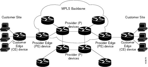

How MPLS Layer 3 VPNs work

The following figure depicts a basic MPLS VPN topology.

Summary

The key components involved in the process are:

  • Provider (P) router: Operates within the core of the provider network, switches MPLS labels, and does not attach VPN labels to packets.

  • Provider edge (PE) router: Connects directly to the customer edge (CE) router, attaches VPN labels to incoming packets, and manages MPLS core labels for packets traveling within the provider network.

  • Customer edge (CE) router: Sits at the edge of the customer's network, connects to the PE router, and interfaces with the provider’s network.

  • Customer (C) router: Functions within the customer’s internal network, routing data to and from the CE router.

MPLS Layer 3 VPNs use specialized routers and label-based packet forwarding to securely connect customer sites over a provider’s MPLS-enabled backbone. Each type of router has a specific role that ensures data is directed to the correct private network.

Workflow

These stages describe how MPLS Layer 3 VPNs work.

  1. The customer (C) router sends data toward an external network, forwarding packets to the customer edge (CE) router.
  2. The CE router passes outgoing packets to the provider edge (PE) router.
  3. The PE router attaches the appropriate VPN labels (based on the incoming interface or sub-interface) and MPLS core labels, and sends the packets into the provider (P) network.
  4. Provider (P) routers within the core forward packets based on MPLS labels, without modifying VPN labels.
  5. When the packets reach the PE router at the destination site, the router removes the MPLS core labels and forwards the packets to the appropriate CE router (and onward to the correct customer network), completing the VPN connection.

Result

This topology securely connects multiple customer sites by routing traffic across the provider’s MPLS backbone, using label forwarding to ensure each customer’s data remains private and correctly delivered to each site.


Benefits of MPLS L3VPN

MPLS L3VPN services offer several advantages for service providers and customers:

  • Scalable VPN deployment: Service providers can build scalable VPNs using both connection-oriented and point-to-point overlays, delivering value-added services without prior host coordination.

  • Centralized service delivery: Layer 3 VPNs enable targeted services for specific user groups, simplifying management through centralized control.

  • Security: Security is enforced at the provider network edge and across the backbone, ensuring customer packets are placed on the correct VPN.

  • Integrated Quality of Service (QoS): MPLS L3VPN supports multiple service levels, performance guarantees, and policy implementation directly within the VPN.

  • Simplified migration: Providers can deploy VPN services using a straightforward migration path, and customers are not required to support MPLS on their edge routers or modify their existing intranets.

These benefits help service providers deliver flexible, secure, and efficient VPN solutions tailored to a wide range of customer requirements.


Major components of MPLS L3VPN

An MPLS L3VPN component is a routing or forwarding element that

  • defines VPN membership with route target communities

  • propagates VRF reachability through MP-BGP peering, and

  • transports VPN traffic across the provider network with MPLS forwarding.

Component details

An MPLS-based VPN network has three major components:

  • VPN route target communities—A VPN route target community is a list of all members of a VPN community. VPN route targets need to be configured for each VPN community member.

  • Multiprotocol BGP (MP-BGP) peering of the VPN community PE routers—MP-BGP propagates VRF reachability information to all members of a VPN community. MP-BGP peering needs to be configured in all PE routers within a VPN community.

  • MPLS forwarding—MPLS transports all traffic between all VPN community members across a VPN service-provider network.

A one-to-one relationship does not necessarily exist between customer sites and VPNs. A given site can be a member of multiple VPNs. However, a site can associate with only one VRF. A customer-site VRF contains all the routes available to the site from the VPNs of which it is a member.


Virtual routing and forwarding tables

A virtual routing and forwarding table is a VPN-specific routing and forwarding context that

  • defines VPN membership for a customer site attached to a PE router

  • maintains separate routing and FIB tables for each VRF, and

  • controls which interfaces and routing protocol parameters belong to the VRF.

Feature history

The feature history table lists release support for this feature.

Table 2. Feature History Table

Feature Name

Release

Description

Virtual Routing and Forwarding Tables

Release 25.4.1

Introduced in this release on: Fixed Systems (8010 [ASIC: A100])(select variants only*)

*This feature is supported on:

  • 8011-32Y8L2H2FH

  • 8011-12G12X4Y-A/D

Virtual Routing and Forwarding Tables

Release 25.1.1

Introduced in this release on: Fixed Systems (8010 [ASIC: A100])(select variants only*)

*This feature is supported on Cisco 8011-4G24Y4H-I routers.

Virtual Routing and Forwarding Tables

Release 24.4.1

Introduced in this release on: Fixed Systems (8200 [ASIC: P100], 8700 [ASIC: P100, K100])(select variants only*); Modular Systems (8800 [LC ASIC: Q100, P100])(select variants only*)

The router now supports 2000 VRF instances which enhances network segmentation capabilities, allowing for more granular and efficient management of virtual routing and forwarding instances. This improvement supports larger and more complex network architectures, enabling service providers to offer more tailored services to their customers. The expanded VRF capacity ensures that businesses can grow their networks without compromising on performance or reliability. By accommodating up to 2000 VRFs, users benefit from greater flexibility and scalability, catering to diverse and demanding network environments.

*Previously this feature was supported on Q200 and Q100. It is now extended to:

  • 8712-MOD-M

  • 8212-48FH-M

  • 8711-32FH-M

  • 88-LC1-52Y8H-EM

  • 88-LC1-12TH24FH-E

  • 88-LC1-36EH

VRF details

Each VPN is associated with one or more VPN routing and forwarding (VRF) instances. A VRF defines the VPN membership of a customer site attached to a PE router. A VRF consists of the following components:

  • An IP version 4 (IPv4) unicast routing table

  • A derived FIB table

  • A set of interfaces that use the forwarding table

  • A set of rules and routing protocol parameters that control the information that is included in the routing table

These components are collectively called a VRF instance.

A one-to-one relationship does not necessarily exist between customer sites and VPNs. A site can be a member of multiple VPNs. However, a site can associate with only one VRF. A VRF contains all the routes available to the site from the VPNs of which it is a member.

Packet forwarding information is stored in the IP routing table and the FIB table for each VRF. A separate set of routing and FIB tables is maintained for each VRF. These tables prevent information from being forwarded outside a VPN and also prevent packets that are outside a VPN from being forwarded to a router within the VPN.


How VPN routing information works

The distribution of VPN routing information is controlled through the use of VPN route target communities, implemented by BGP extended communities. VPN routing information is distributed as follows:

Summary

The key components involved in the process are:

  • VPN route target communities: Specify which VPN routes can be exported from and imported into a VRF.

  • BGP extended communities: Carry the route target information in BGP updates, enabling precise route sharing.

  • VRF: Maintains its own routing table, controlling route import/export through configured route targets.

VPN routing information is distributed by controlling export and import through VPN route target communities, which are implemented by BGP extended communities. This allows selective sharing of routes among different VRFs to maintain network segmentation.

Workflow

These stages describe how VPN routing information works.

  1. When a VPN route is learned from a CE router and injected into BGP, it is associated with a list of VPN route target extended community attributes. This list is typically set from the export list of route targets configured for the VRF from which the route was learned.
  2. Each VRF has an import list of route target extended communities. For a VPN route to be imported into a VRF, it must carry at least one of the route target extended communities specified in that VRF’s import list. For example, if the import list includes route target communities A, B, and C, any VPN route carrying A, B, or C will be imported into the VRF.

Result

VPN routes are imported into a VRF only when their route target extended communities match the import list for that VRF, enabling controlled sharing of routing information between VPN segments.


How BGP distributes VPN routing information

A PE router learns IP prefixes from various sources, including static configuration on a CE router, eBGP sessions with a CE router, and interior gateway protocols like OSPF. The IP prefix is then converted into the VPN-IPv4 prefix using a 64-bit route distinguisher configured for the VRF. This process ensures a unique identifier for each customer site, even if private, unregistered IP addresses are used.

Summary

The key components involved in the process are:

  • PE router: Learns customer IP prefixes, converts them to VPN-IPv4 prefixes, and manages VRFs.

  • CE router: Supplies IP prefixes through static configuration or routing protocols.

  • BGP protocol with extensions: Distributes VPN-IPv4 reachability information among PE routers, ensuring only VPN members receive pertinent routes.

BGP enables routing between customer sites in a VPN by using Multiprotocol BGP extensions to propagate VPN-IPv4 reachability among participating routers.

Workflow

These stages how BGP distributes VPN routing information:

  1. Prefix learning: The PE router learns IP prefixes from the CE router via static configuration, an eBGP session, or an IGP such as OSPF.
  2. Prefix conversion: The PE router combines each IP prefix with a 64-bit route distinguisher to generate a VPN-IPv4 prefix, uniquely identifying the customer address.
  3. Route distribution: BGP, using Multiprotocol Extensions (RFC 2283), distributes reachability information for VPN-IPv4 prefixes among PE routers. Routes for a given VPN are learned only by other members of the same VPN.
  4. BGP communication: Reachability is propagated at two levels:
    • Internal BGP (iBGP): Distributed within the provider's autonomous system.
    • External BGP (eBGP): Shared between autonomous systems as needed.
  5. VPN member communication: Only routers that are members of the relevant VPN learn these VPN-IPv4 routes, enabling inter-site connectivity within the VPN.

Result

BGP distributes VPN-IPv4 reachability only to participating VPN members, enabling secure and scalable inter-site routing for customers while preventing route leaks and overlap between VPNs.


How MPLS forwarding works

Based on routing information stored in the VRF IP routing table and the VRF FIB table, packets are forwarded to their destination using MPLS.

Summary

The key components involved in the process are:

  • PE router: Connects to customer routers (CE routers), learns customer prefixes, assigns labels, and forwards traffic through the provider backbone.

  • CE router: Connects to a PE router and exchanges routing information for customer sites.

  • MPLS labels (top and VPN label): The top label determines the packet’s path across the provider network to the destination PE router; the VPN label identifies the final customer destination behind the PE router.

MPLS forwarding enables efficient transport of customer data across a service provider’s backbone by assigning and stacking labels on packets. This process directs traffic through the backbone and ensures delivery to the correct destination.

Workflow

These stages describe how MPLS forwarding works:

  1. The PE router learns customer prefixes from the connected CE router and assigns (binds) an MPLS label to each prefix.
  2. The PE router advertises the customer prefix along with its label to other PE routers in the network.
  3. When forwarding a packet from a CE router to a remote site, the ingress PE router stacks two labels on the packet: the top label (for backbone transport) and the VPN label (for ultimate destination).
  4. As the packet traverses the provider backbone, provider routers (P routers) forward the packet based on the top label.
  5. The destination PE router receives the packet, removes the top label, and examines the VPN label to determine which CE router should receive the packet.

Result

This process ensures that customer data is routed efficiently and securely across the service provider backbone to its intended destination using dynamic MPLS label switching.


How automatic route distinguisher assignment works

To enable efficient iBGP load balancing, each network VRF must have a unique route distinguisher. This prevents conflicts between identical prefixes received from multiple VPNs.

Summary

The key components involved in the process are:

  • VRF: Requires a unique route distinguisher to distinguish between identical prefixes from different VPNs.

  • BGP router ID: Provides the IP address used to construct the route distinguisher.

  • rd auto command: Assigns a persistent Type 1 route distinguisher to each VRF based on the router ID and an unused index.

Automatic route distinguisher assignment simplifies network configuration by ensuring that every network VRF receives a unique identifier for BGP load balancing.

Workflow

These stages describe how automatic route distinguisher assignment works:

  1. Configuration and management: In large-scale networks with thousands of routers and multiple VRFs, manual management of route distinguishers is complex. Cisco IOS XR simplifies this by using the rd auto command.
  2. Assignment using rd auto: Each router must have a unique BGP router ID. The rd auto command assigns a Type 1 route distinguisher to each VRF in the format ip-address:number, where the IP address is the router ID and the number is an unused index in the range 0 to 65535.
  3. Persistence and checkpointing: Assigned route distinguisher values are checkpointed so that they remain persistent across failover or process restart. If a route distinguisher is explicitly configured for a VRF, it is not overridden by the automatic assignment.

Result

Automatic route distinguisher assignment remains persistent across failover or process restart unless a route distinguisher is explicitly configured for a VRF.


MPLS L3VPN prerequisites

To configure MPLS Layer 3 VPN, ensure the following requirements are met:

  • You must belong to a user group associated with a task group that includes the necessary task IDs for these commands:

    • BGP

    • IGP

    • MPLS

    • MPLS Layer 3 VPN

  • If user group assignment prevents you from using a command, contact your AAA administrator for assistance.

  • The routers must support MPLS forwarding and Forwarding Information Base (FIB).


MPLS L3VPN restrictions

When designing or configuring MPLS L3VPN deployments, adhere to the following requirements and restrictions:

  • Do not configure MPLS packet fragmentation for packets that exceed the egress MTU. Fragmentation is unsupported for both IP-to-MPLS imposition and standard MPLS operations.

  • Set the MTU to the maximum value (9216) on all interfaces within the MPLS core to avoid fragmentation issues.

  • Accept that L3VPN prefix lookup yields a single path. When multiple paths are available at the IGP or BGP level, recognize that path selection occurs using a flow hash computed in the data plane.

  • Do not rely on per VRF aggregate statistics, as they are not supported.

  • For MPLS VPN Inter-AS deployments with ASBRs exchanging IPv4 routes and MPLS labels:

    • Configure a label switched path (LSP) between non-adjacent routers when using eBGP multihop.

    • Do not use Layer 3 VPN over SR-TE; this is not supported.

  • For label assignments in MPLS VPNs

    • Allocate a local label for every VRF.

    • Assign one VPN label per VRF.

    • Use per VRF label mode across the entire VRF deployment.

  • Do not exceed these maximum numbers of L3 interfaces per component when operating in P100 mode:

Component

Maximum number of L3 Interfaces Per Component

NPU (P100)

8000

Line card (88-LC1-36EH)

16000

Router

30000