L3VPN Configuration Guide for Cisco 8000 Series Routers, Cisco IOS XR Releases

PDF

L3VPN Configuration Guide for Cisco 8000 Series Routers, Cisco IOS XR Releases

MPLS L3VPN services using Segment Routing

Want to summarize with AI?

Log in

Introduces MPLS L3VPN with Segment Routing, detailing topology operations, guided MPLS core configuration using Segment Routing, and verification procedures to ensure correct L3VPN deployment over Segment Routing.


An MPLS L3VPN service with Segment Routing is a transport approach that

  • uses Segment Routing instead of MPLS LDP for MPLS L3VPN transport

  • applies Segment Routing directly to the MPLS architecture without changing the forwarding plane, and

  • uses IGP or BGP for label distribution.

Additional reference information

Currently, MPLS Label Distribution Protocol (LDP) is the widely used transport for MPLS L3VPN services. You can achieve better resilience and convergence for network traffic by transporting MPLS L3VPN services using Segment Routing (SR) instead of MPLS LDP. Segment Routing can be directly applied to the MPLS architecture without changing the forwarding plane. In a segment-routing network using the MPLS data plane, LDP or other signaling protocols are not required; instead, label distribution is performed by IGP (IS-IS or OSPF) or BGP. Removing protocols from the network simplifies its operation and makes it more robust and stable by eliminating the need for protocol interaction. Segment Routing also utilizes network bandwidth more effectively than traditional MPLS networks and offers lower latency.
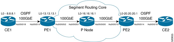

How MPLS L3VPN over Segment Routing works

Here is a network scenario in which an MPLS L3VPN service is transported using Segment Routing.

Summary

The key components involved in the process are:

  • CE routers: Devices (e.g., CE1 and CE2) at the customer premises connecting to the provider's network.

  • PE routers: ISP routers (example, PE1 and PE2) interfacing between customer and core networks, hosting customer VPNs.

  • P routers: ISP core routers forwarding labeled packets between PE routers.

  • OSPF protocol: Used as an Interior Gateway Protocol (IGP) to facilitate routing between CE and PE routers.

  • Autonomous Systems (AS): Distinct routing domains for customer (AS 65534) and ISP (AS 65000).

  • Virtual Routing and Forwarding (VRF): Logical instances (example, vrf1601) on PE routers to isolate customer traffic.

  • Route-targets: BGP attributes controlling VPN route import/export between VRFs.

  • Loopback interfaces: Simulated network addresses used for testing and routing stability.

Workflow

Figure 1. MPLS L3VPN over Segment Routing

These stages describe how MPLS L3VPN over Segment Routing works:

  1. Topology setup: CE1 and CE2 are deployed as customer routers connecting to the ISP network that contains two PE routers (PE1, PE2) and a P router.
  2. IGP configuration: OSPF is configured as the IGP between CE and PE routers, supporting label distribution through IS-IS, OSPF, or BGP (OSPF is used here).
  3. VPN separation: The customer's autonomous system (65534) peers with the ISP's autonomous system (65000) using VRF peering, preventing route advertisement into the global IPv4 table. PE routers host customer VRF instances and import/export route targets as needed.
  4. Loopback implementation: Loopback interfaces are designated to simulate network endpoints and ensure reliable routing.

Result

The topology is ready for configuration when the CE, PE, P, OSPF, autonomous system, VRF, route-target, and loopback roles are planned, enabling secure, isolated transport of customer VPN services using Segment Routing.


Configure Segment Routing on PE1, P, and PE2 routers

Configure Segment Routing on core routers (PE1, P, and PE2) in the MPLS network to enable traffic engineering and segment routing.

Perform these steps on each designated core router (PE1, P, and PE2) to activate Segment Routing using OSPF or IS-IS routing protocols. Ensure you use the correct values (router ID, prefix SID index, global block, and interface configurations) for each device.

Before you begin

Plan the OSPF or IS-IS core, Segment Routing global block, prefix SID indexes, and core interfaces for PE1, P, and PE2.

Follow these steps to enable Segment Routing in the MPLS core on PE1, P, and PE2 routers:

Procedure

1.

Configure OSPF for Segment Routing on each router.

Example:

Router-PE1# configure
Router-PE1(config)# router ospf dc-sr
Router-PE1(config-ospf)# router-id 192.0.2.10
Router-PE1(config-ospf)# segment routing mpls
Router-PE1(config-ospf)# segment routing forwarding mpls
Router-PE1(config-ospf)# mpls ldp sync
Router-PE1(config-ospf)# mpls ldp auto-config
Router-PE1(config-ospf)# segment-routing sr-prefer
Router-PE1(config-ospf)# segment-routing prefix-sid-map advertise-local
Router-PE1(config-ospf)# exit
Router-PE1(config-ospf)# area 1
Router-PE1(config-ospf-ar)# interface HundredGigE0/0/0/2
Router-PE1(config-ospf-ar-if)# exit
Router-PE1(config-ospf-ar)# interface Loopback0
Router-PE1(config-ospf-ar-if)# prefix-sid index 1
Router-PE1(config-ospf-ar-if)# commit
2.

Configure the Segment Routing global block on each router.

Example:

Router# configure
Router(config)# segment-routing
Router(config-sr)# global-block 180000 200000
Router(config-sr)# commit
Router(config-sr)# exit


3.

Configure IS-IS for Segment Routing on each router (if using IS-IS).

Example:


Router# configure
Router(config)# router isis ring
Router(config-isis)# is-type level-2-only
Router(config-isis)# net 49.0001.1921.6800.1001.00
Router(config-isis)# nsr
Router(config-isis)# distribute link-state
Router(config-isis)# nsf cisco
Router(config-isis)# address-family ipv4 unicast
Router(config-isis-af)# metric-style wide
Router(config-isis-af)# mpls traffic-eng level-1
Router(config-isis-af)# mpls traffic-eng router-id loopback0
Router(config-isis-af)# segment-routing mpls sr-prefer
Router(config-isis-af)# exit
Router(config-isis)# interface loopback0
Router(config-isis-if)# address-family ipv4 unicast
Router(config-isis-af)# prefix-sid index 30101
Router(config-isis-af)# exit
4.

Review the running configuration.

Example:

PE1
router ospf dc-sr
 router-id 192.0.2.10
 segment-routing mpls
 segment-routing forwarding mpls
 mpls ldp sync
 mpls ldp auto-config
 segment-routing sr-prefer
 segment-routing prefix-sid-map receive
 segment-routing prefix-sid-map advertise-local
 !
 area 1
  interface HundredGigE0/0/0/2
  !
  interface Loopback0
   prefix-sid index 1
  !
 !
!

configure
 segment-routing
  global-block 180000 200000
 !
!

configure
 router isis ring
  net 49.0001.1921.6800.1001.00
  nsr
  distribute link-state
  nsf cisco
  address-family ipv4 unicast
   metric-style wide
   mpls traffic-eng level-1
   mpls traffic-eng router-id Loopback0
   segment-routing mpls sr-prefer
 !
 interface Loopback0
  address-family ipv4 unicast
   prefix-sid index 30101
  !
 !

Example:

P node
router ospf dc-sr
 router-id 192.0.2.11
 segment-routing mpls
 segment-routing forwarding mpls
 mpls ldp sync
 mpls ldp auto-config
 segment-routing sr-prefer
 segment-routing prefix-sid-map receive
 segment-routing prefix-sid-map advertise-local
 !
 area 1
  interface HundredGigE0/0/1/0
  !
  interface HundredGigE0/0/1/1
  !
  interface Loopback0
   prefix-sid index 1
  !
 !
!

configure
 segment-routing
  global-block 180000 200000
 !
!

configure
 router isis ring
  net 49.0001.1921.6800.1002.00
  nsr
  distribute link-state
  nsf cisco
  address-family ipv4 unicast
   metric-style wide
   mpls traffic-eng level-1
   mpls traffic-eng router-id Loopback0
   segment-routing mpls sr-prefer
 !
 interface Loopback0
  address-family ipv4 unicast
   prefix-sid index 30102
  !
 !

Example:

PE2
router ospf dc-sr
 router-id 192.0.2.17
 segment-routing mpls
 segment-routing forwarding mpls
 mpls ldp sync
 mpls ldp auto-config
 segment-routing sr-prefer
 segment-routing prefix-sid-map receive
 segment-routing prefix-sid-map advertise-local
 !
 area 0
  interface HundredGigE0/0/0/19
  !
  interface Loopback0
   prefix-sid index 1
  !
 !
!

configure
 segment-routing
  global-block 180000 200000
 !
!

configure
 router isis ring
  net 49.0001.1921.6800.1003.00
  nsr
  distribute link-state
  nsf cisco
  address-family ipv4 unicast
   metric-style wide
   mpls traffic-eng level-1
   mpls traffic-eng router-id Loopback0
   segment-routing mpls sr-prefer
 !
 interface Loopback0
  address-family ipv4 unicast
   prefix-sid index 30103
  !

Segment Routing is configured and active in the MPLS core when the running configuration shows Segment Routing enabled and appropriate values on PE1, P, and PE2 routers.


Verify MPLS L3VPN configuration over Segment Routing

Ensure MPLS L3VPN over Segment Routing is functioning by monitoring label counter increments on core and edge routers.

This verification task confirms that transport and VPN label counters are increasing, which indicates proper operation of MPLS L3VPN over Segment Routing. You must complete the initial configuration before proceeding.

Before you begin

Complete MPLS L3VPN over Segment Routing configuration before you verify label counters.

Follow these steps to verify MPLS L3VPN label counters over Segment Routing:

Procedure

1.

On the core router (P node), verify the statistics for the IGP transport label, and confirm that label 64003 (in this example) is increasing.

Example:

Router-P# show mpls forwarding
Local  Outgoing    Prefix             Outgoing     Next Hop        Bytes
Label  Label       or ID              Interface                    Switched
------ ----------- ------------------ ------------ --------------- ---------
64003  Pop         SR Pfx (idx 0)     Hu0/0/0/0   192.0.2.32      572842

Verify the statistics in core router and ensure that the counter for IGP transport label (64003 in this example) is increasing.

P node:

2.

On PE1, verify the statistics for MPLS labels. Confirm that label counters such as 64001 and 60003 are increasing.

Example:

Router-PE1# show mpls forwarding
Local  Outgoing    Prefix             Outgoing     Next Hop        Bytes
Label  Label       or ID              Interface                    Switched
------ ----------- ------------------ ------------ ------------    --------
64001  60003       SR Pfx (idx 0)     Hu0/0/0/2    192.0.2.12      532978
3.

On PE2, verify the statistics for the VPN label, and confirm that label 24031 (in this example) is increasing.

Example:

Router-PE2# show mpls forwarding
Local  Outgoing    Prefix             Outgoing     Next Hop        Bytes
Label  Label       or ID              Interface                    Switched
------ ----------- ------------------ ------------ --------------- ---------
24031  Aggregate   vrf1601: Per-VRF Aggr[V]   \
                                      vrf1601                      0

If the IGP transport label and VPN label counters increase as expected on core and edge routers, MPLS L3VPN over Segment Routing is verified and operating correctly.