L3VPN Configuration Guide for Cisco 8000 Series Routers, Cisco IOS XR Releases

PDF

L3VPN Configuration Guide for Cisco 8000 Series Routers, Cisco IOS XR Releases

Carrier Supporting Carrier for L3VPN

Want to summarize with AI?

Log in

Introduces the Carrier Supporting Carrier concept for L3VPN, explaining foundational principles and illustrating customer-carrier and MPLS service-provider packet flow through end-to-end process descriptions.


A carrier supporting carrier (CSC) model is a service provider architecture that:

  • lets a backbone carrier provide a segment of its backbone network to another provider

  • uses CSC-CE and CSC-PE routers at the carrier edge, and

  • supports both Internet service provider (ISP) and BGP/MPLS VPN service-provider scenarios.

Feature history

The feature history table lists release support for this feature.

Table 1. Feature History Table

Feature Name

Release Information

Feature Description

Carrier Supporting Carrier for L3VPN

Release 25.4.1

Introduced in this release on: Fixed Systems (8700 [ASIC: K100])(select variants only*)

Introduced in this release on: Fixed Systems (8010 [ASIC: A100], 8700 [ASIC: K100])(select variants only*)

*This feature is supported on:

  • 8711-48Z-M

  • 8011-32Y8L2H2FH

  • 8011-12G12X4Y-A/D

Carrier Supporting Carrier for L3VPN

Release 25.1.1

Introduced in this release on: Fixed Systems (8010 [ASIC: A100])(select variants only*)

*This feature is supported on Cisco 8011-4G24Y4H-I routers.

Carrier Supporting Carrier for L3VPN

Release 24.4.1

Introduced in this release on: Fixed Systems (8700) (select variants only*)

*The Carrier Supporting Carrier for L3VPN functionality is now extended to the Cisco 8712-MOD-M routers.

Carrier Supporting Carrier for L3VPN

Release 24.3.1

Introduced in this release on: Fixed Systems (8200, 8700); Modular Systems (8800 [LC ASIC: P100]) (select variants only*)

*The Carrier Supporting Carrier for L3VPN functionality is now extended:

  • 8212-48FH-M

  • 8711-32FH-M

  • 88-LC1-52Y8H-EM

  • 88-LC1-12TH24FH-E

Carrier Supporting Carrier for L3VPN

Release 24.2.11

Introduced in this release on: Modular Systems (8800 [LC ASIC: P100]) (select variants only*)

*The Carrier Supporting Carrier for L3VPN functionality is now extended to routers with the 88-LC1-36EH line cards.

Carrier Supporting Carrier for L3VPN

Release 7.3.15

This feature enables MPLS VPN-based backbone carriers to allow customer carriers to use a segment of the backbone network. The backbone carrier can accommodate many customer carriers and provide access to the backbone. Customer carriers no longer have to bear the burden of configuring, operating, and maintaining their own backbone.

CSC terminology

  • Backbone carrier: Service provider that provides a segment of the backbone network to another provider, offering BGP and MPLS VPN services.

  • Customer carrier: Service provider that uses the provided backbone segment. This may be an Internet service provider (ISP) or a BGP/MPLS VPN service provider.

  • CSC-CE router: A customer edge router that is part of a customer network and connects to a provider edge (CSC-PE) router. The CSC-CE sits on the edge of the customer carrier network.

  • CSC-PE router: A provider edge router that is part of the service provider's network connected to a CSC-CE router. The CSC-PE sits on the edge of the backbone carrier network.

  • Types of customer carriers:

    • Internet service provider (ISP)

    • BGP/MPLS VPN service provider


How packet flow works when the customer carrier is an ISP

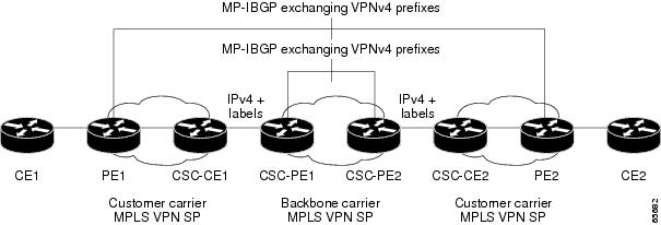
The following topology shows a network configuration where the customer carrier is an ISP. The customer carrier has two sites, each of which is a point of presence (POP). The customer carrier connects these sites using a VPN service provided by the backbone carrier. The backbone carrier uses MPLS to provide VPN services. The ISP sites use MPLS.

Summary

The key components involved in the process are:

  • Customer Edge (CE) routers: Connect the ISP's local sites (POPs) to the backbone carrier and exchange routes via eBGP.

  • Provider Edge (PE) routers: Interface between customer sites and backbone, distributing VPN routes and labels using multiprotocol iBGP.

  • Backbone carrier network: Uses MPLS to provide VPN services connecting ISP POPs.

  • MPLS protocol: Enables label-based forwarding across backbone and ISP sites.

  • eBGP and iBGP protocols: Distribute IPv4 routes, MPLS labels, and VPNv4 routes between CE and PE routers.

A customer carrier ISP topology involves two sites (each a POP), connected via a VPN service provided by a backbone carrier using MPLS. The ISP sites also use MPLS. Packet flow and route distribution leverage eBGP and iBGP protocols.

Workflow

Figure 1. Customer Carrier Is an ISP
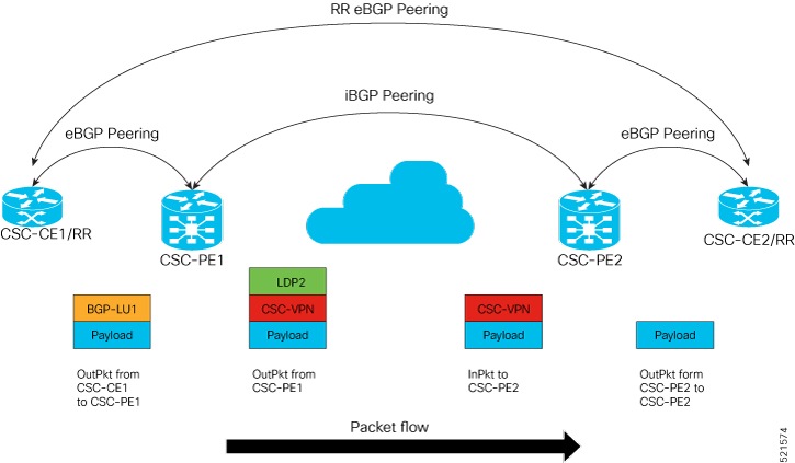
Figure 2. MPLS Single-Label Packet Flow into CSC-CE (CSC-CE/RR eBGP Peering)

These stages describe how packet flow works when the customer carrier is an ISP.

  1. Topology establishment: The ISP customer carrier sets up two points of presence (POPs), connecting these via a VPN service from the backbone carrier.
  2. MPLS VPN configuration: Both ISP sites and the backbone carrier enable MPLS for efficient VPN service delivery.
  3. Route and label distribution: CE and PE routers use eBGP to exchange IPv4 routes and MPLS labels. PE routers internally use multiprotocol iBGP to distribute VPNv4 routes across the backbone.
  4. Packet forwarding into CSC-CE: When traffic flows into the customer carrier's CE device (CSC-CE), it follows a single-label MPLS path based on the route information distributed by eBGP and iBGP.
  5. Traffic confirmation: The process concludes as the topology delivers traffic into CSC-CE, using the distributed labels and routes to achieve efficient packet transfer.

Result

The ISP customer-carrier scenario uses the described MPLS topology and routing protocols to forward packets efficiently into CSC-CE, ensuring reliable connectivity between ISP POPs via the backbone VPN.


How packet flow works when the customer carrier is an MPLS service provider

In an MPLS VPN environment, a customer carrier may have sites in multiple locations and uses MPLS to carry VPN traffic among those sites. The backbone service provider connects these sites and may use either MPLS or IP tunnels within its own core. Packet flow between the two carriers requires both routing coordination via eBGP and label distribution protocols like BGP-LU and LDP.

Summary

The key components involved in the process are:

  • Backbone carrier: Provides core network infrastructure for transporting MPLS or IP-tunneled traffic and interconnects with customer carriers at the service-provider edge.

  • Customer carrier: Operates its own MPLS network, connects multiple customer sites, and peers with the backbone carrier via BGP/MPLS VPN.

  • CSC-CE router: The customer carrier’s edge router that exchanges routing information with the backbone carrier and handles redistributed eBGP routes using IGP.

  • CSC-PE router: The backbone carrier’s edge router that peers with the customer carrier’s CSC-CE via eBGP.

MPLS service-provider packet flows enable two independent carriers (customer and backbone) to interconnect via BGP/MPLS VPN topology, efficiently routing packets between customer sites across different service-provider domains.

Workflow

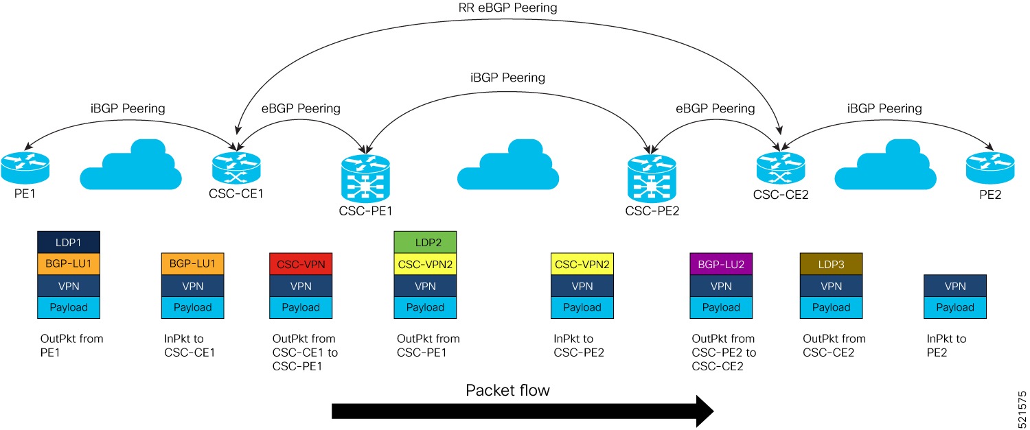
Figure 3. Customer Carrier is an MPLS VPN Service Provider
Figure 4. MPLS Two-Labels Packet Flow into CSC-CE (CSC-CE/RR BGP Peering)

These stages describe how packet flow works when the customer carrier is an MPLS service provider.

  1. Service-provider topology establishment: The backbone and customer carriers establish a BGP/MPLS VPN interconnection, with CSC-CE and CSC-PE routers at their respective network edges.
  2. Label distribution protocol setup: The customer carrier configures BGP-LU (label unicast) and LDP (Label Distribution Protocol) in its core to support MPLS label switching for VPN traffic.
  3. Route exchange and redistribution: The CSC-CE router receives eBGP-learned routes from the backbone carrier’s CSC-PE router and redistributes them into the customer carrier's IGP to ensure consistent routing within its domain.
  4. Packet forwarding with two-label stack: When packets reach the CSC-CE, they carry a two-label MPLS stack: the top label represents the backbone (transport) path, and the second label identifies the end VPN destination in the customer carrier network.
  5. Final delivery to customer site: The CSC-CE removes the appropriate labels and forwards the packet to the target customer site over the MPLS-enabled customer carrier network.

Result

The MPLS service-provider customer-carrier solution allows secure, scalable, and efficient end-to-end traffic forwarding between customer sites across multiple provider domains using label-based routing and VPN technologies.