L3VPN Configuration Guide for Cisco 8000 Series Routers, Cisco IOS XR Releases

PDF

L3VPN Configuration Guide for Cisco 8000 Series Routers, Cisco IOS XR Releases

IPv6 VPN provider edge transport services

Want to summarize with AI?

Log in

Introduces IPv6 VPN provider edge transport services using MPLS, detailing 6PE and 6VPE architectures, service integration options, inter-AS requirements, solution benefits, operational workflows, edge and customer device roles, OSPFv3 route exchange, and configuration procedures for BGP and OSPFv3 connectivity.


IPv6 VPN provider edge transport services are network transport methods that

  • use the existing MPLS IPv4 core infrastructure to support IPv6 communication

  • enable IPv6 sites to communicate across MPLS label switched paths (LSPs), and

  • leverage multiprotocol BGP extensions to exchange IPv6 reachability information and MPLS labels.

Implementation context

IPv6 Provider Edge (6PE) and IPv6 VPN Provider Edge (6VPE) use the existing MPLS IPv4 core infrastructure to transport IPv6 traffic. These services enable IPv6 sites to communicate with each other over an MPLS IPv4 core network by establishing MPLS label switched paths (LSPs).

The feature uses multiprotocol Border Gateway Protocol (BGP) extensions configured on the provider edge (PE) routers within the IPv4 network. These extensions allow the exchange of IPv6 reachability information and assign an MPLS label for each IPv6 address prefix.

Edge routers are configured as dual-stack, running both IPv4 and IPv6 protocols. They use IPv4-mapped IPv6 addresses to facilitate the exchange of IPv6 prefix reachability.

To implement 6PE or 6VPE, familiarity with MPLS and BGP4 configuration and troubleshooting is essential.

6PE and 6VPE services

6PE and 6VPE services are provider edge deployment techniques that

  • integrate IPv6 services over existing service provider backbones

  • preserve MPLS IPv4 infrastructure while adding IPv6 service reachability, and

  • use dual-stack edge routers and multiprotocol BGP extensions to exchange reachability information.

Feature history

The feature history table lists release support for this feature.

Table 1. Feature History Table

Feature Name

Release

Description

6PE/6VPE

Release 25.4.1

Introduced in this release on: Fixed Systems (8010 [ASIC: A100], 8700 [ASIC: K100])(select variants only*)

*This feature is supported on:

  • 8711-48Z-M

  • 8011-32Y8L2H2FH

  • 8011-12G12X4Y-A/D

6PE/6VPE

Release 25.1.1

Introduced in this release on: Fixed Systems (8010 [ASIC: A100])(select variants only*)

*This feature support is now supported on Cisco 8011-4G24Y4H-I routers.

6PE/6VPE

Release 24.4.1

Introduced in this release on: Fixed Systems (8200 [ASIC: P100], 8700 [ASIC: K100])(select variants only*); Modular Systems (8800 [LC ASIC: Q100, P100])(select variants only*)

The router now enables seamless integration of IPv6 networks over an MPLS backbone, allowing service providers to offer IPv6 services without changing the core MPLS infrastructure. This feature facilitates IPv6 routing by leveraging existing IPv4 MPLS paths, ensuring efficient and scalable network expansion. IPv6 prefixes are advertised as VPNv4 routes, which simplifies deployment and reduces operational complexity. This approach requires no IPv6 capabilities in the MPLS core, leading to cost savings and a smoother transition to IPv6.

*Previously this feature was supported on Q200 and Q100. It is now extended to:

  • 8712-MOD-M

  • 8212-48FH-M

  • 8711-32FH-M

  • 88-LC1-52Y8H-EM

  • 88-LC1-12TH24FH-E

  • 88-LC1-36EH


IPv6 service integration options

Multiple techniques are available to integrate IPv6 services over service provider core backbones:

  • Dedicated IPv6 network: Runs over various underlying data link layers.

  • Dual-stack IPv4-IPv6 backbone: Operates both IPv4 and IPv6 protocols in parallel.

  • MPLS backbone leverage: Uses an existing MPLS backbone to carry IPv6 traffic.

These solutions are deployed on service provider backbones when the volume of IPv6 traffic and revenue justifies the investment and associated risks. Favorable conditions allow for the introduction of native IPv6 services from the network edge in a scalable way, avoiding IPv6 addressing constraints and preserving a stable IPv4 backbone. Maintaining backbone stability is critical, especially for service providers that have recently stabilized their IPv4 infrastructure.

Service providers operating an MPLS/IPv4 infrastructure often use similar approaches, as multiple scenarios for offering IPv6 services over MPLS are possible. Cisco Systems, for example, developed the Cisco 6PE (IPv6 Provider Edge Router over MPLS) solution to meet these requirements.


6PE and 6VPE Inter-AS and next-hop behavior

Ensure that your deployment follows these requirements for 6PE and 6VPE Inter-AS operations:

  • Support Border Gateway Protocol (BGP) to enable relevant address families and allocate and distribute PE and ASBR labels for Inter-AS 6PE deployments.

  • Cisco IOS XR must display actual IPv4 next-hop addresses for IPv6 labeled-unicast and VPNv6 prefixes. IPv4-mapped-to-IPv6 format is not supported.


Benefits of 6PE and 6VPE

Service providers who currently deploy MPLS experience these benefits of Cisco 6PE/6VPE:

  • Minimal operational cost and risk—No impact on existing IPv4 and MPLS services.

  • Provider edge routers upgrade only—A 6PE/6VPE router can be an existing PE router or a new one dedicated to IPv6 traffic.

  • No impact on IPv6 customer edge routers—The ISP can connect to any customer CE running Static, IGP or EGP.

  • Production services ready—An ISP can delegate IPv6 prefixes.

  • IPv6 introduction into an existing MPLS service—6PE/6VPE routers can be added at any time


How IPv6 over MPLS backbones works

The 6PE mechanism allows operators to introduce IPv6 services without disrupting or upgrading their existing MPLS IPv4 backbone. Label-based forwarding ensures efficient packet transit and preserves network stability.

Summary

The key components involved in the process are:

  • IPv6 domain: A network area using IPv6 addresses and protocols requiring connectivity across the backbone.

  • MPLS IPv4 core network: The underlying infrastructure that forwards packets based on MPLS labels, not IP headers.

  • 6PE Provider Edge Router: A specialized edge router that encapsulates IPv6 packets within MPLS labels for transit across the IPv4 backbone.

IPv6 over MPLS backbones enables seamless communication between IPv6 domains by leveraging an existing MPLS IPv4 core network. This implementation avoids reconfiguring core routers and requires no infrastructure upgrades, providing a cost-effective solution for IPv6 deployment.

Workflow

These stages describe how IPv6 over MPLS backbones works:

  1. IPv6 packet origination: An IPv6 domain generates an IPv6 packet destined for another IPv6 domain across the backbone.
  2. Provider Edge router encapsulation: The 6PE-enabled provider edge router encapsulates the IPv6 packet within an MPLS label, preparing it for transit.
  3. Transit across MPLS IPv4 core: The MPLS IPv4 core network transports the labeled packet solely based on the MPLS label, bypassing the need to interpret IPv6 headers.
  4. Provider Edge router decapsulation: At the destination edge, another 6PE router removes the MPLS label and routes the packet into the target IPv6 domain.
  5. Reachability exchange: Provider edge routers share reachability information using BGP extensions to ensure end-to-end IPv6 connectivity.

Result

IPv6 domains successfully communicate across the MPLS IPv4 backbone by utilizing MPLS label-switched paths (LSPs) and reachability exchange. The solution leverages the existing MPLS infrastructure, offering a scalable and low-impact IPv6 deployment.


IPv6 on provider edge and customer edge routers

A provider edge and customer edge router are network devices that

  • interconnect IPv6 islands over an MPLS IPv4 core as part of 6PE and 6VPE deployments

  • exchange routes between each other to enable seamless IPv6 communication, and

  • support multipath behavior to provide load sharing and redundancy.


Roles of service provider edge routers in MPLS IPv6 deployments

Service provider edge routers play a crucial part in enabling IPv6 services over an MPLS network using technologies such as 6PE (IPv6 Provider Edge) and 6VPE (IPv6 VPN Provider Edge). These routers offer several key roles and advantages:

  • Protocol support: Enable delivery of IPv6 services (both global routing and VPN), leveraging existing MPLS infrastructure.

  • Infrastructure efficiency: Do not require hardware, software, or configuration upgrades in the core network; minimize impact on ongoing revenue-generating IPv4 traffic.

  • Service versatility: Support multiservice capabilities including Layer 3 VPNs, QoS, traffic engineering, fast re-routing, and seamless integration of ATM and IP switching.

These features allow service providers to deploy IPv6 and VPN services efficiently without disrupting current operations or requiring large-scale upgrades. Edge routers thus act as the main interface for MPLS-based IPv6 service delivery to customers.


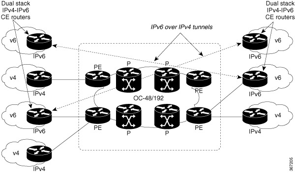
How customer edge router tunnels carry IPv6

Tunnel meshing is required as the number of CEs to connect increases. Additionally, delegating a global IPv6 prefix for an ISP can be challenging in this topology.

Summary

The key components involved in the process are:

  • Customer Edge (CE) router: Acts as the tunnel endpoint and encapsulates IPv6 packets for transport over an MPLS IPv4 network.

  • Provider Edge (PE) router: Maintains standard MPLS connectivity and does not require configuration changes for IPv6 tunneling.

  • Provider (P) router: Remains unchanged and forwards packets using the existing MPLS IPv4 infrastructure.

Using tunnels on customer edge (CE) routers is the simplest way to deploy IPv6 over MPLS networks. This approach does not affect MPLS operation or infrastructure and requires no changes to provider (P) routers or provider edge (PE) routers.

Workflow

Figure 1. IPv6 Using Tunnels on the CE Routers

These stages describe how customer edge router tunnels carry IPv6:

  1. The CE router encapsulates IPv6 packets inside IPv4 tunnels.
  2. Encapsulated packets traverse the service provider's MPLS IPv4 core network without requiring changes to P or PE routers.
  3. On reaching the destination CE router, IPv6 packets are decapsulated and forwarded to the customer network.

Result

Customer edge tunnel endpoints successfully carry IPv6 traffic while provider edge routers maintain standard IPv4 MPLS connectivity, enabling IPv6 deployment without major core network changes.


How IPv6 provider edge multipath works

Internal and external BGP multipath for IPv6 allows the IPv6 router to balance load between several paths (for example, the same neighboring autonomous system (AS) or sub-AS, or the same metrics) to reach its destination. The 6PE multipath feature uses multiprotocol internal BGP (MP-IBGP) to distribute IPv6 routes over the MPLS IPv4 core network and to attach an MPLS label to each route.

Summary

The key components involved in the process are:

  • IPv6 router: Selects multiple available BGP paths to forward IPv6 traffic.

  • Internal and external BGP multipath: Supports load sharing by distributing traffic across several paths, potentially within the same neighboring autonomous system (AS) or sub-AS.

  • Multiprotocol internal BGP (MP-IBGP): Distributes IPv6 routes as MPLS-labeled packets across the IPv4 core network.

IPv6 provider edge multipath enables load balancing and redundancy in service provider networks by allowing routers to use multiple internal or external BGP paths for IPv6 traffic.

Workflow

These stages describe how IPv6 provider edge multipath works:

  1. Path selection: The IPv6 provider edge (6PE) router evaluates available BGP paths to the destination, considering internal and external multipath scenarios.
  2. Label distribution: MP-IBGP distributes IPv6 routes and attaches an MPLS label to each route across the IPv4 MPLS core.
  3. Forwarding table installation: When multipath is enabled, all MPLS-labeled paths are installed in the forwarding table, enabling load balancing.
  4. Traffic distribution: IPv6 traffic is distributed across multiple paths based on the available MPLS label information.

Result

IPv6 traffic is efficiently load-shared and benefits from redundant paths, improving network resiliency and overall performance.


OSPFv3 CE-to-PE route exchange services

OSPFv3 CE-to-PE route exchange services are routing capabilities that

  • support multiple VRFs per OSPFv3 routing process

  • use OSPFv3 PE-CE extensions in the VPN environment, and

  • support VRF lite deployment without a BGP or MPLS based backbone.

Additional reference information

The Open Shortest Path First version 3 (OSPFv3) IPv6 VPN Provider Edge (6VPE) feature adds VPN routing and forwarding (VRF) and provider edge-to-customer edge (PE-CE) routing support to Cisco IOS XR OSPFv3 implementations. This feature enables:

  • Multiple VRF support per OSPFv3 routing process.

  • OSPFV3 PE-CE extensions.


Multiple VRF support in OSPFv3

OSPFv3 supports multiple VRFs in a single routing process, which enables scaling to tens or hundreds of VRFs without overloading route processor resources. Multiple OSPFv3 processes can be configured on a single router, allowing for partitioned VRF processing across several route processors in large-scale VRF deployments. This capability can also be used to isolate the default routing table or high-impact VRFs from regular VRFs. It is recommended to use a single process for all VRFs. If needed, a second OSPFv3 process should be configured for IPv6 routing.

Note

A maximum of four OSPFv3 processes are supported.


OSPFv3 PE-CE extension requirements for IPv6 VPN environments

The following facts outline key requirements and features of OSPFv3 PE-CE extensions in the context of IPv6 VPN:

  • Service Providers increasingly deploy IPv6 protocol in modern customer networks.

  • VPN services must support both IPv4 and IPv6 protocols for customer environments.

  • To support IPv6, routing protocols require additional extensions to operate in VPN environments.

  • OSPFv3 must be extended specifically for operation at Provider Edge (PE) and Customer Edge (CE) links in IPv6 VPNs.


OSPFv3 VRF lite behavior

To comply with the requirements for OSPFv3 VRF lite deployment, ensure that you:

  • Disable DN bit processing in the VRF lite environment.

  • Prevent automatic ABR status assignment in VRF contexts (except default VRF), regardless of connectivity to area 0. In the VRF lite environment, automatic ABR status setting must be disabled.

You must run the capability vrf-lite command in the OSPFv3 VRF configuration submode to enable VRF lite.


Configure 6PE and 6VPE

Enable the transport of IPv6 prefixes across an IPv4 backbone by configuring 6PE and 6VPE protocols on PE routers.

Use 6PE and 6VPE to allow IPv6 reachability and VPN functionality across an IPv4 cloud. Supported routing protocols vary:

  • For 6PE: BGP, OSPF, IS-IS, and Static protocols are supported to learn routes from both clouds.

  • For 6VPE: Only BGP and Static protocols are supported for learning routes from IPv4 and IPv6 clouds. OSPFv3 is supported between PE and CE routers.

Before you begin

  • Plan which PE routers will participate in both the IPv4 and IPv6 clouds.

  • Configure route policies before attaching them to routers.

  • Set label allocation mode to "per-vrf" on all routers, including peer routers.

Follow these steps to configure 6PE and 6VPE:

Procedure

1.

Configure BGP settings and enable required address families.

Example:

Router#configure
Router(config)#router bgp 10
Router(config-bgp)#bgp router-id 192.0.2.10
Router(config-bgp)#graceful-restart
Router(config-bgp)#log neighbor changes detail
Router(config-bgp)#address-family ipv6 unicast
Router(config-bgp-af)#redistribute connected
Router(config-bgp-af)#redistribute ospfv3 7
Router(config-bgp-af)#allocate-label all
Router(config-bgp-af)#commit
Router(config-bgp)#neighbor 66:1:2::2
Router(config-bgp-nbr)#remote-as 102
Router(config-bgp-nbr)#address-family ipv6 unicast
Router(config-bgp-nbr-af)#route-policy pass-all in
Router(config-bgp-nbr-af)#route-policy pass-all out
Router(config-bgp-nbr-af)#commit
Router(config-bgp)#neighbor 192.0.2.11
Router(config-bgp-nbr)#remote-as 10
Router(config-bgp-nbr)#update-source Loopback0
Router(config-bgp-nbr)#address-family vpnv4 unicast
Router(config-bgp-nbr-af)#address-family ipv6 labeled-unicast
Router(config-bgp-nbr-af)#address-family vpnv6 unicast
Router(config-bgp-nbr-af)#commit
Router(config-bgp-nbr-af)#exit
Router(config-bgp-nbr)#exit
Router(config-bgp)#vrf red
Router(config-bgp-vrf)#rd 500:1
Router(config-bgp-vrf)#address-family ipv4 unicast
Router(config-bgp-vrf-af)#label mode per-vrf
Router(config-bgp-vrf-af)#redistribute connected
Router(config-bgp-vrf-af)#redistribute static
Router(config-bgp-vrf-af)#exit
Router(config-bgp-vrf)#address-family ipv6 unicast
Router(config-bgp-vrf-af)#label mode per-vrf
Router(config-bgp-vrf-af)#redistribute connected
Router(config-bgp-vrf-af)#redistribute static
Router(config-bgp-vrf-af)#commit
Router(config)#interface HundredGigE0/0/1/0
Router(config-if)#vrf red
Router(config-if)#ipv6 address 4002:110::1/128
Router(config-if)#exit
Router(config)#vrf red
Router(config-vrf)#address-family ipv4 unicast
Router(config-vrf-af)#label mode per-vrf
Router(config-vrf-af)#import route-target
Router(config-vrf-import-rt)#500:1
Router(config-vrf-import-rt)#!
Router(config-vrf-import-rt)#export route-target
Router(config-vrf-export-rt)#500:1
Router(config-vrf-export-rt)#!
Router(config-vrf-export-rt)#address-family ipv6 unicast
Router(config-vrf-af)#label mode per-vrf
Router(config-vrf-af)#import route-target
Router(config-vrf-import-rt)#500:1
Router(config-vrf-import-rt)#!
Router(config-vrf-import-rt)#export route-target
Router(config-vrf-export-rt)#500:1
Router(config-vrf-export-rt)#commit
2.

Configure BGP neighbors for IPv6 and VPN connectivity.

Example:

Router(config-bgp)#neighbor 66:1:2::2
Router(config-bgp-nbr)#remote-as 102
Router(config-bgp-nbr)#address-family ipv6 unicast
Router(config-bgp-nbr-af)#route-policy pass-all in
Router(config-bgp-nbr-af)#route-policy pass-all out
Router(config-bgp-nbr-af)#commit
Router(config-bgp)#neighbor 192.0.2.11
Router(config-bgp-nbr)#remote-as 10
Router(config-bgp-nbr)#update-source Loopback0
Router(config-bgp-nbr)#address-family vpnv4 unicast
Router(config-bgp-nbr-af)#address-family ipv6 labeled-unicast
Router(config-bgp-nbr-af)#address-family vpnv6 unicast
Router(config-bgp-nbr-af)#commit
Router(config-bgp-nbr-af)#exit
Router(config-bgp-nbr)#exit
3.

Configure VRF settings and label modes.

Example:

Router(config-bgp)#vrf red
Router(config-bgp-vrf)#rd 500:1
Router(config-bgp-vrf)#address-family ipv4 unicast
Router(config-bgp-vrf-af)#label mode per-vrf
Router(config-bgp-vrf-af)#redistribute connected
Router(config-bgp-vrf-af)#redistribute static
Router(config-bgp-vrf-af)#exit
Router(config-bgp-vrf)#address-family ipv6 unicast
Router(config-bgp-vrf-af)#label mode per-vrf
Router(config-bgp-vrf-af)#redistribute connected
Router(config-bgp-vrf-af)#redistribute static
Router(config-bgp-vrf-af)#commit
4.

Configure interface and VRF address settings.

Example:

Router(config)#interface HundredGigE0/0/1/0
Router(config-if)#vrf red
Router(config-if)#ipv6 address 4002:110::1/128
Router(config-if)#exit
Router(config)#vrf red
Router(config-vrf)#address-family ipv4 unicast
Router(config-vrf-af)#label mode per-vrf
Router(config-vrf-af)#import route-target
Router(config-vrf-import-rt)#500:1
Router(config-vrf-import-rt)#exit
Router(config-vrf-import-rt)#export route-target
Router(config-vrf-export-rt)#500:1
Router(config-vrf-export-rt)#exit
Router(config-vrf-export-rt)#address-family ipv6 unicast
Router(config-vrf-af)#label mode per-vrf
Router(config-vrf-af)#import route-target
Router(config-vrf-import-rt)#500:1
Router(config-vrf-import-rt)#exit
Router(config-vrf-import-rt)#export route-target
Router(config-vrf-export-rt)#500:1
Router(config-vrf-export-rt)#commit
5.

Set route-target import and export for VRF.

Example:

Router(config)#vrf red
Router(config-vrf)#address-family ipv4 unicast
Router(config-vrf-af)#label mode per-vrf
Router(config-vrf-af)#import route-target
Router(config-vrf-import-rt)#500:1
Router(config-vrf-import-rt)#exit
Router(config-vrf-import-rt)#export route-target
Router(config-vrf-export-rt)#500:1
Router(config-vrf-export-rt)#exit
Router(config-vrf-export-rt)#address-family ipv6 unicast
Router(config-vrf-af)#label mode per-vrf
Router(config-vrf-af)#import route-target
Router(config-vrf-import-rt)#500:1
Router(config-vrf-import-rt)#exit
Router(config-vrf-import-rt)#export route-target
Router(config-vrf-export-rt)#500:1
Router(config-vrf-export-rt)#commit

This example shows how to configure 6PE on PE routers to transport the IPv6 prefixes across the IPv4 cloud. Ensure that you configure 6PE on PE routers participating in both the IPv4 cloud and IPv6 clouds. Pointers:

  • For 6PE, all routing protocols supported on Cisco IOS XR (BGP, OSPF, IS-IS, Static) can be used for route learning.

  • For 6VPE, only BGP and Static protocols are supported for route learning, and OSPFv3 can be used between PE and CE routers.

  • It is mandatory to configure per-vrf label allocation mode on all routers (including peers).

  • Route policies must be created prior to configuring 6PE/6VPE.

  • Starting from Cisco IOS XR Release 7.5.3, BGP assigns a label value of 2 (IPv6 Explicit NULL Label) to IPv6 prefixes, replacing earlier random label assignment.

6.

Review the running configuration.

Example:

router bgp 10
bgp router-id 192.0.2.10
bgp graceful-restart
bgp log neighbor changes detail
!
address-family ipv6 unicast
 redistribute connected
  redistribute ospfv3 7
  allocate-label all
!
!
neighbor 66:1:2::2
  remote-as 201
  address-family ipv6 unicast
   route-policy pass-all in
   route-policy pass-all out
  !
!
neighbor 192.0.2.11
  remote-as 10
  update-source Loopback0
  address-family vpnv4 unicast
  !
  address-family ipv6 labeled-unicast
  !
  address-family vpnv6 unicast
!
vrf red
  rd 500:1
  address-family ipv4 unicast
   label mode per-vrf
   redistribute connected
   redistribute static
  !
  address-family ipv6 unicast
   label mode per-vrf
   redistribute connected
   redistribute static
  !
 !
!
interface HundredGigE0/0/1/0
vrf red
Ipv6 address 4002:110::1/128
!
exit
vrf red
address-family ipv4 unicast
import route-target
500:1
!
export route-target
500:1
!
!
address-family ipv6 unicast
import route-target
500:1
!
export route-target
500:1
!
7.

Verify the configuration.

Router# show route ipv6
Codes: C - connected, S - static, R - RIP, B - BGP, (>) - Diversion path
       D - EIGRP, EX - EIGRP external, O - OSPF, IA - OSPF inter area
       N1 - OSPF NSSA external type 1, N2 - OSPF NSSA external type 2
       E1 - OSPF external type 1, E2 - OSPF external type 2, E - EGP
       i - ISIS, L1 - IS-IS level-1, L2 - IS-IS level-2
       ia - IS-IS inter area, su - IS-IS summary null, * - candidate default
       U - per-user static route, o - ODR, L - local, G  - DAGR, l - LISP
       A - access/subscriber, a - Application route
       M - mobile route, r - RPL, (!) - FRR Backup path
Gateway of last resort is not set

L    ::ffff:127.0.0.0/104
      [0/0] via ::, 02:10:49
C    66:1:2::/64 is directly connected,
      02:09:39, TenGigE0/0/0/10.2
L    66:1:2::1/128 is directly connected,
      02:09:39, TenGigE0/0/0/10.2
C   66:1:3::/64isdirectlyconnected,
[20/0] via fe80::200:2cff:fe64:99e2, 02:07:38, TenGigE0/0/0/10.2
B    2000:0:0:1c::/64
      [20/0] via fe80::200:2cff:fe64:99e2, 02:07:38, TenGigE0/0/0/10.2
B    2000:0:0:1d::/64
Local PE :
Router# show bgp ipv6 labeled-unicast 2000:0:0:1c::/64
BGP routing table entry for 2000:0:0:1c::/64
Versions:
  Process           bRIB/RIB  SendTblVer
  Speaker               5033        5033
    Local Label: 66313
Paths: (1 available, best #1)
  Advertised to update-groups (with more than one peer):
    0.1
  Advertised to peers (in unique update groups):
    192.0.2.11
  Path #1: Received by speaker 0
  Advertised to update-groups (with more than one peer):
    0.1
  Advertised to peers (in unique update groups):
    192.0.2.11
  201
    66:1:2::2 from 66:1:2::2 (192.0.2.12)
      Origin IGP, localpref 100, valid, external, best, group-best
      Received Path ID 0, Local Path ID 0, version 5033
      Origin-AS validity: not-found

Remote PE
Router# show bgp ipv6 labeled-unicast 2000:0:0:1c::/64
BGP routing table entry for 2000:0:0:1c::/64
Versions:
  Process           bRIB/RIB  SendTblVer
  Speaker             139679      139679
Paths: (1 available, best #1)
  Advertised to update-groups (with more than one peer):
    0.2
  Path #1: Received by speaker 0
  Advertised to update-groups (with more than one peer):
    0.2
  201
    192.0.2.10 (metric 5) from 192.0.2.11 (192.0.2.10)
      Received Label 66313
      Origin IGP, localpref 100, valid, internal, best, group-best, labeled-unicast
      Received Path ID 0, Local Path ID 0, version 139679
      Originator: 192.0.2.10, Cluster list: 192.0.2.13

Configure OSPFv3 between PE and CE routers

Establish OSPFv3 routing sessions between provider edge (PE) and customer edge (CE) routers for IPv6 connectivity within a VRF.

Configure PE-to-CE routing sessions that use Open Shortest Path First version 3.Use OSPFv3 to enable dynamic routing between PE and CE devices over an MPLS VPN, leveraging VRF for traffic segmentation.

Before you begin

Plan the required OSPFv3 process ID, router ID, VRF name, OSPF area, and identify the relevant interfaces that will participate in routing.

Procedure

1.

Configure OSPFv3 between PE and CE routers.

Example:

Router# configure
Router(config)# router ospfv3 7
Router(config-ospfv3)# router-id 10.200.1.7
Router(config-ospfv3)# vrf vrf1
Router(config-ospfv3-vrf)# area 7
Router(config-ospfv3-vrf-ar)# interface Loopback7
Router(config-ospfv3-vrf-ar-if)# exit
Router(config-ospfv3-vrf-ar-if)# interface TenGigE0/7/0/0/3.7
Router(config-ospfv3-vrf-ar-if)# commit

This example shows how to configure provider edge (PE)-to-customer edge (CE) routing sessions that use Open Shortest Path First version 3 (OSPFv3).

2.

Review the running configuration.

Example:

router ospfv3 7
router-id 10.200.1.7
vrf vrf1
  area 7
   interface Loopback7
   !
   interface TenGigE0/7/0/0/3.7
   !
  !
!
3.

Use the show ospfv3 7 vrf vrf1 neighbor command to verify OSPFv3 neighbor relationships.

Router# show ospfv3 7 vrf vrf1 neighbor
# Indicates Neighbor awaiting BFD session up

Neighbors for OSPFv3 7, VRF vrf1

Neighbor ID     Pri   State           Dead Time   Interface ID    Interface
10.201.7.1      0     FULL/DROTHER    00:00:36    0               TenGigE0/7/0/0/3.7
    Neighbor is up for 1w0d

Total neighbor count: 1

The configuration is complete when the router successfully joins the OSPFv3 area and neighbor verification shows the expected FULL state.


Configure BGP between PE and CE routers

Configure BGP as the routing protocol between PE and CE routers.

BGP distributes reachability information for VPN-IPv6 prefixes for each VPN. PE to PE or PE to route reflector (RR) sessions use iBGP, while PE to CE sessions use eBGP. PE to CE eBGP sessions can be directly or indirectly connected (eBGP multihop).

Before you begin

Configure the route policy, such as pass-all, before you attach it to the PE-to-CE neighbor.

Procedure

1.

Configure BGP between PE and CE routers.

Example:

On the PE router.
Router-PE1#configure
Router-PE1(config)#router bgp 2001
Router-PE1(config-bgp)#bgp router-id 192.0.2.14
Router-PE1(config-bgp)#address-family ipv6 unicast
Router-PE1(config-bgp-af)#exit
Router-PE1(config-bgp)#address-family vpnv6 unicast
Router-PE1(config-bgp-af)#exit
VRF configuration
Router-PE1(config-bgp)#vrf vrf1601
Router-PE1(config-bgp-vrf)#rd 2001:1601
Router-PE1(config-bgp-vrf)#address-family ipv6 unicast
Router-PE1(config-bgp-vrf-af)#label mode per-vrf
Router-PE1(config-bgp-vrf-af)#redistribute connected
Router-PE1(config-bgp-vrf-af)#exit
Router-PE1(config-bgp-vrf)#neighbor 2002:1::3
Router-PE1(config-bgp-vrf-nbr)#remote-as 7501
Router-PE1(config-bgp-vrf-nbr)#address-family ipv6 unicast
Router-PE1(config-bgp-vrf-nbr-af)#route-policy pass-all in
Router-PE1(config-bgp-vrf-nbr-af)#route-policy pass-all out
Router-PE1(config-bgp-vrf-nbr-af)#commit

Example:

On the CE router.
Router-CE1#configure
Router-CE1(config)#router bgp 2001
Router-CE1(config-bgp)#bgp router-id 192.0.2.15
Router-CE1(config-bgp)#address-family ipv6 unicast
Router-CE1(config-bgp-af)#exit
Router-CE1(config-bgp)#address-family vpnv6 unicast
Router-CE1(config-bgp-af)#exit
Router-CE1(config-bgp)#neighbor  2001:1::1
Router-CE1(config-bgp-nbr)#remote-as 2001
Router-CE1(config-bgp-nbr)#address-family ipv6 unicast
Router-CE1(config-bgp-nbr-af)#route-policy pass-all in
Router-CE1(config-bgp-nbr-af)#route-policy pass-all out
Router-CE1(config-bgp-nbr-af)#commit

This example lists the steps to configure BGP as the routing protocol between the PE and CE routers. The route policy, pass-all in this example, must be configured before it can be attached.

PE1:

CE1:

2.

Review the running configuration.

Example:

On PE1.
router bgp 2001
 bgp router-id 192.0.2.14
 address-family ipv6 unicast
 !
 address-family vpnv6 unicast
 !
 vrf vrf1601
  rd 2001:1601
  address-family ipv6 unicast
   label mode per-vrf
   redistribute connected
  !
  neighbor 2002:1::3
   remote-as 7501
   address-family ipv6 unicast
    route-policy pass-all in
    route-policy pass-all out
   !
  !
 !

Example:

On CE1.
router bgp 7501
 bgp router-id 192.0.2.15
 address-family ipv6 unicast
 !
 address-family vpnv6 unicast
 !
 neighbor 2002:1::1
 remote-as 2001
  address-family ipv6 unicast
   route-policy pass-all in
   route-policy pass-all out
 !
!
3.

Use the show bgp neighbor command to verify the BGP neighbor status on both routers.

  • PE1:

    Router-PE1# show bgp neighbor
    BGP neighbor is 2002:1::3
     Remote AS 6553700, local AS 2001, external link
     Administratively shut down
     Remote router ID 2002:1::2
      BGP state = Established
      NSR State: None
      Last read 00:00:04, Last read before reset 00:00:00
      Hold time is 60, keepalive interval is 20 seconds
      Configured hold time: 60, keepalive: 30, min acceptable hold time: 3
      Last write 00:00:16, attempted 19, written 19
      Second last write 00:00:36, attempted 19, written 19
      Last write before reset 00:00:00, attempted 0, written 0
      Second last write before reset 00:00:00, attempted 0, written 0
      Last write pulse rcvd  Apr 12 10:31:20.739 last full not set pulse count 27939
      Last write pulse rcvd before reset 00:00:00
      Socket not armed for io, armed for read, armed for write
      Last write thread event before reset 00:00:00, second last 00:00:00
      Last KA expiry before reset 00:00:00, second last 00:00:00
      Last KA error before reset 00:00:00, KA not sent 00:00:00
      Last KA start before reset 00:00:00, second last 00:00:00
      Precedence: internet
      Non-stop routing is enabled
      Graceful restart is enabled
      Restart time is 120 seconds
      Stale path timeout time is 360 seconds
      Enforcing first AS is enabled
      Multi-protocol capability not received
      Received 0 messages, 0 notifications, 0 in queue
      Sent 0 messages, 0 notifications, 0 in queue
      Minimum time between advertisement runs is 30 secs
      Inbound message logging enabled, 3 messages buffered
      Outbound message logging enabled, 3 messages buffered
    
     For Address Family: IPv6 Unicast
      BGP neighbor version 0
      Update group: 0.2 Filter-group: 0.0  No Refresh request being processed
      Inbound soft reconfiguration allowed
      AF-dependent capabilities:
        Outbound Route Filter (ORF) type (128) Prefix:
          Send-mode: advertised
          Receive-mode: advertised
        Graceful Restart capability advertised
          Local restart time is 120, RIB purge time is 600 seconds
          Maximum stalepath time is 360 seconds
      Route refresh request: received 0, sent 0
      Policy for incoming advertisements is pass-all
      Policy for outgoing advertisements is pass-all
      0 accepted prefixes, 0 are bestpaths
      Cumulative no. of prefixes denied: 0.
      Prefix advertised 0, suppressed 0, withdrawn 0
      Maximum prefixes allowed 1048576
      Threshold for warning message 75%, restart interval 0 min
      An EoR was not received during read-only mode
      Last ack version 1, Last synced ack version 0
      Outstanding version objects: current 0, max 0
      Additional-paths operation: None
      Advertise VPNv6 routes enabled with defaultReoriginate,disable Local with stitching-RT option
      Advertise VPNv6 routes is enabled with default option
    
    
      Connections established 1; dropped 0
      Local host: 2002:1::3, Local port: 23456, IF Handle: 0x00000000
      Foreign host: 2002:1::1, Foreign port: 179
      Last reset 03:12:58, due to Admin. shutdown (CEASE notification sent - administrative shutdown)
      Time since last notification sent to neighbor: 03:12:58
      Notification data sent:
        None
      External BGP neighbor not directly connected.
  • CE1:

    Router-CE1# show bgp neighbor
    BGP neighbor is 2001:1::1
     Remote AS 2001, local AS 6553700, external link
     Remote router ID 2002:1::1
      BGP state = Established
      NSR State: None
      Last read 00:00:04, Last read before reset 00:00:00
      Hold time is 60, keepalive interval is 20 seconds
      Configured hold time: 60, keepalive: 30, min acceptable hold time: 3
      Last write 00:00:16, attempted 19, written 19
      Second last write 00:00:36, attempted 19, written 19
      Last write before reset 00:00:00, attempted 0, written 0
      Second last write before reset 00:00:00, attempted 0, written 0
      Last write pulse rcvd  Apr 12 10:31:20.739 last full not set pulse count 27939
      Last write pulse rcvd before reset 00:00:00
      Socket not armed for io, armed for read, armed for write
      Last write thread event before reset 00:00:00, second last 00:00:00
      Last KA expiry before reset 00:00:00, second last 00:00:00
      Last KA error before reset 00:00:00, KA not sent 00:00:00
      Last KA start before reset 00:00:00, second last 00:00:00
      Precedence: internet
      Non-stop routing is enabled
      Graceful restart is enabled
      Restart time is 120 seconds
      Stale path timeout time is 360 seconds
      Enforcing first AS is enabled
      Multi-protocol capability not received
      Received 0 messages, 0 notifications, 0 in queue
      Sent 0 messages, 0 notifications, 0 in queue
      Minimum time between advertisement runs is 30 secs
      Inbound message logging enabled, 3 messages buffered
      Outbound message logging enabled, 3 messages buffered
    
     For Address Family: IPv6 Unicast
      BGP neighbor version 0
      Update group: 0.1 Filter-group: 0.0  No Refresh request being processed
      Inbound soft reconfiguration allowed
      AF-dependent capabilities:
        Outbound Route Filter (ORF) type (128) Prefix:
          Send-mode: advertised
          Receive-mode: advertised
        Graceful Restart capability advertised
          Local restart time is 120, RIB purge time is 600 seconds
          Maximum stalepath time is 360 seconds
      Route refresh request: received 0, sent 0
      Policy for incoming advertisements is pass-all
      Policy for outgoing advertisements is pass-all
      0 accepted prefixes, 0 are bestpaths
      Cumulative no. of prefixes denied: 0.
      Prefix advertised 0, suppressed 0, withdrawn 0
      Maximum prefixes allowed 1048576
      Threshold for warning message 75%, restart interval 0 min
      An EoR was not received during read-only mode
      Last ack version 1, Last synced ack version 0
      Outstanding version objects: current 0, max 0
      Additional-paths operation: None
    
      Connections established 0; dropped 0
      Local host: 2002:1::1, Local port: 179, IF Handle: 0x00000000
      Foreign host: 2001:1::3, Foreign port: 23456
      Last reset 00:00:00
      External BGP neighbor not directly connected.