Hardware Installation Guide for Cisco 8400 Series Routers
Bias-Free Language
The documentation set for this product strives to use bias-free language. For the purposes of this documentation set, bias-free is defined as language that does not imply discrimination based on age, disability, gender, racial identity, ethnic identity, sexual orientation, socioeconomic status, and intersectionality. Exceptions may be present in the documentation due to language that is hardcoded in the user interfaces of the product software, language used based on RFP documentation, or language that is used by a referenced third-party product. Learn more about how Cisco is using Inclusive Language.
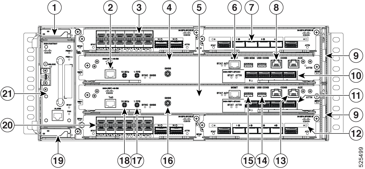
This chapter describes how to install the various components in the Cisco 8404-SYS-D router and includes the following sections:
Prerequisites
Before installing the Cisco 8404-SYS-D Router, it is important to prepare for the installation by:
Preparing the site (site planning) and reviewing the installation plans or method of procedures (MOP). For more information,
see the Prepare for Installation section.
Unpacking and inspecting the Cisco 8404-SYS-D Router
Gathering the tools and test equipment required to properly install the Cisco 8404-SYS-D Router
Install the router in a rack
The following sections describe how to install the Cisco 8404-SYS-D Router in a rack:
Procedure
Step 1
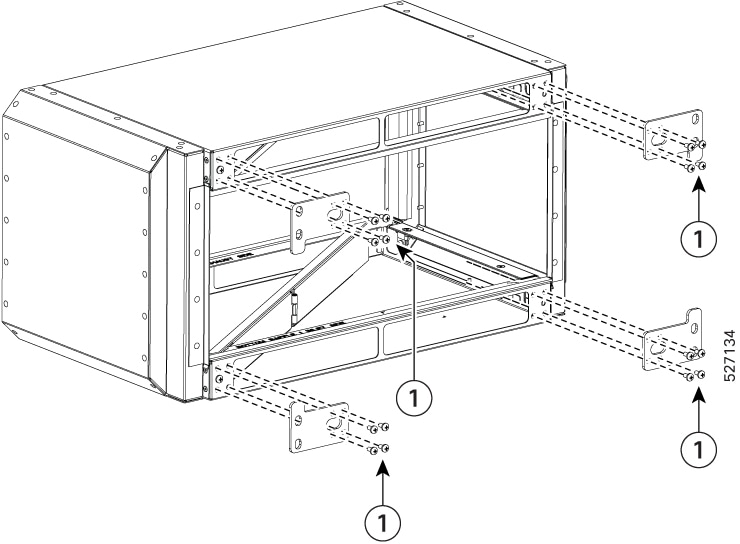
Remove the rack-mount brackets from the accessory kit and position them beside the router chassis.
Step 2
Position one of the brackets against the chassis side and align the screw holes.
Step 3
Secure the bracket to the chassis with the screws removed when performing Step 1. The recommended maximum torque is 6.2 in.-lb
(0.7 N-m).
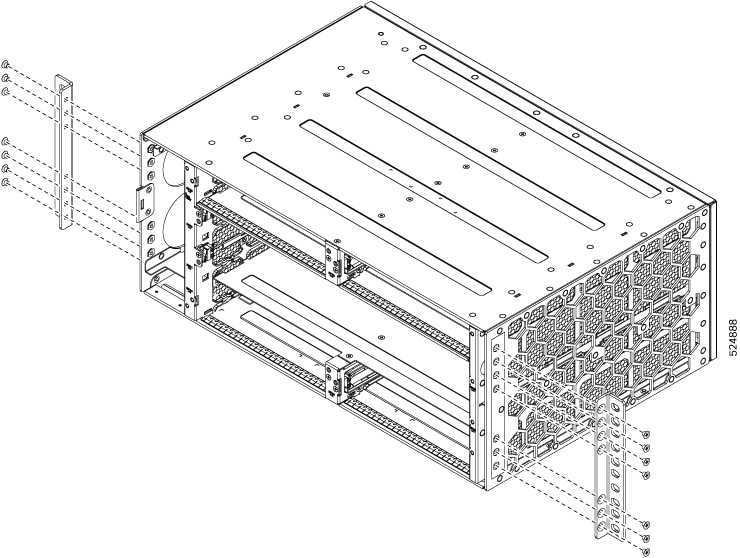
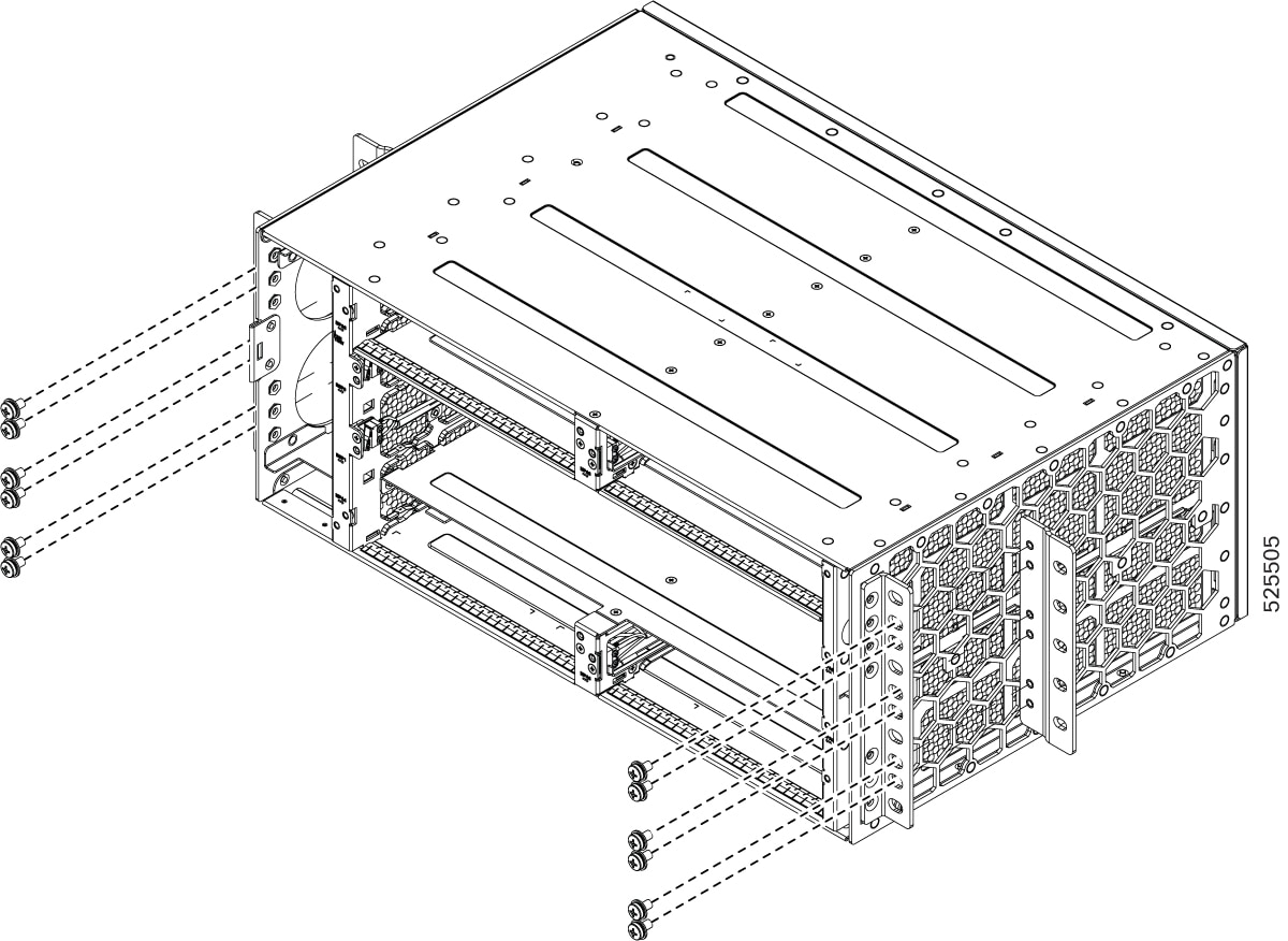
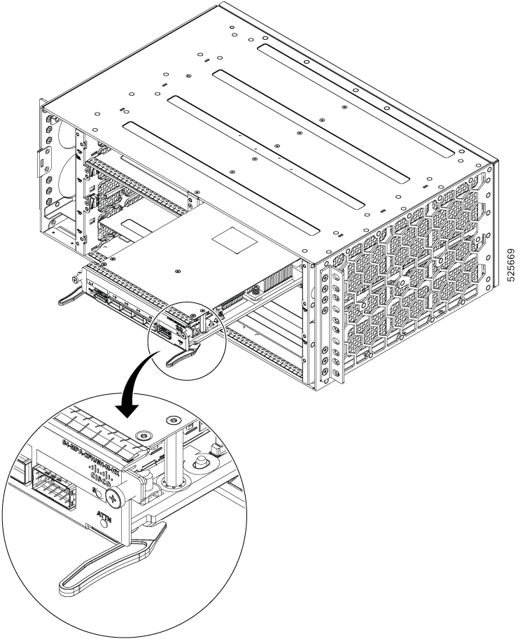
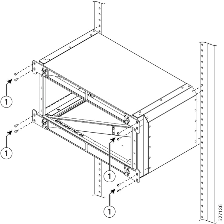
The following figures show how to attach the brackets on the Cisco 8404-SYS-D router for a ETSI rack and a 23-inch EIA rack.
Figure 1. Installing the Mounting Brackets for n ETSI Rack
Figure 2. Installing the Mounting Brackets for the 23-inch EIA Rack
Step 4
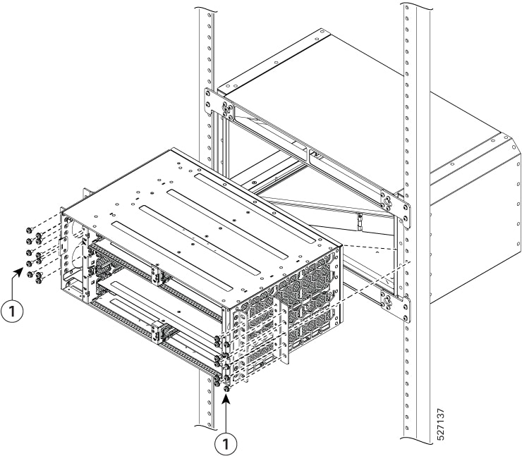
Position the chassis in the rack as follows:
If the front of the chassis (front panel) is at the front of the rack, insert the rear of the chassis between the mounting
posts.
If the rear of the chassis is at the front of the rack, insert the front of the chassis between the mounting posts.
Step 5
Align the mounting holes in the bracket with the mounting holes in the equipment rack.
Do not use module ejector lever as handles to lift the modules.
Note
The router can be mounted in an ETSI rack but the required bend radius for the cables and fibers within the 300 mm ETSI specification
cannot be maintained.
If you want to mount the router in ETSI cabinets, you need to have a custom-made cabinet front door to meet the fiber bend
radius requirement.
Step 6
Install chassis using 12 no rack screws. These screws can be arranged based on the rack used.
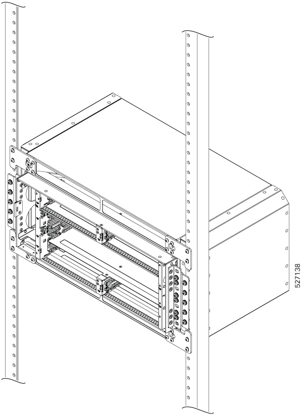
Step 7
Use a tape measure and level to verify that the chassis is installed straight and level.
Install the chassis ground connection
Before you connect the power or turn on the power to the Cisco 8404-SYS-D Router, you must provide an adequate chassis ground
(earth) connection to your router.
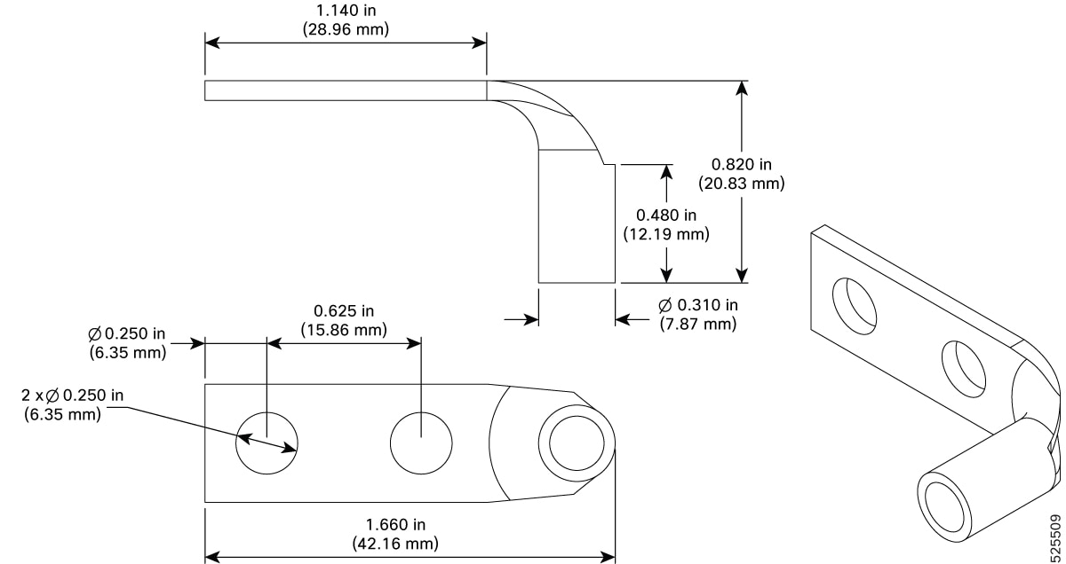
This section describes how to ground the Cisco 8404-SYS-D Router. The router provides two locations for attaching a 2-hole
grounding lug according to the rack-mounting brackets you use to install the router.
Figure 3. Attaching a Grounding Lug to the rear of the Router
Figure 4. Grounding Lug Dimensions
To ensure that the chassis ground connection that you provide is adequate, you need the following parts and tools:
Ratcheting torque screwdriver with Phillips head that exerts up to 20 in.-lb (2.25 N-m) of pressure for attaching the ground
wire to the router
Caution
Ensure that you secure the lugs only with the Cisco-provided screw or a Phillips head screw with an integrated washer of 10-32
x 0.3125 inch. Secure the screws only while assembling the lugs.
Crimping tool as specified by the ground lug manufacturer
6 AWG or larger copper wire for the ground wire
Wire-stripping tools appropriate to the wire you are using
Caution
Before making connections to the Cisco 8404-SYS-D Router, ensure that you disconnect the power at the circuit breaker. Otherwise,
severe injury to you or damage to the router may occur.
Warning
This equipment must be grounded. Never defeat the ground conductor or operate the equipment in the absence of a suitably
installed ground conductor. Contact the appropriate electrical inspection authority or an electrician if you are uncertain
that suitable grounding is available. Statement 1024
Warning
Use copper conductors only. Statement 1025
Warning
When installing the unit, the ground connection must always be made first and disconnected last. Statement 42
This unit is to be installed in a restrictive access location and must be permanently grounded to minimum 6 AWG copper ground
wire.
Perform the following procedure to ground the router using a 2-hole lug and the corresponding mounting point. Most carriers
require a minimum 6 AWG ground connection. Verify your carrier’s requirements for the ground connection.
Procedure
Step 1
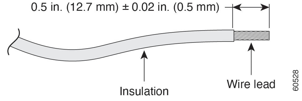
If your ground wire is insulated, use a wire-stripping tool to strip the ground wire to 0.5 inch ± 0.02 inch (12.7 mm ±0.5
mm) As shown in the figure below.
Figure 5. Stripping a Ground Wire
Step 2
Slide the open end of your 2-hole ground lug over the exposed area of the ground wire.
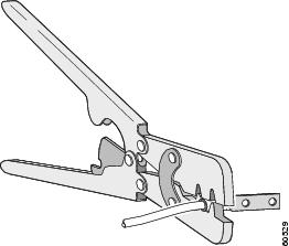
Step 3
Using a crimping tool (as specified by the ground lug manufacturer), crimp the ground lug to the ground wire as shown in
figure below.
Figure 6. Crimping a Ground Lug onto the Ground Wire
Step 4
Use a Phillips head screwdriver to attach the 2-hole ground lug and wire assembly to the router with the 2 pan-head Phillips
head screws. For all racks, attach the 2-hole ground lug to the rear of the router.
Step 5
Connect the other end of the ground wire to a suitable grounding point at your site.
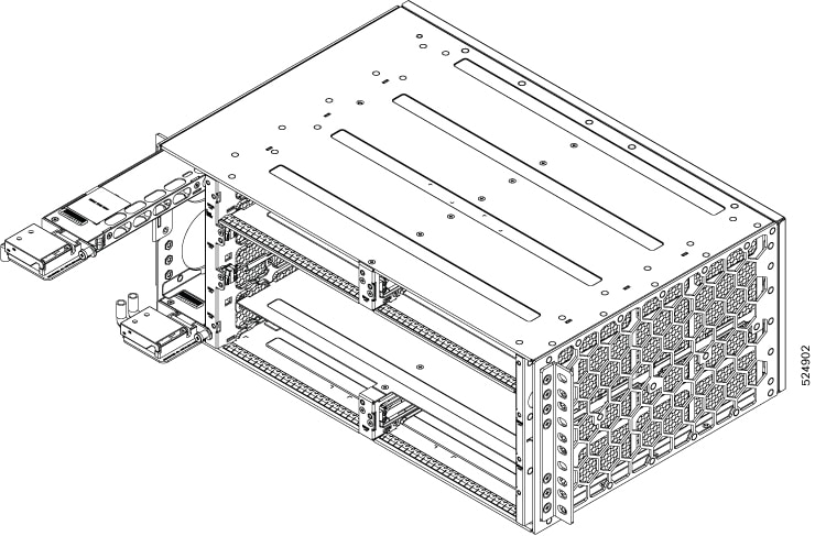
Attach the cable management brackets
The router supports the following bracket:
8404-CBLMGMT—This bracket helps in routing the cables from the interface modules, router switch processors (RSPs), and PEM
units; thereby enabling a proper cable bending radius.
Note
You can install the cable brackets along with the rack mount screws while installing the chassis. Or, you can install the
cable brackets after the chassis is monted on the rack. However, ensure the brackets are positioned such that they aid cable
routing and provide enough slack for fan trays and air filter removal.
Procedure
Step 1
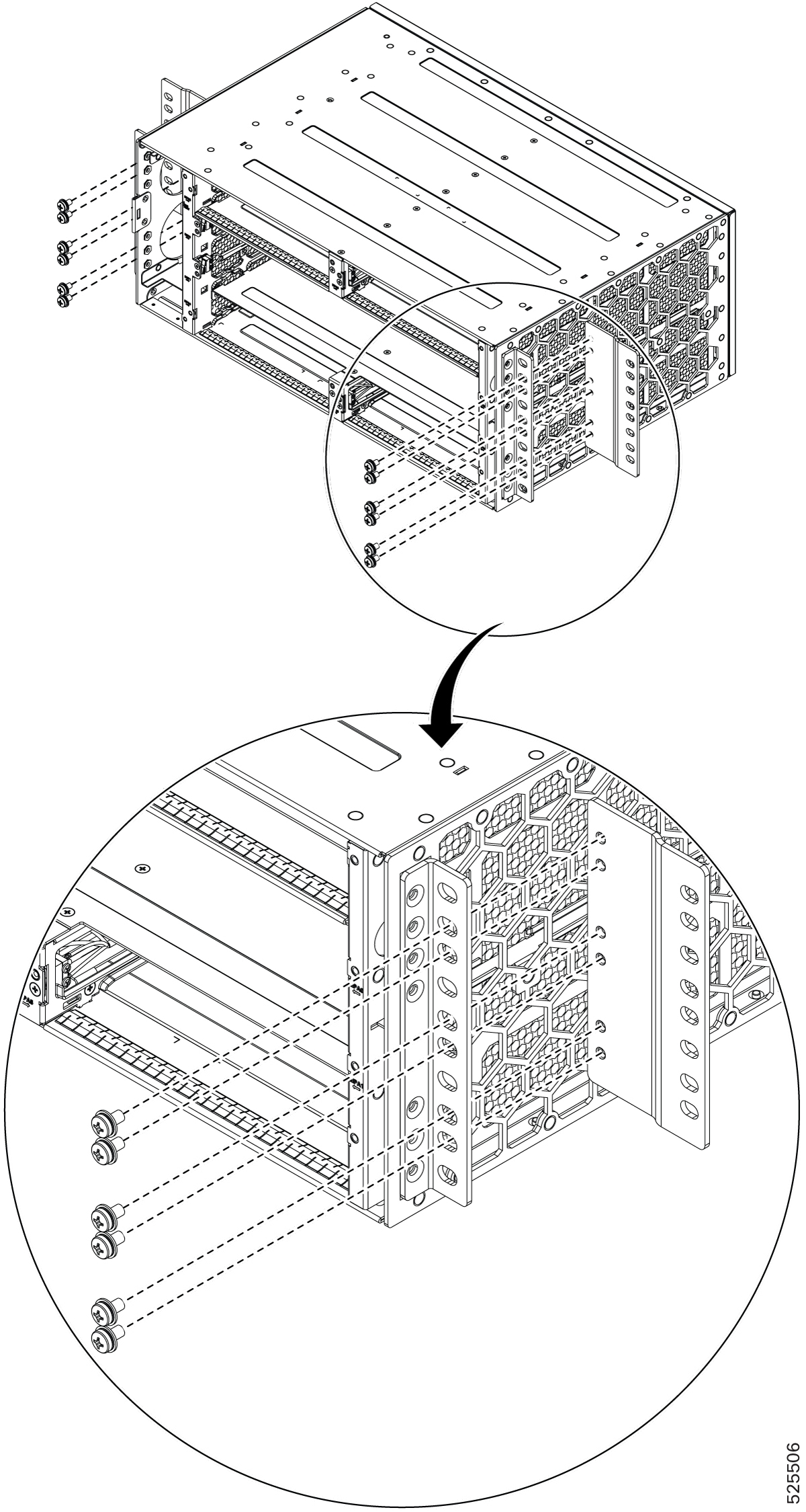
Position the cable management brackets against the front of the chassis and align the four screw holes, as shown in the figure
below.
Figure 7. Attaching Cable Management Brackets to the 19-inch Rack
Step 2
Secure the cable management brackets with four M4 screws. The recommended maximum torque is 10 in.-lb (1.12 N-m).
Install MPA
There are four MPA slots: slots 2, 3 at the chassis top and slots 4,5 on the bottom side of the chassis.
To install an MPA module in the router chassis, perform the following steps:
Procedure
Step 1
Slip on the ESD-preventive wrist strap that was included in the accessory kit.
Step 2
Choose a slot for the module. Make sure that there is enough clearance to accommodate any equipment that will be connected
to the ports on the module. If a blank module filler plate is installed in the slot in which you plan to install the module,
remove the plate by removing its 2 Phillips pan-head screws.
Step 3
Fully open both the ejector levers on the new module.
Caution
To prevent ESD damage, handle modules by carrier edges only.
Step 4
Position the module in the slot. Make sure that you align the sides of the module with the guides on each side of the slot,
as shown in the figure below.
Figure 8. MPA Installation
Step 5
Carefully slide the module into the slot until the EMI gasket on the module makes contact with the module in the adjacent
slot and both the ejector levers have closed to approximately 45 degrees with respect to the module faceplate.
Caution
If the top slot already has an MPA module installed, and you install a second MPA module in the slot below it, be careful
not to damage the EMI gasket of the bottom MPA module against the ejector levers of the top MPA during insertion.
Step 6
While pressing down, simultaneously close both the ejector levers to fully seat the module in the backplane connector. The
ejector levers are fully closed when they are flush with the module faceplate.
Step 7
Tighten the two captive installation screws on the module. The recommended maximum torque is 5.5 in.-lb (.62 N-m).
Note
Make sure that the ejector levers are fully closed before tightening the captive installation screws.
Step 8
Tighten the captive screw within three minutes after the full insertion of the card. After three 3 minutes, the card will
be shown as shutdown. Reload the chassis with the force option using the reload location command to bring the card to the operational mode.
RP/0/RP0/CPU0:ios##reload location 0/<slot #> force
Step 9
Verify that the captive installation screws are tightened on all of the modules installed in the chassis. This step ensures
that the EMI gaskets on all the modules are fully compressed in order to maximize the opening space for the new or replacement
module.
Note
If the captive installation screws are loose, the EMI gaskets on the installed modules will push adjacent modules toward
the open slot, which reduces the size of the opening and makes it difficult to install the new module.
Note
When installing the cabling to an MPA, we recommend that you leave a service loop of extra cabling sufficient to allow for
fan tray removal.
Note
Close all unused optics ports on the MPA module using the appropriate dust caps to prevent dust from accumulating inside the
cage. For information on dust caps, see the Installing dust caps.
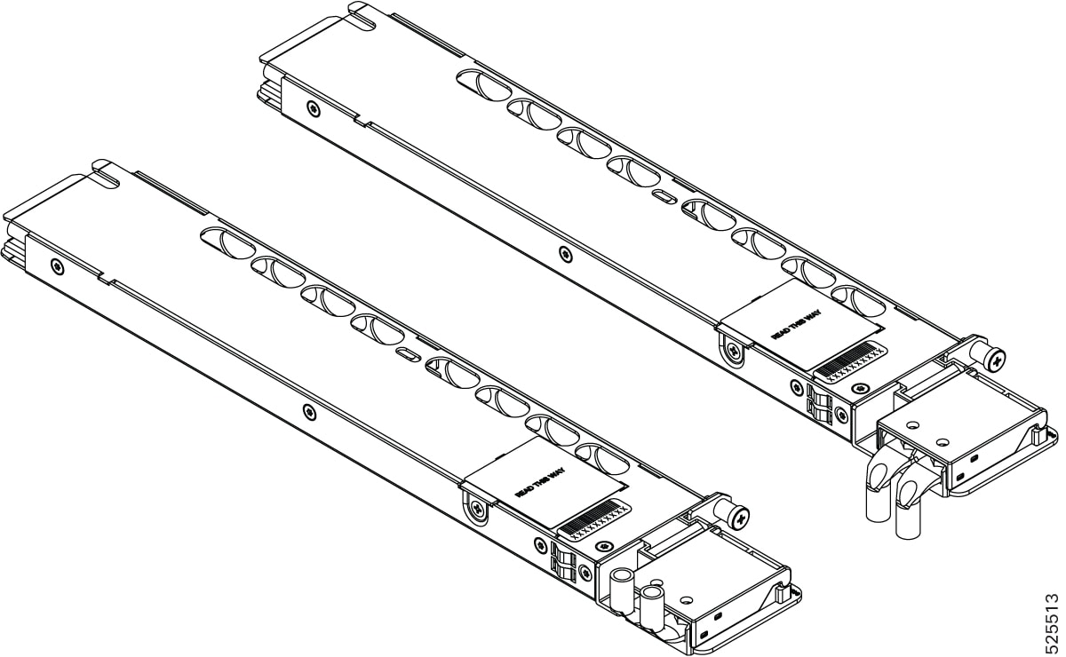
Install PEM
On the chassis above and below fan tray, there are two slots for the DC PEM card. PEM1 at bottom of fan tray and PEM0 on top
of the tray. The chassis is shipped with the PEMs installed .
This procedure provides steps required to install a PEM on the slot.
Figure 9. PEM
Procedure
Step 1
Slip on the ESD-preventive wrist strap that was included in the accessory kit.
Step 2
Choose a slot for the module.Position the module in the slot. Ensure that you align the sides of the module with the guides
on each side of the slot, as shown in the figure below.
Step 3
Slide the module carefully into the slot until the EMI gasket on the module makes contact with the chassis and the captive
screws on both sides of the module are aligned with the chassis screw holes.
Step 4
Tighten the captive screws.The recommended maximum torque is <Value> . Ensure that the EMI gaskets are fully compressed.
Note
The chassis gets its DC power from the PEM's. To connet the DC power to PEM's, see Install the DC Power Cables. Ensure that the PEM is powered from the right DC source and maintained within the operating voltage range as specificed
in the Table 2. DC Power Entry Module Specifications.
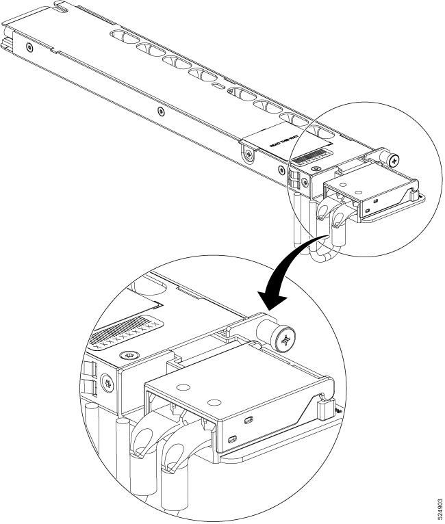
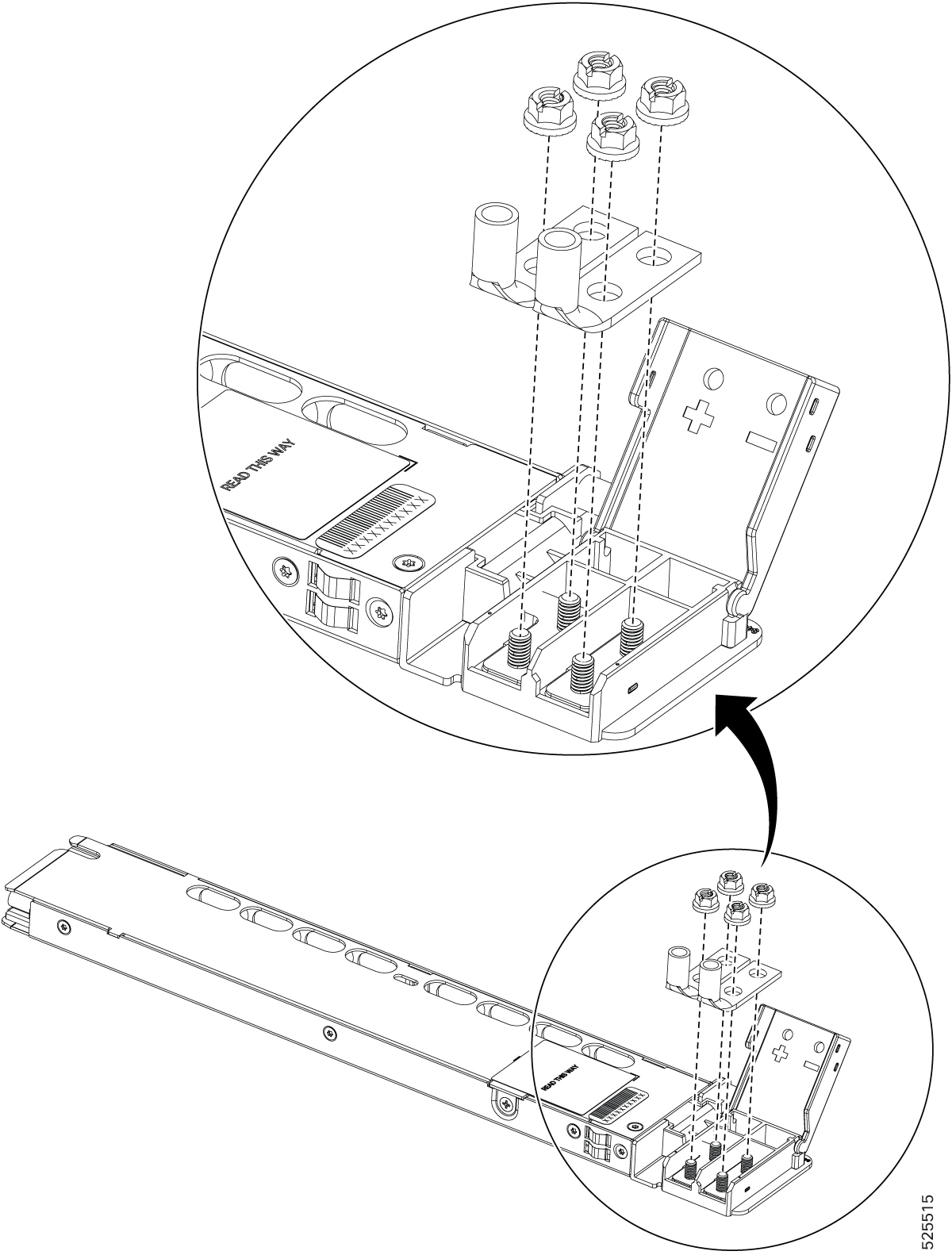
Install the DC PEM Cables
Note
When installing DC PEM, use 6AWG for longer cables and 8AWG for shorter cables, 90°C temperature rated cable. The recommended
cable length is three meters maximum from source.
Note
Always ensure that the building’s installation for short-circuit (overcurrent) protection does not exceed 60A.
We recommend you to use a circuit breaker or a fast acting fuse with a maximum DC rating, based on the router variants for
over current protection.
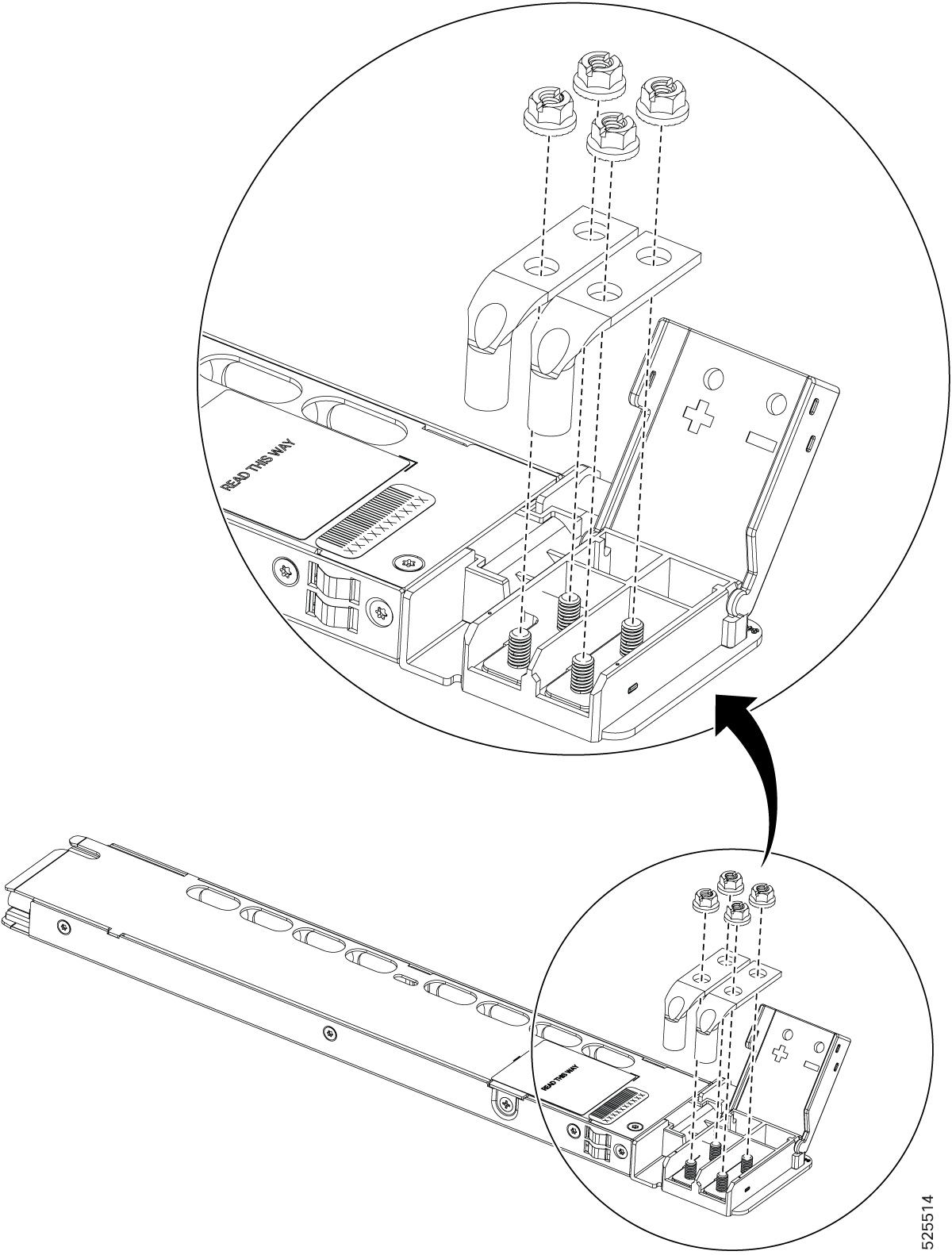
Note
We recommend that you do not install the lugs while the PEM is mounted on the chassis. First, remove the PEM from the chassis
to ensure safe and proper handling. With the PEM removed, attach the lugs securely to the PEM. After the lugs are attached
and all connections are secure, insert the PEM back into the chassis carefully.
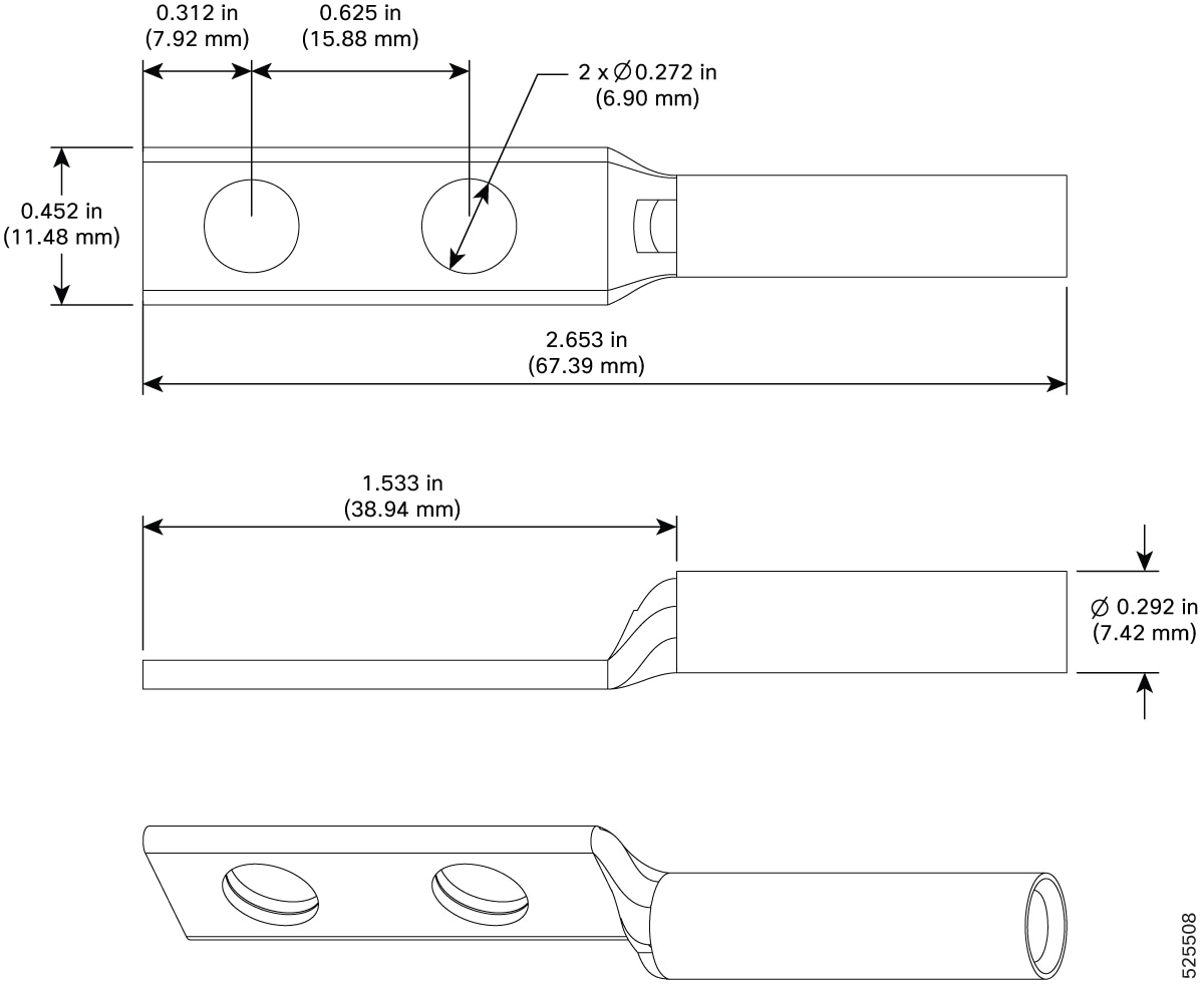
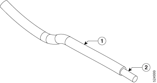
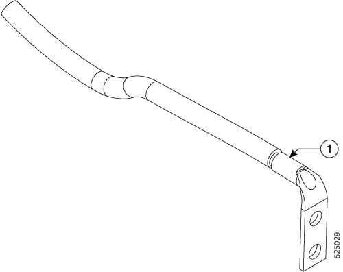
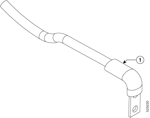
Figure 10. DC Lug Dimensions
To attach the DC PEM:
Locate the terminal block plug.
Insert the DC-input power source wires into the terminal block plug.
Attach the DC supply wires using the designated screws.
Use a ratcheting torque screwdriver to torque the terminal block plug captive screw. (See the following figure.)
Figure 11. DC PEM
Figure 12. DC PEM
Turn On a DC PEM
Perform the following procedure to activate a DC PEM:
Verify the PEM operation by checking whether the respective PEM front panel LED (PS0 or PS1) is green.
If the LEDs indicate any issues with power problem, see LEDs.
If you are also connecting a redundant DC PEM, repeat these steps for the second power source.
Note
If you are connecting a redundant DC PEM, ensure that each PEM is connected to a separate power source in order to prevent
power loss in the event of a power failure.
The operating voltage range is -40V to 72VDC, 45A maximum.
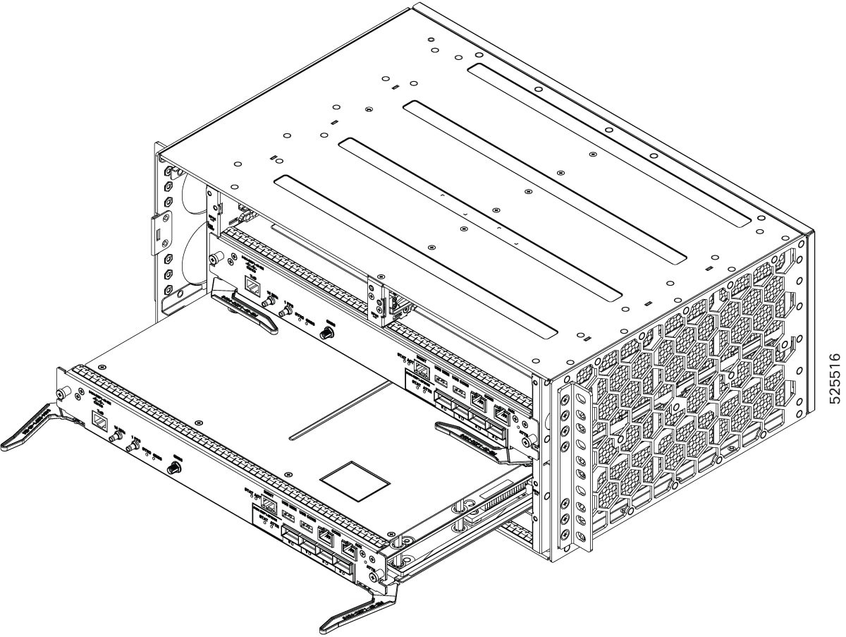
Install an RSP module
To install an RSP module in the router chassis, perform the following steps:
Procedure
Step 1
Slip on the ESD-preventive wrist strap that was included in the accessory kit.
Step 2
Choose a slot for the module. Make sure that there is enough clearance to accommodate any equipment that will be connected
to the ports on the module. If a blank module filler plate is installed in the slot in which you plan to install the module,
remove the plate by removing its 2 Phillips pan-head screws.
Step 3
Fully open both the ejector levers on the new module.
Caution
To prevent ESD damage, handle modules by carrier edges only.
Step 4
Position the module in the slot. Make sure that you align the sides of the module with the guides on each side of the slot,
as shown in the figure below.
Figure 13. RSP Installation
Step 5
Carefully slide the module into the slot until the EMI gasket on the module makes contact with the module in the adjacent
slot and both the ejector levers have closed to approximately 45 degrees with respect to the module faceplate.
Caution
If the top slot already has an RSP module installed, and you install a second RSP module in the slot below it, be careful
not to damage the EMI gasket of the bottom RSP module against the ejector levers of the top RSP during insertion.
Step 6
While pressing down, simultaneously close both the ejector levers to fully seat the module in the backplane connector. The
ejector levers are fully closed when they are flush with the module faceplate.
Step 7
Tighten the two captive installation screws on the module. The recommended maximum torque is 5.5 in.-lb (.62 N-m).
Note
Make sure that the ejector levers are fully closed before tightening the captive installation screws.
Note
After inserting the card completely, ensure that the captive screw is tightened within 3 minutes.
If the screw is not tightened within the specified time, the card will transition to a shutdown state.
To recover the card and bring it back to operational mode, you will need to manually execute the reload location command with the force option.
RP/0/RP0/CPU0:ios#reload location 0/RP0-1/<slot #> force
Step 8
Tighten the captive screw within three minutes after the full insertion of the card. After three 3 minutes, the card will
be shown as shutdown. Reload the chassis with the force option using the reload location command to bring the card to the operational mode.
RP/0/RP0/CPU0:ios##reload location 0/<slot #> force
Step 9
Verify that the captive installation screws are tightened on all of the modules installed in the chassis. This step ensures
that the EMI gaskets on all the modules are fully compressed in order to maximize the opening space for the new or replacement
module.
Note
If the captive installation screws are loose, the EMI gaskets on the installed modules will push adjacent modules toward
the open slot, which reduces the size of the opening and makes it difficult to install the new module.
Note
When installing the cabling to an RSP, we recommend that you leave a service loop of extra cabling sufficient to allow for
fan tray removal.
Note
Close all unused optics ports on the MPA module using the appropriate dust caps to prevent dust from accumulating inside the
cage. For information on dust caps, see the Installing dust caps.
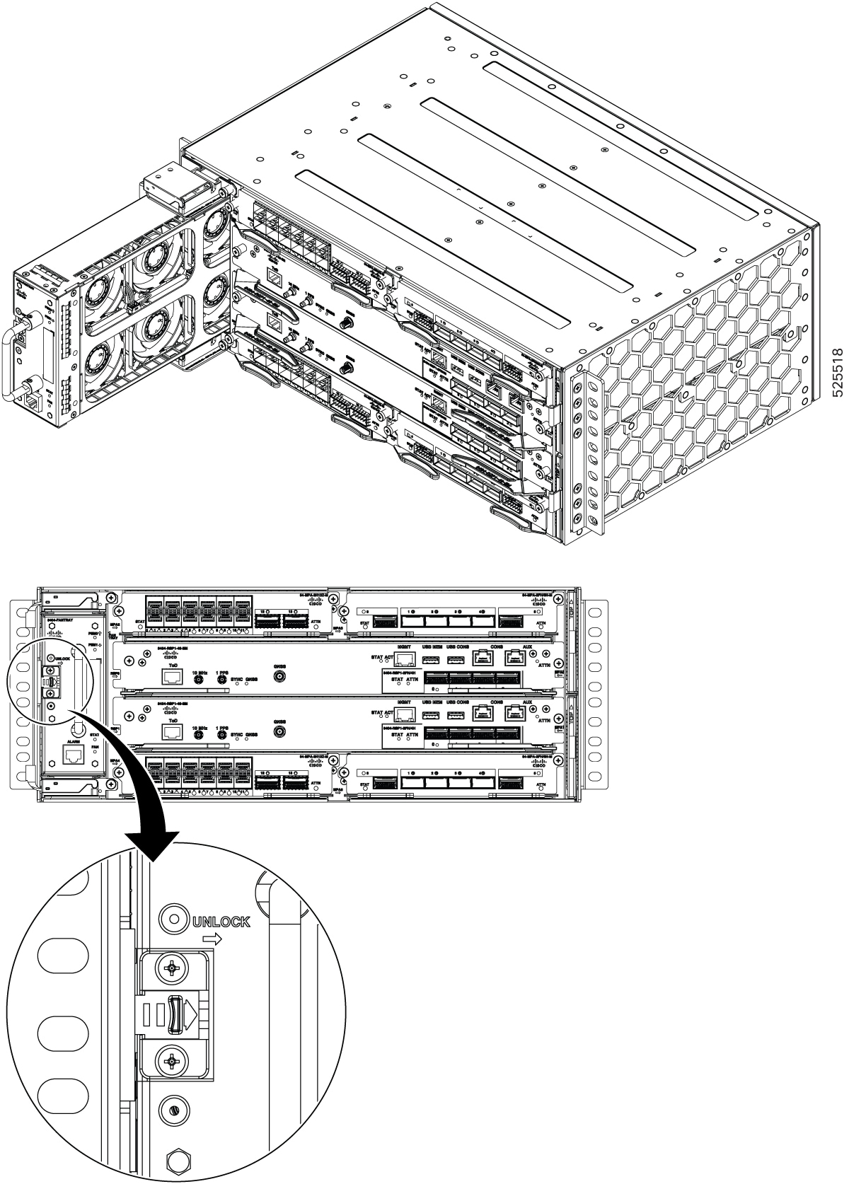
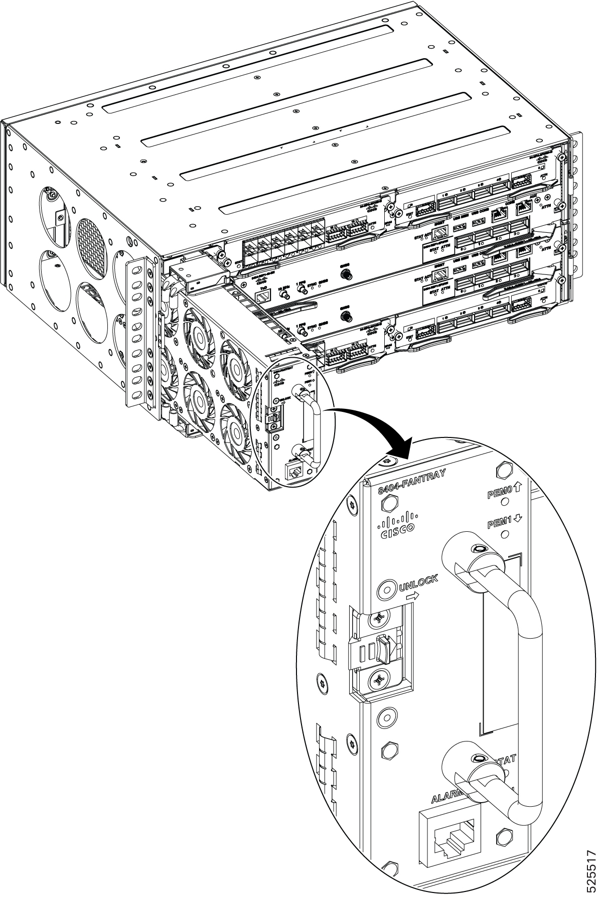
Install the fan tray
The fan tray is a modular unit that provides cooling to the Cisco 8404-SYS-D router.
Note
Do not introduce
body parts or objects in the fan tray slot when installing or removing the fan
tray module. Exposed circuitry is an energy hazard.
Follow these steps to install the primary fan tray in the chassis:
Procedure
Step 1
Slip on the ESD-preventive wrist strap that was included in the accessory kit.
Step 2
Orient the fan tray so that the latch is on the left side of the fan tray’s front panel. The figure below shows how to orient
the fan tray.
Figure 14. Install the Fan Tray
Step 3
Guide the fan tray into the chassis using the front handle and thumb finger to move the latch position to the right.
Caution
The fan is exposed on the right side of the fan tray. Keep your fingers, clothing, and jewellery away from the fans. Always
handle the fan tray by the handle.
Step 4
After the fan tray is fully seated in the chassis, release the latch carefully to ensure that the latch is fully locked.
Air filter maintenance
A periodic health check of the filter, every 3 months based on the level of air in the environment, helps in avoiding over
clogging of the filters and provides a better life. This product's filter is used as a single-use component. If the product
is installed in a controlled environment, check and replace the filter every three months, otherwise replace the filter every
month with PID (Cisco 8404-FILTER) or equivalent.
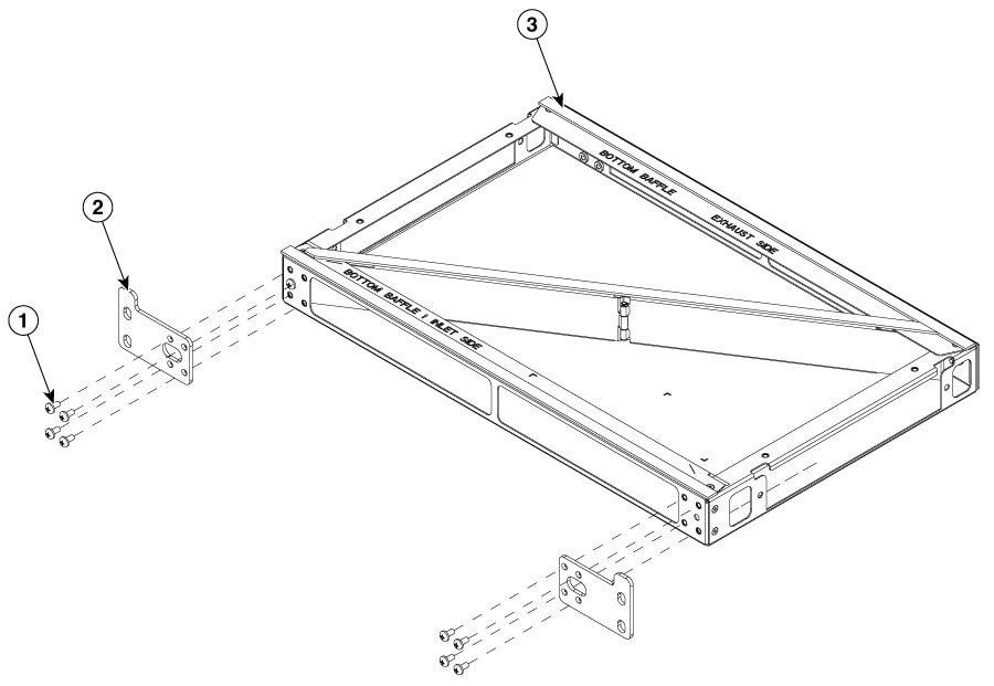
Install the air plenum (8K-4RU-F2B-AIR)
The Cisco air plenum kit maintains optimal hardware temperatures by efficiently managing airflow and directing exhaust.
Installation is flexible, allowing for air plenum deployment from either the front or the rear of the rack depending on your
site access requirements.
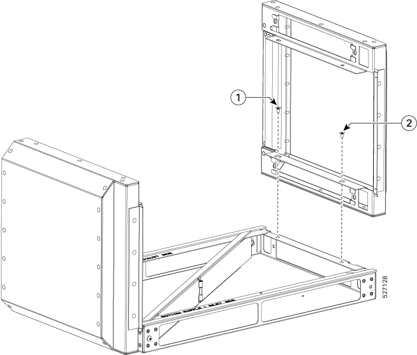
Install air plenum assembly (8K-4RU-F2B-AIR) (only with front side rack access)
Use this procedure to install air plenum (8K-4RU-F2B-AIR) from the front side of the rack.
Procedure
Step 1
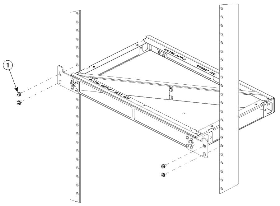
Attach rack mounting brackets to the base of the plenum.
Figure 15. Air plenum base
Note
Ensure that you select 19-inches, 21-inches, or 23-inches adapter for the plenum based on your rack size.
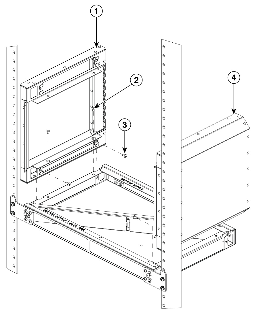
Step 2
Fix the base of the plenum in the rack.
Figure 16. Air plenum base with rack
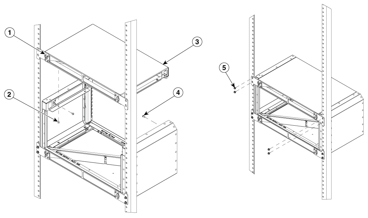
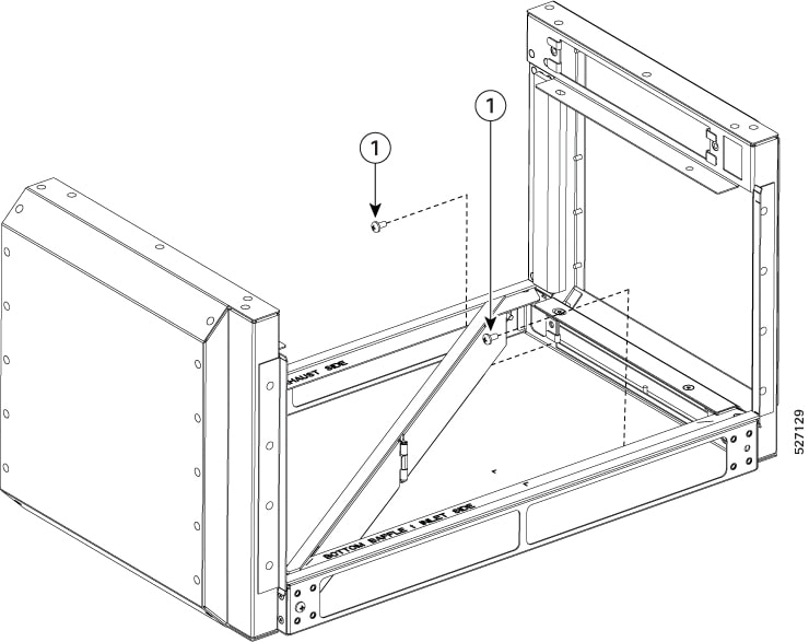
Step 3
Fix air baffle on both sides of the rack from the base of plenum.
Figure 17. Attach air baffle on both sides of rack from base of air plenum
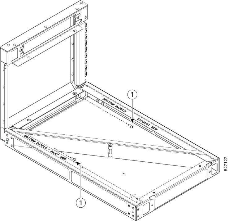
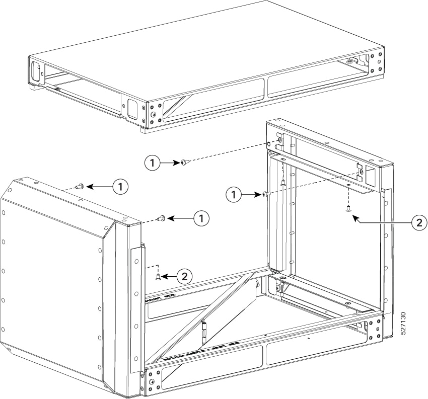
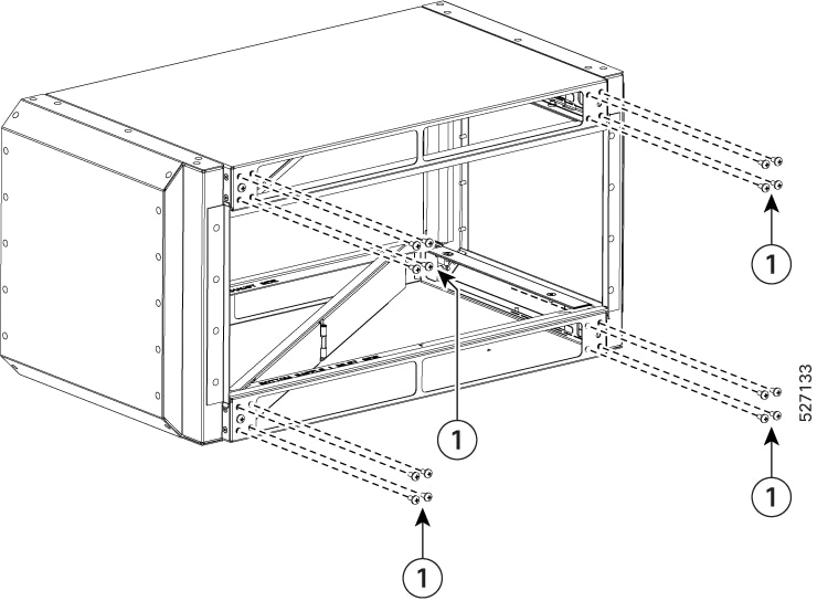
Step 4
Repeat step 1 and step 2 to complete the plenum assembly on the top side of the plenum base.
Figure 18. Assembled air plenum
Part No
Part Description
Quantity
1
Flat-head M4 screw
(48-101783-XX)
8
2
Pan-head M4 screw
(48-0398-XX)
24
3
Base Plenum
(800-51957-XX)
1
4
Left Baffle
(800-51963-XX)
1
5
Right Baffle
(800-51964-XX)
1
6
Top Plenum
(800-51965-XX)
1
7
Rack Screw
8
8
Rack Plenum Bracket
4
9
Router Unit
1
Install air plenum (8K-4RU-F2B-AIR) assembly (optional with rear side rack access)
You can use this procedure if you have access to assemble the air plenum from the rear side of the rack and the depth of the
rack is more than 500 mm.
Procedure
Step 1
Prepare the air plenum assembly box.
Figure 19. Air plenum assembly box
Part No
Description
1
Pan-head M4 screw
2
Flat-head M4 screw
Step 2
Attach the rack-mount bracket to the air plenum assembly box.
Figure 20. Air plenum assembly box with rack-mount bracket
Step 3
Attach the air plenum assembly box to the rack.
Figure 21. Air plenum assembly box in a rack
Install the chassis in the air plenum (8K-4RU-F2B-AIR)
Note
Ensure that the router is not installed in the air plenum while mounting it on the rack.
For instructions on mounting the air plenum on the rack.
Procedure
Step 1
Position the chassis so that the rear of the chassis is at the front of the plenum.
Figure 22. Installing chassis in air plenum
Step 2
Slide the chassis into the plenum so that the front of the chassis is in flush with the mounting rails and brackets.
Figure 23. Chassis with air plenum
Install dust caps
The following list provides the product IDs (PIDs) for the dust caps that are available for each port type:
A900-DCAP-RJ45
A900-DCAP-SFP
A900-DCAP-USB
8000-QSFP-DCAP
RJ-45—A900-DCAP-RJ45-S= (24 dust caps per package) or A900-DCAP-RJ45-L= (240 caps per package)
SFP—A900-DCAP-SFP-S= (24 caps per package) or A900-DCAP-SFP-L= (240 caps per package)
USB—A900-DCAP-USB-S= (12 dust caps per package) or A900-DCAP-USB-L= (120 dust caps per package)
To install the dust cap:
Hold the dust cap by its handle.
Insert the dust cap in to the appropriate unused ports (RJ-45, SFP, USB, or QSFP) on the chassis front panel.
Install and remove SFP modules
The Cisco 8404-SYS-D router supports a variety of SFP modules, including optical and Ethernet modules. For information on
how to install and remove SFP modules, see the documentation for the SFP module at
We recommend that you wait 30 seconds between removal and insertion of an MPA and RSP on an interface module. This time is
recommended to allow the transceiver software to initialize and synchronize with the standby RSP. Changing an SFP more quickly
could result in transceiver initialization issues that disable the SFP.
Warning
Only trained and qualified personnel should be allowed to install, replace, or service this equipment. Statement 1030
Warning
There are no serviceable parts inside. To avoid risk of electric shock, do not open. Statement 1073
Warning
An instructed person is someone who has been instructed and trained by a skilled person and takes the necessary precautions
when working with equipment.
A skilled person or qualified personnel is someone who has training or experience in the equipment technology and understands
potential hazards when working with equipment. Statement 1089
Warning
Only a skilled person should be allowed to install, replace, or service this equipment. Refer to statement 1089 for the definition
of a skilled person. Statement 1090
Warning
Only an instructed person or skilled person should be allowed to install, replace, or service this equipment. See statement
1089 for the definition of an instructed or skilled person. Statement 1091
Warning
Hot surface. Use care when handling. Statement 1092
Depending on the chassis, you can use Quad Small Form-Factor Pluggable Plus (QSFP+), QFSP-DD, QSFP28, SFP, SFP+, and RJ45
connectors to connect the ports on the line cards to other network devices.
To prevent damage to the fiber-optic cables, we recommend that you keep the transceivers
disconnected from their fiber-optic cables when installing the transceiver in the line
card. Before removing a transceiver from the router, remove the cable from the
transceiver.
To maximize the effectiveness and life of your transceivers and optical cables, do the following:
Wear an ESD-preventative wrist strap that is connected to an earth ground whenever handling transceivers. The router is typically
grounded during installation and provides an ESD port to which you can connect your wrist strap.
Do not remove and insert a transceiver more often than is necessary. Repeated removals and insertions can shorten its useful
life.
Keep the transceivers and fiber-optic cables clean and dust free to maintain high signal accuracy and to prevent damage to
the connectors. Attenuation (loss of light) is increased by contamination and should be kept below 0.35 dB.
Clean these parts before installation to prevent dust from scratching the fiber-optic cable ends.
Clean the connectors regularly; the required frequency for cleaning depends upon the
environment. In addition, clean connectors when they are exposed to dust
or accidentally touched. Both wet and dry cleaning techniques can be
effective; refer to your site's fiber-optic connection cleaning
procedures.
Do not touch the ends of connectors. Touching the ends can leave fingerprints and cause other contamination.
Inspect routinely for dust and damage. If you suspect damage, clean and then inspect fiber ends under a microscope to determine
if damage has occurred.
Connect to the Console Port
The router must be fully installed in its rack, connected to a power source, and grounded.
The necessary cabling for the console, management, and network connections must be available.
An RJ45 rollover cable and DB9F/RJ45 adapter are provided in the router accessory kit.
Network cabling should already be routed to the location of the installed router.
Before you create a network management connection for the router or connect the router to the network, you must create a local
management connection through a console terminal and configure an IP address for the router. You also can use the console
to perform the following functions (each of which can be performed through the management interface after you make that connection):
Configure the router using the command-line interface (CLI).
The system console port is an RJ45 receptacle for connecting a data terminal to perform the initial configuration of the
router. The console cable is shipped with the hardware.
Note
Only RJ45 to DB-9 adapter cable is provided in the package.
Figure 24. Connecting the USB Type-A Console Cable to the Chassis
1
USB Type-A console port
2
USB Type-A to USB Type-A cable
Follow this procedure to connect a data terminal to the console port:
Set your terminal to these operational values: 115200 bps, 8 data bits, no parity, and two stop bits.
Attach the terminal end of the cable to the interface port on the data terminal.
Attach the other end of the cable to the console port.
Connect to the Management Ethernet Port
You must complete the initial router configuration.
The management Ethernet port provides out-of-band management, which enables you to use the Command Line Interface (CLI) to
manage the router by its IP address. This port uses a 100/1000 Ethernet connection with an RJ45 interface.
Note
To prevent an IP address conflict, do not connect the management Ethernet port until the initial configuration is complete.
To connect cables to the system management port, attach Category 5 cables directly to the RJ45 receptacle on the management
Ethernet port.
Figure 25. Connect to the Management Ethernet Port
6
Management (MGMT) port
Note
To comply with GR-1089-CORE, the intra-building port(s) of the equipment must use shielded intra-building cabling or wiring
that is grounded at both ends.
Plug the cable directly into the RJ45 receptacle.
Connect the network end of your RJ45 cable to a switch, hub, repeater, or other external equipment.
Connecting Timing Cables
The following sections describe how to connect timing cables.
Connecting Cables to Timing Interfaces Card
Perform the following steps on how to connect cables from the router to a Timing Interfaces Card unit for input 10Mhz or 1PPS
interface.
Connect one end of a mini-coax cable to the Timing Interfaces Card unit.
Connect the other end of the mini-coax cable to the 10MHz or 1PPS port on the router.
Install and Remove Transceiver Module
This section shows how to install and remove transceiver module.
Safety precautions for module installation and removal
Be sure to observe the following safety precautions when you work on the chassis.
Install and Remove SFP Modules
Before you remove or install an SFP or SFP+ module, read the installation information in this section.
Caution
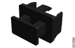
Protect all the unused ports by inserting clean dust covers or dust caps into them.
Caution
Protect the line card by inserting a clean SFP/SFP+ module cage cover (shown in the following figure) into the optical module
cage when there is no SFP or SFP+ module installed. The SFP/SFP+ module cage cover is not a standard part of the accessories
kit.
Figure 26. SFP/SFP+ Module Cage Cover
Caution
Protect the SFP or SFP+ modules by inserting clean dust covers into them after the cables are removed. Be sure to clean the
optic surfaces of the fiber cables before you plug them back into the optical ports of another module. Avoid getting dust
and other contaminants into the optical ports of your SFP or SFP+ modules, because the optics do not work correctly when obstructed
by dust.
Caution
We strongly recommend that you do not install or remove the SFP or SFP+ module with fiber-optic cables attached to it because
of the potential of damaging the cable, the cable connector, or the optical interfaces in the module. Disconnect all cables
before removing or installing an SFP or SFP+ module. Removing and inserting a module can shorten its useful life; so you should
not remove and insert modules more than it is absolutely necessary.
Note
When installing an SFP or SFP+ module, you would hear a click as the triangular pin on
the bottom of the module snaps into position into the hole in the receptacle. The click
indicates that the module is correctly seated and secured in the receptacle. Verify that the
modules are completely seated and secured in their assigned receptacles on the line card by
firmly pushing on each SFP or SFP+ module.
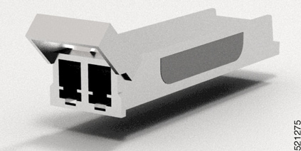
Bale Clasp SFP or SFP+ Module
The bale clasp SFP or SFP+ module has a clasp that you use to remove or install the
module. (See the figure below.)
Figure 27. Bale Clasp SFP or SFP+ Module
Install a Bale Clasp SFP or SFP+ Module
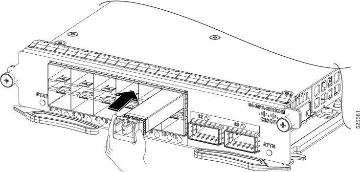
To install this type of SFP or SFP+ module:
Attach an ESD-preventive wrist or ankle strap and follow its instructions for use.
Close the bale clasp before inserting the SFP module.
Line up the SFP module with the port and slide it into the port. (See the figure below.)
Figure 28. Installing a Bale Clasp SFP Module into a Port
Note
When installing an SFP or SFP+ module, you should hear a click as the triangular pin on the bottom of the SFP module snaps
into the hole in the receptacle. This click indicates that the module is correctly seated and secured in the receptacle. Verify
that the SFP modules are completely seated and secured in their assigned receptacles on the line card by firmly pushing on
each SFP module.
Remove a Bale Clasp SFP or SFP+ Module
To remove this type of SFP or SFP+ module:
Attach an ESD-preventive wrist or ankle strap and follow its instructions for use.
Disconnect and remove all interface cables from the ports; note the current connections of the cables to the ports on the
line card.
Open the bale clasp on the SFP module with your index finger, as shown in the figure below. If the bale clasp is obstructed
and if you cannot open it, use your index finger, use a small flat-blade screwdriver or other long, narrow instrument to open
the bale clasp.
Grasp the SFP module between your thumb and index finger and carefully remove it from the port, as shown in the figure below.
Note
This action must be performed during your first instance. After all ports are populated, this may not be possible.
Figure 29. Removing a Bale Clasp SFP or SFP+ Module
Place the SFP module that you removed on an antistatic mat, or immediately place it in a static shielding bag if you plan
to return it to the factory.
Protect your line card by inserting a clean SFP module cage covers into the optical module cage when there is no SFP module
installed.
Connect Interface Ports
You can connect optical interface ports on line cards with other devices for network connectivity.
Connect a Fiber-Optic Port to the Network
Depending on the line card model that you are using, you can use either QSFP+ or QSFP28 transceivers. Some transceivers work
with fiber-optic cables that you attach to the transceivers and other transceivers work with pre-attached copper cables. When
installing fiber-optic cables for a port, you must install SFP transceivers for 1-Gigabit optical ports or install SFP+ transceivers
for 10-Gigabit optical ports or QSFP+ transceivers for 100-Gigabit ports before installing the fiber-optic cable in the transceivers.
Caution
Removing and installing a transceiver can shorten its useful life. Do not remove and insert
transceivers more than it is absolutely necessary. We recommended that you
disconnect cables before installing or removing transceivers to prevent damage
to the cable or transceiver.
Disconnect Optical Ports from the Network
When you need to remove fiber-optic transceivers, you must first remove the fiber-optic cables from the transceiver before
you remove the transceiver from the port.
Maintain Transceivers and Optical Cables
To maintain high signal accuracy and to prevent damage to the connectors, transceivers and
fiber-optic cables must be kept clean and free of dust. Attenuation (loss of light) is
increased by contamination and should be below 0.35 dB.
Transceivers are static sensitive. To prevent ESD damage, wear an ESD-preventative wrist strap that is connected to the grounded
chassis.
Do not remove and insert a transceiver more than it is necessary. Repeated removals and insertions can shorten its useful
life.
Keep all optical connections covered when not in use. Clean them before use to prevent dust from scratching the fiber-optic
cable ends.
Do not touch the ends of connectors. Touching the ends would leave fingerprints and cause other contamination.
Clean the connectors regularly; the required frequency of cleaning depends upon the environment. In addition, clean connectors
if they are exposed to dust or have been accidentally touched. Both wet and dry cleaning techniques can be effective; refer
to your site's fiber-optic connection cleaning procedures.
Inspect routinely for dust and damage. Clean and then inspect fiber ends under a microscope to determine whether any damage
has occurred.
Install and Remove QSFP Transceiver Modules
This section provides the installation, cabling, and removal instructions for the Quad Small Form-Factor Pluggable transceiver
modules. Refer to the Cisco Optical Transceiver Handling Guide for additional details on optical transceivers.
Caution
When inserting optical transceiver modules into host ports, handle them carefully. Ensure that the applied force does not
exceed 20 lbs (9.1kg).
Note
The router diagrams are provided for reference purposes only and may not represent the actual product.
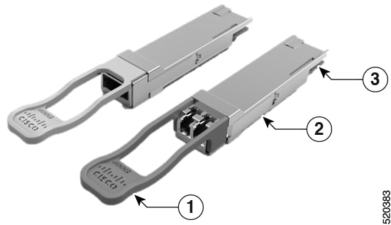
The following figure shows a 400-Gigabit QSFP-DD optical transceiver.
Figure 30. 400-Gigabit QSFP-DD Transceiver Module
1
Pull-tab
2
QSFP-DD transceiver body
3
Electrical connection to the module circuitry
Installing the Transceiver Module
Warning
This icon is a hot surface warning. To avoid personal injury, do not
touch without proper protection.
Caution
The transceiver module is a static-sensitive device. Always use an ESD wrist strap or similar individual grounding device
when handling transceiver modules or coming into contact with system modules.
Caution
Protect the transceiver ports by inserting clean dust caps (8000-QSFP-DCAP) into any ports not in use and do not have optical
modules plugged in. If optical modules are plugged in but not in use, the dust caps that were supplied with the optical modules,
should be used to protect the TX and RX surfaces of the optical module.
Be sure to clean the optic surfaces of the fiber cables before you plug them back into the optical ports of another module.
The router ships with dust caps plugged in. We highly recommend you to keep the dust caps plugged in until you are ready to
plug an optic.
The dust caps protect the ports from possible EMI interference and also avoid contamination due to dust collection. To meet
the EMI interference requirements, you must use the metal dust caps when the ports are not in use by optical modules.
The following table provides the supported port details and operating temperature of the QDD-400G-ZR-S and QDD-400G-ZRP-S
optical modules when port side exhaust or port side intake fans and power supplies are used.
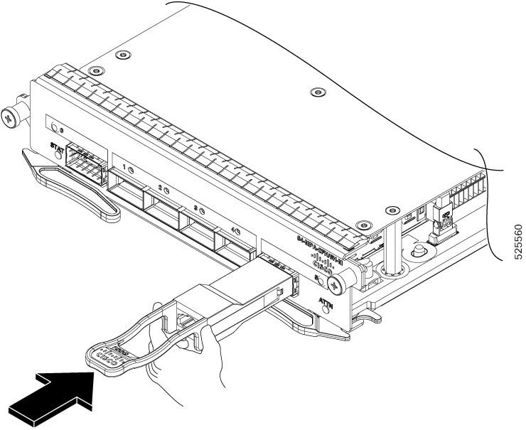
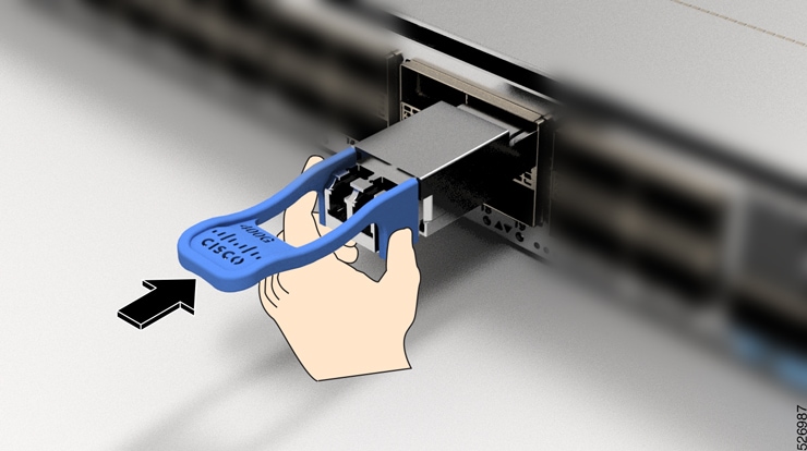
The QSFP transceiver module has a pull-tab latch. To install a transceiver module, follow these steps:
Procedure
Step 1
Attach an ESD wrist strap to yourself and a properly grounded point on the chassis or the rack.
Step 2
Remove the transceiver module from its protective packaging.
Step 3
Check the label on the transceiver module body to verify that you have the correct model for your network. Do not remove the
dust plug until you’re ready to attach the network interface cable. Dust plug is not shown in the images.
Step 4
Hold the transceiver by the pull-tab so that the identifier label is on the top.
Step 5
Align the transceiver module in front of the module’s transceiver socket opening and carefully slide the transceiver into
the socket until the transceiver contact with the socket electrical connector.
Figure 31. Installing the QSFP Transceiver Module
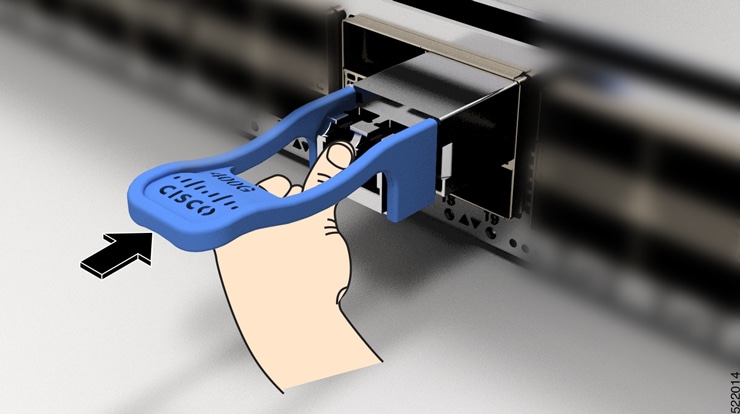
Step 6
Press firmly on the front of the transceiver module with your thumb to fully seat the transceiver in the module’s transceiver
socket (see the below figure).
Caution
If the latch isn’t fully engaged, you might accidentally disconnect the transceiver module.
Figure 32. Seating the QSFP Transceiver Module
Attach the Optical Network Cable
Before you begin
Before you remove the dust plugs and make any optical connections, follow these guidelines:
Keep the protective dust plugs installed in the unplugged fiber-optic cable connectors and in the transceiver optical bores
until you are ready to make a connection.
Inspect and clean the optical connector end faces just before you make any connections.
Grasp the optical connector only by the housing to plug or unplug a fiber-optic cable.
Note
The transceiver modules and fiber connectors are keyed to prevent incorrect insertion.
Note
The multiple-fiber push-on (MPO) connectors on the optical transceivers support network interface cables with either physical
contact (PC) or ultra-physical contact (UPC) flat polished face types. The MPO connectors on the optical transceivers do not
support network interface cables with an angle-polished contact (APC) face type.
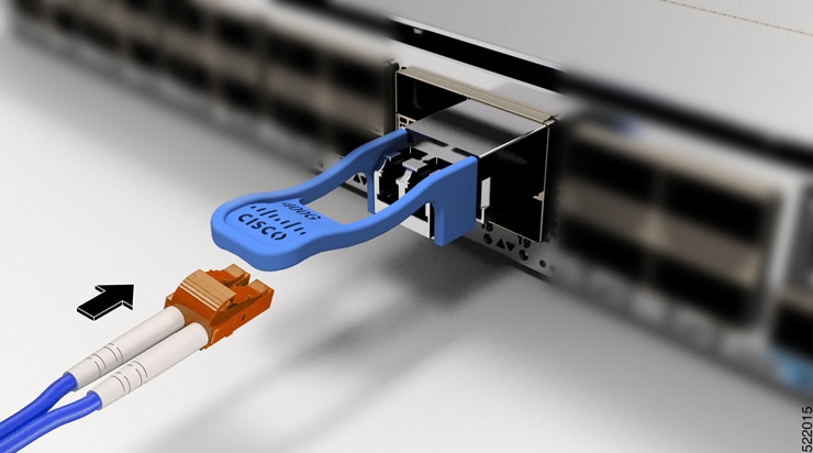
Remove the dust plugs from the optical network interface cable MPO connectors and from the transceiver module optical bores.
Save the dust plugs for future use.
Step 2
Attach the network interface cable MPO connectors immediately to the transceiver module.
Figure 33. Cabling a Transceiver Module
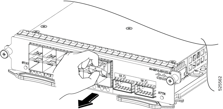
Removing the Transceiver Module
Caution
The transceiver module is a static-sensitive device. Always use an ESD wrist strap or similar individual grounding device
when handling transceiver modules or coming into contact with modules.
To remove a transceiver module, follow these steps:
Procedure
Step 1
Disconnect the network interface cable from the transceiver connector.
Step 2
Install the dust plug immediately into the transceiver’s optical bore.
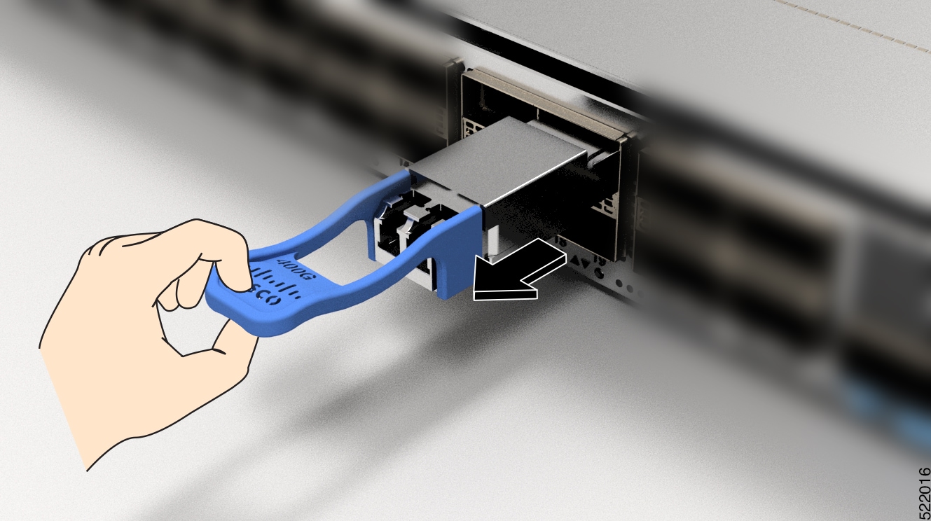
Step 3
Grasp the pull-tab and gently pull to release the transceiver from the socket.
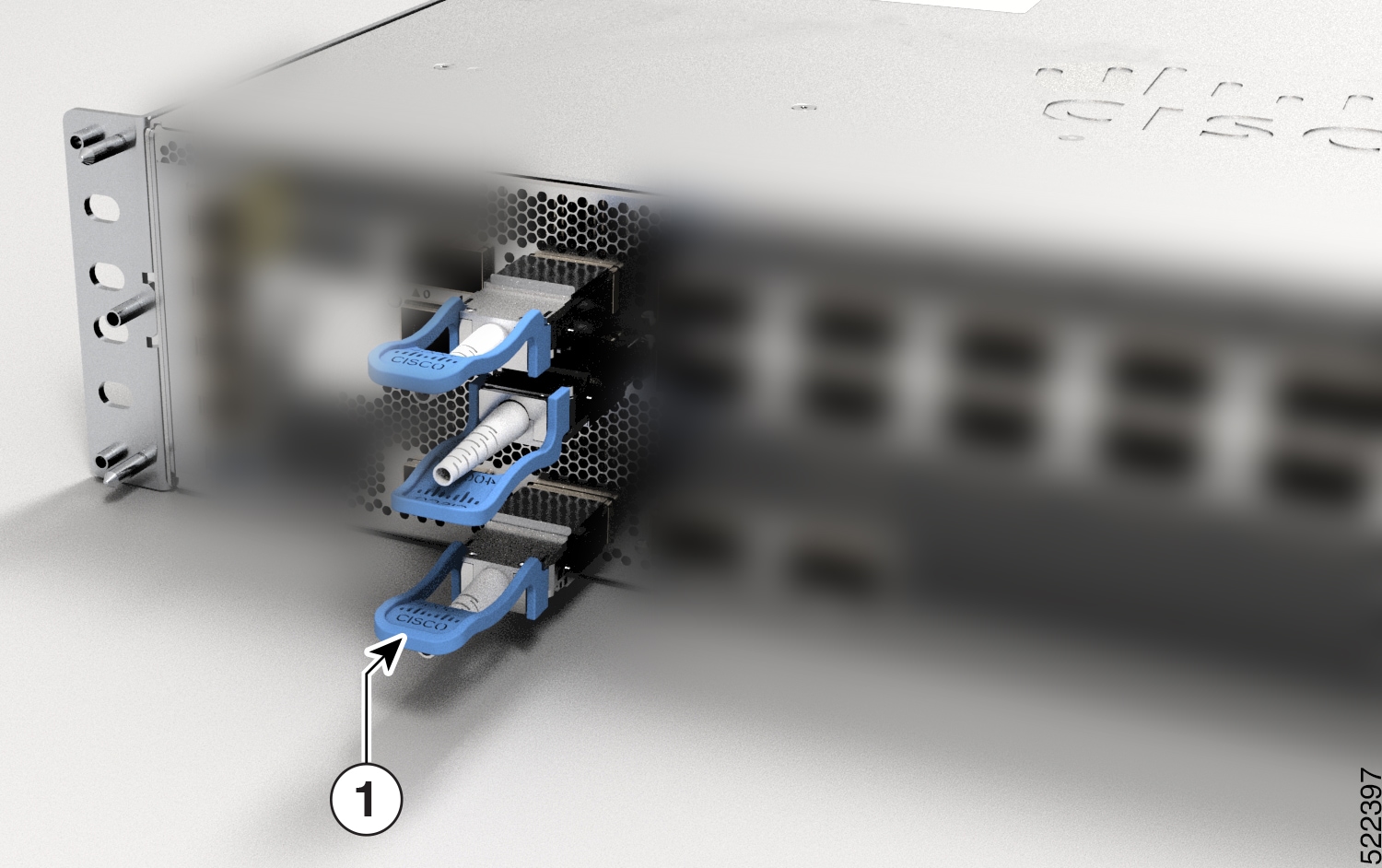
Figure 34. Removing the QSFP Transceiver Module
Figure 35. Removing the QSFP Transceiver Module from router
1
Grasp the pull-tab and gently pull to release the transceiver from the socket.
Step 4
Slide the transceiver out of the socket.
Step 5
Place the transceiver module into an antistatic bag.


 Feedback