Cisco 8400 Router Overview

The Cisco 8404-SYS-D (4RU) router is a full-featured, modular and programmable aggregation router. It is designed for the cost-effective delivery of converged mobile (IP RAN, Mobile xHaul), residential, and business services (MEF CE 3.0, layer 2/layer 3 and EVPN). The Cisco 8404-SYS-D router provides redundancy, shallow depth, low power consumption, high Ethernet interface density, and high services scale, is optimized for aggregation and remote Point-Of-Presence (POP) applications.

The Cisco 8404-SYS-D router combines the redundancy and I/O diversity of distributed systems with the economics and simple elegance of fixed platforms.

For more details on the Cisco 8404 series routers, see Cisco 8404 Router Data Sheet.

Cisco 8404-SYS-D router features

  • Fully redundant and centralized forwarding

  • Cisco Silicon One K100 ASIC with network bandwidth of 4.8Tbps.

  • Six Modular Port Adapters (MPA) that comprises:

    • Four slots of MPAs with bandwidth of 0.8 Tbps each and total bandwidth of 3.2 Tbps.

    • Two Integrated MPA with bandwidth of 0.8 Tbps each and total bandwidth of 1.6 Tbps.

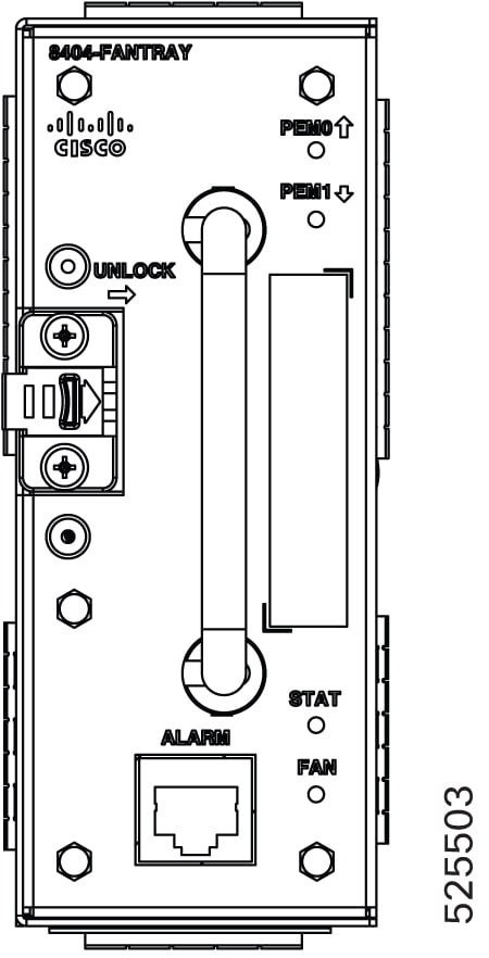
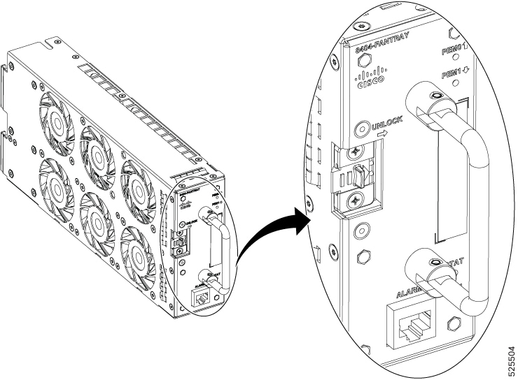
  • Single fan tray working with right to left airflow.

  • Support for 1+1 power entry modules with redundancy configurations, capable of delivering a maximum 1.8KW to the router.

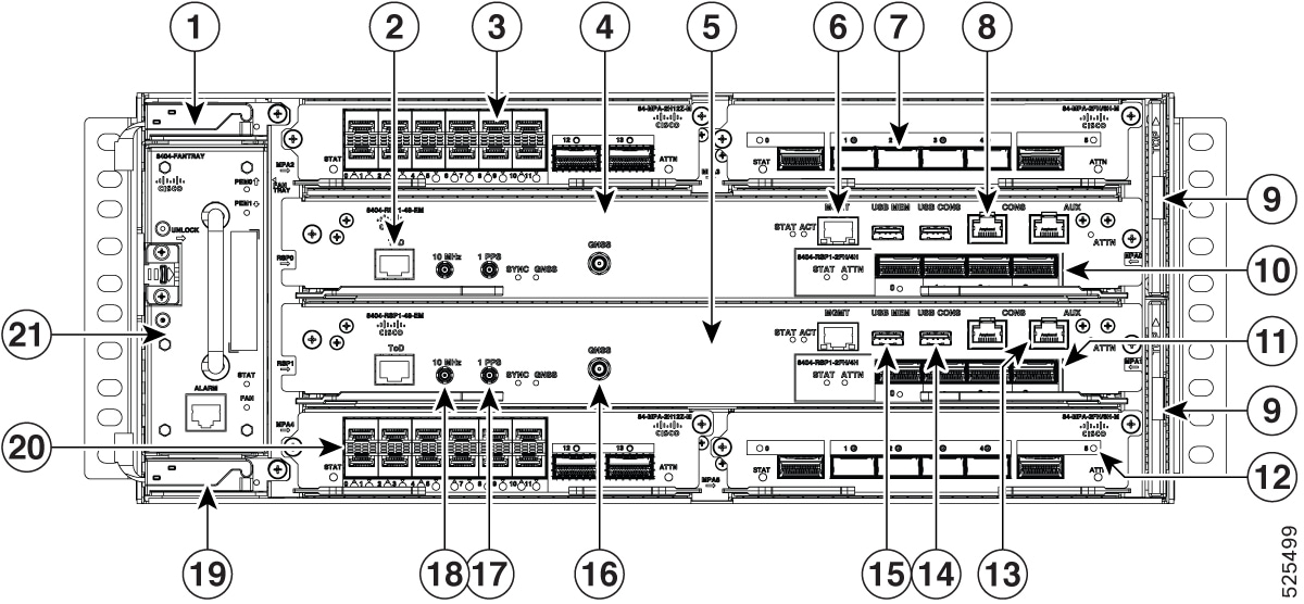
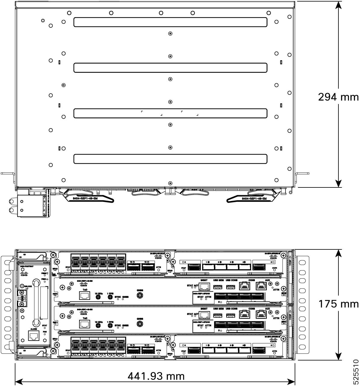
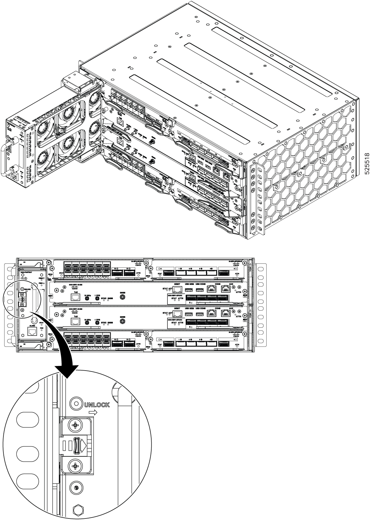
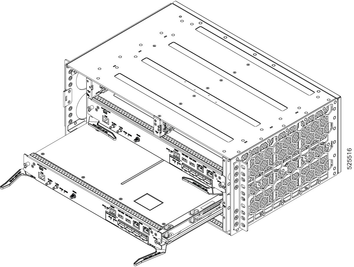
The image below illustrates the Cisco 8404-SYS-D Router chassis design.

Figure 1. Cisco 8404-SYS-D Router Front Panel

1

PEM0

2

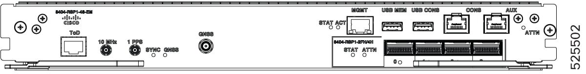
Time of the Day (ToD) port

3

Modular Port Adapter (MPA) slot 2

4

Route switch Processor (RSP) slot 0

5

RSP slot 1

6

Management (MGMT) port

7

MPA slot 3

8

Console port

9

Dust filters

10

Integrated MPA slot 0

11

Integrated MPA slot 1

12

MPA slot 5

13

Auxilary console port

14

USB console port

15

USB Memory port

16

GNSS antenna module

17

1 PPS in/out port

18

10 MHz in/out port

19

PEM1

20

MPA slot 4

21

Fan Tray

-

-

The cabling for all interfaces (power, data and control) are on the front side of the chassis. The chassis grounding point is located on the rear side of the chassis.

System Specifications

Figure 2. Cisco 8404-SYS-D Router System Specifications
Table 1. System Specifications - Abridged

Component

Specification

Cisco 8404-SYS-D Router - Physical

Height: 6.88 in. (175 mm) - 4RU

Width: 17.40 in. (442 mm)

Depth: 11.61 in. (295 mm)

Weight:

  • Fully loaded chassis approximate maximum weight: 58.86 lb (26.7 kg)

Power input (Maximum)

DC feed (-40 to -72V)

1+1 Redundancy

DC input voltage

For 1200W DC PEM, voltage range: –40.8V to –72V DC, nominal –48V/–60V DC

For the complete set of specifications, see the Cisco 8404 Router Data Sheet.

Modular Port Adapters

There are three Modular Port Adapters (MPAs) for the Cisco 8404-SYS-D router:

  • 84-MPA-2H12Z-M with 2-port 100G QSFP-28 and 12-port 1G/10G/25G/50G SFP56

  • 84-MPA-4H2FH-M with 2-port 400G or 6-port 100G QSFP-DD

  • Integrated Modular Port Adapter with 2-port 400G or 4-port 100G (4 x QSFP-DD)

84-MPA-4H2FH-M with 2-port 400G or 6-port 100 GE QSFP-DD

A modular 2-port QSFP56-DD and 4-port QSFP28 MPA capable of supporting 2 x 400G or 6 x 100G that can occupy the MPA slots from 2 to 5. This MPA provides 800 Gbps of maximum throughput with MACsec support on all ports. The MPA can be operated either in 2 x 400G native mode or a mix of 400G and 100G with each of the three adjacent ports sharing the total of 400G of capacity.

Figure 3. 2-port QSFP56-DD and 4-port QSFP28 MPA

84-MPA-2H12Z-M with 2-port 100G QSFP-28 and 12-port 1G/10G/25G/50G SFP56

A modular 12-port SFP56 and 2-port QSFP-28 MPA that can occupy the MPA slots from 2 to 5. This MPA provides 800 Gbps of maximum throughput with MACsec support on all ports. The MPA supports 12-port 1G/10G/25G/50G and 2-port 100G ports. It supports 4-port 10G or 4-port 25G breakout.

Figure 4. 12-port SFP56 and 2-port QSFP-28 MPA

Integrated Modular Port Adapter

The RSP incorporates an integrated MPA, the iMPA, with 2-port 400G or 4-port 100G ports. This is a true MPA that can also be accessed by a second installed RSP for full redundancy.

Figure 5. Cisco 8404 route switch card

Fan tray module and external alarm inputs

Fan tray module (8404-FAN-TRAY)

Fan-tray modules are vertically mounted, on the left of the chassis that pulls air through the horizontally mounted active cards. The airflow direction of the fan tray module is from right to left.

Figure 6. Fan tray module (8404-FAN-TRAY)

The fan trays are located on the left side of the chassis, while the dust filters are located on the right side of the chassis.

Figure 7. 8404-FAN-TRAY
Figure 8. Detailed view of 8404-FAN-TRAY

Fan redundancy is supported on the following conditions:

  • The router can work indefinitely on a single fan failure. And the time to replace the fan tray may depend upon the temperature levels of the critical components.

  • During two or more fan failures, the router does continue to work as long as all the critical components in the router are within the specified temperature limits.

Dust Filter

The two set of dust filters (set of two filters) are located on the right side of the chassis to prevent dust from entering the chassis.

External alarm inputs

The router supports four dry contact alarm inputs through an RJ45 jack on the fan tray.

The alarm condition is normally open, which indicates that no current flows through the alarm circuit, and the alarm is generated when the current is flowing.

Each alarm input can be provisioned as being critical, major, or minor.

RSP Modules (8404-RSP1-48-EM)

The Cisco 8404-SYS-D router has horizontally mounted single card with height of 1.74 inches.


Note


On the Cisco 8404-SYS-D platform, dual Route Switch Processors (RSPs) can be installed. However, it is recommended to use a single active RSP and disable the second RSP. Note that Route Processor Failover (RPFO) is not supported in Cisco IOS XR release 26.1.1.


When redundant RSP is installed, the control and data plane are 1+1 redundant and the standby RSP components are in hot-standby state, ready to take over as active in the event of a failover.


Note


A failover indicates a failure in the software or in the card due to reasons, such as RSP card OIR, host kernel crash or virtual machine crash triggering heartbeat failure.

Whereas, switchover is a graceful operator-initiated task that leads to the RSP being brought down.


The RSP modules handle the data plane, network timing, and control plane functionalities for the router. The RSP configuration allows you to use Cisco IOS XR software to control chassis management, redundancy, external management, and system status indications on the router.

The card has an integrated MPA which functions as a MPA card .The RSP card has four QSFP-DD ports on its front panel part of the integrated MPA.

Figure 9. View of RSP Module in the chassis

RSP features include:

  • Redundant RSP management—The RSP manages detection of RSPs, exchange of health and status information, role negotiation, function for detection, health and status exchange, role negotiation.

  • Traffic management, including buffering, queuing, and scheduling, Ethernet MAC functions.

  • Network clocking functions including phase and time-of-day for 1 PPS, 10 MHz, and 1588 PTP clock references.

  • Storage of software images, system configuration, and sysLog.

  • External management interfaces (RS232 console, management ENET, USB console, USB storage) and system status LED indicators.

  • Centralized data plane, timing, and control plane functions for the system.

  • High-level control of interface modules.

  • Management functionalities for the router.

  • The swtich card has integrated MPA with a front panel that supports configuration for either 2x400G or 4x100G optical ports. The two adjacent ports are designed to share a combined maximum bandwidth of 400 Gbps.

  • Control plane (host) CPU and associated memory in which IOS-XR and platform control software runs

Power Entry Module (8404-DC-PEM)

The Cisco 8404-SYS-D router supports two DC Power Entry Modules (PEM), PEM0 and PEM1 in 1+1 mode.

The DC power entry modules support:

  • -48V DC to 60V DC, 45A max

  • Reverse polarity protection

  • DC power oring for 1+1 redundancy

  • DC surge protection and filtering

  • Power green LED on front panel to indicate valid input DC input voltage above 36V.

The PEM front side power connector is the DC power entry to the system. The 6-AWG, 2-hole lugs are crimped to the DC PEM wires. The lugs are then screwed to the PEM connector. The router can accept unregulated negative DC supply and is powered on within the operating voltage range as specified in the DC Power Entry Module Specifications Table. As the router is designed to accept a direct DC feed, specific care needs to be taken before powering on the PEM as mentioned in the warning statement.


Warning


Before connecting the PEM module to the live supply, ensure that the supply provided is DC supply and maximum voltage does not exceed the maximum operating voltage. The PEM does not protect against continuous DC high voltage above 72 V, any wrong feed to an AC source can cause severe damage to the equipment. Cisco does not guarantee protection of equipment in such scenarios.

Ensure that the router is powered from a DC feed which has proper isolation and necessary protection mechanisms against any high voltage crossing on this feed.


Refer the table for the DC PEM specifications.

Table 2. DC Power Entry Module Specifications

Part numbers

Values

Input maximum current specification

45 A

Minimum input voltage

-40 VDC

Maximum input voltage

-72 VDC

Minimum and maximum wire gauge of the lug for DC input

8 to 6 AWG

Maximum power

1800 W


Note


We highly recommend you to use an external surge protector device for the deployments where there is a risk of higher surge than specified for these PEMs.

Redundancy

The router supports two PEMs units that can be used in 1+ 1 modes, depending on the overall power requirement of the system.

The Cisco 8404-SYS-D router supports voltage redundancy between the PEM modules. The router will draw current from the PEM with the higher input voltage.

If you install a redundant PEM on the Cisco 8404-SYS-D router, we recommend that you connect each PEM to a separate input power source in order to ensure that the router maintains power in the event of a power interruption that is caused by an electrical failure, a wiring fault, or a tripped circuit breaker.

Network timing interfaces with GNSS

The route processor supports the following network timing interfaces:

  • 1PPS input or output—Mini coaxial connectors

  • 10 MHz input or output—Mini coaxial connectors

Network timing interfaces support redundancy in a redundant RSP configuration. Network timing interfaces on a redundant RSP remain in operation while the RSP is in hot standby mode.

  • 1PPS input or output and ToD input or output—The interface is used for input or output of Time-of-Day (ToD) and 1PPS pulses. ToD format includes both NTP and IEEE 1588-2008 time formats.

  • The same RS422 pins for 1PPS and ToD are shared between the input and output directions. The direction for each can be independently configurable through software.

GNSS

The GNSS module is present on the RSP. It is an integrated module that allows direct interface with the external antenna.


Warning


To avoid safety issues, use only No. 26 AWG or larger telecommunication line cord. Statement 1023


Note


The GNSS module is not hot swappable.


GNSS Module RF Input Requirements

  • The GNSS module requires an active GPS/GNSS antenna with built-in Low-Noise Amplifier (LNA) for optimal performance. The antenna LNA amplifies the received satellite signals for two purposes:

    • Compensation of losses on the cable

    • Lifting the signal amplitude in the suitable range for the receiver frontend

    The Amplification required is 22dB gain + cable/connector loss + Splitter signal loss.

    The recommended range of LNA gain (LNA gain minus all cable and connector losses) at the connector of the receiver module is 22dB to 30dB with a minimum of 20dB and a maximum of 35dB.

  • GNSS module provides 5V to the active antenna through the same RF input.

  • Surge requirement:

    • GNSS modules have built-in ESD protections on all pins, including the RF-input pin. However, additional surge protection may be required if rooftop antennas are being connected, to meet the regulations and standards for lightning protection in the countries where the end-product is installed.

    • A lightning protection must be mounted at the place where the antenna cable enters the building. The primary lightning protection must be capable of conducting all potentially dangerous electrical energy to PE (Protective Earth).

    • Surge arrestors should support DC-pass and suitable for the GPS frequency range (1.575GHz) with low attenuation.

  • Antenna Sky visibility:


    Note


    The antenna terminal should be earthed at the building entrance in accordance with the ANSI/NFPA 70, the National Electrical Code (NEC), in particular Section 820.93, Grounding of Outer Conductive Shield of a Coaxial Cable.


  • Use a passive splitter if more than one GNSS modules are fed from a single antenna.

USB ports

A single USB 2.0 Type-A receptacle on the front panel of the router provides console access for Cisco software and diagnostics. While it uses the Type-A connector, it operates as a USB peripheral only for connection to an external host computer. This interface requires the use of a Type-A to Type-A connector instead of a standard USB cable.

USB memory port

A single USB port supports USB3.0 which is used as an external memory interface. The maximum memory limitaion is <value>.


Note


  • Use of the USB port is mutually exclusive of the RS232 console port.

  • This interface requires the use of a Type-A to Type-A USB cable.

  • If you insert the USB cable and connect to the host computer, then you can only enter the commands using the USB.


RS232 console

The RS232 console port in RJ45 form factor on the front panel of the router is for Cisco software and diagnostics access.

Table 3. RS232 console pin definition
Pin Number Signal Direction Description
1 -- -- No Connection
2 -- -- No Connection
3 TXD Output RS232 Transmit Data
4 GND Ground Ground
5 GND Ground Ground
6 RXD Input RS232 Receive Data
7 -- -- No Connection
8 -- -- No Connection

AUX port

Online Insertion and Removal

The Cisco routers, MPA, and fan tray are designed to support online insertion and removal (OIR). However, time-to-OIR for fan tray is dependent on the temperature of the chassis. At room temperature of up to 30° C, fan tray OIR should be done within two minutes.

Table 4. Ambient Teperature and Fan Tray OIR

Ambient Temperature (in Celsius)

Fan Operation

Replacement Time

Remarks

40°

Single fan failure

2 minutes

Single fan failure and all other fans running at maximum speed


Note


It is not recommended to perform fan tray OIR above the ambient temperature of 40° C.