Replace chassis components


Note


The images in this chapter are only for representation purposes, unless specified otherwise. The chassis' actual appearance and size may vary.


Remove the DC PEM

This section provides information about removing and replacing the DC PEM in the Cisco 8404-SYS-D router.


Note


The Cisco 8404-SYS-D router power supplies are hot-swappable. If you have installed redundant PEM modules, you can replace a single PEM without interrupting power to the router.

Caution


To avoid erroneous failure messages, allow at least two minutes for the system to reinitialize after a PEM has been removed or replaced.


Warning


When you install the unit, the ground connection must always be made first and disconnected last. Statement 1046


Warning


Before performing any of the following procedures, ensure that power is removed from the DC circuit. Statement 1003


Warning


Only trained and qualified personnel should be allowed to install, replace, or service this equipment. Statement 1030


Warning


Installation of the equipment must comply with local and national electrical codes. Statement 1074


Follow these steps to remove and replace the DC PEM on the Cisco 8404-SYS-D router:

Procedure


Step 1

Before servicing the PEM, switch off the circuit breaker in your equipment area. As an additional precaution, tape the circuit-breaker switch in the Off position.

Step 2

Slip on the ESD-preventive wrist strap that is included in the accessory kit.

Step 3

Switch the PEM circuit-breaker switch to the Off (O) position.

Step 4

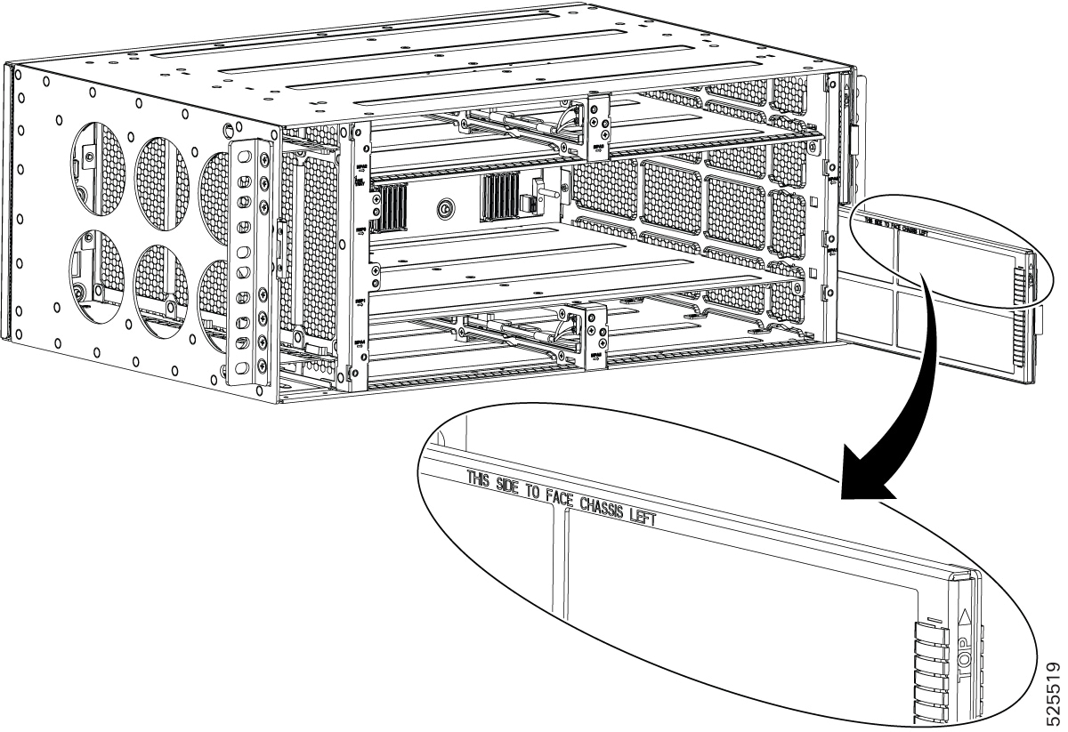
Remove the PEM out of the chassis with the captive screws unscrewed and pull out half way from the chassis.

Step 5

Open the protective cover of the PEM which is planned to remove . Using a screw nut remover, remove the two screws from the terminal connector and take the DC power LUGs with the DC power cables.

Step 6

Place the screws removed back to the terminal connector and close the protective LID.

Step 7

Pull out the PEM from the chassis fully.


Replace the DC PEM

This section provides information about removing and replacing the DC PEM in the Cisco 8404-SYS-D router.

The Cisco 8484-SYS-D router supports two DC power entry modules 8404-DC-PEM. The PEM can accept negative DC input voltage -40V to -72V and dual feed support power redundancy without disrupting power to router.


Caution


To avoid erroneous failure messages, allow at least two minutes for the system to reinitialize after a PEM has been removed or replaced.


Warning


When you install the unit, the ground connection must always be made first and disconnected last. Statement 1046


Warning


Before performing any of the following procedures, ensure that power is removed from the DC circuit. Statement 1003


Warning


Only trained and qualified personnel should be allowed to install, replace, or service this equipment. Statement 1030


Warning


Installation of the equipment must comply with local and national electrical codes. Statement 1074


Follow these steps to remove and replace the DC PEM on the Cisco 8404-SYS-D router:

Procedure


Step 1

Before servicing the PEM, switch off the circuit breaker in your equipment area. As an additional precaution, tape the circuit-breaker switch in the Off position.

Step 2

Slip on the ESD-preventive wrist strap that was included in the accessory kit.

Step 3

Loosen the captive screws on the DC PEM and pull out the PEM partially so that there is enough space to open the terminal block cover.

Step 4

Open the terminal block cover to unscrew and remove the lugs.

Step 5

Grasping the PEM handle with one hand, pull the PEM out from the chassis while supporting it with the other hand.

Step 6

Replace the DC PEM within 5 minutes.


Remove and replace the air filter

The chassis is shipped with two blank fan filter covers with the same product identifier.


Note


Air filters are consumable items and must be ordered separately by customers. Customers may contact TAC for assistance in identifying the correct air filter PID to order. We recommend having spare air filters in stock.


To install the air filter:

Before you begin

If the cables from the interface modules on the right of the chassis cross over the air filters, gently lift the cables to clear enough space to remove the air filters from the chassis.

Procedure


Step 1

Slip on the ESD-preventive wrist strap that was included in the accessory kit.

Step 2

Pull out the blank fan filter covers.

Step 3

Slide the new air filters onto the fan tray as shown in the figure below.

Figure 1. air Filter

Note


The air filter is a sungle-use component.


Remove and replace the fan tray

This section describes the removal and replacement of the fan tray module (8404-FAN-TRAY).


Note


Ensure that you keep your fingers, clothing, and jewelry away from the fans when installing or removing the fan tray module. Exposed circuitry is an energy hazard.

Caution


To avoid erroneous failure messages, allow at least two minutes for the system to reinitialize after the fan tray has been replaced.


Procedure


Step 1

Slip on the ESD-preventive wrist strap that was included in the accessory kit.

Step 2

Using a No. 2 Phillips screwdriver, loosen the captive installation screw.

Step 3

Move the latch unlock slider to the right to unlock the fan tray from the chassis. The latch is found in the left side from middle of the fan tray.

Step 4

Grasp the fan tray handle with one hand and the outside of the chassis with the other hand with the latch slider in the unlock position.

Caution


The fans are exposed on the right side of the fan tray. Keep your fingers, clothing, and jewelry away from the fans. Always handle the fan tray by the handle.

Step 5

Pull the fan tray toward you no more than 1 inch to disengage it from the power receptacle on the midplane.

Step 6

Wait at least 5 seconds to allow the fans to stop spinning. Then, pull the fan trayrout toward you and out of the router.

Note

 
As the fan tray slides out of the chassis, support the bottom of the fan tray with one hand and keep your other hand on the fan tray handle.

Note

 
The chassis must not be allowed to operate without functioning fans for more than 5 minutes.

Remove an RSP module

Before you remove an RSP from the router, you should save the current configuration on a TFTP server or an external USB flash drive, using the copy running-config {ftp | tftp | harddisk: } command. This saves you time when bringing the module back online.


Warning


Hazardous voltage or energy is present on the backplane when the system is operating. Use caution when servicing. Statement 1034


Warning


Invisible laser radiation may be emitted from disconnected fibers or connectors. Do not stare into beams or view directly with optical instruments. Statement 1051


To remove an RSP module:

Procedure


Step 1

Slip on the ESD-preventive wrist strap that was included in the accessory kit.

Step 2

Disconnect any cables attached to the ports on the module.

Step 3

Verify that the captive installation screws on all the RSP modules in the chassis are tight. This step ensures that the space created by the removed module is maintained.

Note

 
If the captive installation screws are loose, the EMI gaskets on the installed modules will push the modules toward the open slot, which in turn reduces the size of the opening and makes it difficult to remove the module.

Step 4

Loosen the two captive installation screws securing the RSP module you intend to remove from the chassis.

Step 5

Observe the status LED on the RSP module. Wait until the LED turns off—this typically takes about 5 to 8 seconds.

Step 6

To ensure the RSP is ready for removal, verify that it is in the SHUTDOWN state by entering the show platform command from the console.

Once the status LED is off or the RSP is confirmed to be in the SHUTDOWN state, then RSP can be pulled out from the slot.

Step 7

Place your thumbs on the ejector levers (see ). Simultaneously rotate both ejector levers outward to unseat the RSP module from the backplane connector.

Step 8

Observe the status LED on the RSP. If the LED remains green and the RSP is still in the Operational state, do not remove the module yet.

Step 9

Use the rsp shutdown command to transition the RSP to a safe state for removal. Wait for the status LED to turn off and verify that the RSP is no longer operational.

Step 10

Once the RSP is in the shutdown state and the LED is off, you may safely pull the RSP out of its slot.

Caution


To prevent ESD damage, handle modules by the carrier edges only. Do not hold the RSP with the ejector levers as weight of the RSP card might bend the lever.

Step 11

Place the module on an antistatic mat or antistatic foam, or immediately reinstall the module in another slot.

Step 12

Install blank module filler plates (Cisco part number: 8404-RSP-BLANK) in empty slots, if any.

Warning


Blank faceplates and cover panels serve three important functions: they prevent exposure to hazardous voltages and currents inside the chassis; they contain electromagnetic interference (EMI) that might disrupt other equipment; and they direct the flow of cooling air through the chassis. Do not operate the system unless all cards, faceplates, front covers, and rear covers are in place. Statement 1029


Remove MPA

To remove an MPA module:

Procedure


Step 1

Slip on the ESD-preventive wrist strap available in the accessory kit.

Step 2

Remove optics and cables from the front panel.

Step 3

Loosen the two captive installation screws on the MPA module you plan to remove from the chassis.

Step 4

Wait for the status LED to turn off; this process typically takes about 5 to 8 seconds. You can also verify that the MPA has entered the SHUTDOWN state by checking the console log or issuing the show platform command.

Step 5

Once the status LED turns off or the MPA is confirmed to be in the SHUTDOWN state, it is safe to remove the MPA from the slot. Position your thumbs on the ejector levers (refer to the illustration) and, at the same time, rotate both ejector levers outward to disengage the module from the backplane connector.

Step 6

If the status LED remains green and the MPA is still in the Operational state, issue the MPA shutdown command before attempting to remove the MPA from its slot.

Step 7

Firmly grasp the front edge of the module and carefully slide it straight out of the slot. For chassis with horizontal slots, support the module from underneath with one hand as you remove it to prevent it from dropping. Avoid touching any circuitry on the module to prevent damage from static electricity or physical contact.

Step 8

Place the module on an antistatic mat or antistatic foam or immediately reinstall the module in another slot.

Step 9

Install blank module filler plates (84-MPA-BLANK and 84-RSP-BLANK) in any empty slots to maintain proper airflow and ensure system integrity.

Warning


Blank faceplates and cover panels serve three important functions: they prevent exposure to hazardous voltages and currents inside the chassis; they contain electromagnetic interference (EMI) that might disrupt other equipment; and they direct the flow of cooling air through the chassis. Do not operate the system unless all cards, faceplates, front covers, and rear covers are in place. Statement 1029 (edited)


Hot-swap an RSP or MPA

The Cisco 8404-SYS-D router provides a feature that allows you to remove and replace a redundant RSP module without powering down the router. This feature, called hot-swapping or OIR, allows you to remove and replace a redundant module without disrupting router operation.


Note


Before replacing the card, you must perform a graceful shutdown of the card to avoid disk corruption

When two redundant modules are installed in the router, only one of the modules is active. The other one runs in standby mode, ready to take over processing if the active module fails.

The RSP planned to remove to be gracefully shutdown so the other RSP will be in active mode

Use the following guidelines when performing an OIR on an MPA:

  • Allow at least two minutes for the system to reinitialize before inserting a new MPA.

  • Avoid inserting a new MPA during bootup until the active and standby RSPs have reached an OK state.

  • When inserting multiple MPAs into the chassis, wait until each MPA reaches an OK state before inserting the next MPA.