Cisco 8100 Series Switches
The Cisco 8100 Series Switches utilizes Cisco’s new System-on-Chip (SoC) model to deliver full routing functionality with a single ASIC per Switch. The SoC architecture delivers enhanced programmability, greater packet-processing flexibility, and support for large forwarding tables.
The Cisco 8100 series Switches include the following variants:
-
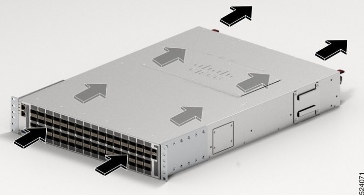
Cisco 8102-64H-O - It provides 6.4 Tbps of network bandwidth with dramatically lower power consumption than contemporary 10 Tbps systems. The Cisco 8102-64H-O Switch is a fixed port, high density, two rack unit form-factor Switch. There are 64 QSFP28 ports on the Switch, each supporting 100GbE. The Cisco 8102-64H-O supports Cisco-qualified open-source network operating systems, such as SONiC (Software for Open Networking in the Cloud).
-
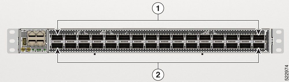
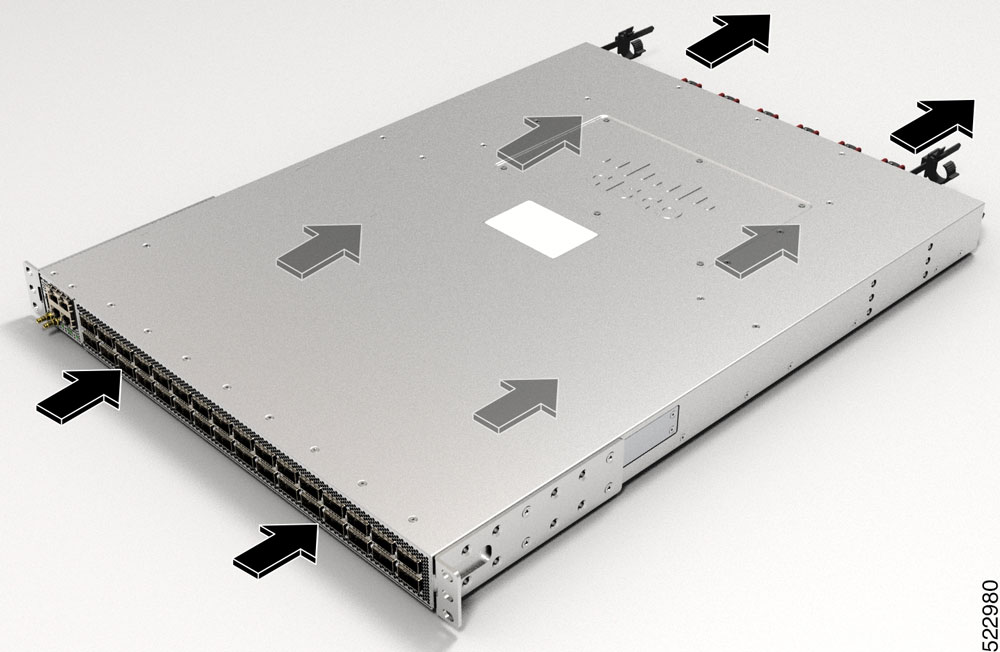
Cisco 8101-32FH-O - It provides 12.8Tbps of network bandwidth. The Cisco 8101-32FH-O Switch is a fixed port, high density, one rack unit form-factor Switch. There are 32 QSFP-DD ports on the Switch, each supporting 400GbE. The Cisco 8101-32FH-O supports Cisco-qualified open-source network operating systems, such as SONiC (Software for Open Networking in the Cloud). The functionality and installation of this Switch is similar to that of Cisco 8201-32FH. The Hardware Installation Guide for Cisco 8201-32FH is available here.
-
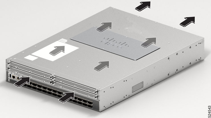
Cisco 8101-32H-O - It provides 3.2 Tbps of network bandwidth with dramatically lower power consumption than contemporary 10 Tbps systems. The Cisco 8101-32H-O Switch is a fixed port, high density, one rack unit form-factor Switch. There are 64 QSFP28 ports on the Switch, each supporting 100GbE. This variant supports the Cisco-qualified open-source network operating system, such as SONiC (Software for Open Networking in the Cloud).
-
Cisco 8111-32EH-O - It provides 25.6Tbps of network bandwidth. The Cisco 8111-32EH-O Switch is a fixed port, high density, one rack unit form-factor Switch. There are 32 QSFP-DD ports on the Switch, each supporting 800GbE. This variant supports the Cisco-qualified open-source network operating system, such as SONiC (Software for Open Networking in the Cloud).
-
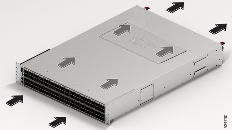
Cisco 8122-64EH-O - It provides 51.2 Tbps of network bandwidth. The Cisco 8122-64EH-O Switch is a fixed port, high density, two rack unit form-factor Switch. There are 64 QSFP-DD ports on the Switch, each supporting 800GbE. This variant supports the Cisco-qualified open-source network operating system, such as SONiC (Software for Open Networking in the Cloud).
-
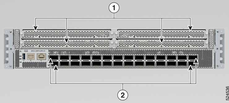
Cisco 8102-28FH-DPU-O - This is a first-generation smart switch equipped with the Cisco Silicon One Q200L switching processor and an AMD DSC-200 Data Processing Unit (DPU), all housed in a two-rack unit form factor. It offers a total network bandwidth of 12.8Tbps, which includes 11.2Tbps for switching and 1.6Tbps for DPU processing, and it contains 28 QSFP-DD 400 GbE ports.
The Cisco 8102-28FH-DPU-O supports Cisco-qualified open-source network operating systems, such as SONiC (Software for Open Networking in the Cloud).
-
Cisco 8122-64EHF-O - It provides 51.2 Tbps of network bandwidth operating on the Cisco G200 network processor. The Cisco 8122-64EHF Switch is a fixed port, high density, two rack unit form-factor Switch specifically designed for hyperscale data centers. There are 64 OSFP800 ports on the Switch, each supporting 800GbE. This variant supports Cisco-qualified open-source network operating systems, such as SONiC (Software for Open Networking in the Cloud).
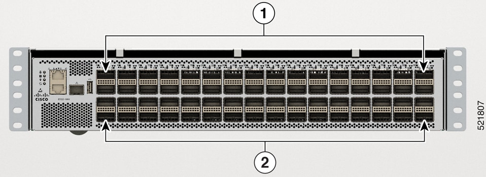
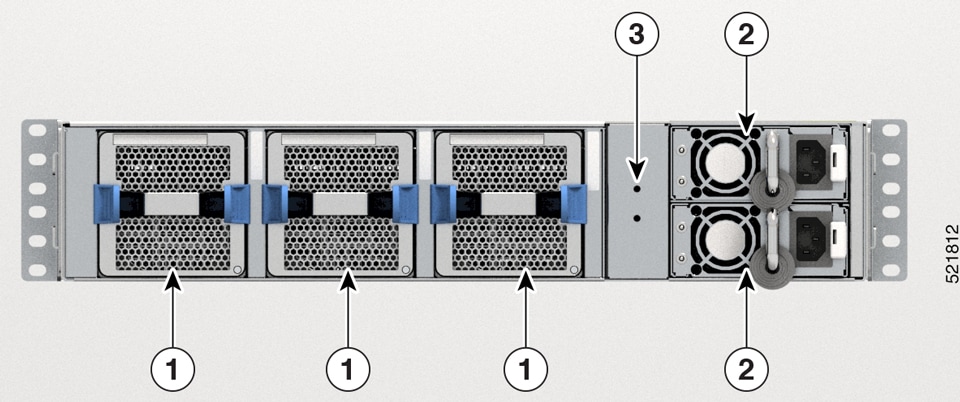
Cisco 8102-64H-O Switch Front and Rear Panel View
|
1 |
32 QSFP-DD ports |
|
2 |
32 QSPF-DD ports |
|
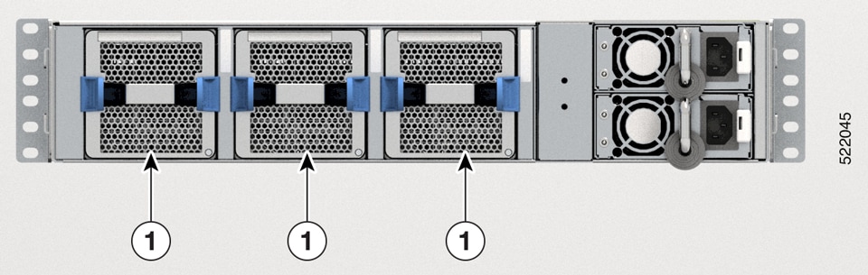
1 |
Fan Tray Three Fans: FT0, FT1, and FT2 |
|
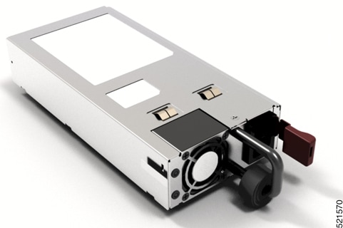
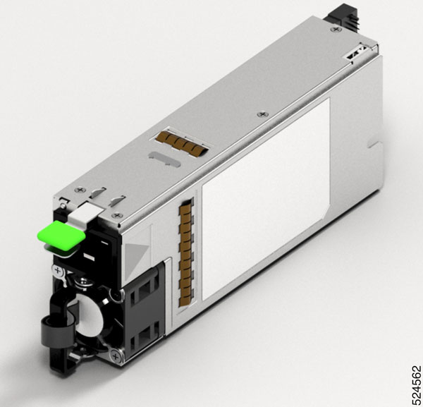
2 |
PSU-0 and PSU-1 |
|
3 |
Ground Lug Location |
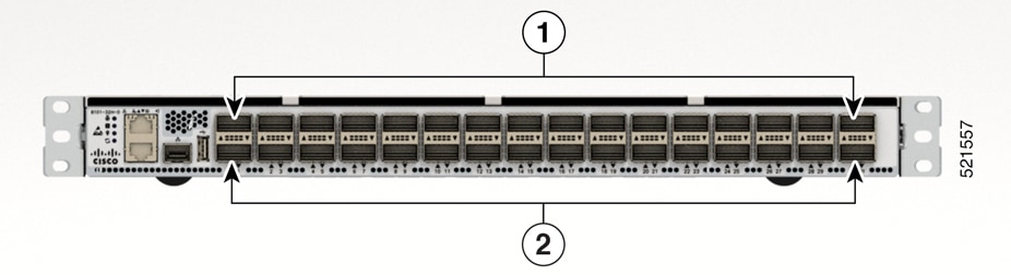
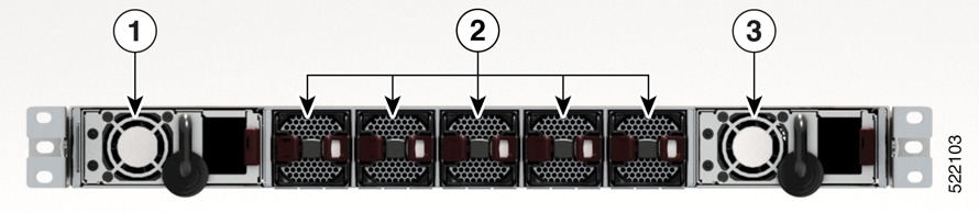
Cisco 8101-32H-O Switch Front and Rear Panel View
|
1 |
16 QSFP28 ports |
|
2 |
16 QSPF28 ports |
|
1 |
PSU-0 |
|
2 |
Fan Tray Five Fans: FT0, FT1, FT2, FT3, and FT4 |
|
3 |
PSU-1 |
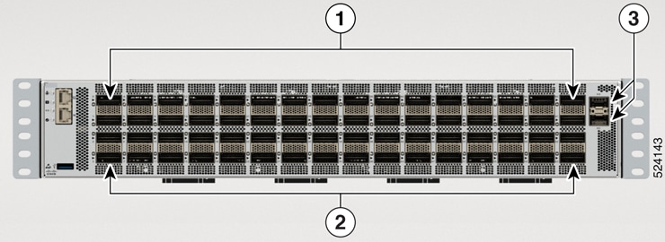
Cisco 8111-32EH-O Switch Front and Rear Panel View
|
1 |
16 QSFP-DD ports. Supports 30W optics. |
|
2 |
16 QSFP-DD ports. Supports 17W optics. |

|
1 |
PSU-0 |
|
2 |
Fan Tray Six Fans: FT0, FT1, FT2, FT3, FT4, and FT5 |
|
3 |
PSU-1 |
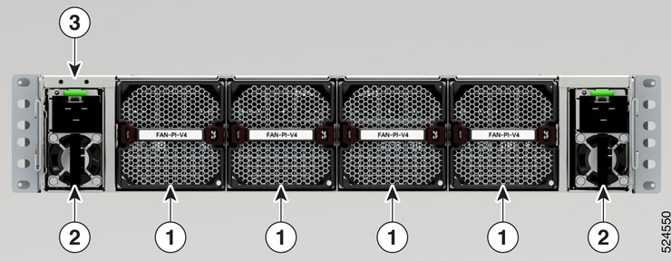
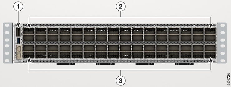
Cisco 8122-64EH-O Switch Front and Rear Panel View
|
1 |
32 QSFP-DD ports |
|
2 |
32 QSPF-DD ports |
|
3 |
2 SFP28 ports |
|
1 |
Fan Tray Four Fans: FT0, FT1, FT2, and FT3 |
|
2 |
PSU-0 and PSU-1 |
|
3 |
Ground Lug Location |
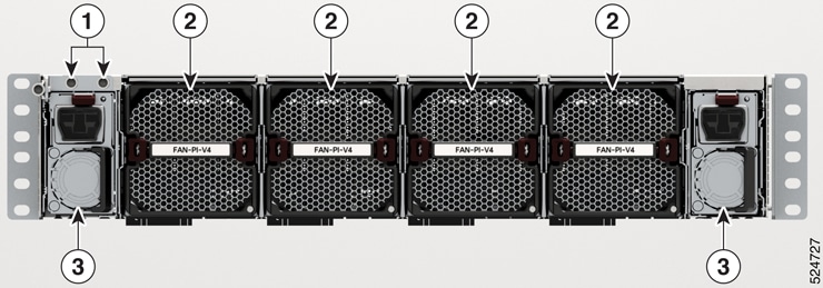
Cisco 8102-28FH-DPU-O Smart Switch Front and Rear Panel View
|
1 |
4 DPU adapters. 2 DPU complexes per adapter. |
|
2 |
28 QSFP-DD 400 GbE |
|
1 |
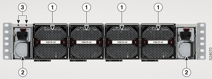
Fan Modules Four Fans: FT0, FT1, FT2 and FT3 |
|
2 |
PSU-0 and PSU-1 |
|
3 |
Ground Lug Location |
Cisco 8122-64EHF-O Switch Front and Rear Panel View
|
1 |
QSFP28 port |
|
2 |
32 OSFP800 ports |
|
3 |
32 OSFP800 ports |
|
1 |
Ground Lug Location |
|
2 |
Fan Tray Four Fans: FT0, FT1, FT2, and FT3 |
|
3 |
PSU-0 and PSU-1 |
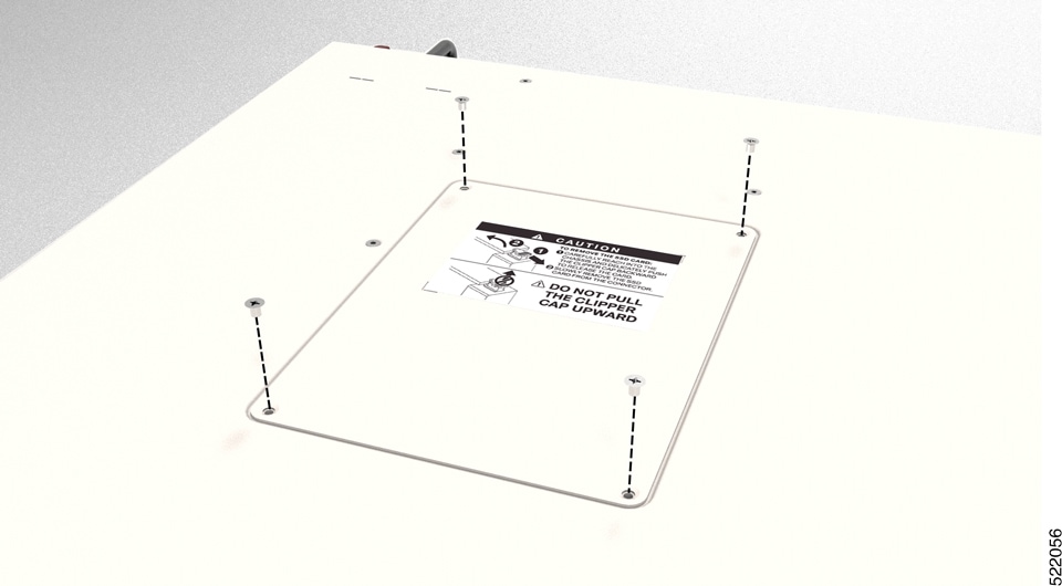
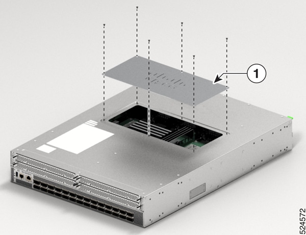
Cisco 8102-28FH-DPU-O Smart Switch DPU Adapter
The Cisco 8102-28FH-DPU-O Smart Switch features four Data Processing Unit (DPU) adapters, which are responsible for managing data plane services. Each adapter contains two DPU complexes, resulting in a total of eight DPU complexes in the switch, providing a combined data processing bandwidth of 1.6Tbps. Each DPU complex comprises of AMD DPU chip, 32GB of on board DDR4 memory, 64GB of eMMC storage and a common power management CPLD (complex programmable logic device). Each DPU adapter offers 200Gbps of network bandwidth and supports a variety of network functionalities within the smart switch.
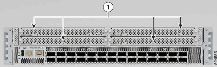
| 1 |
4 DPU adapters. 2 DPU complexes per DPU adapter. |

 Feedback