Connect Router to the Network

Port Connection Guidelines

Depending on the chassis , you can use optical modules and RJ-45 connectors to connect the ports to other network devices.

To prevent damage to the fiber-optic cables, we recommend that you keep the transceivers disconnected from their fiber-optic cables when installing the transceiver in the line card. Before removing a transceiver from the router, remove the cable from the transceiver.

To maximize the effectiveness and life of your transceivers and optical cables, ensure the following:

  • Wear an ESD-preventative wrist strap that is connected to an earth ground whenever you handle transceivers.

  • Do not remove and insert a transceiver more often than is necessary. Repeated removals and insertions can shorten its useful life.

  • Keep the transceivers and fiber-optic cables clean and dust free to maintain high signal accuracy and to prevent damage to the connectors. Attenuation (loss of light) is increased by contamination. Connector loss should be kept below 0.35 dB.

    • Clean these parts before installation to prevent dust from scratching the fiber-optic cable ends.

    • Clean the connectors regularly; the required frequency of cleaning depends upon the environment. In addition, clean connectors when they are exposed to dust or accidentally touched. Both wet and dry cleaning techniques can be effective; refer to your site's fiber-optic connection cleaning procedures.

    • Do not touch the ends of connectors. Touching the ends can leave fingerprints and cause other contamination.

  • Inspect routinely for dust and damage. If you suspect damage, clean and then inspect fiber ends under a microscope to determine if damage has occurred.
Interfaces and Port Description

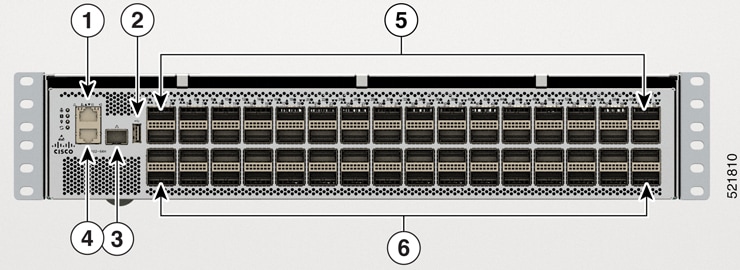
This topic explains and illustrates the interfaces and ports available on the front side of the router.

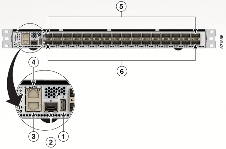
Figure 1. Cisco 8102-64H-O Router

1

10GBASE-T Control Plane Expansion Port

4

Console Port

2

USB Port Type-A

5

32 QSFP-DD ports

3

10G Management Port

6

32 QSFP-DD ports

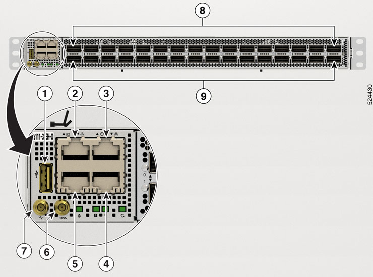
Figure 2. Cisco 8101-32FH-O Router

1

USB Port Type-A

6

Mini coax connector for 10MHz, input, and output

2

Console port

7

Mini coax connector for 1 PPS, input, and output.

3

RJ-45 connector for Time-of-Day (TOD) interface, input, and output

8

16 QSFP56-DD 400 GbE ports

4

1000BASE-T Management and BMC (Baseboard Management Controller) Port

9

16 QSFP56-DD 400 GbE ports

5

10GBASE-T Control Plane Expansion Port

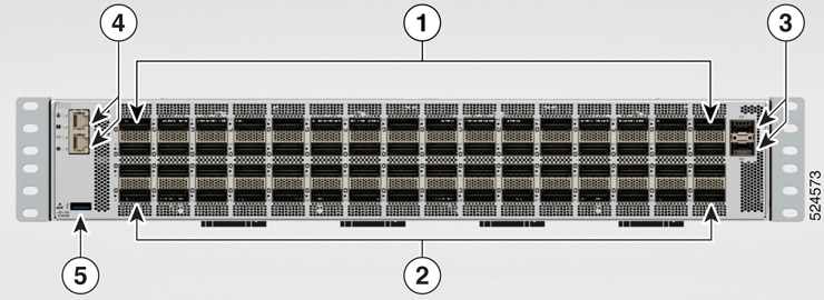
Figure 3. Cisco 8101-32H-O Router

1

USB Port Type-A

4

10GBASE-T Control Plane Expansion Port

2

Control Plane Expansion SFP/SFP+ port

5

16 QSFP28 ports

3

Console Port

6

16 QSFP28 ports

Figure 4. Cisco 8111-32EH-O Router

1

USB Port Type-A

5

10GBASE-T Control Plane Expansion Port

2

Console port

6

Mini coax connector for 10MHz, input, and output.

3

RJ-45 connector for Time-of-Day (TOD) interface, input, and output

7

Mini coax connector for 1 PPS, input, and output.

4

1000BASE-T Management and BMC (Baseboard Management Controller) Port

8

16 QSFP-DD ports. Supports 30W optics.

9

16 QSFP-DD ports. Supports 17W optics.

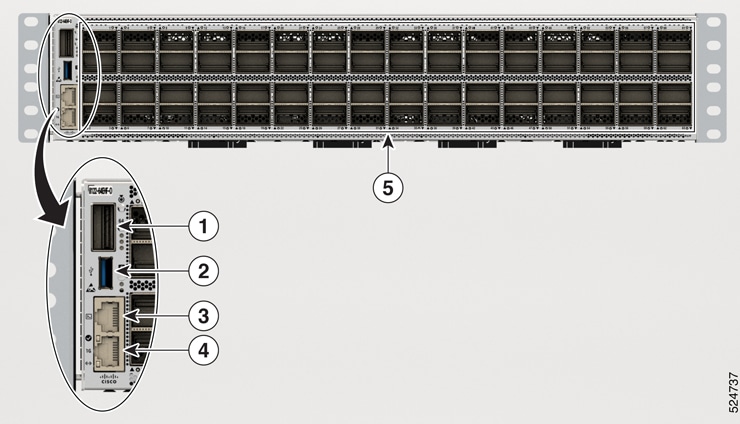
Figure 5. Cisco 8122-64EH-O Router

1

QSFP-DD ports

4

Console port and 10GBASE-T Control Plane Expansion Port

2

QSFP-DD ports

5

USB Port Type-A

3

SFP28 ports

Figure 6. Cisco 8102-28FH-DPU-O

1

DPU adapters

4

1000BASE-T Management and BMC (Baseboard Management Controller) port

2

28 QSFP-DD 400 GbE ports

5

Console port

3

USB port Type-A

Figure 7. Cisco 8122-64EHF-O Router

1

QSFP28 port

4

1000BASE-T Management and BMC (Baseboard Management Controller) port

2

USB 3.0 Port Type-A

5

64 OSFP800 ports

3

Console port

Transceiver and Cable Specifications

To determine which transceivers and cables are supported by this router, refer to the Transceiver Module Group (TMG) Compatibility Matrix Tool:

https://tmgmatrix.cisco.com

Connecting a Console to the Router

Before you create a network management connection for the router or connect the router to the network, you must create a local management connection through a console terminal and configure an IP address for the router. The router can be accessed using remote management protocols, such as SSH and Telnet. By default, SSH is included in the software image. But telnet is not part of the software image. You must manually install the telnet optional package to use it.

You also can use the console to perform the following functions, each of which can be performed through the management interface after you make that connection:

  • configure the router using the command-line interface (CLI)

  • monitor network statistics and errors

  • configure Simple Network Management Protocol (SNMP) agent parameters

  • initiate software download updates via console

You make this local management connection between the asynchronous serial port on a console device capable of asynchronous transmission. Typically, you can use a computer terminal as the console device.


Note


Before you can connect the console port to a computer terminal, make sure that the computer terminal supports VT100 terminal emulation. The terminal emulation software makes communication between the router and computer possible during setup and configuration.

Before you begin

  • The router must be fully installed in its rack. The router must be connected to a power source and grounded.

  • The necessary cabling for the console, management, and network connections must be available.

    • An RJ45 rollover cable and a DB9F/RJ45 adapter.

    • Network cabling should already be routed to the location of the installed router.

Procedure


Step 1

Configure the console device to match the following default port characteristics:

  • 9600 baud

  • 8 data bits

  • 1 stop bit

  • No parity

Step 2

Connect and RJ45 rollover cable to a terminal, PC terminal emulator, or terminal server.

The RJ45 rollover cable is not part of the accessory kit.

Step 3

Route the RJ45 rollover cable as appropriate and connect the cable to the console port on the chassis.

If the console or modem cannot use an RJ45 connection, use the DB9F/RJ45F PC terminal adapter. Alternatively, you can use an RJ45/DSUB F/F or RJ45/DSUB R/P adapter, but you must provide those adapters.


What to do next

You are ready to create the initial router configuration.

Create the Initial Router Configuration

Assign an IP address to the router management interface to connect the router to the network.

When you initially power up the router, it boots up and displays a series of configuration-related questions. You can use the default choices for each configuration except for the IP address, which you must provide.


Note


These routers are designed to boot up in less than 30 mins, provided the neighboring devices are in full-operational state.


When the system is powered on and the console port is connected to the terminal, the RP CPU messages are seen. You can toggle between BMC CPU messages and RP CPU messages by pressing the hot-key sequence Ctrl-O.

To configure IP address for Ethernet port on BMC and other additional information that is related to BMC, please see the System Setup Guide for Cisco 8000 Series Routers.

Before you begin

  • A console device must be connected with the router.

  • The router must be connected to a power source.

  • Determine the IP address and netmask that is needed for the Management interfaces: MgmtEth0/RP0/CPU0/0.

Procedure


Step 1

Power up the router.

The LEDs on each power supply light up (green) when the power supply units are sending power to the router, and the software asks you to specify a password to use with the router.

Step 2

When the system boots up for the first time, the system prompts you to create a new username and password. The following prompt appears:


!!!!!!!!!!!!!!!!!!!! NO root-system username is configured. Need to configure root-system username. !!!!!!!!!!!!!!!!!!!!

--- Administrative User Dialog ---


Enter root-system username:
% Entry must not be null.

Enter root-system username: cisco
Enter secret:
Use the 'configure' command to modify this configuration.
User Access Verification

Username: cisco
Password:


RP/0/RP0/CPU0:ios#

Step 3

Enter a new password to use for this router.

The software checks the security strength of your password and rejects your password if the system does not consider it as a strong password. To increase the security strength of your password, make sure that it adheres to the following guidelines:

  • At least eight characters

  • Minimizes or avoids the use of consecutive characters (such as "abcd")

  • Minimizes or avoids repeating characters (such as "AAA")

  • Does not contain recognizable words in the dictionary

  • Does not contain proper names

  • Contains both uppercase and lowercase characters

  • Contains numbers and letters

Note

 
Cleartext passwords cannot include the dollar sign ($) special character.

Tip

 
If a password is trivial (such as a short, easy-to-decipher password), the software rejects that password. Passwords are case-sensitive.

When you enter a strong password, the software asks you to confirm the password.

Step 4

Reenter the password.

When you enter the same password, the software accepts the password.

Step 5

Enter the configuration mode.

Step 6

Enter the IP address for the management interface.

Step 7

Enter a network mask for the management interface.

Step 8

The software asks whether you want to edit the configuration.

  • no - select this option if you don't want to edit your configuration.
  • yes - select this option if you want to edit your configuration.

    Note


    We recommend that you configure the system location altitude for fan control. This configuration allows you to specify the chassis altitude, so the router can adjust the fan speed to compensate for lower cooling capability at higher altitudes. For more details, see the environment altitude command.


Connect the Management Interface

The management port (MGMT ETH) provides out-of-band management, which lets you to use the command-line interface (CLI) to manage the router by its IP address. This port uses a 10/100/1000 Ethernet connection with an RJ-45 interface.


Caution


To prevent an IP address conflict, do not connect the MGMT 100/1000 Ethernet port until the initial configuration is complete.

Before you begin

You must have completed the initial router configuration.

Procedure


Step 1

Connect a modular, RJ-45, UTP cable to the MGMT ETH port.

Step 2

Route the cable through the central slot in the cable management system.

Step 3

Connect the other end of the cable to a 100/1000 Ethernet port on a network device.


What to do next

You are ready to connect the interface ports to the network.

Install and Remove QSFP Transceiver Modules

This section provides the installation, cabling, and removal instructions for the Quad Small Form-Factor Pluggable transceiver modules. Refer to the Cisco Optical Transceiver Handling Guide for additional details on optical transceivers.


Caution


When inserting optical transceiver modules into host ports, handle them carefully. Ensure that the applied force does not exceed 20 lbs (9.1kg).


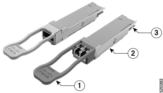
The following figure shows a 400-Gigabit QSFP-DD optical transceiver.

Figure 8. 400-Gigabit QSFP-DD Transceiver Module

1

Pull-tab

2

QSFP-DD transceiver body

3

Electrical connection to the module circuitry

Required Tools and Equipment

You need these tools to install the transceiver modules:

  • Wrist strap or other personal grounding device to prevent ESD occurrences.

  • Antistatic mat or antistatic foam to set the transceiver on.

  • Fiber-optic end-face cleaning tools and inspection equipment.

Installing the Transceiver Module


Warning


Statement 1079—Hot Surface

This icon is a hot surface warning. To avoid personal injury, do not touch without proper protection.


Caution


The transceiver module is a static-sensitive device. Always use an ESD wrist strap or similar individual grounding device when handling transceiver modules or coming into contact with system modules.

Caution


Protect the transceiver ports by inserting clean dust caps (8000-QSFP-DCAP) into any ports not in use and do not have optical modules plugged in. If optical modules are plugged in but not in use, the dust caps that were supplied with the optical modules, should be used to protect the TX and RX surfaces of the optical module.

Be sure to clean the optic surfaces of the fiber cables before you plug them back into the optical ports of another module.

The router ships with dust caps plugged in. We highly recommend you to keep the dust caps plugged in until you are ready to plug an optic.

The dust caps protect the ports from possible EMI interference and also avoid contamination due to dust collection.


Caution


To meet the EMI interference requirements, you must use the metal dust caps when the ports are not in use by optical modules.


The following table provides the supported port details and operating temperature of the QDD-400G-ZR-S and QDD-400G-ZRP-S optical modules when port side exhaust or port side intake fans and power supplies are used.

Table 1. Supported Ports and Operating Temperature of QDD-400G-ZR-S and QDD-400G-ZRP-S Optical Modules
Fixed-Port Routers Port Side Intake Fans and Power Supplies Port Side Exhaust Fans and Power Supplies Port Side Intake Operating Temperature

8101-32FH

  • QDD-400G-ZR-S – supported on all 400G ports

  • QDD-400G-ZRP-S – supported on even-numbered 400G ports

  • QDD-400G-ZR-S – not supported

  • QDD-400G-ZRP-S – not supported

40° C at sea level or 35° C at 1500 meter

8111-32EH-O

  • QDD-400G-ZR-S – supported on all 400G ports

  • QDD-400G-ZRP-S – supported on even-numbered 400G ports

Not Applicable

40° C at sea level or 35° C at 1500 meter


Note


  • The Cisco 8101-32FH fixed-port router must be operated only with 2kW power supplies while using the QDD-400G-ZR-S and QDD-400G-ZRP-S optical modules. These optical modules are not supported when 1.4KW power supplies are used.

  • The Cisco 8111-32EH-O fixed-port router must be operated only with 3kW power supplies while using the QDD-400G-ZR-S and QDD-400G-ZRP-S optical modules. These optical modules are not supported when 2KW power supplies are used.


The QSFP transceiver module has a pull-tab latch. To install a transceiver module, follow these steps:

Procedure


Step 1

Attach an ESD wrist strap to yourself and a properly grounded point on the chassis or the rack.

Step 2

Remove the transceiver module from its protective packaging.

Step 3

Check the label on the transceiver module body to verify that you have the correct model for your network. Do not remove the dust plug until you’re ready to attach the network interface cable. Dust plug is not shown in the images.

Step 4

Hold the transceiver by the pull-tab so that the identifier label is on the top.

Step 5

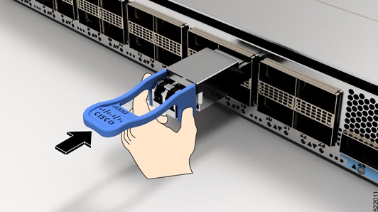
Align the transceiver module in front of the module’s transceiver socket opening and carefully slide the transceiver into the socket until the transceiver contact with the socket electrical connector.

Figure 9. Installing the QSFP Transceiver Module

Step 6

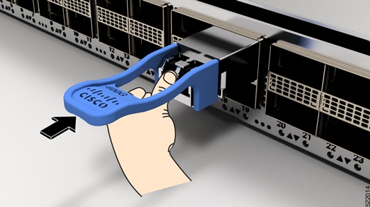
Press firmly on the front of the transceiver module with your thumb to fully seat the transceiver in the module’s transceiver socket (see the below figure).

Caution

 
If the latch isn’t fully engaged, you might accidentally disconnect the transceiver module.
Figure 10. Seating the QSFP Transceiver Module

Attach the Optical Network Cable

Before you begin

Before you remove the dust plugs and make any optical connections, follow these guidelines:

  • Keep the protective dust plugs installed in the unplugged fiber-optic cable connectors and in the transceiver optical bores until you are ready to make a connection.

  • Inspect and clean the optical connector end faces just before you make any connections.

  • Grasp the optical connector only by the housing to plug or unplug a fiber-optic cable.


Note


The transceiver modules and fiber connectors are keyed to prevent incorrect insertion.

Note


The multiple-fiber push-on (MPO) connectors on the optical transceivers support network interface cables with either physical contact (PC) or ultra-physical contact (UPC) flat polished face types. The MPO connectors on the optical transceivers do not support network interface cables with an angle-polished contact (APC) face type.

Note


Inspect the MPO connector for the correct cable type, cleanliness, and any damage. For complete information on inspecting and cleaning fiber-optic connections, see the Inspection and Cleaning Procedures for Fiber-Optic Connections document.


Procedure


Step 1

Remove the dust plugs from the optical network interface cable MPO connectors and from the transceiver module optical bores. Save the dust plugs for future use.

Step 2

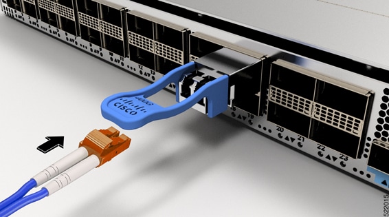
Attach the network interface cable MPO connectors immediately to the transceiver module.

Figure 11. Cabling a Transceiver Module

Removing the Transceiver Module


Caution


The transceiver module is a static-sensitive device. Always use an ESD wrist strap or similar individual grounding device when handling transceiver modules or coming into contact with modules.

To remove a transceiver module, follow these steps:

Procedure


Step 1

Disconnect the network interface cable from the transceiver connector.

Step 2

Install the dust plug immediately into the transceiver’s optical bore.

Step 3

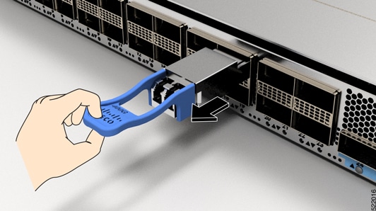
Grasp the pull-tab and gently pull to release the transceiver from the socket.

Figure 12. Removing the QSFP Transceiver Module

Step 4

Slide the transceiver out of the socket.

Step 5

Place the transceiver module into an antistatic bag.


Connect Interface Ports

You can connect optical interface ports with other devices for network connectivity.

Connect a Fiber-Optic Port to the Network

40G, 100G, 400G, and 800G transceivers are supported on Cisco 8100 series routers. Some transceivers work with fiber-optic cables that you attach to the transceivers and other transceivers work with pre-attached copper cables. You must install a transceiver in the port before installing the fiber-optic cable in the transceiver.


Caution


Removing and installing a transceiver can shorten its useful life. Do not remove and insert transceivers any more than is absolutely necessary. We recommend that you disconnect cables before installing or removing transceivers to prevent damage to the cable or transceiver.


Disconnect Optical Ports from the Network

When you need to remove fiber-optic transceivers, you must first remove the fiber-optic cables from the transceiver before you remove the transceiver from the port.

Verify Chassis Installation

After installing the chassis, use the following show commands to verify the installation and configuration in the EXEC mode. Any issue if detected, take corrective action before making further configurations.

Command

Description

show platform

Displays the state information of each card.

show inventory

Displays information about the field replaceable units (FRUs), including product IDs, serial numbers, and version IDs.

show environment

Displays all the environment-related router information.

show environment temperature

Displays temperature readings for card temperature sensors. Each Route Processor, line card, and fabric cards have temperature sensors with two thresholds:

  • Minor temperature threshold – When a minor threshold is exceeded, minor alarm occurs and the following actions occur for all four sensors:

    • Displays system messages

    • Sends SNMP notifications (if configured)

    • Log environmental alarm event that can be reviewed by running the show alarm command.

  • Major temperature threshold – When a major threshold is exceeded, a major alarm occurs and the following actions occur:

    • For sensors 1, 3, and 4 (outlet and on board sensors), the following actions occur:

      • Displays system messages.

      • Sends SNMP notifications (if configured).

      • Logs environmental alarm event that can be reviewed by running the show alarm command.

    • For sensor 2 (intake sensor), the following actions occur:

      • If the threshold is exceeded in a switching card, only that card is shut down.

      • If the threshold exceeds an active Route Processor card with HA-standby or standby present, only that Route Processor card is shut down and the standby Route Processor card takes over.

      • If you do not have a standby Route Processor card in your router, you have up to 2 minutes to decrease the temperature. During this interval, the software monitors the temperature every 5 seconds and continuously sends system messages as configured.

Note

 
  • Cisco recommends that you install dual Route Processor cards.

  • For some card temperature sensors, the temperature thresholds for both minor and major might display 'NA'. This is an expected behaviour and indicates that there are no alarms for those corresponding thresholds.

show environment power

Displays the power usage information for the entire router.

show environment voltage

Displays the voltage for the entire router.

show environment current

Displays the current environment status.

show environment fan

Displays the status of the fan trays.