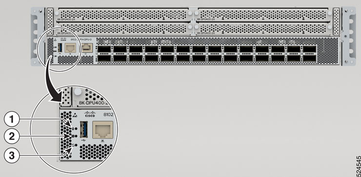
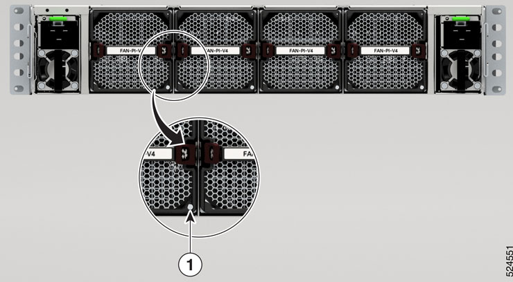
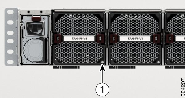
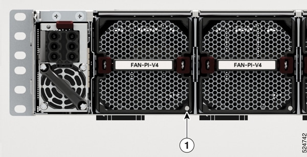
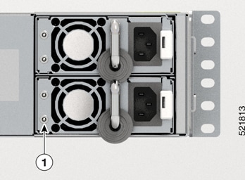
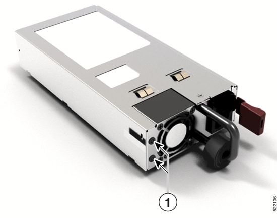
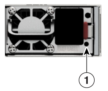
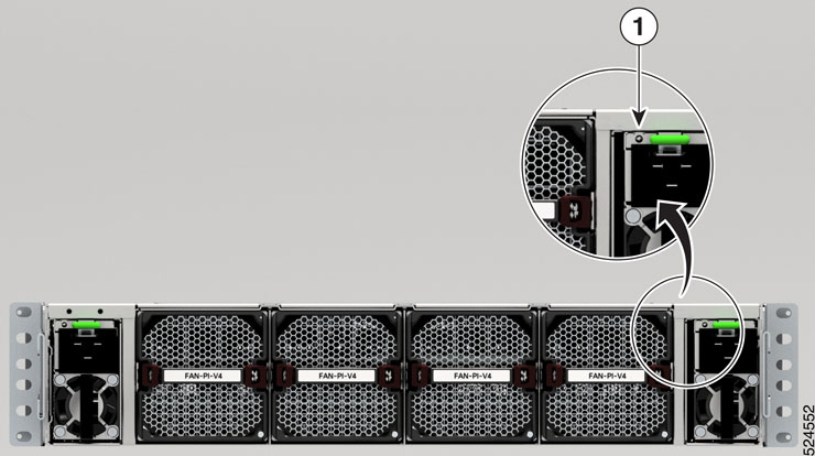
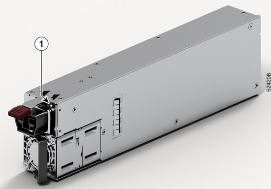
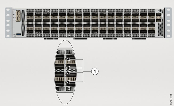
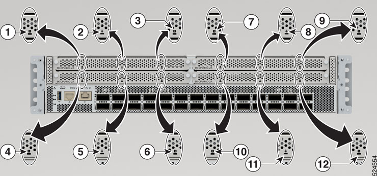
Chassis LEDs
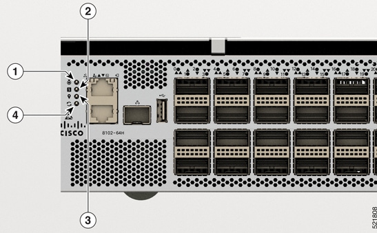
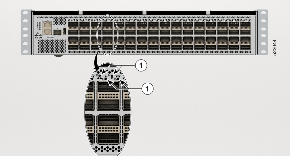
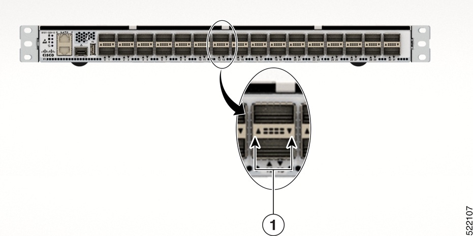
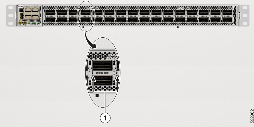
Attention, Status, Synchronization, and GPS LEDs are located both at the far left of the front of the chassis and also on the back of the chassis:
|
1 |
Attention |
|
2 |
Status |
|
3 |
GPS |
|
4 |
Synchronization |
|
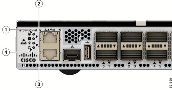
1 |
Attention |
|
2 |
Status |
|
3 |
GPS |
|
4 |
Synchronization |
|
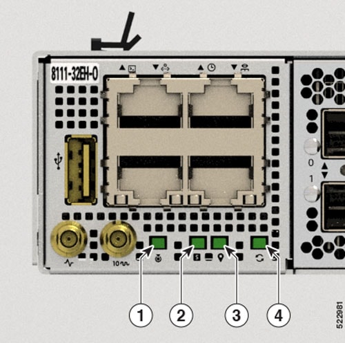
1 |
Attention |
|
2 |
Status |
|
3 |
GPS |
|
4 |
Synchronization |
|
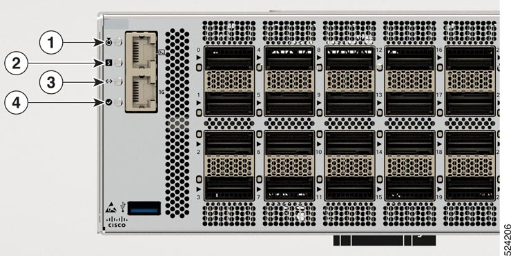
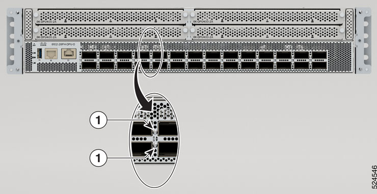
1 |
Attention |
|
2 |
Status |
|
3 |
Activity |
|
4 |
Link |
|
1 |
Attention |
|
2 |
Status |
|
3 |
Synchronization |
|
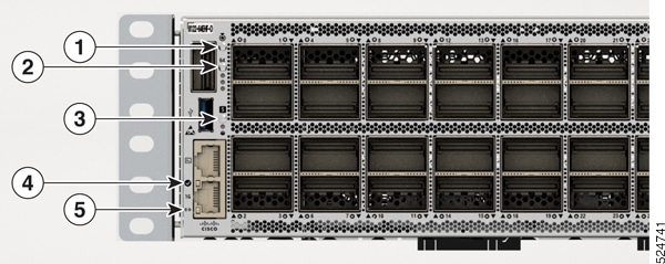
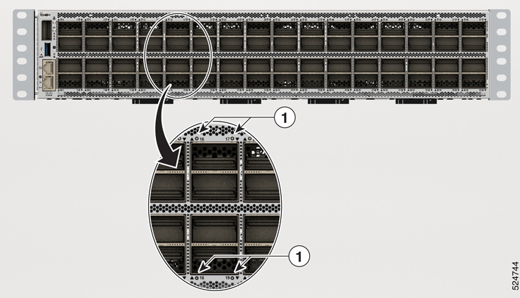
1 |
Attention |
|
2 |
QSFP28 Port 64 Status |
|
3 |
Status |
|
4 |
Link |
|
5 |
Activity |
|
Link  |
Activity  |
Description |
|---|---|---|
|
OFF |
Yellow |
1000Mbps link with no activity |
|
OFF |
Flashing yellow |
1000Mbps link with activity |
|
Green |
Yellow |
100Mbps link with no activity |
|
Flashing green |
Flashing yellow |
100Mbps link with activity |
|
Green |
OFF |
10Mbps link with no activity |
|
Flashing green |
OFF |
10Mbps link with activity |
|
OFF |
OFF |
No link |
| LED | Color | Status |
|---|---|---|
|
Attention
|
Flashing blue |
The operator has activated this LED to identify this chassis. |
|
Off |
This chassis is not being identified. |
|
|
Status
|
Green |
The module is operational and has no active major or critical alarms. |
|
Flashing Green |
The auto or manual FPD upgrade is in progress. |
|
|
Amber |
The module is in one of the following states:
|
|
|
Flashing Amber |
The module has minor alarm. |
|
|
Red |
Power-up failure which prevents the CPU from booting. |
|
|
Flashing Red |
The module has active major or critical alarms. |
|
|
Off |
The module is powered-off. |
|
|
Synchronization
|
Green |
Time core is synchronized to an external source including IEEE1588. |
|
Amber |
The system is running in holdover or free-run mode and it is not synchronized to an external interface. |
|
|
Off |
The centralized frequency or time and phase distribution is not enabled. |
|
|
GPS
|
Green |
The GPS interface is provisioned and frequency, time of day and phase inputs are all operating correctly. |
|
Off |
The GPS interface is not provisioned, or the GPS inputs are not working correctly. |
|
|
QSFP28 Port 64 Status  |
Green |
The port is in operational state. |
|
Off |
The port is in off state. |


 Feedback