Replace Fan Modules for Cisco 8100 Series Switches
The switch supports the following types of fan modules:
|
switch |
Module Configuration (Air Flow Direction) |
PID |
|---|---|---|
|
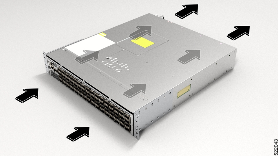
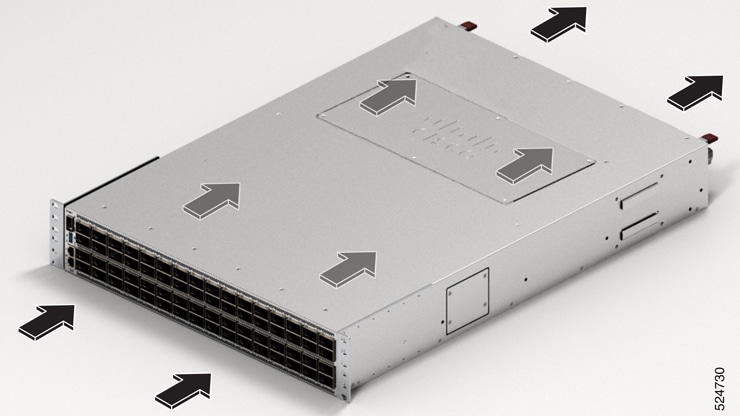
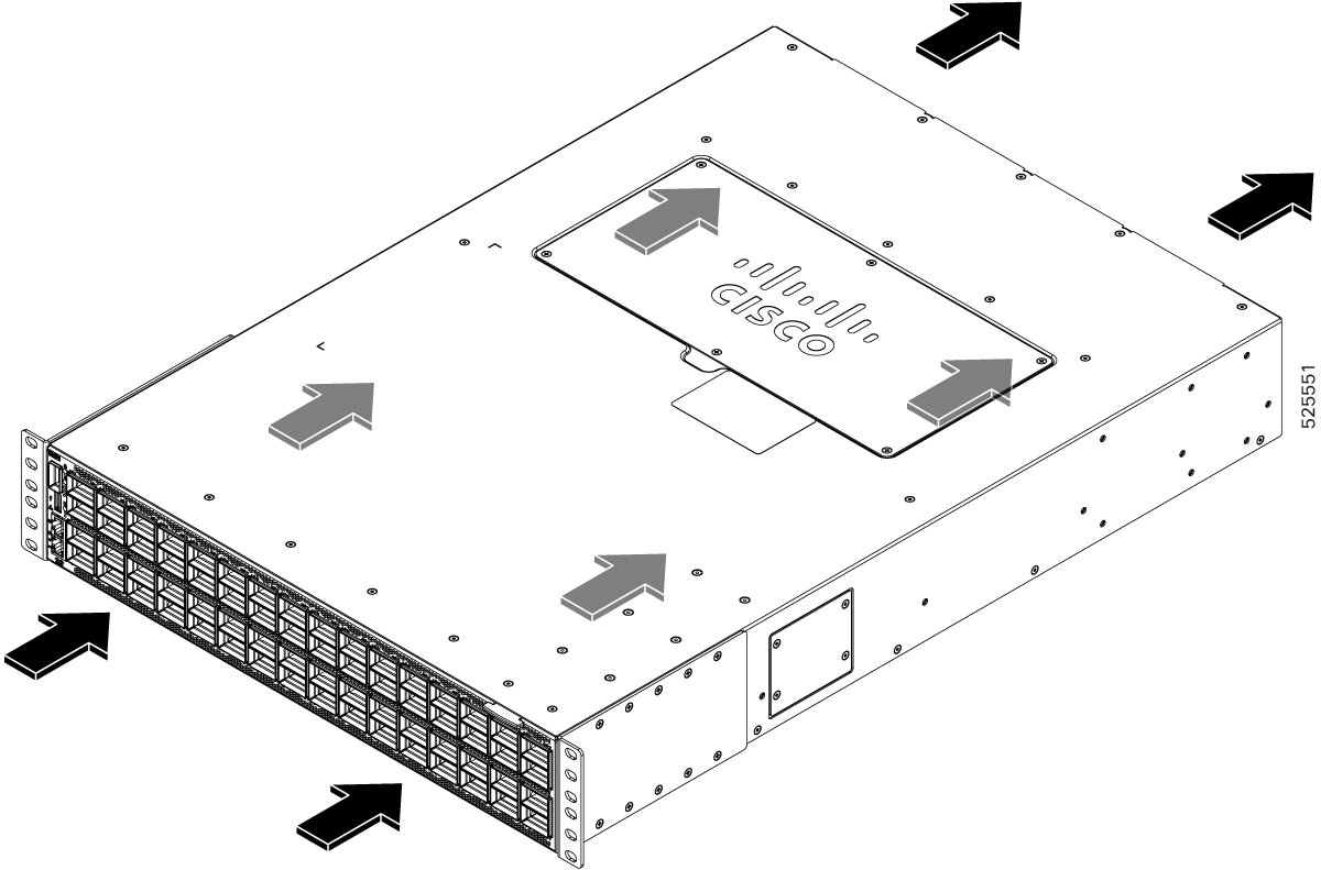
Cisco 8102-64H-O |
Port-side Intake |
FAN-2RU-PI-V2 |
|
Port-side Exhaust |
FAN-2RU-PE-V2 |
|
|
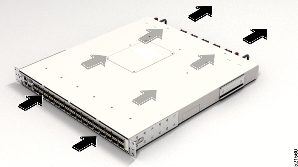
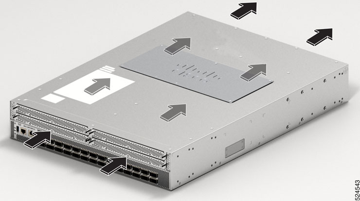
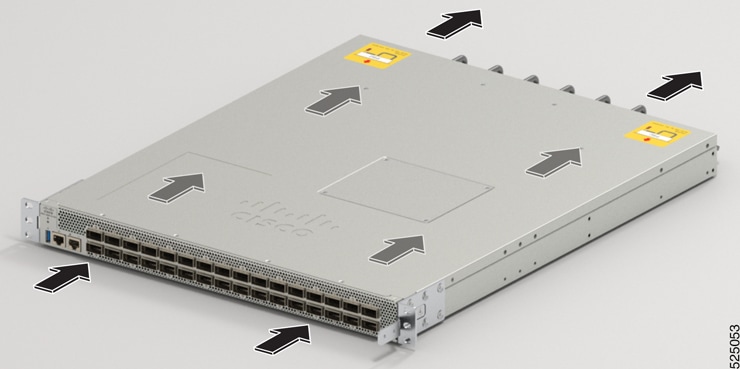
Cisco 8101-32H-O |
Port-side Intake |
FAN-1RU-PI-V2 |
|
Port-side Exhaust |
FAN-1RU-PE-V2 |
|
|
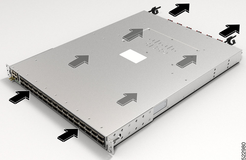
Cisco 8111-32EH-O |
Port-side Intake |
FAN-1RU-PI-V2 |
|
Cisco 8101-32FH-O |
Port-side Intake |
FAN-1RU-PI-V2 |
|
Port-side Exhaust |
FAN-1RU-PE-V2 |
|
|
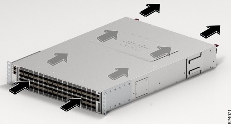
Cisco 8122-64EH-O |
Port-side Intake |
FAN-2RU-PI-V3 or FAN-2RU-PI-V4 |
|
Cisco 8102-28FH-DPU-O |
Port-side Intake |
FAN-2RU-PI-V4 |
|
Cisco 8122-64EHF-O |
Port-side Intake |
FAN-PI-V4 |
|
Cisco 8101-32FH-O-C01 |
Port-side Intake |
FAN-1RU-PI-C01 |
 Note |
Port-Side Exhaust (PSE) configuration is not supported on these switches:
|
Note |
The airflow direction must be the same for all power supply and fan modules in the chassis. Depending upon the required airflow direction, you can change the fan type. You must then also change the power supply. |
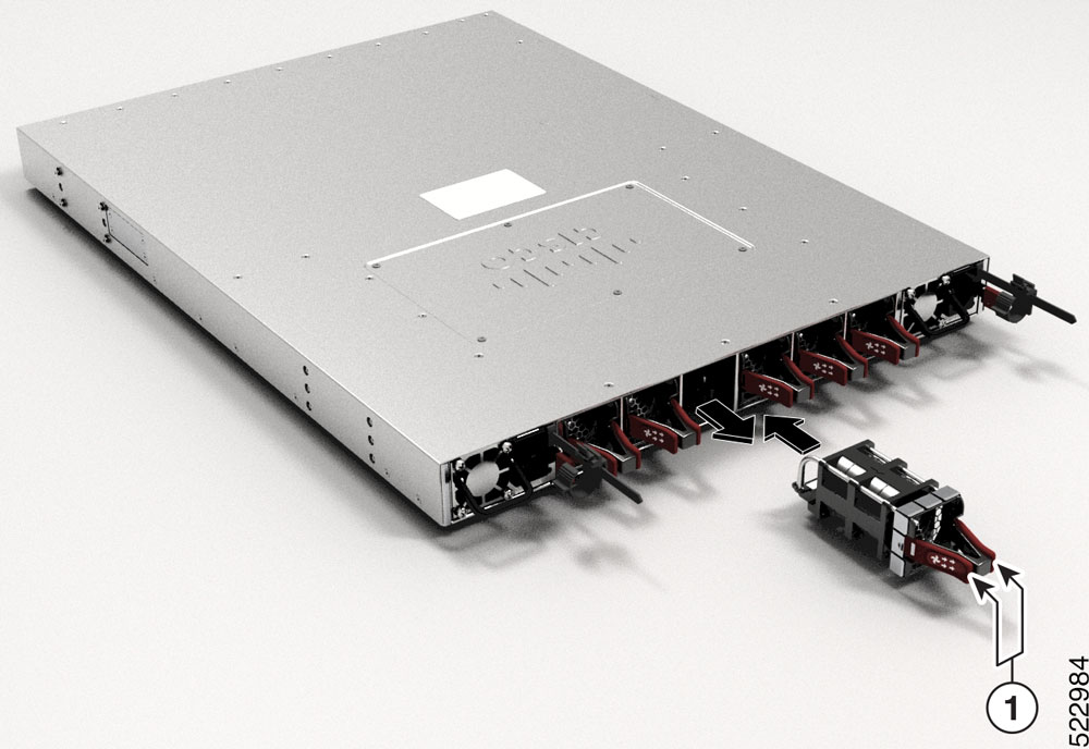
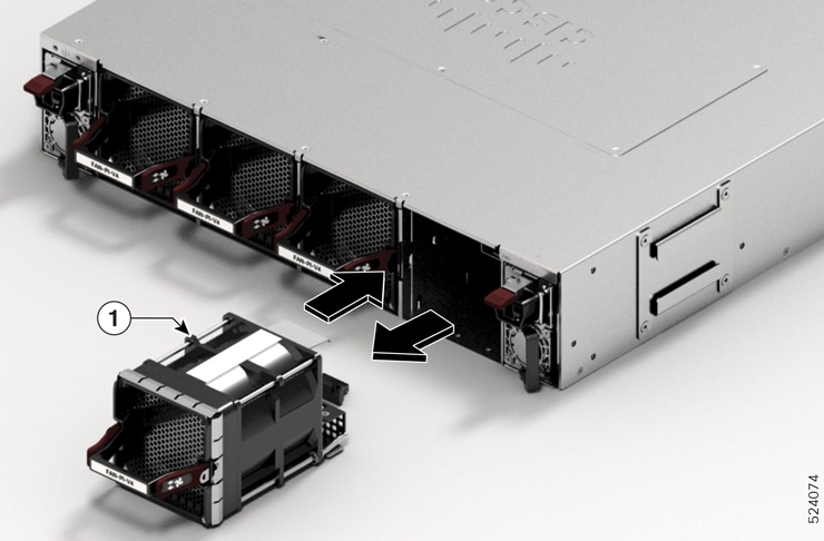
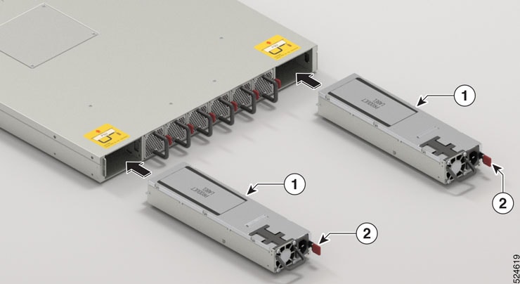
Procedure
|
Step 1 |
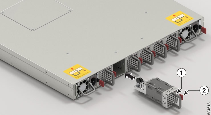
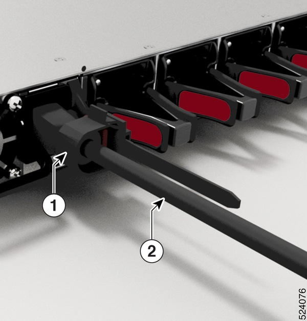
To remove a fan module, follow these steps:
|
||||||
|
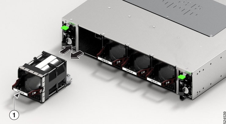
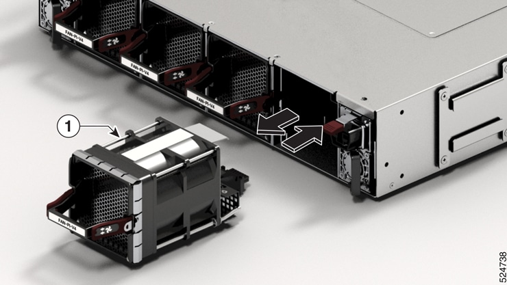
Step 2 |
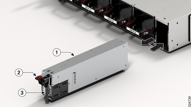
To install a fan module, follow these steps: |


 Feedback