Cisco ASR 9000 Series Aggregation Services Router Hardware Installation Guide
Bias-Free Language
The documentation set for this product strives to use bias-free language. For the purposes of this documentation set, bias-free is defined as language that does not imply discrimination based on age, disability, gender, racial identity, ethnic identity, sexual orientation, socioeconomic status, and intersectionality. Exceptions may be present in the documentation due to language that is hardcoded in the user interfaces of the product software, language used based on RFP documentation, or language that is used by a referenced third-party product. Learn more about how Cisco is using Inclusive Language.
See the Regulatory
Compliance and Safety Information for the Cisco ASR 9000 Series Router document
for additional safety and compliance information,
Caution
This router is not designed to be installed as a shelf-mounted or a free-standing router. The router must be installed in
a rack that is secured to the building structure. You must install the router in either a telco-style frame or a 4-post equipment
rack.
Installation
Overview
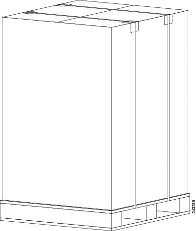
The following figure
shows how the Cisco ASR 9010 Router is shipped and strapped to a shipping
pallet.
Figure 1. Cisco ASR 9010 Router Packaged on a Shipping Pallet
A fully equipped router with six power modules can weigh as much as 375 lbs (170.5 kg); an empty chassis weighs 150 lbs (67.8
kg). The chassis is designed to be lifted by two persons after you remove some of the components, such as line cards, power supplies, and the fan tray, to reduce the weight before lifting
the chassis. See Removing Components Before Installing the Chassis for procedures to remove these components.
1/4-inch (6.35-mm) and 3/16-inch (4.5-mm) flat-blade screwdrivers
Tape measure
Level (optional)
Minimum of 10 slotted binderhead screws (usually provided with the rack) to secure the chassis to the mounting flanges (also
called rails ) in the rack. Five screws should be installed on each side of the chassis.
The following instructions describe how to unpack the Cisco ASR 9000 Series Router from its shipping container.
Unpacking the Cisco
ASR 9006 Router
Follow these steps
to unpack the Cisco ASR 9006 Router from its shipping container (see the figure
below).
Procedure
Step 1
Cut the straps
that secure the cardboard shipping container to the pallet.
Step 2
Remove the
cardboard shipping container.
Step 3
Remove the
packaging material (see the figure below).
Remove the
foam packaging material from the top of the router.
Remove all
screws that secure the four hold-down brackets to the router chassis. The
forward hold-down brackets are secured to the router mounting brackets by two
screws. The rear hold-down brackets are secured to the chassis by four screws.
Remove two
bolts per hold-down bracket that secure the brackets to the pallet.
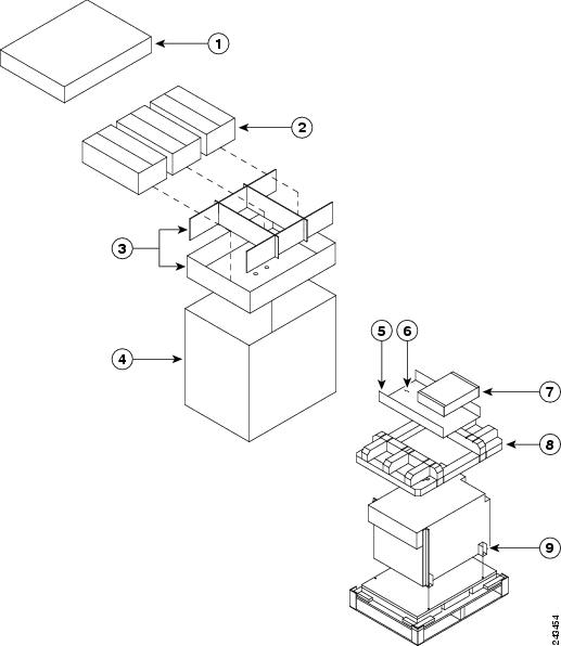
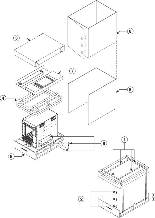
Figure 2. Unpacking the Cisco ASR 9006 Router from the Shipping Container and Pallet
1
Top cardboard packaging cap
4
Cardboard packaging container
7
Chassis accessories
2
Three packaged power modules
5
Cardboard accessory tray
8
Foam packaging material- top cap
3
Cardboard packaging dividers
6
Accessories and power cables
9
Hold-down brackets (four places)
Step 4
Remove
components, such as line cards, power supplies, and the fan tray, to reduce the
weight before lifting or moving the chassis. See
Removing Components Before Installing the Chassis
for more information.
Step 5
Save the
packaging materials in case the router needs repackaging or shipping.
Unpacking the Cisco ASR 9010 Router
Follow these steps to unpack the Cisco ASR 9010 Router from its shipping container.
Procedure
Step 1
Cut the straps that secure the cardboard shipping container to the pallet.
Step 2
Remove the cardboard shipping container.
Step 3
Remove the packaging material.
Remove the foam packaging material from the top of the router.
Remove all screws that secure the four hold-down brackets to the router chassis. The forward hold-down brackets are secured
to the router mounting brackets by two screws. The rear hold-down brackets are secured to the chassis by four screws. Save
these four screws used to hold the rear bracket to the chassis to use later to attach the ground strap.
Step 4
Remove two bolts per hold-down bracket that secure the brackets to the pallet.
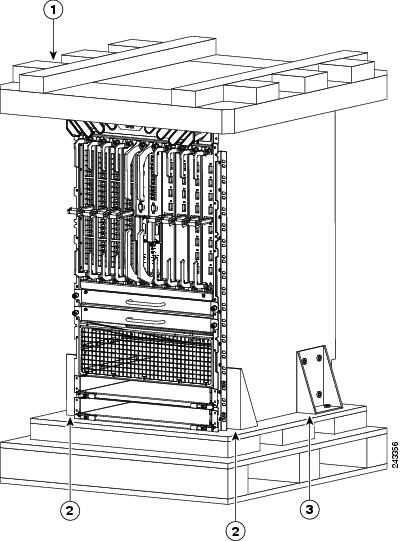
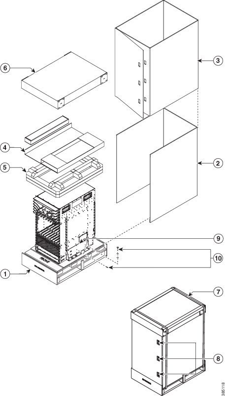
Figure 3. Unpacking the Cisco ASR 9010 Router from the Shipping Container and Pallet
1
Foam packaging material- top cap
2
Front hold-down bracket secured by two screws to the chassis mounting brackets, and by two bolts to the pallet (two places)
3
Rear hold-down bracket secured by four screws to the chassis, and by two bolts to the pallet (two places)
Step 5
Remove components, such as line cards and the fan tray, to reduce the weight before lifting or moving the chassis. See the
Removing Components Before Installing the Chassis for more information.
Step 6
Save the packaging materials in case the router needs repackaging or shipping.
Unpacking the Cisco
ASR 9904 Router
Follow these steps
to unpack the Cisco ASR 9904 Router from its wooden shipping container.
Procedure
Step 1
Cut the straps
that secure the cardboard shipping container to the pallet.
Step 2
Remove the
corrugated top shipping container.
Step 3
Remove the
accessories and corrugated packing accessory tray.
Step 4
Remove the
packing material (see the figure below).
Remove the
foam packaging material from the top of the router.
Remove the
plastic covering from the router and remove it from the bottom foam.
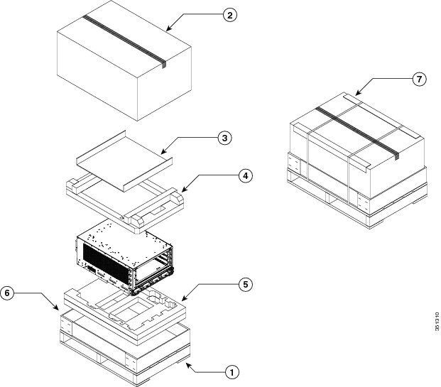
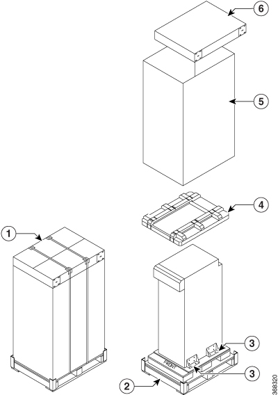
Figure 4. Unpacking the Cisco ASR 9904 Router from the Shipping Container and Pallet
1
Shipping pallet
4
Foam packaging material(top cap)
7
Cardboard shipping container
2
Top corrugated packaging cap
5
Foam packaging material (bottom cap)
3
Corrugated packaging accessory tray
6
Corrugated packaging (lower tray)
Step 5
Remove
components, such as line cards, power supplies, and the fan tray, to reduce the
weight before lifting or moving the chassis. See
Removing Components Before Installing the Chassis
for more information.
Step 6
Save the
packaging materials in case the router needs repackaging or shipping.
Unpacking the Cisco ASR 9906 Router
Follow these steps to unpack the Cisco ASR 9906 Router from its shipping container (see the figure below).
Procedure
Step 1
Cut the straps that secure the cardboard shipping container to the pallet.
Step 2
Remove the three connecting clips.
Step 3
Remove the cardboard shipping container.
Step 4
Remove the accessory tray and chassis accessories.
Step 5
Remove the packaging material (see the figure below).
Remove the foam packaging material from the top of the router.
Remove all screws that secure the two hold-down brackets to the router chassis.
Remove four bolts per hold-down bracket that secure the brackets to the pallet.
Figure 5. Unpacking the Cisco ASR 9906 Router from the Shipping Container and Pallet
1
Straps
5
Shipping pallet
2
Connecting clips
6
Hold-down bracket and screws
3
Top cardboard packaging cap
7
Cardboard accessory tray and chassis accessories
4
Foam packaging material
8
Cardboard packaging container
Step 6
Remove components, such as line cards, power supplies, and the fan tray, to reduce the weight before lifting or moving the
chassis. See Removing Components Before Installing the Chassis for more information.
Step 7
Save the packaging materials in case the router needs repackaging or shipping.
Unpacking the Cisco
ASR 9910 Router
Follow these steps
to unpack the Cisco ASR 9910 Router from its shipping container.
Procedure
Step 1
Cut the straps
that secure the cardboard shipping container to the pallet.
Step 2
Remove the
cardboard shipping container.
Step 3
Remove the
packaging material (see the figure below).
Remove the
foam packaging material from the top of the router.
Remove all
screws that secure the two brackets to the router chassis. Save these screws
used to hold the bracket to the chassis to use later to attach the ground
strap.
Step 4
Remove two
bolts per hold-down bracket that secure the brackets to the pallet.
Figure 6. Unpacking
the Cisco ASR 9910 Router from the Shipping Container and Pallet
Save the
packaging materials in case the router needs repackaging or shipping.
Unpacking the Cisco
ASR 9912 Router
Follow these steps
to unpack the Cisco ASR 9912 Router from its wooden shipping container.
Procedure
Step 1
Cut the straps that secure the cardboard shipping container to the pallet.
Step 2
Remove the cardboard shipping container.
Step 3
Remove the packaging material (see the figure below).
Remove the foam packaging material from the top of the router.
Remove all screws that secure the four brackets to the router chassis. Save these screws used to hold the bracket to the
chassis to use later to attach the ground strap.
Remove two bolts per hold-down bracket that secure the brackets to the pallet.
Figure 7. Unpacking the Cisco ASR 9912 Router from the Shipping Container and Pallet
Save the packaging materials in case the router needs repackaging or shipping.
Unpacking the Cisco
ASR 9922 Router
Follow these steps
to unpack the Cisco ASR 9922 Router from its wooden shipping container.
Procedure
Step 1
Remove any
strapping on the outside of the crate.
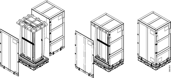
Step 2
Remove the
crate cap door. Disengage the twist locks located along the bottom first. Then,
disengage the twist locks located along the sides, working your way up from the
bottom to the top. Refer to the right and middle figures in
Unpacking the Cisco ASR 9922 Router from the Shipping Container.
Two people
are required to evenly slide the crate cap back off of the plastic pallet base.
Step 4
Remove the foam
packaging material from the top of the router.
Figure 8. Unpacking the Cisco ASR 9922 Router from the Shipping Container
Step 5
Using a 5/16”
wrench or ratchet, remove the four attachment bolts and cross-brace from the
shipping rack (see the figure below).
Figure 9. Cross-brace and Attachment Bolts on the Shipping Rack
Step 6
Use a Phillips
screwdriver to unscrew the rear mounting flange from the system and rack.
Step 7
Use a Phillips
screwdriver to unscrew the front mounting flange from the rack.
Step 8
Remove two
bolts per hold-down bracket that secure the brackets to the pallet (see the
figure below).
Figure 10. Hold-Down
Brackets on the Cisco ASR 9922 Router Shipping Pallet
Note
Do not
unbolt the shipping rack from the pallet.
Step 9
Save the rear
brackets and screws from the shipping packaging for reuse in rack mounting of
the chassis (see the figure below).
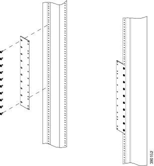
Note
The two
guide rails at the bottom of the rack come in the ASR-9922-ACC-KIT accessory
kit.
Figure 11. Rack Mount
Installation Kit for the Cisco ASR 9922 Router
Step 10
Remove
components, such as line cards and fan trays, to reduce the weight before
lifting or moving the chassis. See
Removing Components Before Installing the Chassis
for procedures showing how to remove these components.
Step 11
Save the
packaging materials in case the router needs to be repackaged for shipping.
Positioning the Router
Positioning the Cisco ASR 9006 Router, Cisco ASR 9010 Router, Cisco 9904 Router, Cisco ASR 9906 Router, Cisco ASR 9910 Router,
and Cisco ASR 9912 Router
Use a safety hand truck to move the Cisco ASR 9006 Router, Cisco ASR 9010 Router, Cisco ASR 9904 Router, Cisco ASR 9906 Router,
Cisco ASR 9910 Router, or Cisco ASR 9912 Router to its final location for rack installation.
Positioning the Cisco ASR 9922 Router
The Cisco ASR 9922 Router ships in a carton similar to the CRS-1 16-Slot shipping carton. Each chassis is installed in a
shipping rack used only for shipping purposes. Remove the chassis from the shipping rack before installing it into the rack.
To prepare the
19-inch 45-RU rack:
Procedure
Step 1
Install the two
guide rails onto the bottom of the rack.
The guide rails are included with the ASR-9922-ACC-KIT accessory kits. Each accessory kit ships with the chassis and includes
the guide rails, grounding lug, associated hardware, and a warranty card.
Step 2
Use screws to
fasten these two guide rails onto the front and rear rails of the rack.
The two guide
rails at the bottom of the rack (Unpacking the Cisco ASR 9922 Router)
have six holes (three per rail) that accommodate 12-24 or M6 screws. If you are
using smaller 10-32 screws, you must use bushings to fit the larger holes (see
the figure below).
Figure 12. One 10-32
Screw with Bushings in Guide Rail Holes
Note
Delrin
bushings with part number 17234-D-1 can be obtained from ASM at
www.accuratescrew.com.
Step 3
Remove the
shipping carton, plastic covering, rear brackets, attachment screws and bolts,
shipping rack bar, and any cosmetic accessories included with the chassis.
Step 4
Use a scissors
jack to remove the chassis from the shipping rack. Place a pallet jack next to
the chassis inside the shipping rack and push/pull the chassis onto the pallet
jack for transport to the rack.
Caution
Tilt the
chassis only when absolutely necessary. The chassis is large and heavy. If it
were to fall, it could cause harm to itself and its surroundings. Before
attempting to tilt the chassis, reduce the weight of the system by removing all
of the components in the chassis. The chassis should then be tilted in a
direction so that the rear of the chassis is facing downward. The distance the
chassis travels without its packaging should be as short as possible.
Step 5
On the rear of
the chassis is an integrated handle which is used to pull the chassis from the
pallet jack into the rack where the chassis is to be installed. Position the
chassis so that the rear handle is facing the front of the rack.
Step 6
From the rear
of the rack, pull the chassis by the handle into the rack, making sure that the
chassis sits on top of the guide rails in the rack.
Step 7
Once the
chassis is pulled into the rack and sits on top of the guide rails, use screws
to fasten the chassis to the rack.
Removing Components Before Installing the Chassis
The Cisco ASR 9000 Series Routers are designed to be lifted for mounting into a rack. To reduce the weight of the system,
you must remove some of the components before attempting to mount it into the rack.
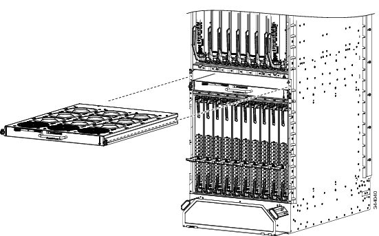
On the Cisco ASR
9922 Router, the third and fourth fan trays (under the middle cage) are
installed upside down compared to the first and second fan trays (above the
middle cage).
Procedure
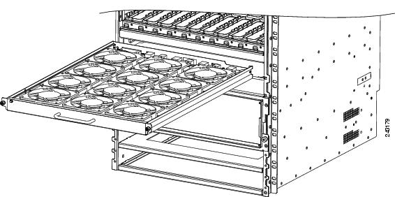
Step 1
Loosen the
captive screw on each side of the fan tray.
Step 2
Using the
handle on the front panel, pull the fan tray halfway out of the chassis.
Note
Wait a few
seconds for all the fans to stop rotating before lifting the fan tray from the
chassis.
Step 3
Slide out the
fan tray completely from the chassis while supporting it with your other hand.
Caution
Use two hands
when handling the fan tray. Each version 1 fan tray weighs about 16 pounds
(7.27 kg). Each version 2 fan tray weighs about 18 pounds (8.18 kg).
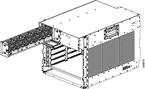
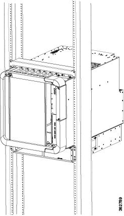
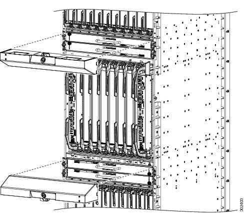
Figure 13. Removing
or Installing the Fan Tray on the Cisco ASR 9010 Router Chassis
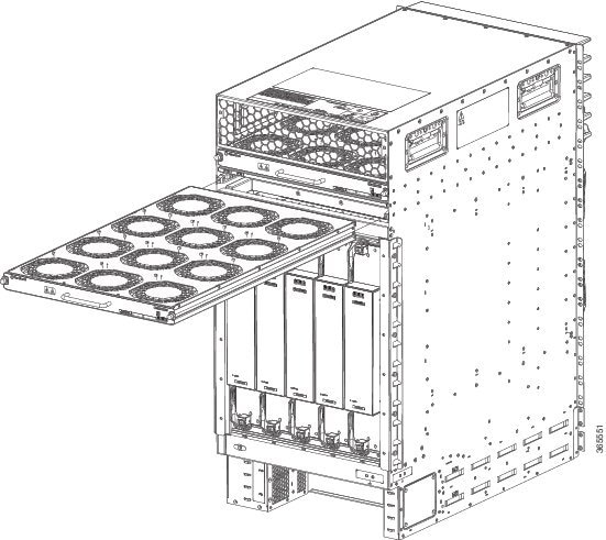
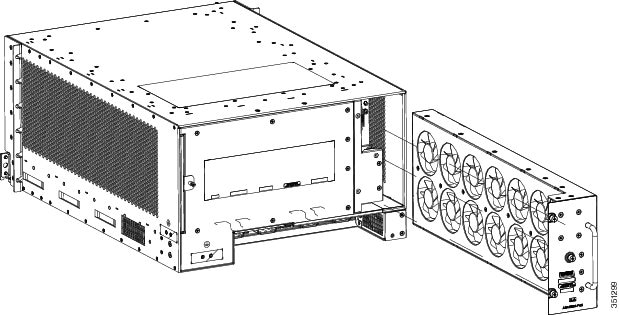
Figure 14. Removing
or Installing the Fan Tray on the Cisco ASR 9910 Router Chassis
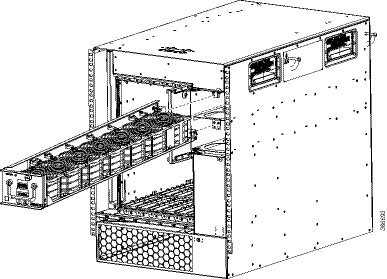
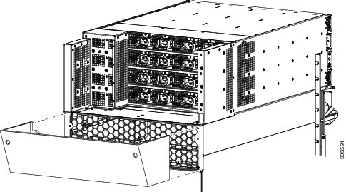
Figure 15. Removing
or Installing the Fan Tray on the Cisco ASR 9922 Router Chassis
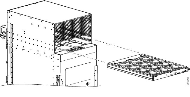
Figure 16. Removing
or Installing the Fan Tray on the Cisco ASR 9912 Router Chassis
Removing a Fan Tray
from the Cisco ASR 9006 Router
Follow these steps
to remove a fan tray from the Cisco ASR 9006 Router (see the figure below).
Procedure
Step 1
Loosen the
captive screw that secures the fan tray door to the chassis and open the door.
Step 2
Loosen the
captive installation screw on the front of the fan tray you want to remove.
Step 3
Using the
handle on the front panel, pull the fan tray halfway out of the chassis.
Note
Wait a few
seconds for all the fans to stop rotating before lifting the fan tray from the
chassis.
Step 4
Slide out the
fan tray completely from the chassis while supporting it with your other hand.
Caution
Use two hands
when handling the fan tray. The fan tray weighs about 7.6 pounds (3.45 kg).
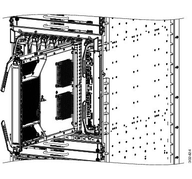
Figure 17. Removing or Installing the Fan Tray on the Cisco ASR 9006 Router Chassis
Removing a Fan Tray
from the Cisco ASR 9904 Router
Follow these steps
to remove a fan tray from the Cisco ASR 9904 Router (see the figure below).
Procedure
Step 1
Loosen the
three captive installation screws on the front of the fan tray.
Step 2
Using the
handle on the front panel, pull the fan tray halfway out of the chassis.
Step 3
Wait a few
seconds for all the fans to stop rotating before lifting the fan tray from the
chassis.
Step 4
Slide out the
fan tray completely from the chassis while supporting it with your other hand.
Caution
Use two hands
when handling the fan tray. The fan tray weighs about 11.0 pounds (4.99 kg).
Figure 18. Removing
or Installing the Fan Tray on the Cisco ASR 9904 Router Chassis
Removing a Fan Tray from the Cisco ASR 9906 Router
Follow these steps to remove a fan tray from the Cisco ASR 9906 Router (see the figure below).
Procedure
Step 1
Loosen the screws that secure the fan tray door to the chassis and open the door.
Step 2
Loosen the captive installation screw on the front of the fan tray.
Step 3
Using the handle on the front panel, pull the fan tray halfway out of the chassis.
Step 4
Wait for all the fans to stop rotating.
Step 5
Slide out the fan tray completely from the chassis while supporting it with your other hand.
Caution
Use two hands when handling the fan tray. The fan tray weighs about 8.0 pounds (3.63 kg).
Figure 19. Removing or Installing the Fan Tray on the Cisco ASR 9906 Router Chassis
Removing Cards from
the Chassis
To reduce additional
weight from the chassis, you can remove all Route Switch Processor (RSP), Route
Processor (RP), Switch Fabric Card (FC), shared port adapter (SPA), SPA
interface processor (SIP), and line cards (LCs).
This section
describes how to remove the RSP cards, RP cards, FCs, and LCs. For information
about removing SPA and SIP cards, see:
Handle all cards by
the metal card carrier edges only; avoid touching the board or any connector
pins. After removing a card, carefully place it in an antistatic bag or similar
environment to protect it from ESD and dust in the optic ports (fiber-optic
line cards).
Caution
Be careful to avoid
damaging the electromagnetic interference (EMI) gasket that runs along the full
height of the card front panel edge. Damage to the EMI gasket can affect the
ability of your system to meet EMI requirements.
Caution
To avoid damaging
card mechanical components, never carry a card by the captive installation
screws or ejector levers. Doing so can damage these components and cause card
insertion problems.
Removing RSP Cards and Line Cards from the Cisco ASR 9006, 9010, 9904, 9906, and 9910 Routers
This section describes how to remove RSP and line cards from the Cisco ASR 9006 Router, Cisco ASR 9010 Router, Cisco ASR
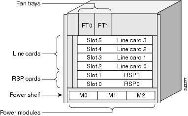
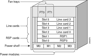
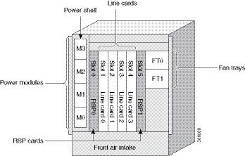
9904 Router, Cisco ASR 9906 Router, and Cisco ASR 9910 Router. The below table and Table 1) and describe the router components and slot numbering for each router.
Table 1. Router Components and Slot Numbering for the Cisco ASR 9006 Router, Cisco ASR 9010 Router, Cisco ASR 9904 Router, Cisco ASR
9906 Router, and Cisco ASR 9910 Router
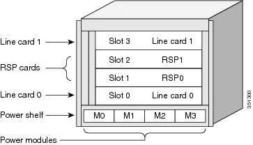
One line card installed in the top slot (labeled LC1). Two RSP cards installed in the middle two slots (labeled RSP1 and RSP0)
located between the line cards (LC0 and LC1).
One line card installed in the lowest slot (LC0) located above the power modules.
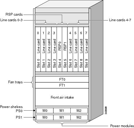
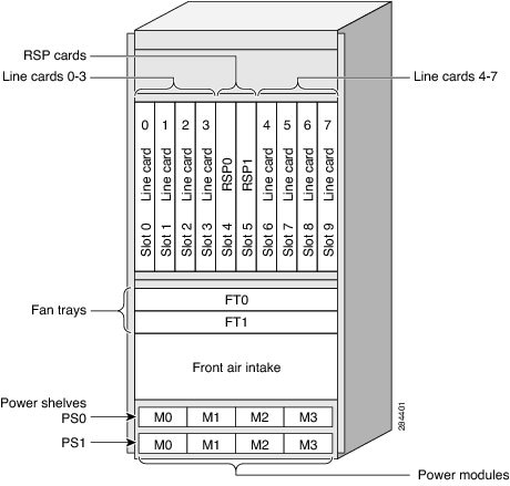
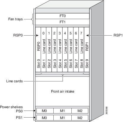
Two RSP cards installed in the two slots (labeled RSP0 and RSP1)
Eight line cards installed in slots LC0 through LC7.
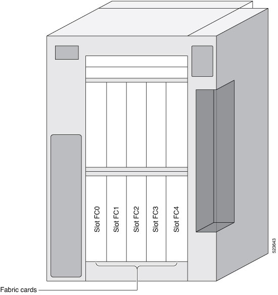
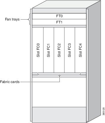
Up to 5 fabric cards and mounted from rear of the chassis.
Figure 20. Cisco ASR 9006 Router Components and Slot Numbering with Version 1 Power System
Figure 21. Cisco ASR 9006 Router Components and Slot Numbering with Version 2 DC Power System
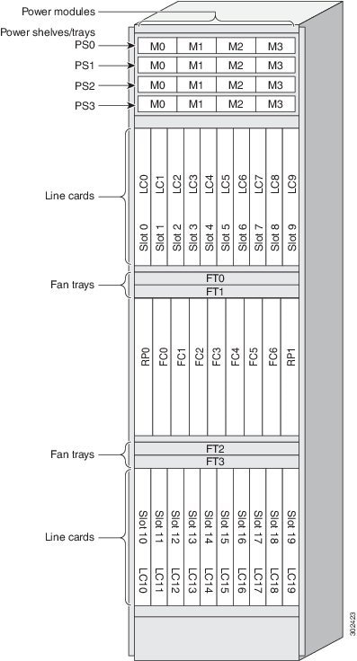
Figure 22. Cisco ASR 9010 Router Components and Slot Numbering with Version 1 Power System or Version 3 AC Power System
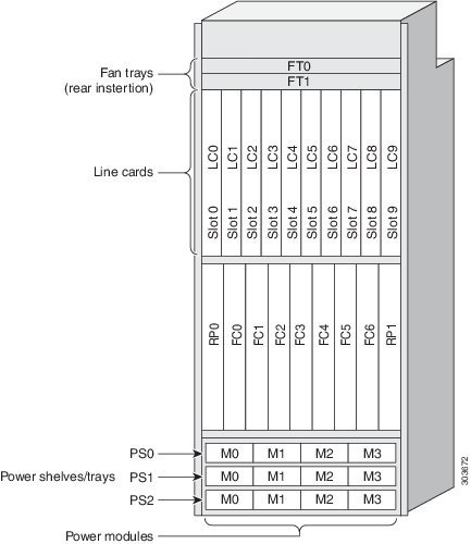
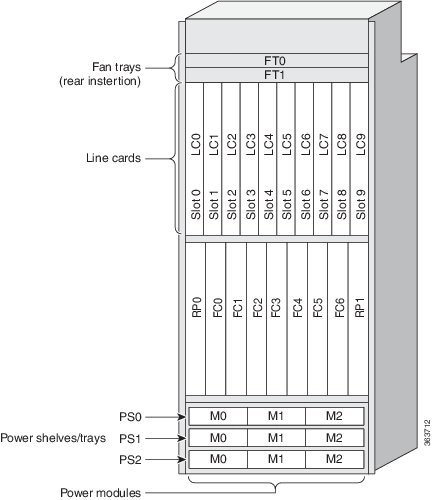
Figure 23. Cisco ASR 9010 Router Components and Slot Numbering with Version 2 Power System or Version 3 DC Power System
Figure 24. Cisco ASR 9904 Router Components and Slot Numbering with Version 2 DC Power System
Figure 25. Cisco ASR 9906 Router Components and Slot Numbering with Version 3 AC Power System
Figure 26. Cisco ASR 9906 Router Components and Slot Numbering with Version 3 DC Power System
Figure 27. Cisco ASR 9910 Router Components and Slot Numbering with Version 3 AC Power System
Figure 28. Cisco ASR 9910 Router Components and Slot Numbering with Version 3 DC Power System
Figure 29. Cisco ASR 9906 Router Components and Slot Numbering for Fabric Cards
Figure 30. Cisco ASR 9910 Router Components and Slot Numbering for Fabric Cards
Follow these
steps to remove RSP and line cards from the chassis.
Procedure
Step 1
Refer to the above figures to identify each card and write down the card type and slot number on a piece of paper. You will
need this information when you reinstall the cards in the chassis to be sure you reinstall each card in its original slot.
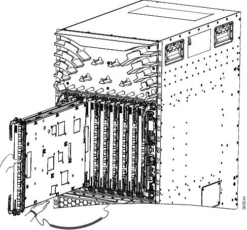
Step 2
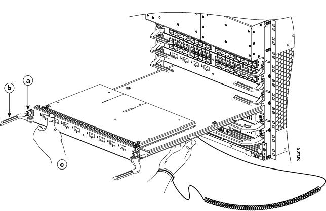
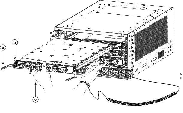
To remove a card starting at the lowest numbered slot:
Use a screwdriver to loosen the captive screws at the ends of the line card front panel.
Pivot the ejector levers to unseat the card from the backplane connector.
Slide the card out of the slot and place it directly into an antistatic bag or other ESD-preventive container.
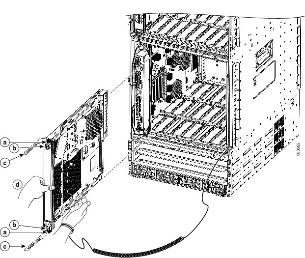
Figure 31. Removing a Line Card from the Cisco ASR 9006 Router Chassis
a
Loosen the captive screws.
b
Pivot the ejector levers to unseat the card from the backplane connector.
c
Slide the card out of the chassis.
Figure 32. Removing a Line Card from the Cisco ASR 9010 Router Chassis
a
Loosen the captive screws.
b
Pivot the ejector levers to unseat the card from the backplane connector.
c
Slide the card out of the chassis.
Figure 33. Removing a Line Card from the Cisco ASR 9904 Router Chassis
a
Loosen the captive screws.
b
Pivot the ejector levers to unseat the card from the backplane connector.
c
Slide the card out of the chassis.
Figure 34. Removing a Line Card from the Cisco ASR 9906 Router Chassis
a
Loosen the captive screws.
b
Pivot the ejector levers to unseat the card from the backplane connector.
c
Slide the card out of the chassis.
Figure 35. Removing a Line Card from the Cisco ASR 9910 Router Chassis
Step 3
Repeat for each RSP or line card.
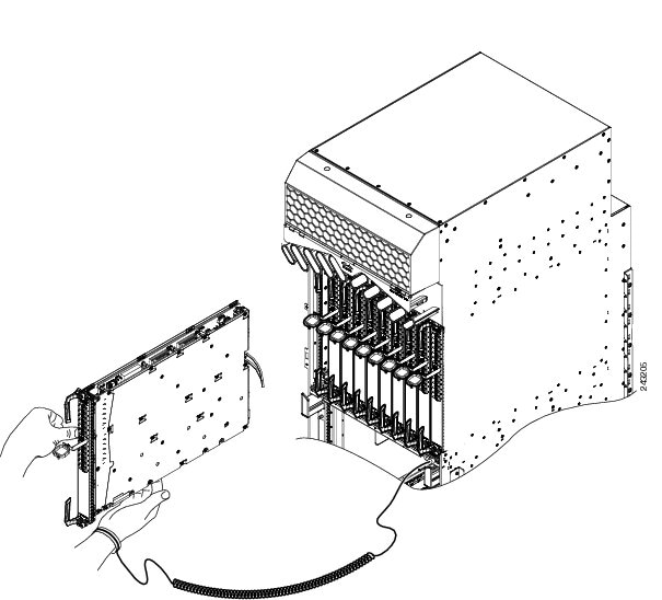
Removing RP Cards,
Fabric Cards, and Line Cards from the Cisco ASR 9922 Router and Cisco ASR 9912
Router
This section
describes how to remove the Route Processor (RP) cards, Fabric Card (FC), and
Line Cards (LCs) from the Cisco ASR 9922 Router and Cisco ASR 9912 Router. The
table below describes the components and slot numbering for each router.
Table 2. Router
Components and Slot Numbering for the Cisco ASR 9922 Router and Cisco ASR 9912
Router
Up to seven FC cards installed between the two RP cards above the power trays.
Ten line cards installed in slots 0 through 9 below the fan trays.
Figure 36. Cisco ASR 9922
Router Components and Slot Numbering with Version 2 DC Power
System
Figure 37. Cisco ASR 9922
Router Components and Slot Numbering with Version 3 DC Power
System
Figure 38. Cisco ASR 9922
Router Components and Slot Numbering with Version 2 AC Power
System
Figure 39. Cisco ASR 9922
Router Components and Slot Numbering with Version 3 AC Power
System
Figure 40. Cisco ASR 9912
Router Components and Slot Numbering with Version 2 DC Power
System
Figure 41. Cisco ASR 9912
Router Components and Slot Numbering with Version 3 AC Power
System
Follow these steps
to remove RP cards, FCs, and LCs from the Cisco ASR 9922 Router and Cisco ASR
9912 Router chassis.
Use a
screwdriver to loosen the captive screws at the ends of the line card front
panel.
Pivot the
ejector levers to unseat the card from the backplane connector.
Slide the
card out of the slot and place it directly into an antistatic bag or other
ESD-preventive container.
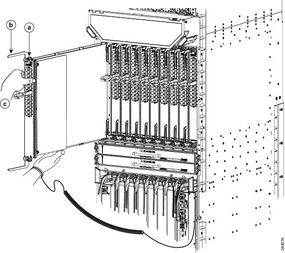
Figure 44. Removing a Line Card from the Cisco ASR 9922 Router Top Card Cage
a
Loosen the captive screws.
b
Pivot the ejector levers outward to unseat the card from the backplane connector.
c
Slide the card out of the chassis.
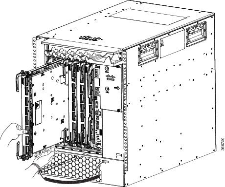
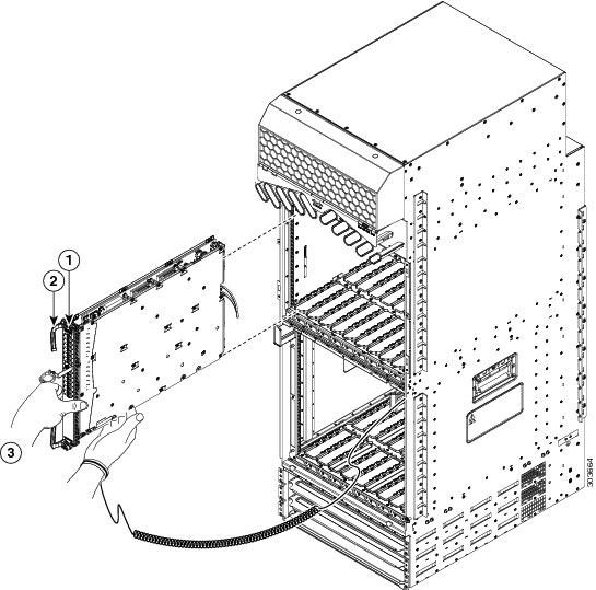
Figure 45. Removing a Line Card from the Cisco ASR 9912 Router Top Card Cage
1
Loosen the captive screws.
2
Pivot the ejector levers outward to unseat the card from the backplane connector.
3
Slide the card out of the chassis.
Step 4
Repeat Step 2
or Step 3 for each FC, LC, and RP card.
Rack-Mounting the
Router Chassis
The router chassis is installed in a front-mounted position, as shown in the Telco 2-Post Rack section.
In a front-mounted
position, the chassis rack-mounting flanges are secured directly to the rack
posts.
Note
The Cisco ASR 9922
Router and Cisco ASR 9912 Router are designed to mount in only 4-post racks.
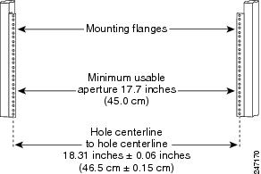
Verifying Rack
Dimensions
Before you install
the chassis, measure the space between the vertical mounting flanges (rails) on
your equipment rack to verify that the rack conforms to the measurements shown
in
Verifying Equipment Rack Dimensions.
Procedure
Step 1
Mark and
measure the distance between two holes on the left and right mounting rails.
The distance
should measure 18.31 inches ± 0.06 inches (46.5 cm ± 0.15 cm).
Note
Measure for
pairs of holes near the bottom, middle and top of the equipment rack to ensure
that the rack posts are parallel.
Step 2
Measure the
space between the inner edges of the left front and right front mounting
flanges on the equipment rack.
The space must
be at least 17.7 inches (45 cm) to accommodate the chassis, which is
approximately 17.50 inches (44.45 cm) wide and fits between the mounting posts
on the rack.
Figure 46. Verifying Equipment Rack Dimensions
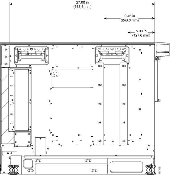
Vertical Rack Rail Locations for ASR 9906 Router
This image shows the vertical rack rail locations for installing the Cisco ASR 9906 router chassis in a 2-post and 4-post
rack:
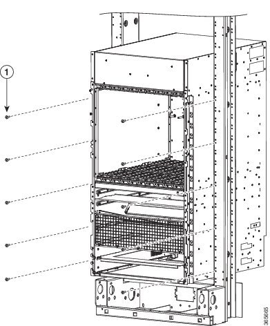
Installing the
Chassis in a 2-Post Rack
This section
describes how to install the chassis in a 2-post telco-style rack. Two people
can lift an empty router chassis using the handles on the sides. To accommodate
racks with different hole patterns in their mounting flanges, the chassis
rack-mounting flanges have three groups of eight oblong screw holes on each
side.
Caution
An empty chassis weighs approximately 150 pounds (68 kg). You need two people to slide the chassis into the equipment rack
safely.
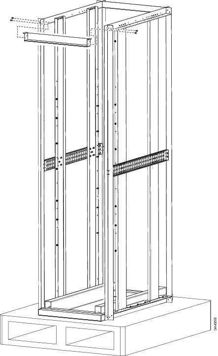
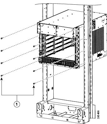
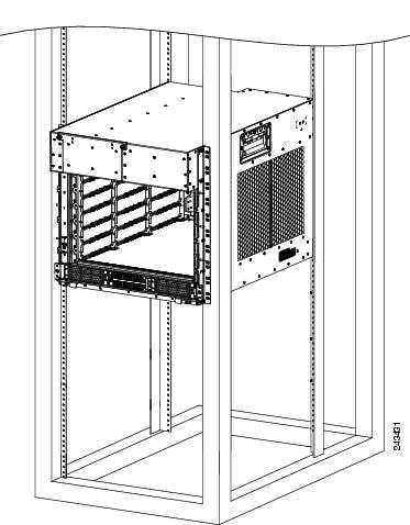
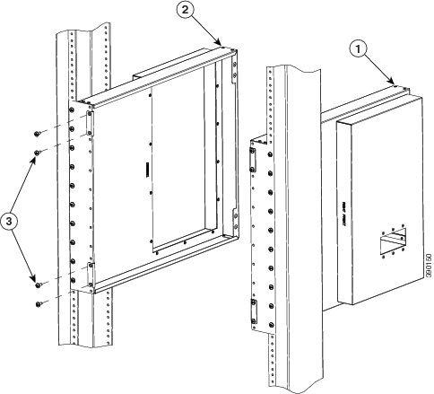
This figure shows
the orientation of the Cisco ASR 9010 Router chassis to the rack posts (3” or
6” channel width) of an industry-standard 2-post rack and components used in
the installation.
Figure 47. Installing the
Cisco ASR 9010 Router Chassis in a Standard 2-Post Rack
1
Five
screws per side (minimum) to attach the router chassis to the rack
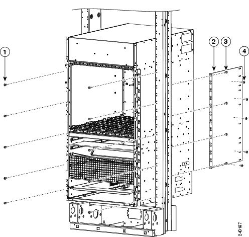
Note
To install the Cisco ASR 9010 Router chassis in a Seismic 2-post rack for optional earthquake protection, two side brackets
must be mounted to the chassis for attachment to the posts (5” channel width) of the GR-63 Zone 4 Seismic 2-post rack.
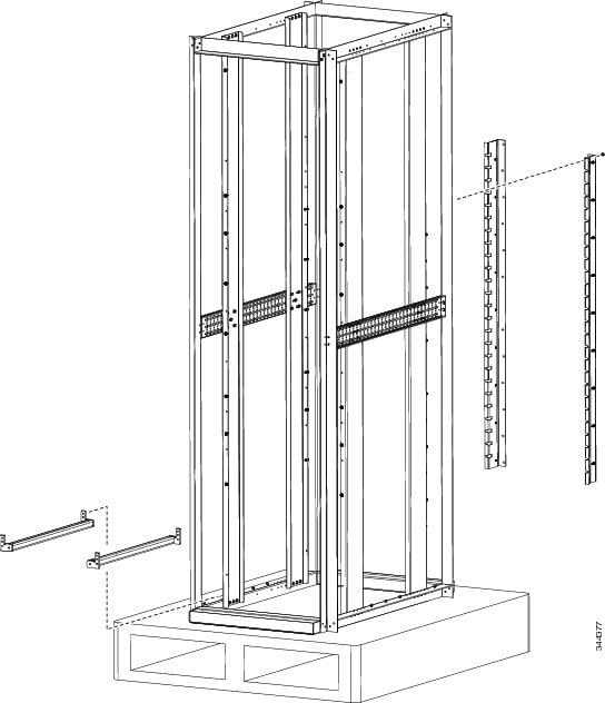
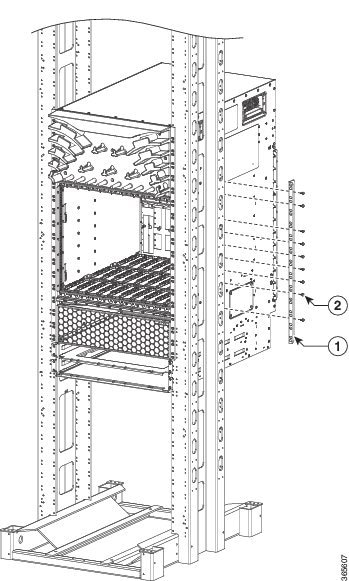
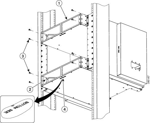
The below figure
shows the orientation of the Cisco ASR 9010 Router chassis to the Seismic
2-post rack and components used in the installation.
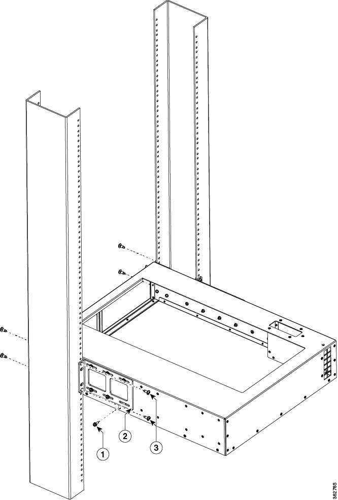
Figure 48. Installing the
Cisco ASR 9010 Router Chassis in a Seismic 2-Post Rack
1
Five screws per side (minimum) to attach the router chassis to the rack
3
Rear mounting bracket
2
Four screws (minimum) to attach the rear mounting bracket to the rack
4
Five screws to attach the rear mounting bracket to the router chassis
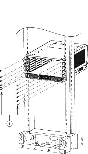
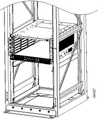
The figure below
shows the orientation of the Cisco ASR 9006 Router chassis to the rack posts
and components used in the installation.
Figure 49. Installing the
Cisco ASR 9006 Router Chassis in a Standard 2-Post Rack
1
Four
screws per side (minimum) to attach the router chassis to the rack.
The figure below
shows the orientation of the Cisco ASR 9904 Router chassis to the rack posts
and components used in the installation.
Figure 50. Installing the
Cisco ASR 9904 Router Chassis in a Standard 2-Post Rack
1
Six
screws per side (minimum) to attach the router chassis to the rack.
The figure below shows the orientation of the Cisco ASR 9906 Router chassis to the rack posts and components used in the
installation.
Figure 51. Installing the Cisco ASR 9906 Router Chassis in a Seismic 2-Post Rack
1
Five screws per side (minimum) to attach the router chassis to the rack.
Figure 52. Installing the Cisco ASR 9906 Router Chassis in a Standard 2-Post
Figure 53. Installing the
Cisco ASR 9910 Router Chassis in a 2-Post Seismic Rack
1
Use screw
and brackets from 2 post rack mount bracket kit.
Follow these steps
to install the chassis in the equipment rack.
Procedure
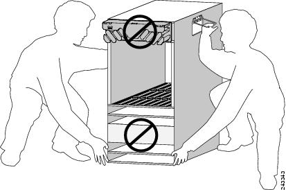
Step 1
Using two
people, lift the chassis into the rack using the side handles and grasping
underneath the power supply bays (see the figure below).
Figure 54. Correct
Lifting Positions
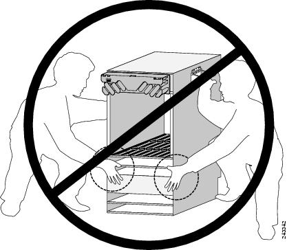
Caution
Do not grasp the card cage or the air inlet grill when lifting the router chassis (see the figure below).
Figure 55. Incorrect
Lifting Handholds
Step 2
Position the
chassis until the rack-mounting flanges are flush against the mounting rails on
the rack.
Step 3
Hold the
chassis in position against the mounting rails while the second person
finger-tightens a screw to the rack rails on each side of the chassis.
Step 4
Finger-tighten the screws to the rack rails on each side of the chassis. Space
the screws evenly between the top and bottom of the chassis.
Step 5
(Optional)
For optional earthquake protection for the Cisco ASR 9010 Router or Cisco ASR
9006 Router, two side brackets must be mounted to the chassis for attachment to
the posts (5” channel width) of a GR-63 Zone 4 Seismic 2-post rack (Installing the
Cisco ASR 9010 Router Chassis in a Seismic 2-Post Rack).
Attach
the side brackets to the left and right side of the chassis by
finger-tightening five screws through each bracket into the chassis.
Attach
the side bracket front flanges to the rack posts by finger-tightening four
screws through each bracket flange into the mounting rails of the rack.
Fully
tighten the five screws on each side bracket to secure the brackets to the
chassis.
Fully
tighten the four screws on each side bracket flange to secure the brackets to
the rack rails.
Step 6
Fully tighten
all five screws on the chassis mounting flanges on each side to secure the
chassis to the rack rails.
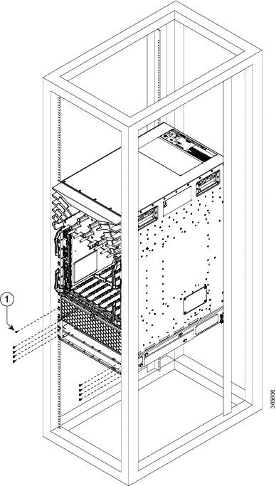
The two guide
rails at the bottom of the rack are included in the ASR-9922-ACC-KIT and
ASR-9912-ACC-KIT accessory kits. Use screws to fasten these two guide rails
into the front and rear rails of the rack.
The two guide
rails have six holes (three per rail) that accommodate 12-24 or M6 screws. If
you want to use smaller 10-32 screws, you must use them with bushings to fit
the larger holes (One 10-32
Screw with Bushings in Guide Rail Holes ).
The bottom rail is keyed to the EIA mounting hole pattern. Install the rails at
the first RU location. The rear rack mount brackets are installed by aligning
the bracket mounting holes to the holes on the rear cover of the chassis.
Step 2
Use a scissors
jack to remove the chassis from the shipping rack. Place a pallet jack next to
the chassis inside the shipping rack and push/pull the chassis onto the pallet
jack for transport to the rack.
Step 3
On the rear of
the Cisco ASR 9922 Router is an integrated handle that is used to pull the
chassis from the pallet jack into the rack where the chassis is to be
installed.
Position
the chassis so that the rear handle is facing the front of the rack.
From the
rear of the rack, pull the chassis by the handle into the rack, making sure
that the chassis sits on top of the guide rails in the rack.
Step 4
On the Cisco
ASR 9912 Router, the handles are on the sides of the chassis. Once the chassis
is pulled into the rack and sits on top of the guide rails, use screws to
fasten the chassis to the rack.
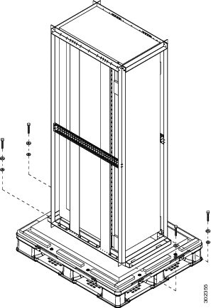
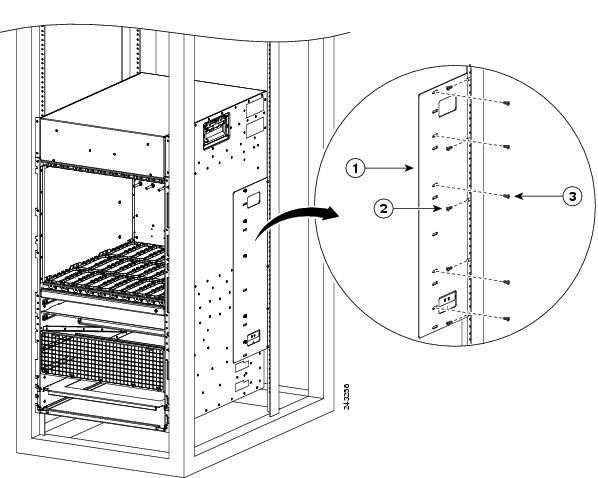
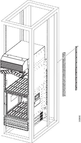
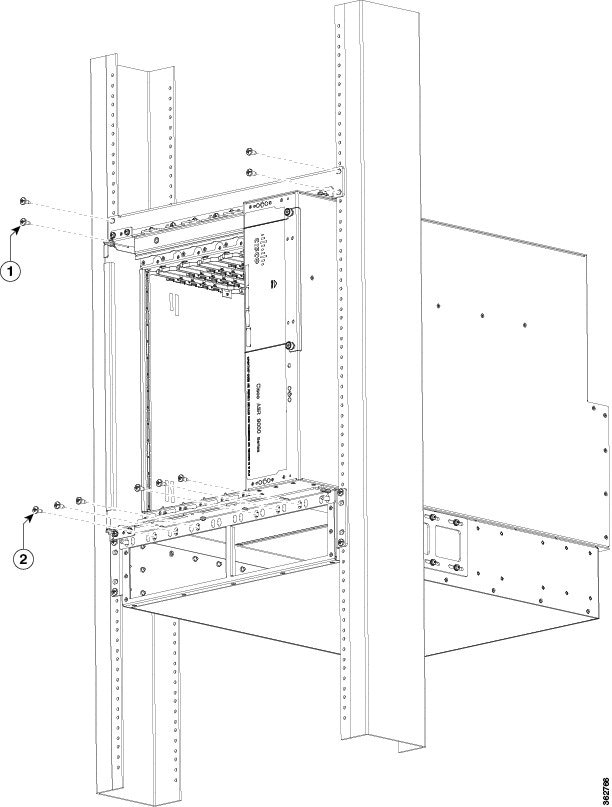
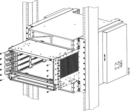
Figure 56. Installing the Cisco ASR 9010 Router Chassis in a 4-Post Rack
1
Rear mounting bracket
2
Five screws (minimum) to attach the rear mounting bracket to the rear post of the rack
3
Five screws (minimum) to attach the rear mounting bracket to the router chassis
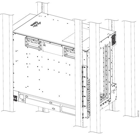
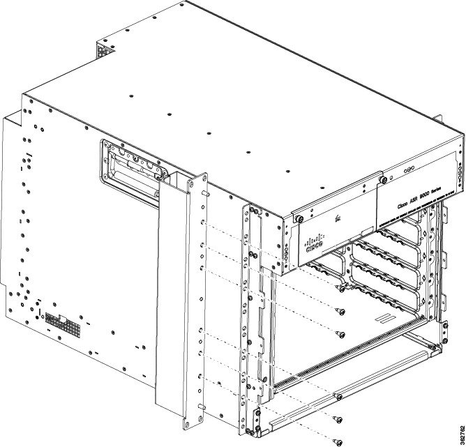
Figure 57. Installing the Cisco ASR 9006 Router Chassis in a 4-Post Rack
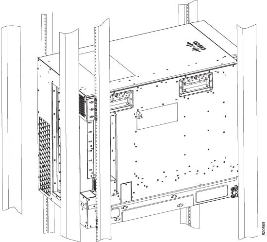
Figure 58. Installing the Cisco ASR 9904 Router Chassis in a 4-Post Rack
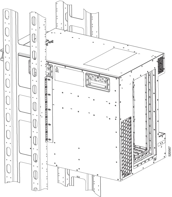
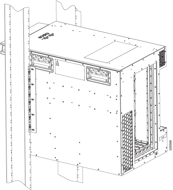
Figure 59. Installing the Cisco ASR 9906 Router Chassis in a 4-Post Rack - Right view
Figure 60. Installing the Cisco ASR 9906 Router Chassis in a 4-Post Rack - Left view
Figure 61. Installing the Cisco ASR 9910 Router Chassis in a 4-Post Rack
1
Use screws to attach the router chassis to the rack.
2
Use screws and four post rack mount brackets from four post rack mount bracket kit for this installation.
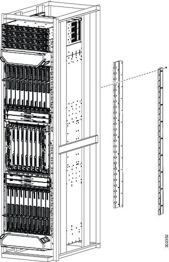
Figure 62. Rack Mount Installation Kit for the Cisco ASR 9922 Router and Cisco ASR 9912 Router
Figure 63. Installing the Cisco ASR 9922 Router Chassis in a 4-Post Rack
Figure 64. Installing the Cisco ASR 9922 Router Chassis in a 4-Post Rack
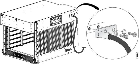
Supplemental Bonding
and Grounding Connections
Before you connect
power to the router, or power on the router for the first time, we recommend
that you connect the central office ground system or Network Equipment Building
System (NEBS) to the threaded supplemental bonding and grounding receptacles on
the router. For more information on supplemental bonding and grounding cable
requirements, see
NEBS
Supplemental Unit Bonding and Grounding Guidelines, page 1-60
.
The table below
references the grounding receptacle locations for the Cisco ASR 9000 Series
Routers.
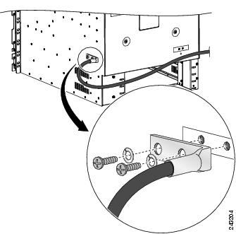
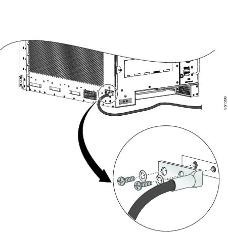
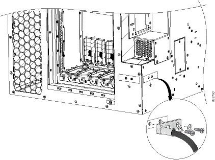
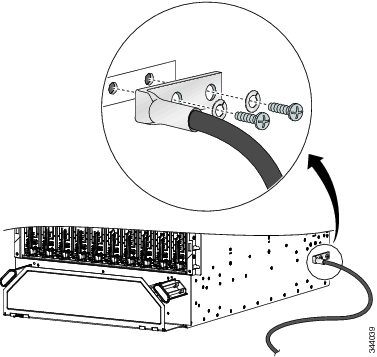
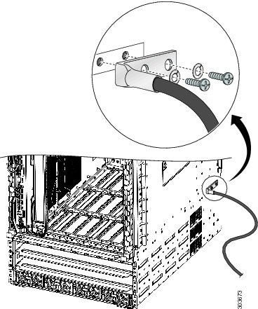
Follow these steps
to attach a grounding cable lug to the router:
Procedure
Step 1
Insert the
grounding screws (10-32 round-head) through the locking washers (ideally
nickel-plated brass) and into the threaded grounding receptacle (has two M6
bolt holes with 0.625 to 0.75 spacing between them). The wire receptacle is
large enough to accept a #6 AWG or larger multi-strand copper wire.
Step 2
Tighten the
grounding screws securely to the receptacles.
Step 3
Prepare the
other end of the grounding wire and connect it to the appropriate grounding
point at your site to ensure an adequate earth ground.
Figure 65. NEBS
Bonding and Grounding for the Cisco ASR 9010 Router
Figure 66. NEBS
Bonding and Grounding for the Cisco ASR 9006 Router
Figure 67. NEBS
Bonding and Grounding for the Cisco ASR 9904 Router
Figure 68. NEBS Bonding and Grounding for the Cisco ASR 9906 Router
Figure 69. NEBS
Bonding and Grounding for the Cisco ASR 9922 Router
Figure 70. NEBS
Bonding and Grounding for the Cisco ASR 9912 Router
Installing Chassis Accessories
The Cisco ASR 9000 Series Routers ship with a base set of chassis accessories. To install the base accessories and optional
accessories, see the appropriate installation procedure below for your router:
Base Accessories
Note
The Cisco ASR 9904 Router and Cisco ASR 9910 Router do not include base chassis accessories.
Optional Accessories
Installing Base
Chassis Accessories on the Cisco ASR 9010 Router
The base chassis
accessories for the Cisco ASR 9010 Router include:
If you did not
order the optional accessory set, follow these steps to install the supplied
base chassis accessories on the Cisco ASR 9010 Router:
Procedure
Step 1
Install two
ball studs (one per side) into the chassis front edge (see the figure below)
near the top of the chassis grill. Tighten the ball studs to a torque of 8
in-lb (0.90 N-m).
Figure 71. Installing
Ball Studs: Version 1 Power Cisco ASR 9010 Router (Base Accessories
Installation)
Attach the
accessory grill to the chassis in front of the chassis grill. The top of the
accessory grill attaches to the ball studs.
Note
You must install the lower fan tray before attaching the accessory grill. The lower fan tray slot is located behind the accessory
grill. See Installing Cards and Modules in the Chassis.
Figure 72. Installing
Base Chassis Accessories on the Cisco ASR 9010 Router
1
Two
are ball studs inserted in front chassis edge threaded holes next to chassis
grill
2
Two
side strips attach to front chassis edge (one per side).
3
Accessory grill attaches to front chassis edge by attaching to ball studs.
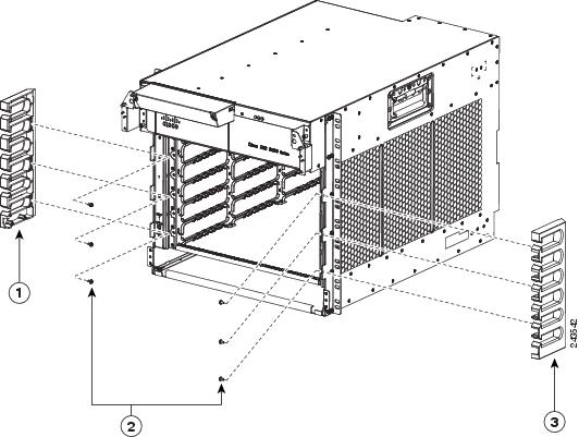
Installing Optional
Chassis Accessories on the Cisco ASR 9010 Router
The optional
chassis accessories for the Cisco ASR 9010 Router include:
Six ball studs
Two L-shaped brackets
Two hinge brackets (left and right side)
Eight screws (plus one extra) for attaching the hinge brackets
Four screws for attaching the L-shaped brackets
Two doors (left and right side)
One mid-cover with door lock
Note
Installation of
the optional accessory pieces also includes the base accessory ball studs and
front grill. The base accessory side strips are not used when installing the
optional chassis accessories.
If you ordered the
optional accessories set, follow these steps to install both the base and
optional accessories (see the figure below):
Procedure
Step 1
Attach the left
L-shaped bracket (item 3 in the figure below) to the left hinge bracket (item 2
in the figure below) with two screws. Tighten the screws to a torque of 5 in-lb
(0.55 N-m).
Step 2
Repeat Step 1
for the right hinge bracket and right L-shaped bracket.
Step 3
Remove the two
screws that secure the bottom edge of the cable management tray to the chassis.
Figure 73. Optional Chassis Accessories for the Cisco ASR 9010 Router
1
Door
(one per side)
5
Screws for attaching the L-shaped bracket to the hinge bracket (one screw is
removed and re-inserted to attach the L-shaped bracket to the cable management
tray and chassis)
2
Hinge
bracket (one per side)
6
Mid-cover with door lock
3
L-shaped bracket (one per side)
7
Balls
studs (three per side)
4
Four
screws for attaching each hinge bracket (eight screws total)
8
Front
grill
Figure 74. Locations
for the Six Ball Studs on the Cisco ASR 9010 Router
Step 5
Attach the left
and right hinge brackets to the chassis using four screws for each bracket.
Tighten the screws to a torque of 11 in-lb (1.20 N-m). The L-shaped brackets
should align with the holes in the cable management tray from which you removed
the screws.
Step 6
Secure the
L-shaped brackets to the chassis and cable management tray by re-inserting and
tightening the cable management tray screws you removed (see the figure below).
Figure 75. Installing
the Hinge Brackets and L-Shaped Brackets on the Cisco ASR 9010
Router
1
Install each hinge bracket, with an L-shaped bracket attached, using four
screws.
2
After
the hinge brackets are installed, secure each L-shaped bracket to the cable
management tray and chassis with the screw that you previously removed from
that location.
Step 7
Install the
mid-cover with door lock (item 6 in
Step 4)
by engaging it to the upper four ball studs and lining up the grooves in the
top outside edges of the mid-cover with ridges at the bottom of the hinge
brackets.
Step 8
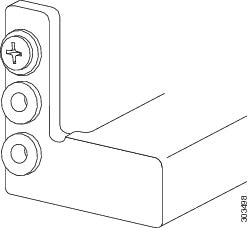
Attach two
doors to the hinge brackets (one per side). For each door:
Align the
door hinge hole with the bracket hinge hole (see the figure below).
Insert the
captive pin in the door hinge through the hole in the bracket hinge.
Note
You must
install the lower fan tray before attaching the accessory grill. The lower fan
tray slot is located behind the accessory grill. See
Installing Fan Trays, page 3-4
.
Figure 76.
Installing Optional Chassis Accessory Doors on the Cisco ASR 9010
Router
Step 9
Install the
front grill (item 8 in the
Step 4
by aligning and engaging it to the bottom two ball studs and pressing it in.
Installing Base
Chassis Accessories on the Cisco ASR 9006 Router
The base chassis
accessories for the Cisco ASR 9006 Router include:
One plastic fan tray door accessory piece
Two metal mounting brackets (left and right)
Two chassis side brackets (left and right)
Two plastic chassis corner pieces (left and right)
Two screws for attaching the plastic fan tray door accessory piece
Six screws for attaching the metal mounting brackets
If you did not
order the optional accessory set, follow these steps to install the supplied
base chassis accessories on the Cisco ASR 9006 Router.
Procedure
Step 1
Attach the
plastic accessory piece to the fan tray door using two supplied screws. Insert
the screws through the fan tray door from the inside of the door into the
accessory piece (see the figure below).
Step 2
Attach the left
metal mounting bracket to the front upper left corner of the chassis with three
screws.
Figure 77. Installing Plastic Fan Tray Door Accessory and Metal Mounting Brackets on the Cisco ASR 9006 Router
1
Plastic fan tray door accessory
2
Metal mounting bracket on left upper corner of chassis
3
Metal mounting bracket on right upper corner of chassis
Step 3
Attach the
right metal mounting bracket to the front upper right corner of the chassis
with three screws.
Step 4
Attach the left
and right side brackets to the chassis front edge on each side (see the figure
below). Attach each bracket to the chassis using three screws per bracket
inserted from the inside of the chassis, through the three chassis tabs into
the plastic brackets. Tighten the screws to a torque of 7 in-lb (0.80 N-m).
Figure 78. Installing
Chassis Side Brackets on the Cisco ASR 9010 Router
1
Left
chassis side bracket
2
Six
screws for attaching the chassis side brackets (three per side)
3
Right
chassis side bracket
Step 5
Attach the left
plastic corner piece to the mounting bracket at the front upper left corner of
the chassis (see the figure below).
Step 6
Attach the
right plastic corner piece to the mounting bracket at the front upper right
corner of the chassis.
Figure 79. Installing
Plastic Chassis Corners on the Cisco ASR 9006 Router (Base Accessories
Installation)
1
Plastic chassis corner piece attaches to metal bracket at upper left corner of
chassis
2
Plastic chassis corner piece attaches to metal bracket at upper right corner of
chassis
After the
chassis has been installed in the rack and all chassis accessories have been
attached, you can install the fan trays, power supply modules, and RSP and line
cards. See the chapter
Installing Cards and Modules in the Chassis in the
book
Cisco ASR 9000 Series Aggregation Services Router Hardware
Installation Guidefor detailed installation instructions.
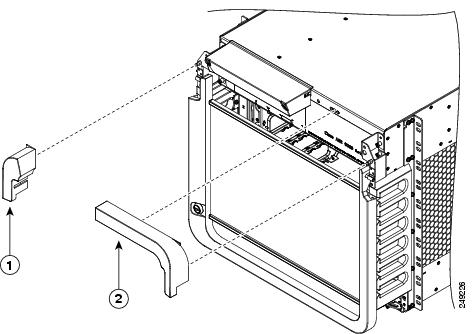
Installing Optional
Chassis Accessories on the Cisco ASR 9006 Router
The optional
chassis accessories for the Cisco ASR 9006 Router include:
Four ball stud assembly pieces (one set of two pieces per side)
One door with attached hinges
Four screws for assembling and attaching the ball stud assemblies
Assemble and
attach the two ball stud assemblies (see the figure below) to each chassis side
bracket. For each assembly:
Align the
two halves of the assembly to each other and to the screw holes in the chassis
side bracket.
Insert and
tighten two screws to secure the assembly to the side bracket.
Figure 80. Installing Ball Stud Assemblies on the Cisco ASR 9006 Router (Shown with Version 1 Power System)
Step 3
Attach the door
to the upper chassis panel (see the figure below) using two hex nuts per side
to secure the door hinges to the panel. Tighten the hex nuts to a torque of 4
in-lb (0.45 N-m).
Caution
Do not overtighten the hex nuts. They can be broken through overtightening.
Caution
When opening the door, be sure to grasp the center of the door to pull it open. Do not open the door by pulling on a corner
or side of the door frame.
Figure 81. Installing
the Optional Accessory Door on the Cisco ASR 9006 Router
Attach the
right plastic corner piece to the mounting bracket at the front upper right
corner of the chassis.
Figure 82. Installing
Plastic Chassis Corners on the Cisco ASR 9006 Router (Optional Accessories
Installation)
1
Plastic chassis corner piece attaches to metal bracket at upper left corner of
chassis
2
Plastic chassis corner piece attaches to metal bracket at upper right corner of
chassis
After the
chassis has been installed in the rack and all chassis accessories have been
attached, you can install the fan trays, power supply modules, and RSP and line
cards. See
Installing Cards and Modules in the Chassis in the
book
Cisco ASR 9000 Series Aggregation Services Router Hardware
Installation Guide for detailed installation instructions.
Installing Optional
Air Baffles on the Cisco ASR 9006 Router
The Cisco ASR 9006
Router has an optional air baffle accessory kit (800-43858-01) for mounting the
router chassis in a 2-post or 4-post 19-inch rack. The accessory kit includes:
One plenum with two pre-installed front rack-mounting brackets for attaching plenum to front side of rack-post
One support bracket
One plastic glide strip
Two rear rack-mounting brackets for attaching plenum to rear side of rack-post
Twelve 12-24 x 0.5 in. pan-head screws (six for attaching support bracket to chassis and six for securing chassis to rack-mounted
plenum)
Twelve 8-32 x 0.5 in. pan-head screws for attaching rear rack-mounting brackets on plenum
Air baffles allow
for front-to-back air flow through the chassis and help isolate exhaust air
from the intake air.
If you ordered the
optional air baffle accessory kit, follow these steps to install it:
Procedure
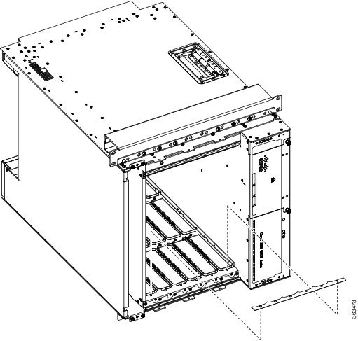
Step 1
Attach the
support bracket (part number: 800-43857-01) to the left side of the Cisco ASR
9006 Router using six 12-24 x 0.5 in. pan-head screws (part number:
48-0523-01). See the figure below.
Figure 83. Attaching
the Support Bracket to the Left Side of the Cisco ASR 9006 Router Chassis
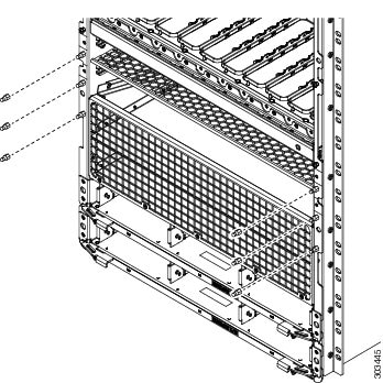
Step 2
Remove the
paper liner from the plastic guide strip and install on the right side of the
chassis card cage, as shown in the figure below.
Figure 84. Attaching
Plastic Glide Strip to Chassis
Step 3
Install the
plenum in the rack. Insert and tighten four customer-supplied screws to secure
the plenum to the front of the rack-post (two on each side). These screws can
vary in size and type depending on the rack that you use. Torque the screws to
the weight specified for your particular rack. See
Plenum
with Pre-Installed Front Mounting Brackets
and
Installing the Plenum in a Two-Post 19-Inch Rack.
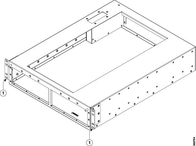
Figure 85. Plenum
with Pre-Installed Front Mounting Brackets
1
Front
rack-mounting bracket, pre-installed
Step 4
Attach the rear
rack-mounting brackets (part number: 700-47414-01) to the left and right sides
of the plenum base, using twelve 8-32 x 0.5 in. pan-head screws ((part number:
48-0828-01), six per bracket.
If you are installing the chassis in a four-post rack, rotate the rear rack-mounting brackets by 180 degrees and attach to
both sides of the plenum. The rear rack-mounting brackets secure the plenum to the rear rack-posts.
Step 5
Insert and
tighten four customer-supplied screws to secure the plenum to the rear of the
rack-post (two on each side). These screws can vary in size and type depending
on the rack that you use. Torque the screws to the weight specified for your
particular rack (see the figure below).
Figure 86. Installing the Plenum in a Two-Post 19-Inch Rack
1
Screw
attaching rear-rack mounting bracket to plenum (six per bracket)
3
Screws attaching rear-rack mounting bracket to rack (two per bracket)
Insert and
tighten four customer-supplied rack-mounting screws to secure the support
bracket on the chassis to the front of the rack-post (two on each side). These
screws can vary in size and type depending on the rack that you use. Torque the
screws to the weight specified for your particular rack (Securing
the ASR 9006 Router in a Two-Post 19-Inch Rack).
The figure
below shows the air baffle accessory kit and Cisco ASR 9006 Router with its
optional accessories fully installed in a two-post 19-inch rack.
Figure 88. Cisco ASR
9006 Router Fully Installed with Air Baffle Accessory Kit and Optional Chassis
Accessories
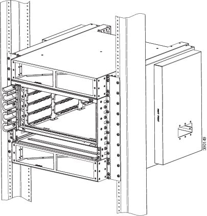
Installing Optional
Air Baffles on the Cisco ASR 9904 Router
The Cisco ASR 9904
Router has an optional air baffle accessory kit (ASR-9904-BAFFLE=) for mounting
the router chassis in a 2-post 23-inch rack. The accessory kit includes:
Two adapter plates
Two air baffles (left and right)
Two air deflectors
Twenty-eight 12-24 screws for attaching the air baffles and air deflectors to the adapter plate
Eight 8-32 screws for securing the side baffles to the air deflectors
Figure 89. Attaching
the Adapter Plates to the Left and Right Rack Rails on the Cisco ASR 9904
Router Chassis
Step 2
Loosely attach
the left and right side air baffles to the adapter plate (Installing
the Air Baffles on the Cisco ASR 9904 Router Chassis )
with 12-24 screws (four per side). Do not tighten these screws. To ensure the
correct orientation, “Left Front” and “Right Front” are stamped on each side of
the baffle.
Figure 90. Installing
the Air Baffles on the Cisco ASR 9904 Router Chassis
1
Right
side air baffle
3
12-24
screws for attaching the baffles (four per side)
Figure 94. Cisco ASR
9904 Router Chassis with Air Baffle in 2-Post 23-Inch Rack
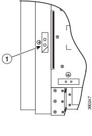
An electrical
conducting path must exist between the product chassis and the metal surface of
the enclosure or rack in which it is mounted, or to a grounding conductor. The
chassis has two grounding points on each side of the baffle, however only one
ground is required. The other will be grounded through the top and bottom air
deflectors.
Cisco ASR
9904 Router Baffle Ground
shows the baffle ground location on the chassis.
You can ground
the baffle by either attaching a grounding lug to the chassis (NEBS Supplemental Unit Bonding
and Grounding Guidelines, page 1-60
), or by using thread-forming mounting screws to establish a
metal-to-metal contact. If you are using screws, remove any paint or other
non-conductive coatings on the surfaces between the mounting hardware and the
enclosure or rack. Clean all surfaces and apply an antioxidant applied before
the installation.
Figure 95. Cisco ASR
9904 Router Baffle Ground
1
Baffle ground location
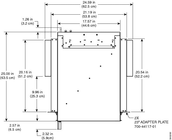
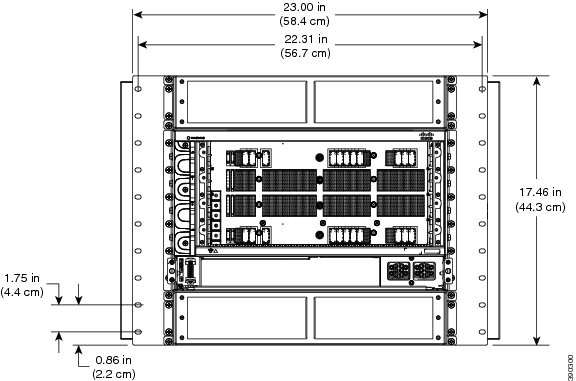
Figure 96. Cisco
ASR 9904 Router Air Baffle Dimensions—Top View
Figure 97. Cisco
ASR 9904 Router Air Baffle Dimensions—Front View
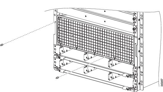
Installing Optional Chassis Accessories on the Cisco ASR 9906 Router
The optional chassis accessories for the Cisco ASR 9906 Router include:
Slide rails - A9K-SLIDE-RAIL
2-post rack mounting kit - ASR-9906-2P-KIT
4-post rack mounting kit - ASR-9906-4P-KIT
Installing Optional Chassis Accessories on the Cisco ASR 9910 Router
The optional chassis accessories for the Cisco ASR 9910 Router include:
Side guide rails
Rear air reflector
Installation brackets for 2-post and 4-post rack mounting
Installing Optional
Chassis Accessories on the Cisco ASR 9922 Router
The optional
chassis accessories for the Cisco ASR 9922 Router include:
Fan tray covers
Top and bottom card cage
front doors
Rear exhaust air deflector
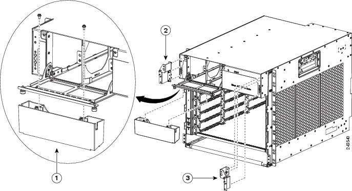
If you ordered the
optional accessories set, follow these steps to install the accessories:
Procedure
Step 1
Remove the two
screws that secure the bottom edge of the cable management tray to the chassis.
Note
Four ball
studs are preinstalled on the Cisco ASR 9922 Router chassis.
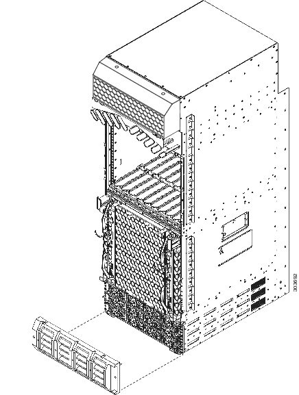
Figure 98. Optional
Fan Tray Covers for the Cisco ASR 9922 Router
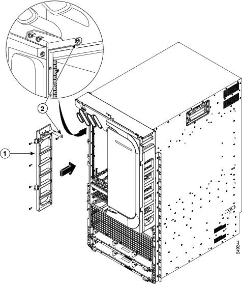
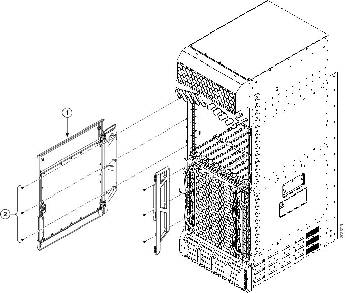
Figure 99. Optional
Card Cage Doors for the Cisco ASR 9922 Router
1
Card
cage door
2
Hinge
bracket
Step 2
Attach the left
and right hinge brackets to the chassis using three screws (M4 thread) for each
bracket. Tighten the screws to a torque of 11 in-lb (1.20 N-m). The L-shaped
brackets should align with the holes in the cable management tray from which
you removed the screws.
Step 3
Secure the
L-shaped brackets to the chassis and cable management tray by re-inserting and
tightening the cable management tray screws you removed.
Step 4
Align the
exhaust air deflector at the rear of the chassis behind the top fan tray
outlets (see the below figure), and use a screwdriver to tighten the two
screws, one on each side of the deflector. The deflector’s measurements are
width 17.48” x height 4.72” x depth 5.21” and deflects the outgoing exhaust
air.
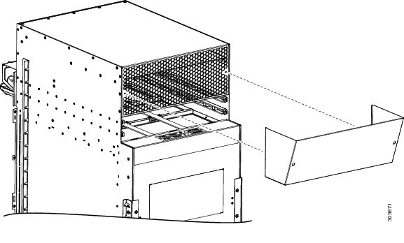
Figure 100. Optional
Rear Exhaust Air Deflector on the Cisco ASR 9922 Router
After the
chassis has been installed in the rack and all chassis accessories have been
attached, you can install the fan trays, power supply modules, RP cards, FCs
and LCs. See
Installing Cards and Modules in the Chassis in the
book
Cisco ASR 9000 Series Aggregation Services Router Hardware
Installation Guide for detailed installation instructions.
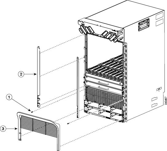
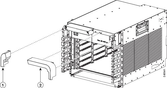
Installing Base
Chassis Accessories on the Cisco ASR 9912 Router
The base chassis
accessories for the Cisco ASR 9912 Router include (see the figure below):
One honeycomb cosmetic cover
One vented bezel to cover
the front of the power system
Procedure
Step 1
Attach the
honeycomb cosmetic cover to the front of the chassis above the cable management
bracket by aligning the cover above the screw tabs on the chassis.
Step 2
Attach the
vented bezel cover by snapping it into place in front of the power system.
Note
You will
need to remove the vented bezel cover in order to install the power system.
After the power system is installed, you can re-install the vented bezel cover.
Figure 101. Installing
Base Accessories on the Cisco ASR 9912 Router
After the
chassis has been installed in the rack and all chassis accessories have been
attached, you can install the fan trays, RP cards, FCs and LCs. See the chapter
Installing Cards and Modules in the Chassis in the
book
Cisco ASR 9000 Series Aggregation Services Router Hardware
Installation Guide for detailed installation instructions.
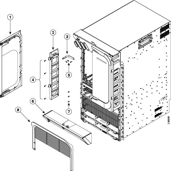
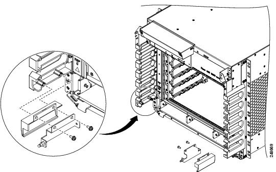
Installing Optional
Chassis Accessories on the Cisco ASR 9912 Router
The optional
chassis accessories for the Cisco ASR 9912 Router include:
Front door for the line card cage
Two hinge brackets (left and right side)
Six screws for attaching the hinge brackets to the chassis
Rear exhaust air deflector
If you ordered the
optional accessories set, follow these steps to install the accessories:
Procedure
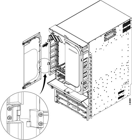
Step 1
Attach the left
(if not pre-installed) and right hinge brackets to the chassis using three
screws (M4 thread) for each bracket (see the below figure). Tighten the screws
to a torque of 11 in-lb (1.20 N-m).
Figure 102. Optional Card Cage Door on the Front of the Cisco ASR 9912 Router
1
Card cage door
2
Hinge bracket
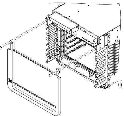
Step 2
Align the
exhaust air deflector at the top rear of the chassis above the fan trays (see
the below figure), and use a screwdriver to tighten the two screws, one on each
side of the deflector.
Figure 103. Optional
Rear Exhaust Air Deflector on the Cisco ASR 9912 Router
After the
chassis has been installed in the rack and all chassis accessories have been
attached, you can install the fan trays, RP cards, FCs, and LCs. See
Installing Cards and Modules in the Chassis in the
book
Cisco ASR 9000 Series Aggregation Services Router Hardware
Installation Guide for detailed installation instructions.


 Feedback