Prerequisites and Preparation
Before you perform any of the procedures in this chapter, be sure that you:
- Review the b-asr9k-hardware-installation-guide_chapter_01.html#con_1045496.
- Read the safety and ESD-prevention guidelines described in b-asr9k-hardware-installation-guide_chapter_01.html#con_1070848.
- Ensure that you have all the necessary tools and equipment before beginning the procedure.
Have access to the safety and compliance document during the installation, see:
http://www.cisco.com/en/US/docs/routers/asr9000/hardware/rcsi/regulatory/compliance/asr9krcsi.html
Field Replaceable Units
In the Cisco ASR 9006 Router, Cisco ASR 9010 Router, and Cisco ASR 9904 Router, the following components are field replaceable units (FRU):
-
All line cards
-
RSP cards
-
Power modules
-
Fan trays
-
Air filters
-
Line card and RSP blank fillers
-
Compact flash disk
-
Transceiver modules
-
Optional card cage doors (Cisco ASR 9010 Router only)
 Note |
The backplane is not field-replaceable. |
In the Cisco ASR 9906 Router, Cisco ASR 9910 Router, Cisco ASR 9912 Router, and Cisco ASR 9922 Router, the following components are FRUs:
-
All line cards
-
RP cards
-
RSP cards (only for Cisco ASR 9906 Router and Cisco ASR 9910 Router)
-
Fabric cards
-
Power modules
-
Fan trays and covers
-
Air filters
-
Foam media (only for Cisco ASR 9922 Router, Cisco ASR 9912 Router)
-
Blank line card fillers
-
Transceiver modules
-
Optional card cage doors
Note |
The backplane, midplane (only for Cisco ASR 9906 Router and Cisco ASR 9910 Router), PEM, and BPID cards are not FRUs but are field serviceable. |
Online Insertion and Removal
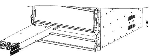
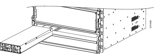
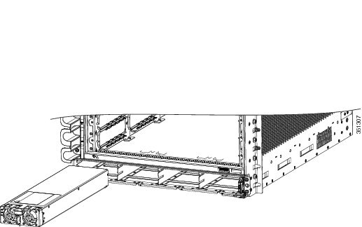
Most Cisco ASR 9000 Series Routers FRUs can be removed and replaced with the power on and the system operating. This is known as online insertion and removal (OIR). Power modules, fan trays, Route Switch Processor (RSP) cards, Route Processor (RP) cards, Fabric Controller (FC) cards, Line Cards (LCs), shared port adapter (SPA), and SPA interface processor (SIP) cards all support OIR. Unless otherwise noted, the maintenance tasks described in this chapter can be performed while the router remains powered on.
 Caution |
Never unplug all the fan trays at the same time. |
Note |
Although the power trays are not a true FRU because they do not support OIR, a procedure for replacing the power trays in Cisco ASR 9000 Series Routers is included in this chapter if a replacement becomes necessary. |
The following table displays the supported line cards, ports, and OIR duration for QDD-400G-ZR-S and QDD-400G-ZRP-S optical modules:
|
Line card |
Supported front panel ports |
Maximum supported OIR duration at mean sea level (MSL) with QDD-400G-ZR-S and QDD-400G-ZRP-S optical modules |
|---|---|---|
|
0, 7, 8, 12, 19 |
1 minute at 30°C (or 86°F) |
|
|
0, 7 |
3 minutes at 30°C (or 86°F) |
|
|
3, 5, 6, 7, 9 |
1 minute at 30°C (or 86°F) |
|
|
0, 4, 8, 12, 16 |
45 seconds at 30°C (or 86°F) |
OIR Monitoring
The BPID board monitors OIR by counting the number of card insertions for each slot and saving that information in non-volatile memory. OIR monitoring is done for all fan trays, RSP cards, RP cards, FCs, and LCs. A card insertion is determined by the CAN Bus Controller (CBC) of the inserted card booting up and sending a CBC message which is intercepted by the BPID board. Note that a CBC reset or power cycle on a card will also be interpreted as a card insertion.
Note |
A card with an OIR count that exceeds 175 will generate a minor alarm against that slot. If the card OIR count exceeds 200, a major alarm is generated against that slot. Fan tray insertion counts are not checked against a threshold. See the Release Notes for Cisco ASR 9000 Series Aggregation Services Routers for Cisco IOS XR Software Release 3.9.1 for information about CLI commands for obtaining and resetting card insertion data. |
Powering Off the Router
Caution |
Do not turn off the switch on the power tray to remove individual power modules. Power modules support OIR, so they can be removed and replaced with the power on and the system operating. |
If it becomes necessary to turn all power off to the router, follow these steps:
Procedure
|
Step 1 |
Set the power switch on each power tray to the off (0) position. |
|
Step 2 |
Power off all circuit breakers for the source power lines connected to the power trays. |
|
Step 3 |
Verify that the Pwr OK indicator on each power module is off. |
|
Step 4 |
Verify that the OK indicator on the fan tray is off. |
 Feedback