Preparing for Installation

This chapter provides preinstallation information, such as recommendations and requirements you should be perform before installing your Cisco ASR 9000 Series Router.

The shipping package for the router is engineered to reduce the chances of product damage associated with routine material handling experienced during shipment:

  • Always transport or store the router in its shipping package in the upright position.

  • Keep the router in the shipping container until you have determined the installation site.

Inspect all items for shipping damage. If an item appears damaged, contact a Cisco customer service representative immediately.

Safety Guidelines

Before you perform any procedure in this guide, you must review the safety guidelines in this section to avoid injuring yourself or damaging the equipment.

Note that this section contains guidelines and do not include every potentially hazardous situation. When you install a router, always use common sense and caution.

General Safety Guidelines

  • Never attempt to lift an object that might be too heavy for you to lift by yourself.

  • Always disconnect the power source and unplug all power cables before lifting, moving, or working on the router.

  • Keep the work area clear and dust free during and after the installation.

  • Keep tools and router components away from walkways and equipment rack aisles.

  • Do not wear loose clothing, jewelry (including rings and chains), or other items that could get caught in the router.

  • Fasten your tie or scarf and sleeves.

  • Operate Cisco equipment safely by using it in accordance with its electrical ratings and product usage instructions.

  • Do not work alone if potentially hazardous conditions exist.

  • Always unplug the power cables when performing maintenance or working on the router, unless the replacement part is hot swappable and designed for online insertion and removal (OIR).

  • Ensure that the installation of the router is in compliance with national and local electrical codes: in the United States, National Fire Protection Association (NFPA) 70, United States National Electrical Code; in Canada, Canadian Electrical Code, part I, CSA C22.1; in other countries, International Electrotechnical Commission (IEC) 364, part 1 through part 7.

Compliance and Safety Information

The Cisco ASR 9000 Series Routers are designed to meet the regulatory compliance and safety approval requirements. For detailed safety information, see the Regulatory Compliance and Safety Information - Cisco ASR 9000 Series Aggregation Router.


Warning


IMPORTANT SAFETY INSTRUCTIONS

Before you work on any equipment, be aware of the hazards involved with electrical circuitry and be familiar with standard practices for preventing accidents. Read the installation instructions before using, installing, or connecting the system to the power source. Use the statement number at the beginning of each warning statement to locate its translation in the translated safety warnings for this device.

SAVE THESE INSTRUCTIONS


Laser Safety

Single-mode Cisco ASR 9000 Series line cards are equipped with lasers. The lasers emit invisible radiation. Do not stare into open line card ports.

Energy Hazard

The Cisco ASR 9000 Series Routers can be configured for a DC power source. Do not touch terminals while they are live. Observe the following warning to prevent injury.


Warning


Hazardous voltage or energy may be present on power terminals. To reduce the risk of electric shock, make sure the power terminal cover is in place when the power terminal is not being serviced. Be sure uninsulated conductors are not accessible when the cover is in place.


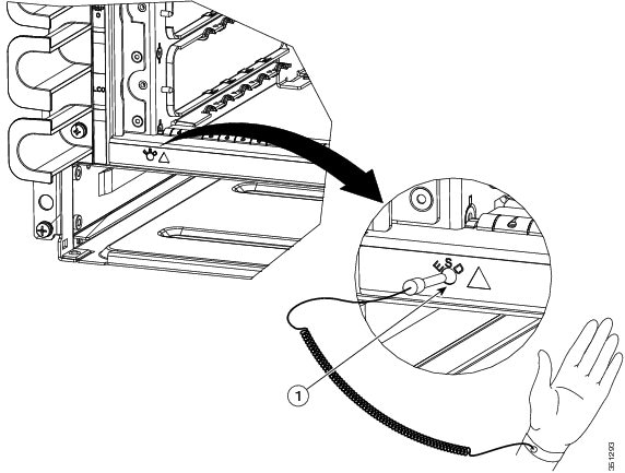
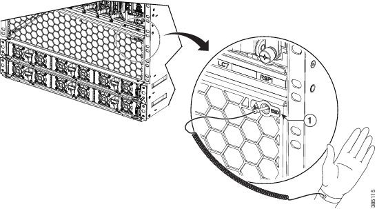
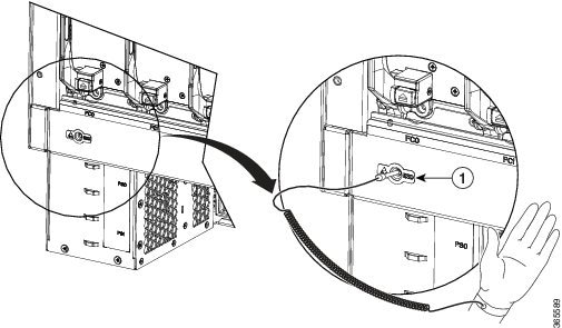
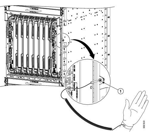
Preventing Electrostatic Discharge Damage

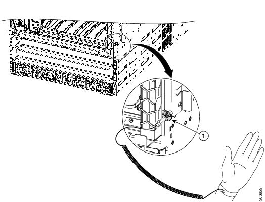
Many router components can be damaged by static electricity. Not exercising the proper electrostatic discharge (ESD) precautions can result in intermittent or complete component failures. To minimize the potential for ESD damage, always use an ESD-preventive antistatic wrist strap (or ankle strap) and ensure that it makes good skin contact.


Note


Check the resistance value of the ESD-preventive strap periodically. The measurement should be between 1 and 10 megohms.

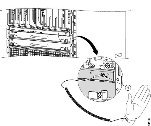
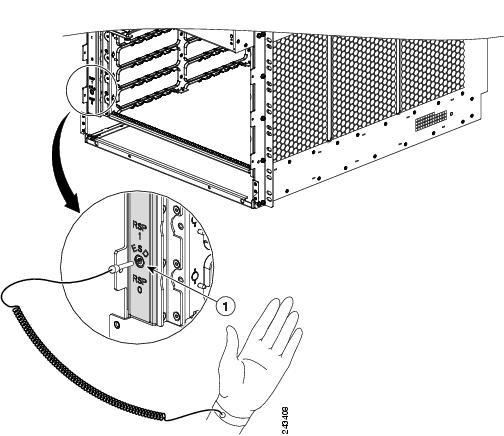
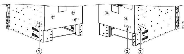
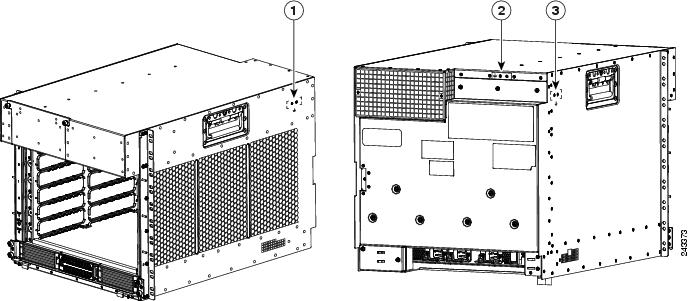
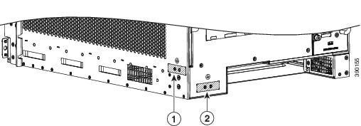
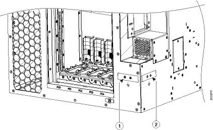
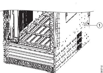
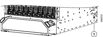
Before you perform any of the procedures in this guide, attach an ESD-preventive strap to your wrist and connect the leash to the chassis as shown in the figures below.

Figure 1. ESD Label Information on Router Chassis
Figure 2. ESD Label Information on Cisco ASR 9910 Router Chassis
Figure 3. Connecting an ESD-Preventive Wrist Strap to the Cisco ASR 9010 Router Chassis
Figure 4. Connecting an ESD-Preventive Wrist Strap to the Cisco ASR 9006 Router Chassis
Figure 5. Connecting an ESD-Preventive Wrist Strap to the Cisco ASR 9904 Router Chassis
Figure 6. Connecting an ESD-Preventive Wrist Strap to the Cisco ASR 9910 Router Chassis - Front
Figure 7. Connecting an ESD-Preventive Wrist Strap to the Cisco ASR 9910 Router Chassis - Rear
Figure 8. Connecting an ESD-Preventive Wrist Strap to the Cisco ASR 9922 Router Chassis
Figure 9. Connecting an ESD-Preventive Wrist Strap to the Cisco ASR 9912 Router Chassis

Lifting Guidelines

Fully configured Cisco ASR 9000 Series Routers can weigh as much as 1038 pounds (470.28 kg), and an empty chassis weighs up to 300 pounds (136 kg). These systems are not intended to be moved frequently. Before you install the router, ensure that your site is properly prepared to prevent moving the router later to accommodate power sources and network connections.

To move the pallet assembly, use a pallet jack or forklift. Do not top lift.

To remove the unpacked chassis from the pallet base and to insert the chassis into the rack, we strongly recommend that you use a forklift or scissor-lift, supporting the chassis by the base only.

If you are moving a smaller chassis, use the following lifting guidelines to avoid injury to yourself or damage to the equipment:

  • Do not lift equipment alone; have another person help you to lift heavy equipment.

  • Ensure that your footing is solid; balance the weight of the object between your feet.

  • Lift the equipment slowly; never move suddenly or twist your body as you lift.

  • Keep your back straight and lift with your legs, not your back. When bending down to lift equipment, bend at the knees (not at the waist), to reduce the strain on your lower back muscles.


Warning


To prevent injury and equipment damage, never attempt to lift or tilt the router chassis using the handles on the fan tray or on line cards. These handles do not support the weight of the chassis.

Cautions and Regulatory Compliance Statements for NEBS

The following are NEBS GR-1089-CORE cautions, regulatory compliance statements, and requirements:


Warning


The intrabuilding port(s) of the equipment or subassembly must use shielded intrabuilding cabling/wiring that is grounded at both ends.

The following port(s) are considered intrabuilding ports on this equipment:


Warning


The intrabuilding port(s) of the equipment or subassembly is suitable for connection to intrabuilding or unexposed wiring or cabling only. The intrabuilding port(s) of the equipment or subassembly MUST NOT be metallically connected to interfaces that connect to the OSP or its wiring for more than 6 meters (approximately 20 feet). These interfaces are designed for use as intrabuilding interfaces only (Type 2, 4, or 4a ports as described in GR-1089) and require isolation from the exposed OSP cabling. The addition of primary protectors is not sufficient protection in order to connect these interfaces metallically to an OSP wiring system.

The following ports are considered intrabuilding ports on the equipment:


Warning


Connect this equipment to AC mains that are provided with a surge protective device (SPD) at the service equipment that complies with NFPA 70, the National Electrical Code (NEC).


Note


This equipment is suitable for installations using the CBN.


Note


Treat the battery return conductor of this equipment as


Note


This equipment is suitable for installation in network telecommunications facilities.


Note


This equipment is suitable for installation in locations where the NEC applies.


Note


This equipment is designed to boot up in less than 30 minutes, depending on its neighboring devices that must be fully up and running.

Site Requirement Guidelines

The following sections contain the site requirement guidelines that you should be familiar with before installing the router:

Site Layout and Equipment Dimensions


Note


Refer to the Rack-Mounting Specifications section in the Cisco ASR 9000 Series Aggregation Services Router Overview and Reference Guide for rack mounting specifications and chassis dimensions.

To help maintain trouble-free operation, adhere to the following precautions and guidelines when planning your rack installation:

  • Install the system in a restrictive access location with means for a permanent ground.

  • Ensure the site of the rack includes provisions for source AC or DC power, grounding, and network interface cables.

  • Allow sufficient space to work around the rack during the installation. You need:

    • At least 3 ft (91.44 cm) adjacent to the rack to move, align, and insert the chassis.

    • At least 2 ft (60.96 cm) in front of the power tray to insert power modules.

  • Maintain at least 24 inches (61 cm) of clearance in front of and behind the chassis for maintenance after installation.


    Note


    • For the Cisco ASR 9910 Router, maintain at least 30 inches (76.2 cm) of clearance behind the chassis for maintenance after installation (for removal and installation of the rear-mounted fan tray).

    • For the Cisco ASR 9904 Router, maintain at least 26 inches (66.0 cm) of clearance behind the chassis for maintenance after installation (for removal and installation of the rear-mounted fan tray and air filter).

    • For the Cisco ASR 9006 Router, maintain at least 25 inches (63.5 cm) of clearance behind the chassis for maintenance after installation (for removal and installation of the rear-mounted air filter).


  • To mount the router between two posts or rails, the usable aperture (the width between the inner edges of the two mounting flanges) must be at least:

    • 17.50 inches (44.45 cm) for the Cisco ASR 9010 Router.

    • 17.75 inches (45.09 cm) for the Cisco ASR 9006 Router, Cisco ASR 9904 Router, and Cisco ASR 9906 Router.

    • 17.60 inches (44.70 cm) for the Cisco ASR 9910 Router.

  • To mount the router in a 4-post rack, the usable aperture (the width between the inner edges of the two mounting flanges) must be at least 17.75 inches (45.09 cm) for the Cisco ASR 9922 Router or Cisco ASR 9912 Router.

  • When fully populated with cards, the router can weigh up to 1038 pounds (470.28 kg). To maintain equipment rack stability and to ensure your safety, the rack is provided with stabilizing devices. Make sure you install the stabilizers before installing the router.

  • If you use a telco-style rack, the weight of the chassis is cantilevered off of the two rack posts. Make sure that:

    • Weight of the router does not make the frame unstable.

    • Frame is bolted to the floor and is secured to the building structure using either wall brackets or overhead brackets.

  • When mounting the router in a telco-style rack or 4-post rack, be sure to use all of the screws provided to secure the chassis to the rack posts.

  • Install the cable-management brackets included with the router to keep cables organized. Be sure to:

    • Use appropriate strain-relief methods to protect cables and equipment connections.

    • Make sure that cables from other equipment installed in the rack do not restrict access to the card cages.

  • To avoid noise interference in network interface cables, do not route them directly across or along power cables.

Site Wiring Guidelines

When planning the location of the router, consider distance limitations for signaling, electromagnetic interference (EMI), and connector compatibility. If the wiring is run for any significant distance in an electromagnetic field, interference can occur between the field and the signals on the wires. Poor wiring can cause:

  • Radio interference emanating from the wires.
  • Strong EMI, especially when caused by lightning or radio transmitters. EMI can destroy the signal drivers and receivers in the router, and can even create an electrical hazard by conducting power surges through lines and into equipment.

Note


To predict and remedy strong EMI, you may need to consult with experts in radio frequency interference (RFI).

Site wiring is unlikely to emit radio interference if you use twisted-pair cable with a good distribution of grounding conductors. Use a high-quality twisted-pair cable with one ground conductor for each data signal, when applicable.

Give special consideration to the effect of a lightning strike in your vicinity, especially if the wiring exceeds the recommended distances, or if it passes between buildings. The electromagnetic pulse (EMP) caused by lightning or other high-energy phenomena can easily induce enough energy into unshielded conductors to destroy electronic devices. If you have experienced EMP problems in the past, you may want to consult experts in electrical surge suppression and shielding.

Most data centers cannot resolve infrequent but potentially catastrophic problems without pulse meters and other special equipment. In addition, these problems can take a great deal of time to identify and resolve. We recommend that you take the necessary precautions to avoid these problems by providing a properly grounded and shielded environment, with special attention to issues of electrical surge suppression.

Chassis Air Flow Guidelines

Refer to the Cooling System Functional Description section in the Cisco ASR 9000 Series Aggregation Services Router Overview and Reference Guide for information on fan tray and chassis air flow information.

When selecting a site to install the router, observe the following guidelines:

  • Dust-free area—The site should be as dust-free as possible. Dusty environments can clog the air filter or power supply intake vents, reducing the cooling air flow through the router. Clogged filters and vents can cause an overtemperature condition in the router.

  • Unrestricted air-flow—Allow sufficient air-flow by maintaining a minimum of 6 in (15.24 cm) of clearance at both the inlet and exhaust openings on the chassis and the power modules. If the air flow is blocked or restricted, or if the inlet air is too warm, an overtemperature condition can occur within the router. Under extreme conditions, the environmental monitoring system powers off the router to protect the components.

Rack-Mounting and Air Flow Clearance Guidelines

The Cisco ASR 9010 Router, Cisco ASR 9006 Router, Cisco ASR 9904 Router, Cisco ASR 9906 Router, and Cisco ASR 9910 Router can be installed in most 2-post, 4-post, or telco-style 19-inch equipment racks that comply with the Electronics Industries Association (EIA) standard for equipment racks (EIA-310-D).


Note


The Cisco ASR 9922 Router and Cisco ASR 9912 Router can be mounted only in a 4-post rack. The rack must have at least two posts with mounting flanges to mount the router chassis. The distance between the center lines of the mounting holes on the two mounting posts must be 18.31 inches ± 0.06 inch (46.50 cm ± 0.15 cm).

This figure shows an examples of typical 2-post and 4-post telco-type equipment racks.

Figure 10. Telco-Type Equipment Racks

a

Telco-style rack

b

Free-standing, 4-post open rack with two mounting posts in the front, two mounting posts in the back or along each side.

c

Free-standing enclosed rack with perforated sides and two mounting posts in the front.

Telco 2-Post Rack

Item a in Telco-Type Equipment Racks shows a telco-style rack. The telco-style rack is an open frame consisting of two posts tied together by a cross-bar at the top and a floor stand at the bottom.

This type of rack is usually secured to the floor and sometimes to an overhead structure or wall for additional stability. The router chassis can be installed in the telco-style rack only in a front-mounted position.

In the front-mounted position, you secure the chassis rack-mounting brackets directly to the rack posts (see below figures). Two rear mounting brackets are provided for mounting the Cisco ASR 9010 Router in a 2-post rack.

Use 2 post rack-mounting brackets and associated hardware to secure rear mounting bracket to sides of chassis and back of 2 post rack.


Note


The mounting brackets on the Cisco ASR 9006 Router chassis have a pair of holes at the top and bottom of each bracket; the remaining openings in the brackets are slots. When mounting the router in a 2-post rack, you must first use the holes to locate and position the brackets on the rack. Insert the screws through the bracket holes into the rack before inserting screws through the bracket slots.
Figure 11. Cisco ASR 9010 Router Mounted in a 2-Post Rack
Figure 12. Cisco ASR 9006 Router Mounted in a 2-Post Rack
Figure 13. Cisco ASR 9904 Router Mounted in a 2-Post Rack
Figure 14. Cisco ASR 9906 Router Mounted in a Seismic 2-Post Rack
Figure 15. Cisco ASR 9906 Router Mounted in a Standard 2-Post Rack
Figure 16. Cisco ASR 9910 Router Mounted in a 2-Post Rack

Open 4-Post Rack

Item b in Telco-Type Equipment Racks shows a free-standing, 4-post open rack with two mounting posts in the front and two mounting posts in the back or along the side. The mounting posts in this type of rack are often adjustable so that you can position the rack-mounted unit within the depth of the rack rather than flush-mount it with the front of the rack.

  • Two rear mounting brackets are provided for mounting the Cisco ASR 9906 Router and Cisco ASR 9010 Router in a 4-post rack.

  • Two rear mounting brackets and two bottom guide rails are provided for mounting the Cisco ASR 9922 Router and Cisco ASR 9912 Router in a 4-post rack.

  • Rear brackets are not provided for mounting the Cisco ASR 9904 Router in a 4-post rack.

Figure 17. Cisco ASR 9906 Router Side View showing vertical Rack Rail Locations.
Figure 18. Mounting the Cisco ASR 9906 Router in an Open 4-Post Rack -Left View
Figure 19. Mounting the Cisco ASR 9906 Router in an Open 4-Post Rack -Right View
Figure 20. Mounting the Cisco ASR 9910 Router in an Open 4-Post Rack
Figure 21. Mounting the Cisco ASR 9912 Router in an Open 4-Post Rack
Figure 22. Mounting the Cisco ASR 9922 Router in an Open 4-Post Rack

4-Post Enclosed Rack with Perforated Sides

Item c in Telco-Type Equipment Racks shows a free-standing 4-post enclosed rack with perforated sides and two mounting posts in the front.


Caution


Do not install the Cisco ASR 9000 Series Router in any type of fully enclosed rack that does not have the required perforated sides or doors; the router requires an unobstructed flow of cooling air to maintain acceptable operating temperatures for its internal components. Installing the router in any type of fully enclosed rack without proper perforation could disrupt the air-flow, trap heat next to the chassis, and cause an overtemperature condition inside the router.

Air Flow Guidelines for Enclosed Rack Installation

Follow these guidelines when installing the Cisco ASR 9000 Series Routers in a 4-post enclosed rack.

Cisco ASR 9006 Clearance Requirements

To install a Cisco ASR 9006 Router in a 4-post enclosed cabinet:

  • The front and rear doors of the cabinet must be removed or be perforated with a minimum open area of 70 percent. In addition, the right side panel must be removed or perforated with a minimum of 65 percent open area (70 percent for 800-mm racks).

  • There must be a minimum unobstructed space of 6 inches (15.24 cm) between the router’s right side air inlet and the adjacent wall or cabinet side panel, and a minimum unobstructed space of 6 inches (15.24 cm) between adjacent cabinets. In addition, there should be no exhaust from any source blowing into the right side panel of the cabinet.

    • Rear chassis clearance: Minimum of 2.50 inches (6.40 cm) of clearance.

    • Sides chassis clearance: Minimum of 6 inches (15.24 cm) of clearance on the right side of the chassis (as viewed from the front). There is no clearance requirement for the left side of the chassis.

This figure shows the side and rear chassis air-flow clearance requirements for mounting the Cisco ASR 9006 Router in a 4-post enclosed rack.

Figure 23. Cisco ASR 9006 Router Clearance Requirements for an Enclosed 4-Post Rack Installation

Cisco ASR 9010 Router Clearance Requirements

To install a Cisco ASR 9010 Router in a 4-post enclosed cabinet:

  • The front and rear doors of the cabinet must be removed or be perforated with a minimum open area of 65 percent (70 percent for 800-mm racks).

  • Ensure that you have the following clearances around the chassis:

    • Rear: Minimum of 3.15 inches (8.00 cm) of clearance.

    • Sides: Minimum of 2.87 inches (7.28 cm) of clearance on each side of the chassis.

This figure shows the side and rear chassis air-flow clearance requirements for mounting the Cisco ASR 9010 Router in a 4-post enclosed rack.

Figure 24. Cisco ASR 9010 Router Clearance Requirements for an Enclosed 4-Post Rack Installation

Cisco ASR 9904 Clearance Requirements

To install the Cisco ASR 9904 Router in a 4-post enclosed cabinet:

  • Ensure that you have the following clearances around the chassis:

    • Rear: Minimum of 2.45 inches (6.22 cm) of clearance.

    • Sides: Minimum of 6.00 inches (15.24 cm) of clearance on each side of the chassis.

This figure shows the side and rear chassis air-flow clearance requirements for mounting the Cisco ASR 9904 Router in a 4-post enclosed rack.

Figure 25. Cisco ASR 9904 Router Clearance Requirements in a 4-Post Rack Installation

Cisco ASR 9906 Router Clearance Requirements

To install the Cisco ASR 9906 Router in a 4-post enclosed cabinet:

  • The front and rear doors of the cabinet must be removed or be perforated with a minimum open area of 65 percent (70 percent for 800-mm racks).

  • Ensure that you have the following clearances around the chassis:

    • Rear and front: Minimum of 6.00 inches (15.24 cm) of clearance.

    • Sides: Minimum of 2.95 inches (7.49 cm) of clearance on each side of the chassis.

This figure shows the side, front, and rear chassis air-flow clearance requirements for mounting the Cisco ASR 9906 Router in a 4-post enclosed rack.

Figure 26. Cisco ASR 9906 Router Clearance Requirements in a 4-Post Rack Installation

Cisco ASR 9910 Router Clearance Requirements

To install the Cisco ASR 9910 in a 4-post enclosed cabinet:

  • The front and rear doors of the cabinet must be removed or be perforated with a minimum open area of 70 percent open area (80 percent for 800-mm racks).

  • Ensure that you have the following clearances around the chassis:

    • Rear: Minimum of 6 inches (15.24 cm) of clearance.

    • Sides: Minimum of 2.87 inches (7.28 cm) of clearance on each side of the chassis.

This figure shows the side and rear chassis air-flow clearance requirements for mounting the router in a 4-post enclosed rack.

Cisco ASR 9912 Clearance Requirements

To install the Cisco ASR 9912 Router in a 4-post enclosed cabinet:

  • The front and rear doors of the cabinet must be removed or be perforated with a minimum open area of 70 percent open area (80 percent for 800-mm racks)

    .
  • Ensure that you have the following clearances around the chassis:

    • Rear: Minimum of 10 inches (25.4 cm) of clearance.

    • Sides: Minimum of 2.87 inches (7.28 cm) of clearance on each side of the chassis.

This figure shows the side and rear chassis air-flow clearance requirements for mounting the router in a 4-post enclosed rack.

Figure 27. Cisco ASR 9912 Router Clearance Requirements in a 4-Post Rack Installation

Cisco ASR 9922 Clearance Requirements

To install the Cisco ASR 9922 Router in a 4-post enclosed cabinet:

  • The front and rear doors of the cabinet must be removed or be perforated with a minimum open area of 70 percent (80 percent for 800-mm racks).

  • Ensure that you have the following clearances around the chassis:

    • Rear: Minimum of 10 inches (25.4 cm) of clearance.

    • Sides: Minimum of 2.87 inches (7.28 cm) clearance on each side of the chassis.

This figure shows the clearance requirements for mounting the Cisco ASR 9922 Router in a 4-post enclosed rack.

Figure 28. Cisco ASR 9922 Router Clearance Requirements in a 4-Post Rack Installation

Temperature and Humidity Guidelines

The operating and nonoperating environmental site requirements are listed in Cisco ASR 9000 Series Routers Environmental Specifications section of Cisco ASR 9000 Series Aggregation Services Router Overview and Reference Guide.

The router normally operates within the ranges listed in the table; however, if a temperature measurement is approaching a minimum or maximum parameter, it indicates a potential problem. Maintain normal operation by anticipating and correcting environmental anomalies before they approach critical values by properly planning and preparing your site before you install the router.

Power Connection Guidelines

You can configure the router with either an AC input or DC input power subsystem, so the site power source requirements differ depending on the power subsystem in your router. Ensure all power connection wiring conforms to the rules and regulations in the National Electrical Code (NEC) as well as local codes.


Caution


Each Cisco ASR 9000 Series Router is powered by only one type of input: AC or DC. A hybrid (AC+DC) power configuration is not supported.
Table 1. Cisco ASR 9000 Series Routers Supported Power Systems

Router

Supported Power Systems

Cisco ASR 9006

Version 1: Supports up to three power modules in the power tray.

Version 2: Supports up to four power modules in the power tray Compatible only with Cisco IOS XR Software Release 4 and later Cisco IOS XR software releases.

Version 3: Compatible only with Cisco IOS XR Software Release 6.5.3 and later Cisco IOS XR software releases.

Cisco ASR 9010

Version 1: Supports up to three power modules in the power tray.

Version 2: Supports up to four power modules in the power tray Compatible only with Cisco IOS XR Software Release 4 and later Cisco IOS XR software releases.

Version 3: Supports up to four DC power modules in the DC power tray and up to three AC power modules in the AC power tray. Compatible only with Cisco IOS XR Software Release 5.3.0 and later Cisco IOS XR software releases.

Cisco ASR 9904

Version 2: Supports up to four power modules in the power tray. Compatible only with Cisco IOS XR Software Release 4 and later Cisco IOS XR software releases.

Version 3: Compatible only with Cisco IOS XR Software Release 6.5.3 and later Cisco IOS XR software releases.

Cisco ASR 9906

Version 3: Supports up to three AC power modules in the AC power tray and up to four DC power modules in the DC power tray.

Cisco ASR 9910

Version 3: Supports up to three AC power modules in the AC power tray and up to four DC power modules in the DC power tray.

Cisco ASR 9912

Cisco ASR 9922

Version 2: Supports up to four power modules in the power tray.

Version 3: Supports up to four DC power modules in the DC power tray and up to three AC power modules in the AC power tray. Compatible only with Cisco IOS XR Software Release 5.3.0 and later Cisco IOS XR software releases.


Caution


Proper grounding is necessary to avoid damage from lightning and power surges. See NEBS Supplemental Unit Bonding and Grounding Guidelines for grounding requirements.

AC-Powered Routers

AC power modules operate in the input range of 180 VAC to 264 VAC, 47 to 63 Hz (nominal input level of 200 to 240 VAC). Refer the below tables for the minimum required AC service for version 1 and version 2 power modules.

Power redundancy requirements vary based on the system configuration (number and type of line cards, etc.). AC-powered systems are 2N protected. A minimum of two power supplies are required for redundant operation.

Each of the AC power inputs requires a separate dedicated branch circuit. Note that the circuit breaker and fuse lockout procedures should follow the rules and regulations in the National Electrical Code (NEC) and any local codes. For a list of the nominal and acceptable value ranges for source AC power, see Cisco ASR 9000 Series Routers AC Electrical Specifications section of Cisco ASR 9000 Series Aggregation Services Router Overview and Reference Guide.

This table lists the AC input power cord options, specifications, and Cisco product numbers for the AC input version 1 power supply modules. lists the AC input power cord options, specifications, and Cisco product numbers for the AC input version 2 power and version 3 supply modules.


Note


Before connecting AC input power cords to the power system, make sure that the power cords are not energized.
Table 2. AC Input Power Cord Options for Version 1 Power System

Locale

Part Number

Length

Plug Rating

Power Cord Reference Illustration

Australia, New Zealand

CAB-7513ACA=

14 ft (4.3 m)

15 A, 250 VAC

AC Power Cord CAB-7513ACA=

Australia, New Zealand

CAB-AC-16A-AUS=

14 ft (4.3 m)

16A, 250 VAC

AC Power Cord CAB-AC-16A-AUS

China

CAB-AC16A-CH=

14 ft (4.3 m)

16 A, 250 VAC

AC Power Cord CAB-AC16A-CH=

Continental Europe

CAB-7513ACE=

CAB-2500W-EU=

CAB-AC-2500W-EU=

14 ft (4.3 m)

16 A, 250 VAC

16 A, 250 VAC

16 A, 250 VAC

AC Power Cord CAB-7513ACE=

AC Power Cord CAB-2500W-EU=

AC Power Cord CAB-AC-2500W-EU=

International

CAB-AC-2500W-INT=

14 ft (4.3 m)

16 A, 250 VAC

AC Power Cord CAB-AC-2500W-INT=

Israel

CAB-AC-2500W-ISRL=

14 ft (4.3 m)

16 A, 250 VAC

AC Power Cord CAB-AC-2500W-ISRL=

Italy

CAB-7513ACI=

14 ft (4.3 m)

16 A, 250 VAC

AC Power Cord CAB-7513ACI=

Japan, North America (nonlocking plug) 200–240VAC operation

CAB-AC-2500W-US1=

14 ft (4.3 m)

20 A, 250 VAC

AC Power Cord CAB-AC-2500W-US1=

Japan, North America (locking plug) 200–240VAC operation

CAB-AC-C6K-TWLK=

14 ft (4.3 m)

20 A, 250 VAC

AC Power Cord CAB-AC-C6K-TWLK=

South Africa

CAB-7513ACSA=

14 ft (4.3 m)

16 A, 250 VAC

AC Power Cord CAB-7513ACSA=

Switzerland

CAB-ACS-16=

14 ft (4.3 m)

16 A, 250 VAC

AC Power Cord CAB-ACS-16=

Table 3. AC Input Power Cord Options for Version 2 and Version 3 Power System

Locale

Part Number

Length

Plug Rating

Reference Illustration

China

PWR-CAB-AC-CHN=

13.9 ft (4.3 m)

16 A, 250 V

AC Power Cord PWR-CAB-AC-CHN=

Europe

PWR-CAB-AC-EU=

13.9 ft (4.3 m)

16 A, 250 V

AC Power Cord PWR-CAB-AC-EU=

Israel

PWR-CAB-AC-ISRL=

13.9 ft (4.3 m)

16 A, 250 V

AC Power Cord PWR-CAB-AC-ISRL=

USA

PWR-CAB-AC-USA=

13.9 ft (4.3 m)

20 A, 250 V

AC Power Cord PWR-CAB-AC-USA=

Australia

PWR-CAB-AC-AUS=

13.9 ft (4.3 m)

16 A, 250 V

AC Power Cord PWR-CAB-AC-AUS=

Italy

PWR-CAB-AC-ITA=

13.9 ft (4.3 m)

16 A, 250 V

AC Power Cord PWR-CAB-AC-ITA=

Brazil

PWR-CAB-AC-BRA=

13.9 ft (4.3 m)

16 A, 250 V

AC Power Cord PWR-CAB-AC-BRA=

South Africa

PWR-CAB-AC-SA=

13.9 ft (4.3 m)

16 A, 250 V

AC Power Cord PWR-CAB-AC-SA=

UK

PWR-CAB-AC-UK=

13.9 ft (4.3 m)

16 A, 250 V

AC Power Cord PWR-CAB-AC-UK=

Switzerland

PWR-CAB-AC-SUI=

13.9 ft (4.3 m)

16 A, 250 V

AC Power Cord PWR-CAB-AC-SUI=

Japan

PWR-CAB-AC-JPN=

13.9 ft (4.3 m)

20 A, 250 V

AC Power Cord PWR-CAB-AC-JPN=

AC Power Cord Illustrations (Version 1 Power)

This section contains the AC power cord illustrations for version 1 power, as described in Table 1. Note that an AC power cord may be used with several power supplies.

Figure 29. AC Power Cord CAB-7513ACA=
Figure 30. AC Power Cord CAB-AC-16A-AUS
Figure 31. AC Power Cord CAB-AC16A-CH=
Figure 32. AC Power Cord CAB-7513ACE=
Figure 33. AC Power Cord CAB-2500W-EU=
Figure 34. AC Power Cord CAB-AC-2500W-EU=
Figure 35. AC Power Cord CAB-AC-2500W-INT=
Figure 36. AC Power Cord CAB-AC-2500W-ISRL=
Figure 37. AC Power Cord CAB-7513ACI=
Figure 38. AC Power Cord CAB-AC-2500W-US1=
Figure 39. AC Power Cord CAB-AC-C6K-TWLK=
Figure 40. AC Power Cord CAB-7513ACSA=
Figure 41. AC Power Cord CAB-ACS-16=

AC Power Cord Illustrations (Version 2 and Version 3 Power)

This section contains the AC power cord illustrations for version 2 power, as described in Table 2.

Figure 42. AC Power Cord PWR-CAB-AC-CHN=
Figure 43. AC Power Cord PWR-CAB-AC-EU=
Figure 44. AC Power Cord PWR-CAB-AC-ISRL=
Figure 45. AC Power Cord PWR-CAB-AC-USA=
Figure 46. AC Power Cord PWR-CAB-AC-AUS=
Figure 47. AC Power Cord PWR-CAB-AC-ITA=
Figure 48. AC Power Cord PWR-CAB-AC-BRA=
Figure 49. AC Power Cord PWR-CAB-AC-SA=
Figure 50. AC Power Cord PWR-CAB-AC-UK=
Figure 51. AC Power Cord PWR-CAB-AC-SUI=
Figure 52. AC Power Cord PWR-CAB-AC-JPN=

DC-Powered Router

Connections to DC power modules are rated at 60 A maximum. The system accepts a nominal input voltage of –48 VDC with an operational tolerance range of –40 VDC to –72 VDC. One dedicated, commensurately rated DC power source is required for each power module connection.

Power redundancy requirements vary based on the system configuration (number and type of line cards, etc.). DC-powered systems are N+1 protected. A minimum of two power supplies are required for redundant operation.

Power connections to the power tray for each DC power module requires four cables: two source cables and two return cables. In addition, each DC power tray requires one earth ground, so the minimum number of cables for connecting a single DC power module in a power tray is five (two source, two return, one ground).


Note


A separate ground connection is not required for the version 2 and version 3 power systems. For more information see NEBS Supplemental Unit Bonding and Grounding Guidelines.

For DC power cables, we recommend that you use 60-A-rated, high-strand-count copper wire cables. The length of the cables depends on your router location from the source power. DC power cables are not available from Cisco, but they are available from any commercial cable vendor.

You must terminate DC power cables using cable lugs at the power tray end. Ensure that the lugs are dual-hole and that they fit over M6 terminal studs at 0.625-inch (15.88-mm) centers. For #4 AWG cable, use Panduit part number LCD4-14AF-L or equivalent; for #6 AWG, use Panduit part number LCD6-14AF-L or equivalent.


Warning


Hazardous voltage or energy may be present on power terminals. To reduce the risk of electric shock, make sure the power terminal cover is in place when the power terminal is not being serviced. Be sure uninsulated conductors are not accessible when the cover is in place.


Note


Before connecting DC power cords to the power system, make sure that the input power cords are not energized.

Note


Ensure that there is a readily accessible disconnect device incorporated in the building’s installation wiring.

Note


Circuit breaker and fuse lockout procedures should follow the rules and regulations in the National Electrical Code (NEC) and any local codes.

This figure shows the lug type required for DC input cable connections.

Figure 53. Typical DC Power Cable Lug

Note


The DC power trays and power modules for the Cisco ASR 9000 Series Routers are identical, so the examples shown in the below figures apply to all of these routers.

Warning


To avoid shock hazard, be sure to apply shrink wrap tubing around the wire entry area of the lug.
Figure 54. Typical Source DC Power Cabling Scheme for a Single DC Power Module—Version 1 Power System
Figure 55. Typical Source DC Power Cabling Scheme for a Single DC Power Module—Version 2 Power System
Figure 56. Typical Plastic Safety Cover over the Power Tray Connection Terminals—Version 2 and Version 3 Power System
Figure 57. Typical Source DC Power Cabling Scheme for a Single DC Power Module—Version 3 Power System

Note


A separate ground connection is not required for the version 2 or version 3 power systems. For more information see the NEBS Supplemental Unit Bonding and Grounding Guidelines.

The color coding of source DC power cable leads depends on the color coding of the site DC power source. Because there is no color code standard for source DC wiring, be sure that power source cables are connected to the power modules using the proper positive (+) and negative (–) polarity:

  • In some cases, the source DC cable leads might have a positive (+) or a negative (–) label. This is a relatively safe indication of the polarity, but you must verify the polarity by measuring the voltage between the DC cable leads . Be sure that the positive (+) and negative (–) cable leads match the positive (+) and negative (–) labels on the power module when making the measurement.

  • Green (or green and yellow) cable typically indicates that it is a ground cable.


Caution


DC power modules contain reverse voltage protection circuitry to prevent damage to the power module if it detects a reverse polarity condition. No damage should occur from reverse polarity, but you should correct a reverse polarity condition immediately.

For a list of the nominal and acceptable value ranges for source DC power, see Technical Specifications chapter from Cisco ASR 9000 Series Aggregation Services Router Overview and Reference Guide

NEBS Supplemental Unit Bonding and Grounding Guidelines

The router is sensitive to variations in voltage supplied by the power sources. Overvoltage, undervoltage, and transients (or spikes) can erase data from memory or cause components to fail. To protect against these types of problems, ensure that there is an earth-ground connection for the router. You can connect the grounding pad on the router either directly to the earth-ground connection or to a fully bonded and grounded rack.

When you properly install the chassis in a grounded rack, the router is grounded because it has a metal-to-metal connection to the rack. Alternatively, you can ground the chassis by using a customer-supplied grounding cable that meets your local and national installation requirements (we recommend 6-AWG wire for U.S. installations). One end of the grounding cable is connected to the chassis with a grounding receptacle (provided in the router accessory kit) and the other end to the appropriate grounding point at your site.

Although the router chassis requires a safety earth ground connection as part of the power cabling to power modules, you must permanently connect the central office ground system or interior equipment grounding system to one of the three supplemental bonding and grounding connections on the back or side of the router chassis to meet Network Equipment Building System (NEBS) requirements as well as safety compliance requirements. These grounding points are referred to as the NEBS bonding and grounding points.


Note


You automatically ground the chassis with AC power modules when you connect them to AC power sources. However, it is still strongly recommended to provide an additional direct earth-ground connection for the chassis.

For DC power supplies, it is mandatory to connect a grounding wire when wiring the power supply to the DC power source.


Figure 58. NEBS Bonding and Grounding Points on the Cisco ASR 9006 Router Chassis

1

NEBS grounding point on right side of the chassis

2

NEBS grounding point on rear of the chassis

3

NEBS grounding point on left side of the chassis

Figure 59. NEBS Bonding and Grounding Point on the Cisco ASR 9006 Router Chassis

1

NEBS grounding point on right side of chassis

2

NEBS grounding point on rear of the chassis

3

NEBS grounding point on left side of the chassis

Figure 60. NEBS Bonding and Grounding Point on the Cisco ASR 9904 Router Chassis

1

NEBS grounding point on right side of chassis

2

NEBS grounding point on rear of the chassis

Figure 61. NEBS Bonding and Grounding Point on the Cisco ASR 9906 Router Chassis

1

NEBS grounding point on rear of the chassis

2

NEBS grounding point on left side of chassis

Figure 62. NEBS Bonding and Grounding Point on the Cisco ASR 9912 Router

1

NEBS grounding point near bottom, rear, right side of the chassis

Figure 63. NEBS Bonding and Grounding Point on the Cisco ASR 9922 Router

1

NEBS grounding point near bottom, rear, right side of the chassis

To ensure a satisfactory supplemental ground connection to the router, use the following parts:

  • One grounding lug, which has two holes with 0.625- to 0.75-inch (15.86- to 19.05-mm) spacing between them, and a wire receptacle able to accept a #6 AWG or larger, multistrand copper wire.

  • Two 10-32 x 0.25-inch round-head screws and two locking washers (nickel-plated brass is ideal).


Note


The chassis ground wire connectors have a torque value of 30 in-lb.
  • One grounding wire. Although we recommend at least #6 AWG multistrand copper wire, the wire diameter and length depend on your router location and site environment.


Note


These parts are not available from Cisco, but they are available from commercial vendors.

RSP and RP Port Connection Guidelines

Refer to the Route Switch Processor and Route Processor Cards section in the Cisco ASR 9000 Series Aggregation Services Router Overview and Reference Guide for detailed information about the Route System Processor (RSP) or Route Processor (RP) cards interface and port connections.


Note


The generic term RSP card refers to the RSP-440, RSP-440 Lite, RSP-880, RSP880-LT, RSP4-S, and A99-RSP-TR/SE cards unless otherwise specified.

Caution


Ports labeled Ethernet, SYNC, CONSOLE, and AUX are safety extra-low voltage (SELV) circuits. SELV circuits should only be connected to other SELV circuits.


Console Port and Auxiliary Port Connection Guidelines

Each RSP/RP card has two EIA/TIA-232 (formerly RS232) serial RJ-45 connection ports:

  • Console port—RJ-45 interface for connecting a data terminal device to the router, which you need to perform the initial configuration of the router.

  • Auxiliary port—RJ-45 interface for connecting a modem.


Note


The console and auxiliary ports are asynchronous serial ports. Ensure that devices connected to these ports are capable of asynchronous transmission.

Console Port Signals

The console port is an RJ-45 interface for connecting a terminal to the router. The console port does not support modem control or hardware flow control and requires a straight-through RJ-45 cable.

Before connecting a terminal to the console port, check the terminal setting for the data transmission rate, in bits per second (bps). The terminal transmission rate setting must match the default rate of the console port, which is 9600 bps. Set the terminal to these operational values:

  • For ASR 9000 64-bit: 9600bps, 8 data bits, no parity, 1 stop bits (9600 8N1)

  • For ASR 9000 32-bit: 9600bps, 8 data bits, no parity, 2 stop bits (9600 8N2)

This table lists the signals used on the console port.

Table 4. RSP/RP Console Port Signals

Console Port Pin

Signal

Input/Output

Description

1

2

DTR

Output

Data Terminal Ready

3

TxD

Output

Transmit data

4

GND

Signal ground

5

GND

Signal ground

6

RxD

Input

Receive data

7

DSR

Input

Data Set Ready

8

Auxiliary Port Signals

The Auxiliary (AUX) port is an RJ-45 interface for connecting a modem or other data communication equipment (DCE) device (such as another router) to the RSP/RP. The AUX port supports hardware flow control and modem control.

This table lists the signals used on the auxiliary port.

Table 5. RSP/RP AUX Port Signals

AUX Port Pin

Signal

Input/Output

Description

1

RTS

Output

Request to send

2

DTR

Output

Data terminal ready

3

TxD

Output

Transmit data

4

GND

Signal ground

5

GND

Signal ground

6

RxD

Input

Receive data

7

DSR

Input

Data set ready

8

CTS

Input

Clear to send

Management LAN Ports Connection Guidelines

Each RSP/RP card has two RJ-45 media-dependent interface (MDI) Ethernet management LAN ports: MGT LAN 0 and MGT LAN 1. These ports are used for IEEE 802.3u 100BASE-TX (100 Mbps), or 1000BASE-T (1000 Mbps) Ethernet connections. .

The transmission speed of the management LAN ports is not user-configurable. The transmission speed is set through an autosensing scheme on the RSP/RP; the speed is determined by the network that the Ethernet port is connected to. The combined total input rate of both MGT LAN 0 and MGT LAN 1 is about 12 Mbps.

Management port characteristics are:

  • Maximum transmission unit (MTU) is fixed at 1514 and cannot be configured.

  • Flow control is disabled and cannot be configured.

  • Input unicast packets with an unknown destination address are filtered and dropped.

  • Autonegotiation of port speed (100/1000) and duplex (full/half) is supported. Autonegotiation cannot be disabled.

This table lists the signals used on the Management LAN ports.

Table 6. RSP/RP Management LAN Port Signals

MGT LAN Port Pin

100Base-TX Signal

1000Base-T Signal

1

Transmit+

BI_DA+

2

Transmit–

BI_DA–

3

Receive+

BI_DB+

4

Unused

BI_DC+

5

Unused

BI_DC–

6

Receive–

BI_DB–

7

Unused

BI_DD+

8

Unused

BI_DD–

Management LAN Port LED Indicators

The Management LAN connectors have integral LED indicators. When lit, these LEDs indicate:

  • Green (LINK)—Connection is alive.

  • Amber (ACT)—Connection is active.

Figure 64. RSP/RP Management LAN Port LED Indicators

Management LAN RJ-45 Cabling

When connecting the RJ-45 port to a hub, repeater, or switch, use the straight-through cable pinout as shown in the below figure.


Note


To comply with the intrabuilding lightning surge requirements of Telecordia GR-1089-CORE, Issue II, Revision 01, February 1999, you must use a shielded cable when connecting to the management LAN ports on the RSP/RP card. The shielded cable is terminated by shielded connectors on both ends, with the cable shield material tied to both connectors.
Figure 65. Straight-Through Cable Pinout to a Hub, Repeater or Switch

When connecting the RJ-45 port to a router, use the crossover cable pinout as shown in the below figure.

Figure 66. Crossover Cable Pinout Between RSPs/RPs

Alarm Connection Guidelines

The RSP/RP card has an alarm connector on its front panel. This 9-pin D-subconnectors (ALARM OUT) connects the router to an external site alarm maintenance system. When a critical, major, or minor alarm is generated, it energizes the alarm relays on the RSP/RP card to activate the external site alarm.

Figure 67. Alarm Connector on the RSP/RP Card Front Panel

The alarm relay contacts on the RSP/RP card consist of standard common , normally open , and normally closed relay contacts that are wired to the pins on the connectors.


Caution


Only safety extra-low voltage (SELV) circuits can be connected to the alarm connector. Maximum rating for the alarm circuit is 100 mA, 50 V.

Note


To comply with the intrabuilding lightning surge requirements of Telecordia GR-1089-CORE, Issue II, Revision 01, February 1999, you must use a shielded cable when connecting to the external alarm port on the RSP/RP card. The shielded cable is terminated by shielded connectors on both ends, with the cable shield material tied to both connectors.

This table lists the pin-to-signal correspondence between the cable connector pins and the alarm connector relay contacts.

Table 7. Alarm Connector Pinout

Pin

Signal

Note

1

Critical alarm NC

NC (normally closed) connected to CM (common) when there is no Critical alarm

2

Critical alarm CM

Common

3

Critical alarm NO

NO (normally open) connected to CM (common) during a Critical alarm

4

Major alarm NC

NC (normally closed) connected to CM (common) when there is no Major alarm

5

Major alarm CM

Common

6

Major alarm NO

NO (normally open) connected to CM (common) during a Major alarm

7

Minor alarm NC

NC (normally closed) connected to CM (common) when there is no Minor alarm

8

Minor alarm CM

Common

9

Minor alarm NO

NO (normally open) connected to CM (common) during a Minor alarm

Sync Port Connection Guidelines

The SYNC 0 and SYNC 1 ports are timing synchronization ports. They can be configured as Building Integrated Timing Supply (BITS) ports or J.211 ports.


Note


Both ports must be configured to be the same mode. It is not possible to use external BITS and J.211 sources at the same time.

When configured as BITS ports, they provide connections for an external synchronization source for establishing precise frequency control at multiple network nodes, if required for your application. The RSP/RP card contains a synchronous equipment timing source (SETS) that can receive a frequency reference from an external BITS timing interface or from a clock signal recovered from any incoming Gigabit Ethernet or 10-Gigabit Ethernet interface. The RSP/RP SETS circuit filters the received timing signal and uses it to drive outgoing Ethernet interfaces.

The BITS input can be T1, E1 or 64K 4/. The BITS output can be T1, E1 or 6.312M 5/.

When configured as J.211 ports, they can be used as Universal Timing Interface (UTI) ports to synchronize timing across multiple routers by connecting to an external timing source.

When lit, these LEDs indicate for BITS:

  • Green (LINK)—Connection is alive.

  • Amber (FAULT)—A fault has occurred.

When lit, these LEDs indicate for UTI:

  • Green (NORMAL)—UTI is operating in normal mode.

  • Amber (FAST)—UTI is operating in fast mode.

Figure 68. SYNC Port Connector
Table 8. BITS/J.211 Connector Pinout

Pin

Signal

Note

1

DTI_P/BITS_RX_P

Bi-direction for DTI, T1/E1/64K Input

2

DTI_P/BITS_RX_N

Bi-direction for DTI, T1/E1/64K Input

3

4

BITS_TX_P*

T1/E1/6.321M Output

5

BITS_TX_N*

T1/E1/6.321M Output

6

7

8