Troubleshooting Overview
This section describes the methods used in troubleshooting the router. The troubleshooting methods are organized according to the major subsystems in the router.
If you are unable to solve a problem on your own, you can contact a Cisco customer service representative for assistance. Cisco customer service and technical support can be reached at:
http://www.cisco.com/en/US/support/tsd_cisco_worldwide_contacts.html
When you call, please have the following information ready:
- Date you received the router and the chassis serial number (located on a label on the back of the chassis).
-
Installed line cards and Cisco software release number:
- Use the show version command to determine which line cards are installed and the Cisco software release number, if possible.
- Brief description of the symptoms and steps you have taken to isolate and solve the issue.
- Maintenance agreement or warranty information.
Troubleshooting Using a Subsystem Approach
To solve a system problem, try to isolate the problem to a specific subsystem. Compare current router behavior with expected router behavior. Because a startup issue is usually attributable to one component, it is most efficient to examine each subsystem, rather than trying to troubleshoot each router component.
This table describes the subsystems for the Cisco ASR 9000 Series Routers:
|
Type of Subsystem |
Description |
||
|---|---|---|---|
|
Power subsystem |
|
||
|
Chassis backplane power distribution |
The system transfers –54 VDC power from the power modules to the chassis backplane and distributes it to all the cards through the backplane connectors. |
||
|
Processor subsystem |
|||
|
Cisco ASR 9010 Router Cisco ASR 9006 Router Cisco ASR 9904 Router Cisco ASR 9906 Router Cisco ASR 9910 Router |
Includes the active Route Switch Processor (RSP) card (and optional, redundant RSP card, if installed). Up to eight line cards in the Cisco ASR 9010 Router and Cisco ASR 9910 Router, four line cards in the Cisco ASR 9006 Router and Cisco ASR 9906 Router, and two line cards in the Cisco ASR 9904 Router.
|
||
|
Cisco ASR 9922 Router Cisco ASR 9912 Router |
Includes the active Route Processor (RP) card, standby redundant RP card. Up to 20 line cards in the Cisco ASR 9922 Router or 10 line cards in the Cisco ASR 9912 Router.
|
||
|
Cooling subsystem |
|||
|
Cisco ASR 9010 Router Cisco ASR 9006 Router Cisco ASR 9904 Router Cisco ASR 9906 Router Cisco ASR 9910 Router Cisco ASR 9912 Router |
Consists of one or two fan trays, which circulate air through the card cage to cool the cards, and two fans in each of the power modules, which circulate cooling air through the power module. |
||
|
Cisco ASR 9922 Router |
Consists of four fan trays, which circulate air through the top and bottom line card cages to cool the cards, and two fans in each of the power modules, which circulate cooling air through the power module. |
||
 Note |
There are two types of image files, -P PIE files, and x86-based -PX PIE files. -P PIE files are for use on Cisco ASR 9000 Series Routers with RSP route switch processors (RSP-4G and RSP-8G). -PX PIE files are for use on the routers with RSP-440/RSP-440 Lite and RSP-880/RSP880-LT route switch processors, and the Cisco ASR 9922 Router and Cisco ASR 9912 Router route processors. |
Normal Router Startup Sequence
You can generally determine when and where the router failed during the startup sequence by checking the status LEDs on the power modules, and the alphanumeric displays on the RSP, RP, and line cards.
In a normal router startup sequence, the following sequence of events and conditions occur:
- The fan in each power module receives power and begins drawing air through the power supply.
The power module input power and output power indicators are on.
- The fans in the fan tray receive power and begin drawing air through the chassis.
The fan tray OK indicator is on.
- As the power-on and boot process progresses for the RSP/RP, the status of the RSP/RP appears on the alphanumeric display on the front panel of the card.
Identifying Startup Issues
This table shows the contents of the alphanumeric displays on the various RSP/RP cards, as well as the normal LED states on the power modules (AC or DC) and the fan tray after a successful system startup.
Note |
For the RSP/RP card to communicate properly to a power module in a power tray, the appropriate input power should be present. |
|
Component |
Type of Indicator |
Display Contents/LED Status and Meaning |
|---|---|---|
|
RSP card |
Alphanumeric display |
INIT—Card is inserted and microcontroller is initialized BOOT—Board is powered on and CPU is booting IMEM—Start initializing memory IGEN—Start initializing the board ICBC—Start initializing communication with the microcontroller PDxy—Loading programmable devices (x = FPGA, y = ROMMON) PSTx—Power on self test x RMN—All tests are finished and ROMMON is ready for commands LOAD—Downloading Minimum Boot Image (MBI) image to CPU MBI—Starting execution of MBI IOXR—Cisco IOS XR software is starting execution ACTV—RSP role is determined to be active RSP STBY—RSP role is determined to be standby RSP PREP—Preparing disk boot |
|
RSP-440 RSP-440 Lite RSP-880 RSP880-LT RSP4-S |
Alphanumeric display |
INIT—Card is inserted and microcontroller is initialized BOOT—Board is powered on and CPU is booting IMEM—Start initializing memory IGEN—Start initializing the board ICBC—Start initializing communication with the microcontroller SCPI—Board is not plugged in properly RSP-440/RSP 440-Lite:
RMN—All tests are finished and ROMMON is ready for commands LOAD—Downloading MBI image to CPU RRST—ROMMON is performing a soft reset after 5 consecutive MBI validation requests timed out MVB—ROMMON trying MBI validation boot MBI—Starting execution of MBI IOXR—Cisco IOS XR software is starting execution LDG—The RSP is loading (MBI started and card preparing for activity) INCP—The software or configuration is incompatible with the RSP OOSM—The RSP is in Out of Service, Maintenance mode ACTV—RSP role is determined to be active RSP STBY—RSP role is determined to be standby RSP PREP—Preparing disk boot |
|
RP card RP2 card |
Alphanumeric display |
INIT—Card is inserted and microcontroller is initialized BOOT—Board is powered on and CPU is booting IMEM—Start initializing memory IGEN—Start initializing the board ICBC—Start initializing communication with the microcontroller SCPI—Board is not plugged in properly STID—CBC was unable to read slot ID pins correctly PSEQ—CBC detected power sequencer failure DBPO—CBC detected an issue during board power up KPWR—CBC detected an issue during board power up LGNP—CBC detected an issue during board power up LGNI—CBC detected an issue during board power up RMN—All tests are finished and ROMMON is ready for commands LOAD—Downloading MBI image to CPU RRST—ROMMON is performing a soft reset after 5 consecutive MBI validation requests timed out MVB—ROMMON trying MBI validation boot MBI—Starting execution of MBI IOXR—Cisco IOS XR software is starting execution LDG—The RP is loading (MBI started and card preparing for activity) INCP—The software or configuration is incompatible with the RP OOSM—The RP is in Out of Service, Maintenance mode ACTV—RP role is determined to be active RP STBY—RP role is determined to be standby RP PREP—Preparing disk boot |
|
Line Cards |
Status LED |
Green: The line card is enabled and ready for use. |
|
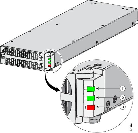
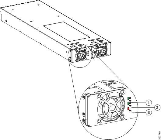
AC Power Modules |
Power status LEDs |
Input power indicator on (green): Input AC power OK. Output power indicator on (green): Output DC power OK. Fault LED off (red): No fault is present. The correct power module voltages are present and no faults have been detected. |
|
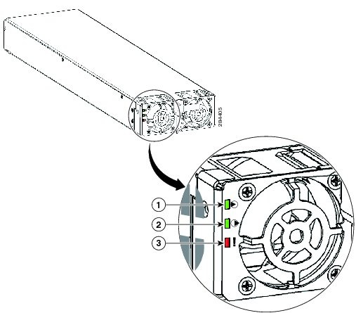
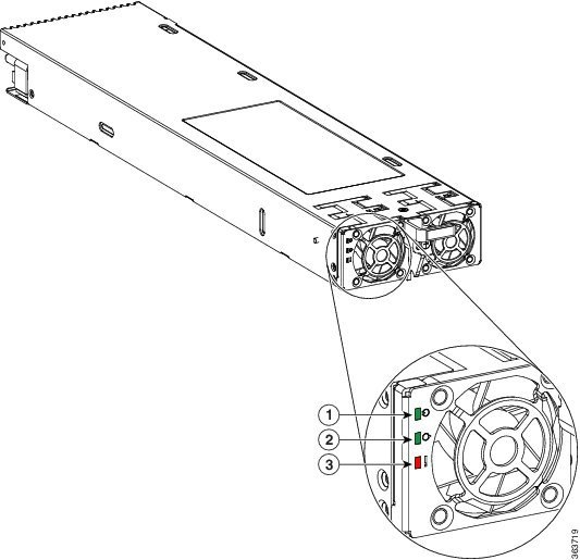
DC Power Modules |
Power status LEDs |
Input power indicator on (green): Input DC power OK. On the DC power tray, the Power Input LED is lit solid green if both DC feeds are valid and blinks green if only a single DC feed is valid. Output power indicator on (green): Output DC power OK. Fault LED off (red): No fault is present. The correct power module voltages are present and no faults have been detected. |
|
Fan Trays |
Fan tray status LED |
Green LED on: Fan Tray OK. The fan tray fans are operating correctly. |

 Feedback