Cisco Service Independent Intercept Architecture
Available Languages
Table Of Contents
Cisco Service Independent Intercept Architecture Version 1.0
Business Objectives of the Cisco SII LI Architecture
Key Requirements of LI Architecture
Cisco Service Independent Intercept Architecture
Mediation Device/Delivery Function
Intercept-Related Information Intercept Access Point
Communication Content Intercept Access Point
How Cisco SII LI Architecture Works
Cisco SII Voice Intercept Process Flows
Implementation of Cisco SII Lawful Intercept
Prerequisites and Design Considerations
Bandwidth and Processing Power Considerations
IP Address Provisioning Considerations
Aggregation Router Configurations
Cisco BTS 10200 Softswitch Call Agent Configuration
Cisco PGW 2200 Softswitch Call Agent Configuration
SS8 Networks Xcipio Mediation Device Configuration
Collection Function Configuration
Collection Function TCP Interface Configuration
IP Delivery Unit Configuration
Surveillance Record Configuration
IP Call Content Channel Configuration
Access Function SNMPv3 Configuration
Access Function Trunking Gateway Interface Configuration
Access Function BTS Provisioning Interface Configuration
Access Function PGW Provisioning Interface Configuration
Access Function RADIUS Interface Configuration
SNMP Alarms and Traps Configuration
Verifying the Cisco SII LI Network
Verifying the Cisco BTS 10200 Softswitch Call Agent Configuration
Verifying the Cisco PGW 2200 Softswitch Call Agent Configuration
Verifying the SS8 Mediation Device Configuration
Verifying the DNS Configuration From the Mediation Device
Verifying an Aggregation Router Configuration
Troubleshooting a Cisco SII LI Network
Troubleshooting the Mediation Device
Troubleshooting the BTS Call Agent
Troubleshooting the Call Agent Profile
Cisco Products That Support Lawful Intercept
Cisco Service Independent Intercept Architecture Version 1.0
Version History
Abstract
Cisco Service Independent Intercept (SII) architecture version 1.0 was developed in response to the needs of Cisco's service provider (SP) and Internet service provider (ISP) customers for compliance with Lawful Intercept (LI) legislation and regulations. It provides a common approach for intercepting IP communications using existing network elements.
LI is the process (not a specific regulatory requirement) by which law enforcement agencies (LEAs) conduct electronic surveillance as authorized by judicial or administrative order. Legislation and regulations are increasingly being adopted that requireSPs and ISPs to design and implement their networks to explicitly support authorized electronic surveillance. Types of SPs and ISPs that are subject to LI mandates vary greatly from country to country. The Cisco Service Independent Intercept Architecture Version 1.0 document describes the implementation of an LI architecture on a Cisco IP network that uses version 1.0 of Cisco LI Management Information Base (MIB) for Voice over IP (VoIP) and IP data intercepts.
This architecture is designed to support "plug-and-play" capability, which means that any architecture component can be replaced by any other Cisco SII-compliant component. Because of this flexibility in component choices, it is impractical for this document to completely describe all aspects of LI implementation for all of the possible components. Therefore, this document is intended as a high-level description of the end-to-end Cisco SII LI version 1.0 architecture including how LI works, the roles of the various components, and the available component options. The document also provides some information on design, implementation, operation, and troubleshooting of LI on a Cisco SII network. For detailed specifics on the various devices (such as image and memory requirements, configurations, and so on), this document references the product documentation of the devices.
Contents
This document contains the following sections:
•
Business Objectives of the Cisco SII LI Architecture
•
•
•
•
Business Objectives of the Cisco SII LI Architecture
The following sections describe the business objectives of implementing the Cisco SII LI architecture:
•
Key Requirements of LI Architecture
The following are the key requirements any LI architecture must meet:
•
•
•
•
•
Business Drivers
SPs and ISPs are required to meet LI requirements for voice and data in a variety of countries worldwide. Communications Assistance for Law Enforcement Act (CALEA) is a public law that describes how telephony service providers in the United States must support LI. In Europe there are a number of similar laws, including the Regulation of Investigatory Powers Act (RIPA) in the United Kingdom, the Telecom Act/Telekommunications Uberwachungsverordnung (TKUV) in Germany, the Telecom Act in France, the Criminal Code in Italy, and the Telecom Act in the Netherlands. However, in Europe, legal requirements and specific interfaces vary from country to country.
Two specifications define the interface to the LEAs for the purposes of meeting the CALEA requirements:
•
•
Cisco Service Independent Intercept Architecture
The following sections describe the Cisco SII version 1.0 of Cisco LI MIB architecture:
•
Overview
The SII architecture was developed in response to the needs of Cisco's SP and ISP customers for compliance with LI legislation and regulations. It provides a common approach for intercepting IP communications using existing network elements. The architecture addresses the key LI requirements mentioned earlier and does so in a cost-effective manner. Key features of the architecture include the following:
•
•
•

Note
•
•
•
•
Note
Network Topology
Figure 1 shows a functional depiction of a generic IP network that supports LI of voice or data traffic.
Figure 1 Functional Depiction of a Generic LI Network
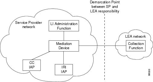
Note
The following sections describe the components that are integral to the Cisco SII network:
•
•
•
LI Administration Function
The SP and ISP uses the LI administration function to provision intercepts by interfacing with the other components in the network. It is responsible for provisioning components in the network, administering intercept orders, and tracking and maintaining intercept information. It also supervises the security and integrity of the LI process by continuously auditing activity logs to ensure that only authorized intercepts are provisioned and that authorized intercepts are not disrupted.
Note
Mediation Device/Delivery Function
The mediation device (MD) is maintained by the SP and ISP and is the center of the LI process. It sends configuration commands to the various IAPs to enable intercepts, receives intercept information (both IRI and CC), and delivers this information to the LEA. If more than one LEA is monitoring an intercept target, the mediation device duplicates the intercept information for each LEA. The mediation device is sometimes called the delivery function.
In some cases, the mediation device performs additional filtering of the information. It is also responsible for formatting the information to be compliant with the country or technology-specific requirements for delivery to law enforcement.
Mediation devices are third-party equipment. Cisco has performed end-to-end testing with a number of mediation device vendors. A list of these vendors can be found at the following URL: http://www.cisco.com/wwl/regaffairs/lawful_intercept/index.html
Intercept-Related Information Intercept Access Point
The Intercept-Related Information intercept access point (IRI IAP) is the device that provides identification information to the mediation device. IRI for voice includes the source and destination phone numbers and IP addresses and the time of the call. It also includes any post call-establishment messaging such as call forwarding or three-way calling. IRI for data includes login and logout times and source and destination IP addresses. For voice intercepts, the IRI IAP is the call control entity. The call control entity can be a call agent, Session Initiation Protocol (SIP) proxy, or H.323 gateway. For data intercepts, the IRI IAP is the authentication, authorization, and accounting (AAA) server.
Communication Content Intercept Access Point
The Communication Content IAP (CC IAP) is the device that intercepts communication content information, replicates it, and forwards the replicated information to the mediation device. The CC IAP should be located as close to the source of the call as possible to minimize the number of simultaneous calls the device will have to monitor and to ensure that CC can be reliably intercepted. The edge device is the only device that can guarantee CC intercept. The CC IAP can be an edge router, a trunking gateway, or an access server.
Collection Function
The collection function is a third-party device maintained by the LEA that receives, sorts, and stores intercept information from the mediation device. The collection function may also include case management capabilities.
Interfaces Between Devices
Figure 2 shows a functional depiction of the device interfaces in a Cisco SII network.
Figure 2 Functional Depiction of a Cisco SII LI Network
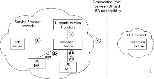
Figure 3 shows the device interfaces in the context of the specific devices that are used in a Cisco SII network.
Figure 3 Cisco SII Voice Intercept Device Interfaces
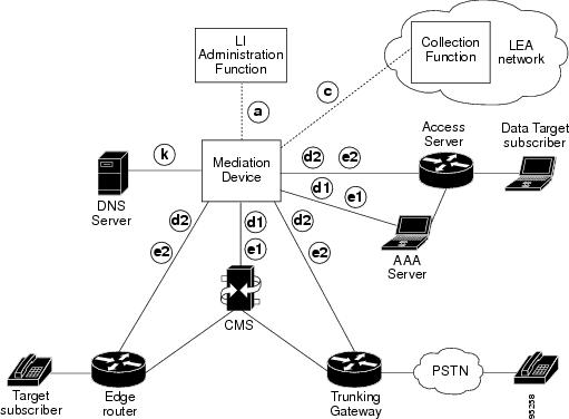
Note
Table 1 describes the interfaces between devices shown in Figure 2 and Figure 3.
Table 1 Cisco SII LI Network Device Interfaces
a
Authorization: administration function and mediation device
The LI administration function sends intercept provisioning information (target identifier, duration of intercept, and so on) to the mediation device.
c
Content: mediation device and collection function
The mediation device delivers intercept information to the collection function. If more than one LEA is intercepting the same target, the mediation device must duplicate the intercept information to send to the collection function of each LEA. This interface meets the specifications found in the PacketCable Electronic Surveillance Specification document in the "Related Documents" section.
d1
IRI Delivery: IRI IAP and mediation device
This is the delivery interface. The IRI IAP uses this interface to deliver IRI to the mediation device. For voice, this is according to the PacketCable Event Messages Specification document in the "Related Documents" section. For data, this is Remote Authentication Dial-In User Service (RADIUS) accounting messages.
For voice intercepts, the IRI IAP is the call control entity (call agent, SIP proxy, or H.323 gateway). For data intercepts, the IRI IAP is the AAA server (or a sniffer monitoring RADIUS traffic).
d2
CC delivery: CC IAP and mediation device
The call content (CC) IAP replicates CC and sends it to the mediation device. The CC IAP encapsulates the packets with additional UDP and IP headers and a 32-bit call content connection identifier (CCCID) header. (See the PacketCable Electronic Surveillance Specification document in the "Related Documents" section.) The CCCID is used to associate the CC with the target.
The CCCID is included so that the mediation device can map intercepts to the appropriate warrants. Usually, the mediation device will rewrite the CCCID before forwarding intercept information to collection functions.
The CC IAP is an edge router, trunking gateway, or access server.
e1
Provisioning: mediation device and IRI IAP
The mediation device uses Secure Shell (SSH) to provision an intercept on the IRI IAP.
e2
Provisioning: mediation device and CC IAP
The mediation device uses Simple Network Management Protocol version 3 (SNMPv3) to instruct the CC IAP to replicate CC and send it to the mediation device. The CC IAP can be either an edge router or a trunking gateway for voice. It is an edge router or access server for data.
k
DNS Lookup: mediation device and DNS server
The mediation device queries the Domain Name Service (DNS) server to determine the fully qualified domain name (FQDN) of the CC IAP.
How Cisco SII LI Architecture Works
The following sections describe how the Cisco SII LI architecture works:
•
Types of Intercepts
There are two types of intercepts:
•
•
Initiating an Intercept
When a warrant is issued, the LEA physically delivers the warrant to the SP or ISP. When the SP or ISP receives the warrant, it uses the LI administration function to enable LI on the target specified in the warrant. If the warrant is delivered prior to the authorized start date and time, the mediation device waits until the authorized start date and time to configure the tap. Once the intercept is provisioned on the mediation device, the process of initiating individual intercepts is completely automated.
Terminating an Intercept
When a warrant is issued, it includes an expiration date that is typically 30 days. This expiration date is configured on the mediation device. When the warrant expires, the mediation device automatically removes the configuration for the warrant. The mediation device provisioning interface can be used to remove a warrant before the expiration date.
Cisco SII Voice Intercept Process Flows
The following sections describe the various Cisco SII voice intercept process flows:
•
•
•
•
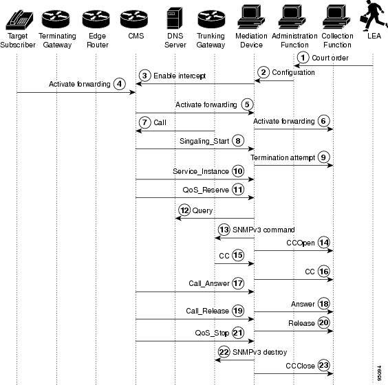
Standard Cisco SII Voice Intercept
Figure 4 shows the topology for a standard Cisco SII voice intercept.
Note
Figure 4 Standard Cisco SII Voice Intercept at Trunking Gateway or Aggregation Router
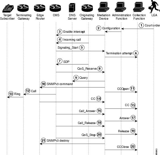
The following steps describe the sequence of events shown in Figure 4.
Step 1
Step 2
Step 3
Step 4
Step 5
Step 6
Step 7
Step 8
Step 9
Step 10
Step 11
Step 12
Step 13
Step 14
Step 15
Step 16
Step 17
Step 18
Step 19
Step 20
Step 21
Step 22
Hairpin Cisco SII Voice Intercept
Figure 5 shows the topology for a Cisco SII voice intercept in a hairpin scenario (when a call coming in from the PSTN to the intercept target is forwarded off the network and back to the PSTN).
Figure 5 Hairpin Cisco SII Voice Intercept at Trunking Gateway
The following steps describe the sequence of events shown in Figure 5.
Step 1
Step 2
Step 3
Step 4
Step 5
Step 6
Step 7
Step 8
Step 9
Step 10
Step 11
Step 12
Step 13
Note
Step 14
Step 15
Step 16
Step 17
Step 18
Step 19
Step 20
Step 21
Step 22
Note
Step 23
Cisco SII Three-Way Voice Intercept
Figure 6 shows the topology for a Cisco SII of a three-way voice conference call.
Figure 6 Cisco SII Three-Way Voice Intercept
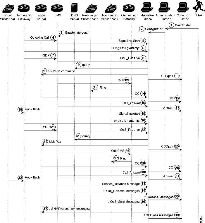
The following steps describe the sequence of events shown in Figure 6.
Step 1
Step 2
Step 3
Step 4
Step 5
Step 6
Step 7
Step 8
Step 9
Step 10
Step 11
Step 12
Step 13
Step 14
Step 15
Step 16
Step 17
Step 18
Step 19
Step 20
Step 21
Step 22
Step 23
Step 24
Step 25
Step 26
Step 27
Step 28
Step 29
Step 30
Step 31
Step 32
Step 33
Step 34
Step 35
Step 36
Step 37
Step 38
Cisco SII Call Forward to Voice Mail Intercept
Figure 7 shows the topology for a Cisco SII of a voice call that is forwarded to voice mail.
Figure 7 Cisco SII Call Forward to Voice Mail Intercept
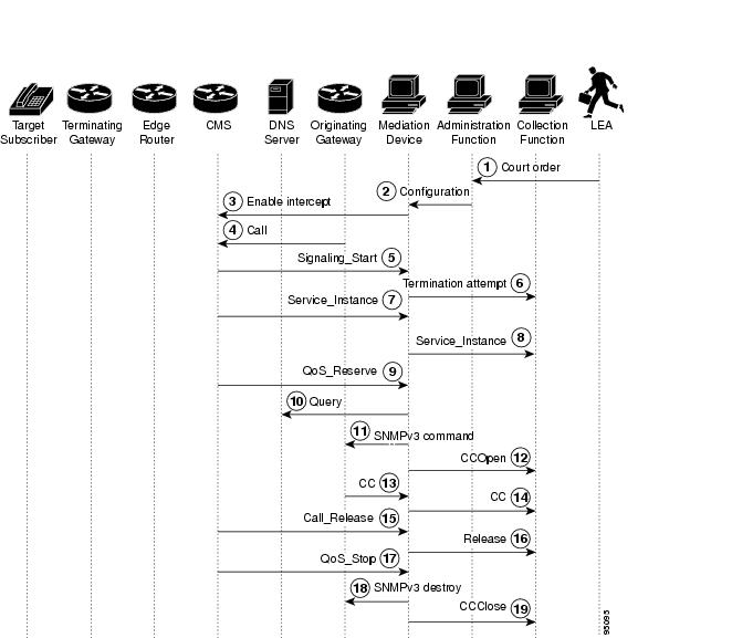
The following steps describe the sequence of events shown in Figure 7.
Step 1
Step 2
Step 3
Step 4
Step 5
Step 6
Step 7
Step 8
Step 9
Step 10
Step 11
Step 12
Step 13
Step 14
Step 15
Step 16
Step 17
Step 18
Step 19
Cisco SII Data Intercept
Figure 8 shows the topology for a Cisco SII data intercept.
Figure 8 Cisco SII Data Intercept
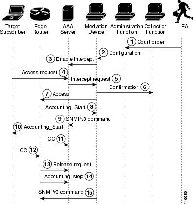
The following steps describe the sequence of events shown in Figure 8.
Step 1
Step 2
Step 3
Step 4
Step 5
Step 6
Step 7
Step 8
Step 9
Step 10
Step 11
Step 12
Step 13
Step 14
Step 15
Security Considerations
Given the sensitive nature of lawful intercept—both from the standpoint of the need to protect sensitive data, and to conceal the identities of law enforcement agencies and the intercept targets—the LI architecture must contain stringent security measures to combat the following types of threats:
•
•
•
•
Because LI is expected to run on the wide-open Internet, very few assumptions should be made about how well the networks of the LEA's, SP's, and ISP's can be secured. Although this document does not examine the issues of physical security, operating system, or application hardening within the principles of the LI architecture, they are clearly important considerations. In particular, both the MD and LEA servers must be considered prime targets for attacks by hackers. Hardening measures commensurate with other highly vulnerable servers, such as key distribution and AAA servers, must be considered in any design.
The following section describes security requirements:
•
Overall Security Requirements
All interfaces must be able to provide strong cryptographic authentication to establish the identity of the principles, and must correlate the identity of the principle with the action they are attempting to perform. That is, it is not sufficient to expect that authentication alone implies any specific authorization. Providing the ability to use strong crypto is not identical to requiring its use. Since many Cisco devices do not have crypto accelerators, actual use of crypto accelerators is the choice of the SP and ISP, and is dependent on how the device is deployed and its relative exposure. For devices placed in open, hostile environments (such as access routers), SPs and ISPs must consider customer requirements for LI when making decisions about crypto acceleration hardware.
Because LI is an interesting target for attackers, all interfaces must perform some sort of cryptographic message integrity checking (such as Hash-based Message Authentication Code [HMAC]-Message Digest 5 [MD5]). Message integrity checking must also counter replay attacks. Because of privacy and confidentiality considerations, the architecture should allow for the use of encryption. Although encryption is not necessarily a requirement, it is highly recommended and may be a requirement in some LI deployments.
Interface Between MD and IRI IAP: Control
SSH is used for the control interface between the MD and the IRI IAP.
Interface Between MD and CC IAP: SNMPv3 Control
SNMPv3 View-based Access Control Model (VACM) and User-Based Security Model (USM) are used for the control interface between the MD and the CC IAP. The native SNMPv3 security module mechanism must be used, and the minimum requirement is that preshared keys must be supported. The additional requirement is that the IAP must support the ability to protect the LI MIBs from disclosure or control by unauthorized USM users. In general VACM should provide the necessary tools to limit the views to particular USM users, but there are also special considerations given that USM and VACM provide the ability to create arbitrary view/user mappings to authorized entities. The security requirements of the Cisco Lawful Intercept Control MIB (CISCO-TAP-MIB) with respect to SNMP require the following actions:
•
•
•
–
–
SNMPv3 must be configured correctly to maintain security. The MD acts as a network manager and the CC IAP acts as an agent.
Interface Between MD and IRI IAP: Data
The IRI is delivered from the IRI IAP to the MD. This information is delivered in RADIUS format. Currently, this information is not encrypted.
Interface Between MD and CC IAP: Data
The CC information is delivered from the CC IAP to the MD. IP security (IPsec) (via standard router cryptographic features) is used for this interface.
Failure Recovery
The mediation device monitors the network elements involved in LI. If any network element involved in LI fails or anything else happens to interrupt an intercept, the MD implements an audit to ensure that all network elements are configured properly. If any problems are detected, the MD attempts to correct them. The errors are also reported to the LI administration function.
Note
Implementation of Cisco SII Lawful Intercept
The following section describes the implementation of the Cisco SII LI architecture:
•
Prerequisites and Design Considerations
Before configuring your network for LI, you must establish or verify reliable end-to-end IP connectivity on your existing network. The main concern when designing an LI network is ensuring that the network has sufficient bandwidth and CPU capacity to handle the anticipated load of intercepts. The following sections describe design considerations for implementing LI:
•
•
Bandwidth and Processing Power Considerations
The CPUs of the following devices will be impacted by LI:
•
•
•
The following interfaces must be engineered with sufficient bandwidth to support LI traffic:
•
•
•
You should also take into consideration that three-way calls require twice the bandwidth of regular calls because they require two pairs of transmit and receive channels.
You must also provision a network management system to perform DNS and Dynamic Host Configuration Protocol (DHCP) such as Cisco Network Registrar.
The use of SNMPv3 in SII requires that Network Time Protocol (NTP) is enabled and that all network elements involved in LI are synchronized to a stable time source.
The various devices involved in LI have minimum software and memory requirements that must be met. However, because of the number of possible devices and the fact that these requirements are subject to change, see the various product documents listed in the "Related Documents" section for the specific requirements.
IP Address Provisioning Considerations
In general, Cisco recommends that service providers not use static IP addresses, particularly for CPEs. Static provisioning of IP addresses is time consuming, expensive, and error prone. On the IAPs, it can be helpful to use loopback interfaces for the interface with the mediation device because the loopback interface remains constant if physical interfaces go out of service or if the routing path changes.
Device Configuration Files
The following sections provide detailed configuration information on the devices involved in LI:
•
•
•
•
Note
Aggregation Router Configurations
The following aggregation router platforms support version 1.0 of Cisco LI MIB:
•
•
•
•
•
•
•
The following configuration enables Cisco SII on an aggregation router using version 1.0 of the Cisco LI MIB:
7200-egw(config)# snmp-server view tapView CTapMIB included7200-egw(config)# snmp-server group tapGroup v3 auth read tapView write tapView notify tapView7200-egw(config)# snmp-server user mduserid tapGroup v3 auth md5 mdpasswdThe following configuration synchronizes the router's clock with the mediation device and enables SNMP traps to be sent to the mediation device:
7200-egw(config)# snmp-server enable traps snmp authentication linkdown linkup coldstart
warmstart
7200-egw(config)# snmp-server host 10.15.113.9 version 3 auth mduserid7200-egw(config)# ntp server 10.15.113.9The username "mduserid" and password "mdpasswd" must match the username and password that is provisioned on the mediation device for this particular router. In this case, the router's clock is synchronized to the mediation device's clock. A better option is to synchronize all devices in the network to an NTP time server.
Note
Cisco BTS 10200 Softswitch Call Agent Configuration
The following call agent profile must be provisioned on the Cisco Broadband Telephony Softswitch (BTS) 10200 softswitch call agent:
ADD CALL-AGENT-PROFILEID=CA146CMS_SUPP=NMGC_SUPP=NDQOS_SUPP=NCDB_BILLING_SUPP=NEM_BILLING_SUPP=NGTD_SUPP=NES_INTERCEPT_TYPE=SERVICE_INDEPENDENT_INTERCEPTCMS_ID=12345MGC_ID=56789FEID=54321Because the BTS 10200 call agent has no information about network topology and is not aware of aggregation routers, no configuration is necessary for aggregation routers.
On the call agent's profile for trunking gateways, local hairpinning must be disabled. The following line in the trunking gateway profile disables local hairpinning:
MGCP_HAIRPIN_SUPP=NCisco PGW 2200 Softswitch Call Agent Configuration
The Cisco PSTN Gateway 2200 (PGW 2200) softswitch call agent only operates in SII mode using PacketCable Event Messages Specification version I03. Provisioning on the Cisco PGW 2200 requires enabling the LI feature and identifying the mediation devices.
Before adding an MD to the Cisco PGW 2200, you should verify that LI is enabled by verifying that the "SysConnectDataAccess=true" and "LISupport=enable" parameters are set as shown in the /opt/CiscoMGC/etc/XECfgParm.dat file.
Following is an example of provisioning a mediation device using default RADIUS timeouts and retries. The recommended RADIUS key of 16 zeros is automatically provisioned.
mml> prov-add:extnode:name="mdname",type="LIMD",desc="Mediation_Device"mml> prov-add:lipath:name="md-path",desc'"MD_Path",extnode="aqsacom"mml> prov-add:iplnk:name="md-link",desc="MD_link",svc="md-path",ipaddr="IP_Addr2",port=14146,peeraddr="192.168.9.2",peerport=1813,pri=1In the above example, the value of "ipaddr" is selected from the /opt/CiscoMGC/etc/XECfgParm.dat file and must match the physical interface that has connectivity to the mediation device.
SS8 Networks Xcipio Mediation Device Configuration
The SS8 Networks Xcipio version 3.6.x mediation device runs on a series of Sun Microsystems workstations. The first workstation can handle all call data intercepts and up to five simultaneous communication content intercepts. Each additional workstation can handle up to 20 simultaneous communication content intercepts.
Note
The SS8 Networks Xcipio mediation device includes audio and visual alarms, and it can support secure sockets and other UNIX security measures.
Most (if not all) of the initial configuration of SS8 Networks Xcipio mediation devices is performed by SS8 Networks as part of the commissioning process. The following section describes the basics of configuring the Xcipio mediation device and is not meant as an authoritative guide.
The three methods of accessing the SS8 Networks Xcipio mediation device are through a CLI, a direct GUI, and a JAVA web interface. Except for surveillance information, all configurations must be done using Man-Machine Language (MML) commands. Surveillance information can be configured using the GUI or by the user calea_gui. Some configuration information (such as call agents) can be viewed using the GUI or user calea_gui but cannot be modified through the GUI or user calea_gui.
Calea_gui is an X Window application that must be run on the SS8 mediation device and displayed either locally or by being sent to a remote X Window server. The SS8 mediation device also supports a web interface that can be used to provision targets through any web browser or UNIX or LINUX workstation.
The built-in help feature for MML commands can display all available commands. To access the help level, enter the following command:
MML_calea_opr> help:;For detailed information on a command, enter the command in help mode followed by :;. For example, to display help information for the add-cf command, enter:
HELP_MML_CMD> add-cf:;
Note
The general format for MML commands is:
operation - object-of-operationwhen typical operations are ADD, DISPLAY, MODIFY, or DELETE, and typical objects of operation are collection function (cf) and TCP/IP collection function interface (tcpipcfi).
Note
The following configurations must be performed on the SS8 Xcipio mediation device:
•
•
•
•
•
•
•
•
•
•
•
•
Collection Function Configuration
The add-cf command adds the collection function and must be executed by user calea_adm.
MML_calea_adm> add-cf:cfid=1,name=PenLink;Table 2 describes the strings in the add-cf command.
Table 2 add-cf Command Strings
cfid
Collection function ID. Any number that has not already been used.
name
Any meaningful string to make the entry easily identifiable.
Collection Function TCP Interface Configuration
The add-tcpipcfi command adds the collection function to a TCP/IP interface. The command must be executed by user calea_adm.
MML_calea_adm> add-tcpipcfi:cfid=1,ipaddr=172.18.137.94,port=43000,reqstate=ACTIVE;Table 3 describes the strings in the add-tcpipcfi command.
IP Delivery Unit Configuration
The add-ipdu command adds the IP delivery unit (IPDU). The command must be executed by user calea_adm. The IPDU is used for the call content portion of intercepts, and up to 16 can be configured on the mediation device. The first IPDU is typically on the same Sun device as the Softswitch Delivery Function (SSDF), while additional IPDUs are located on separate Sun workstations.
MML_calea_adm> add-ipdu:ipduid=1,ipaddr=10.15.113.9,port=15001,hostname=brie;Table 4 describes the strings in the add-ipdu command.
IP Port Pools Configuration
The add-ipport command creates pools of ports for call content delivery. The command must be executed by user calea_adm. Both incoming and outgoing ports must be created.
MML_calea_adm> add-ipport:ipduid=1,portid=1,end_portid=10,direction=IN;MML_calea_adm> add-ipport:ipduid=1,portid=11,end_portid=20,direction=OUT;Table 5 describes the strings in the add-ipport command.
Surveillance Record Configuration
The add-surveillance command is used to add a record for each subject that is to be monitored for call data or call data and call content. It must be executed by user calea_opr. Most of the strings in this command must match corresponding strings provisioned on the LEA collection function. In particular, the caseid string is used as a key to uniquely identify surveillance data. For ease of reading, the command is divided into three lines. The command must be configured as one string with no spaces.
MML_calea_opr> add-surveillance:state=AA,county=main-county,city=Home-Town,warrantid=6789,caseid=1234,subsid=1111000001,startdate=05/01/2002,expdate=06/01/2002,cfid=1,survtype=CONTENT,content=COMBINED,user=calea_opr,access=PUBLIC;Table 6 describes the strings in the add-surveillance command.
AFTDN Configuration
The add-aftdn command adds the access function target directory number (AFTDN). It must be executed by user calea_opr. The AFTDN associates a subject with the call agent serving that subject. The AFTDN must be added after the surveillance record is configured (using the add-surveillance command).
MML_calea_opr> add-aftdn:subsid=2222111112,afid=Cable;Table 7 describes the strings in the add-aftdn command.
IP Call Content Channel Configuration
The add-ipccc command adds the IP call content channel (IPCCC) and must be executed by user calea_opr. The IPCCC associates a target subscriber with a particular collection function. The IPCCC must be added after the surveillance record and AFTDN have been configured.
MML_calea_opr> add-ipccc:ipcccid=1,cccid=0001,state=AA,county=main-county,city=Home-Town,
warantid=6789,subsid=3333000111,cfipaddr=172.18.137.56,cfport=9000;
Table 8 describes the strings in the add-ipccc command.
Access Function Configuration
The add-af command adds access functions (AF), which are devices that intercept call data or call content, including call agents, gateways, and aggregation routers. The command must be executed by user calea_adm.
If the network includes aggregation routers supporting SNMPv3 interfaces, they must also be added with the type of SNMPER. (SNMPER identifies devices that support an SII interface). Trunking gateways that support only MGCP LI options must be provisioned using type TGW. Trunking gateways that support SNMPv3 should be provisioned as such.
MML_calea_adm> add-af:afid=Cable,name=Cable,type=BTS10200,version=3.2,preprov=000:00;MML_calea_adm> add-af:afid=7246-1705,name=7246-1705,type=CMTS,version=12.2,preprov=000:00;MML_calea_adm> add-af:afid=AS5850-2,name=AS5850-2,type=TGW,version=12.1,preprov=000:00;MML_calea_adm> add-af:afid=ESR-egw,name=ESR-egw,type=SNMPER,version=12.2,preprov=000:00;Table 9 describes the strings in the add-af command.
Access Function SNMPv3 Configuration
The add-afsi command adds the access function SNMPv3 interface (AFSI), which contains information needed to interface with the provisioning interface for Cisco SNMPv3 interfaces. It must be executed by user calea_adm. The AFSI must be added after the corresponding access function has been added with the add-af command.
MML_calea_adm> add-afsi:afid=ESR-egw,ifid=1,domainname=ESR-egw.sm02.cisco.com,
ipaddr=10.15.115.3,port=161,reqstate=ACTIVE,username=ss8user,authpasswd=ss8passwd,
privpasswd=ss8passwd,securitylvl=AUTHNOPRIV;
Table 10 describes the strings in the add-afsi command.
Access Function Trunking Gateway Interface Configuration
The add-afti command adds the access function trunking gateway interface (AFTI). The command must be executed by user calea_adm. The AFTI contains information required to allow access to call content for calls passing through trunking gateways that support only the MGCP LI method. Gateways that support SNMPv3 interfaces are provisioned in the AFSI table. All gateways must also be provisioned in DNS in the same way as aggregation routers so that the mediation device can map an IP address to serving gateways with the pointer record (PTR) returned.
MML_calea_adm> add-afti;afid=AS5850-2,ifid=1,domainname=AS5850-2.sm02.cisco.com
ipaddr=10.15.111.6,protocol=MGCP,version=1.0;
Table 11 describes the strings in the add-afti command.
Note
Access Function BTS Provisioning Interface Configuration
The add-afbi command adds the access function BTS interface (AFBI), which provisions the interface that the SS8 SSDF uses to provision wiretaps on the BTS Element Management System (EMS). The command must be executed by user calea_adm. Because the EMS typically consists of active and standby units that each have different IP addresses, the add-afbi command must be configured for both units.
MML_calea_adm> add-afbi:afid=Cable,ifid=1,ipaddr=10.8.100.100,username=caleapasswd=test123,reqstate=ACTIVE;MML_calea_adm> add-afbi:afid=Cable,ifid=2,ipaddr=10.8.100.101,username=caleapasswd=test123,reqstate=ACTIVE;Table 12 describes the strings in the add-afbi command.
Note
Access Function PGW Provisioning Interface Configuration
The add-afgi command adds the access function PGW interface (AFGI), which provisions the interface that the SS8 SSDF uses to provision wiretaps on the PGW. The command must be executed by user calea_adm. Because the PGW typically consists of an active and standby unit that each have different IP addresses, the add-afgi command must be configured for both units.
MML_calea_adm> add-afgi:afid=PGW,ifid=1,ipaddr=10.15.113.80,username=liusr,passwd=test123,reqstate=ACTIVETable 13 describes the strings in the add-afgi command.
Access Function RADIUS Interface Configuration
The add-afri command adds the access function RADIUS interface (AFRI), which provisions the PacketCable Event Message interface between the call agent and the SS8 mediation device. The command must be executed by user calea_adm. As with the add-afbi command, the add-afri command must be performed for both active and standby call agent units. The AFID is the same for both, and the IFID is unique for each.
MML_calea_adm> add-afri:afid=Cable,ifid=1,ipaddr=10.8.100.102,port=14146,reqstate=ACTIVE,version=I03,sharedsecret=0000000000000000;MML_calea_adm> add-afri:afid=Cable,ifid=2,ipaddr=10.8.100.103,port=14146,reqstate=ACTIVE,version=I03,sharedsecret=0000000000000000;MML_calea_adm> add-afri:afid=7246-I1705,ifid=1,ipaddr=10.8.104.5,port=1646,reqstate=ACTIVE,version=I03,sharedsecret=0000000000000000;Table 14 describes the strings in the add-afri command.
In this example, port 14146 is the default source port used by the BTS. If port validation for security is not desired, then the port number in AFRI can be set to 0 (zero).
SNMP Alarms and Traps Configuration
The add-almdest command configures SNMP alarms. It must be executed by user calea_adm.
MML_calea_adm> add-almdest:name=SNMP,type=SNMP;MML_calea_adm> add-almstream:name=SNMP,group=ALL,module=ALL,number=ALL,severity=ALL, type=ALL;The add-almstream command configures SS8 to send SNMP traps to the network management system. It must be executed by user calea_adm.
MML_calea-adm> add-almstream:name=SNMP,group=ALL,module=ALL,number=ALL,severity=ALL,
type=PASS;
For information on editing files to set up the addresses and ports of the SNMP network management server, see the SS8 Xcipio SSDF User Manual in the "Related Documents" section. The files that need to be edited will depend upon whether the network management server supports SNMPv1 or SNMPv2. The SS8 MIB definition files will also need to be installed into the network management software.
DNS Server Configuration
The DNS server must be provisioned to allow the mediation device to map the gateway to the aggregation router. Table 15 shows a DNS resource record entry that maps a range (an entire C class) of Integrated Access Device (IAD) endpoint IP addresses to the serving aggregation router, ESR-eg2.sm02.cisco.com.
Table 15 DNS Server Configuration
0
—
PTR
ESR-egw.sm02.cisco.com
0
—
A
255.255.255.0
For SSDF to map an analog access device IP to the serving aggregation router, DNS must be configured according to RFC 1101, DNS Encoding of Network Names and Other Types.
Note
Verifying the Cisco SII LI Network
The following sections describe how to verify that the Cisco SII LI network has been configured correctly:
•
•
•
•
•
Verifying the Cisco BTS 10200 Softswitch Call Agent Configuration
The following commands can be used to verify the LI configuration on the Cisco BTS 10200 softswitch call agent. Each of these EXEC commands can be issued only by the user calea.
CLI> show essReply: Success: Entry 1 of 1 returned.CDC_DF_PORT=1813CDC_DF_ADDRESS=10.8.100.17ENCRYPTION_KEY=0000000000000000ACC_REQ_RETRANSMIT=3ACC_RSP_TIMER=2CLI>BTS> show wiretapReply: Success: Entry 1 of 1 returned.SUBSCRIBER_DN=3065050208SUB_ID=arr050208/1TAPTYPE=INTERCEPTCDC_DF_ADDRESS=10.8.100.17CDC_DF_PORT=1813CCC_DF_ADDRESS=10.8.100.17CCC_DF_PORT=45007CLI>CLI> show wiretap subscriber_dn=6213000001SUBSCRIBER_DN=6213000001TAPTYPE=INTERCEPTCDC_DF_ADDRESS=10.15.113.9CDC_DF_PORT=1813CCC_DF_ADDRESS=10.15.113.9CCC_DF_PORT=45010Reply: Success: Entry 1 of 1 returnedCLI>Use the show call-agent-profile EXEC command to verify the call agent profile. This command must be issued by a user with generic provisioning access and not by user "calea."
BTS>show call-agent-profileReply : Success: Entry 1 of 1 returned.ID=CA146CMS_ID=12345MGC_ID=56789FEID=54321CMS_SUPP=YMGC_SUPP=YDQOS_SUPP=YCDB_BILLING_SUPP=NEM_BILLING_SUPP=YGTD_SUPP=NES_INTERCEPT_TYPE=SERVICE_INDEPENDENT_INTERCEPTVerifying the Cisco PGW 2200 Softswitch Call Agent Configuration
Use the following commands to verify the configuration on the Cisco PGW 2200 softswitch call agent configuration.
To verify the mediation device configuration, enter the following commands from a PGW user that is authorized to access MML:
mml> prov-rtrv:extnode:name="name of mediation device"mml> prov-rtrv:lipath:name="name of path to MD"mml> prov-rtrv:iplnk:name="name of link to MD"mml> prov-rtrv:sigsvcprop:name="name of path to MD"
Note
To verify the wiretap configuration, enter the following commands from a PGW user that is authorized to access the wiretap command set:
mml> wiretap-rtrv:subscriber:number="target's phone number"mml> wiretap-rtrv:subscriber:"all"Verifying the SS8 Mediation Device Configuration
The following commands can be used to verify the SS8 mediation device configuration. For more information on verifying the SS8 mediation device, see the SS8 Xcipio SSDF User Manual in the "Related Documents" section.
MML_TH> display-almdest:;-----------------------------------------------------------------NAME TYPE DEST ARG STATUS-----------------------------------------------------------------CONSOLE CONSOLE stdout OKLOG LOGFILE /opt/SS8/access/AlarmLogs AccessAlarms.0 OKPANEL PANEL 0x16000001 819296 OKSNMP SNMP OK<SUCCESS>:: 4 records found.MML_TH> display-almstream:;-----------------------------------------------NAME GROUP MODULE NUMBER SEVERITY TYPE-----------------------------------------------CONSOLE ALL ALL ALL ALL PASSLOG ALL ALL ALL ALL PASSPANEL ALL ALL ALL ALL PASSSNMP ALL ALL ALL ALL PASS<SUCCESS>:: 4 records found.MML_TH> display-ipdu:;-----------------------------------------------------------------------------------IPDUID HOSTNAME IPADDR PORT STATE INSTR INEND OUTSTR OUTEND-----------------------------------------------------------------------------------1 swiss 10.15.93.29 15001 ACTIVE 45001 45128 45129 45512<SUCCESS>:: 1 records found.MML_TH> display-ipport:;---------------------------------------------IPDUID PORTID PORT DIRECTION PROTOCOL STATE---------------------------------------------1 1 45010 IN UDP BUSY1 2 45009 IN UDP BUSY1 3 45008 IN UDP IDLE1 4 45007 IN UDP IDLE1 5 45006 IN UDP IDLE1 6 45005 IN UDP IDLE1 7 45004 IN UDP IDLE1 8 45003 IN UDP IDLE1 9 45002 IN UDP IDLE1 10 45001 IN UDP IDLE1 11 45138 OUT UDP BUSY1 12 45137 OUT UDP BUSY1 13 45136 OUT UDP IDLE1 14 45135 OUT UDP IDLE1 15 45134 OUT UDP IDLE1 16 45133 OUT UDP IDLE1 17 45132 OUT UDP IDLE1 18 45131 OUT UDP IDLE1 19 45130 OUT UDP IDLE1 20 45129 OUT UDP IDLE<SUCCESS>:: 20 records found.MML_TH> display-cf:;--------------------------------------------------------CFID NAME TYPE GRP1 GRP2 GRP3 GRP4 CARRIER--------------------------------------------------------1 CF-1 TCPIP N/A N/A N/A N/A 0002 CF-2 TCPIP N/A N/A N/A N/A 000<SUCCESS>:: 2 records found.MML_TH> display-tcpipcfi:;-------------------------------------------------------------CFID OWNIP IPADDR PORT REQSTATE STATE-------------------------------------------------------------1 172.18.137.105 172.18.137.94 43001 ACTIVE ACTIVE2 172.18.137.105 172.18.137.56 43001 ACTIVE ACTIVE<SUCCESS>:: 2 records found.MML_TH> display-af:;------------------------------------------------------------------------------------------AFID NAME TYPE SERIAL VERSION PREPROV INDEX------------------------------------------------------------------------------------------7246-I1705 7246-I1705 SNMPER N/A 12.3 000:00 3Beyond Beyond BTS10200 N/A 4.4 000:00 1Cable Cable BTS10200 N/A 4.4 000:00 27200-egw 7200-egw SNMPER N/A 12.4 000:00 27500-egw 7500-egw SNMPER N/A 12.4 000:00 3ESR-egw ESR-egw SNMPER N/A 12.2 000:00 1<SUCCESS>:: 6 records found.MML_TH> display-afbi:;------------------------------------------------------------------------------------------AFID IFID IPADDR REQSTATE STATE USERNAME PASSWD------------------------------------------------------------------------------------------Beyond 1 10.15.69.7 INACTIVE INACTIVE calea test123Cable 1 10.8.100.100 ACTIVE ACTIVE calea test123Cable 2 10.8.100.101 ACTIVE INACTIVE calea test123<SUCCESS>:: 3 records found.MML_calea> display-afgi:;------------------------------------------------------------------------------------------AFID IFID IPADDR REQSTATE STATE USERNAME------------------------------------------------------------------------------------------PGW 1 10.15.113.80 ACTIVE ACTIVE liusr<SUCCESS>:: 1 record found.MML_TH> display-afsi:;------------------------------------------------------------------------------------------------------------------------------------------------------AFID IFID DOMAINNAME IPADDR PORT REQSTATE STATE USERNAMEAUTHPASSWD PRIVPASSWD SECURITYLVL------------------------------------------------------------------------------------------------------------------------------------------------------7200-egw 1 7200-egw.sm02.cisco.com 10.15.115.1 161 ACTIVE ACTIVE ss8userss8passwd ss8passwd AUTHNOPRIV7500-egw 1 7500-egw.sm02.cisco.com 10.15.115.2 161 ACTIVE ACTIVE ss8userss8passwd ss8passwd AUTHNOPRIVESR-egw 1 ESR-egw.sm02.cisco.com 10.15.115.3 161 ACTIVE ACTIVE ss8userss8passwd ss8passwd AUTHNOPRIV<SUCCESS>:: 3 records found.MML_TH>MML_TH> display-afti:;------------------------------------------------------------------------------------------AFID IFID DOMAINNAME IPADDR PORT REQSTATE STATE PROTOCOL VERSION------------------------------------------------------------------------------------------AS5850-2 1 AS5850-2.sm02.cisco.com 10.15.111.6 2427 ACTIVE ACTIVE MGCP 1.0mgxc701-11 1 mgxc701-11.sm02.cisco.com 10.15.112.193 2427 ACTIVE ACTIVE MGCP 1.0<SUCCESS>:: 2 records found.MML_TH>MML_TH> display-afri:;---------------------------------------------------------------------------------AFID IFID IPADDR PORT REQSTATE VERSION SHAREDSECRET---------------------------------------------------------------------------------PGW 1 10.15.113.80 14146 ACTIVE I03 0000000000000000PGW 2 10.15.113.81 14146 ACTIVE I03 00000000000000007246-I1705 1 10.8.104.5 1646 ACTIVE I03 0000000000000000Beyond 1 10.15.69.35 1813 ACTIVE I03 0000000000000000Beyond 2 10.15.69.36 1813 ACTIVE I03 0000000000000000Beyond 3 10.15.69.67 1813 ACTIVE I03 0000000000000000Beyond 4 10.15.69.68 1813 ACTIVE I03 0000000000000000Cable 1 10.8.100.102 14146 ACTIVE I03 0000000000000000Cable 2 10.8.100.103 14146 ACTIVE I03 0000000000000000<SUCCESS>:: 7 records found.MML_TH>MML_TH> display-surveillance:;------------------------------------------------------------------------------------------------------------------------------------------------------------------------------------STATE COUNTY CITY WARRANTID JAREA CASEIDSUBSID ENTRYDATE STARTDATE EXPDATE STATUS CFID SURVTYPE CONTENT USERACCESS------------------------------------------------------------------------------------------------------------------------------------------------------------------------------------ AA Main-County Home-Town 0305 COUNTRY 03059844950305 08/30/2002 08/30/2002 12/31/2002 ACTIVE 1 DATA NONE calea_oprPUBLICAA Main-County Home-Town 0306 COUNTRY 03069844950306 08/22/2002 08/22/2002 12/30/2002 ACTIVE 2 DATA NONE calea_oprPUBLICAA Main-County Home-Town 0308 COUNTRY 03089844950308 08/22/2002 08/22/2002 12/31/2002 ACTIVE 2 CONTENT COMBINED calea_oprPUBLICAA Main-County Home-Town 9192621001 COUNTRY 10019192621001 09/30/2002 09/30/2002 12/31/2003 ACTIVE 2 CONTENT COMBINED calea_oprPUBLICAA Main-County Home-Town 9844950307 COUNTRY 03079844950307 10/01/2002 10/01/2002 11/01/2003 ACTIVE 2 CONTENT COMBINED calea_oprPUBLIC<SUCCESS>:: 5 records found.In the following output from the display-aftdn:; command, the first and last rows of output are for call data only. The three middle rows are for call data and call content. The SSDF software automatically selects the IP address and port number.
MML_TH> display-aftdn:;------------------------------------------------------------------------------SUBSID AFID IPADDR PORT REQSTATE STATE------------------------------------------------------------------------------9192621001 Cable 10.8.100.17 45009 ACTIVE PROVED9844950305 Cable N/A 0 ACTIVE PROVED9844950306 Cable N/A 0 ACTIVE PROVED9844950307 Cable N/A 0 ACTIVE TOBEPROV9844950308 Cable 10.8.100.17 45010 ACTIVE PROVED<SUCCESS>:: 5 records found.MML_TH>MML_TH> display-ipccc:;---------------------------------------------------------------------------------------------------------------------------------------IPCCCID STATE COUNTY CITY WARRANTID CCCIDSUBSID CFIPADDR CFPORT STATUS---------------------------------------------------------------------------------------------------------------------------------------1 AA Home-Town Home-Town 0308 03089844950308 172.18.137.56 9000 ACTIVE8 AA Home-Town Home-Town 9192621001 10019192621001 172.18.137.56 9000 ACTIVE<SUCCESS>:: 2 records found.Verifying the DNS Configuration From the Mediation Device
The following commands can be used to verify that DNS is properly configured from the SS8 mediation device. The first example of the nslookup command verifies that the PTR record is properly configured. The IP address of the target's IAD loopback interface is 10.142.133.2. Therefore, to mask the last octet of the IP address, the lookup is performed for 0.133.142.10.
brie% nslookup -type=PTR 0.133.142.10.in-addr.arpaServer: aulander.cisco.comAddress: 172.18.135.890.133.142.10.in-addr.arpa name = ESR-egw.sm02.cisco.com133.142.10.in-addr.arpa nameserver = sm02cnra.sm02.cisco.comThe second example of the nslookup command verifies that the A record is properly configured. The IAD address is used.
brie% nslookup -type=A 0.133.142.10.in-addr.arpaServer: aulander.cisco.comAddress: 172.18.135.89Name: 0.133.142.10.in-addr.arpaAddress: 255.255.255.0To subsequently determine the IP address of the edge router, the net mask is "AND"ed with the original target IP address, and another nslookup command is performed.
Verifying an Aggregation Router Configuration
The following commands can be used to verify the SNMPv3 configuration on an aggregation router. The show snmp view command displays SNMPv3 LI information, where the tapView line is the line of interest.
ESR-egw# show snmp view*ilmi system - included permanent active*ilmi atmForumUni - included permanent activetapView cTapMIB - included nonvolatile activev1default internet - included volatile activev1default internet.6.3.15 - excluded volatile activev1default internet.6.3.16 - excluded volatile activev1default internet.6.3.18 - excluded volatile activeThe show snmp group command displays information on SNMP groups, where the tapGroup line is the line of interest.
ESR-egw# show snmp groupgroupname: ILMI security model:v1readview :*ilmi writeview: *ilminotifyview: <no notifyview specified>row status: activegroupname: ILMI security model:v2creadview :*ilmi writeview: *ilminotifyview: <no notifyview specified>row status: activegroupname: tapGroup security model:v3 authreadview :tapView writeview: tapViewnotifyview: tapViewrow status: activeThe show snmp user command displays information about configured users of SNMP.
ESR-egw# show snmp userUser name: mediation-deviceEngine ID: 0000000902000200000000A0storage-type: nonvolatile activeUser name: md-adminEngine ID: 0000000902000200000000A0storage-type: nonvolatile activeTroubleshooting a Cisco SII LI Network
The following sections provide guidance in troubleshooting a Cisco SII LI network:
•
•
•
•
General Troubleshooting Notes
The most common problem encountered in configuring LI on a network is general networking problems. All of the involved devices must have static IP addresses, and most require the use of specific ports. All of the firewalls involved (end customer, SP, ISP, LEA, and so on) must allow the static IP addresses and port numbers to go through. When firewalls prohibit ping traffic, pings cannot be used for troubleshooting. Instead, you may have to use a sniffer to verify connectivity.
Another common problem is mismatched usernames and passwords. The following sections include details about the device interfaces that must have matching usernames and passwords.
Troubleshooting the Mediation Device
If you have trouble with a mediation device, first check the mediation device logs and alarms. In case of serious trouble, the mediation devices have various tracing mechanisms. On the SS8 Xcipio mediation device, if the file /etc/resolv.conf is edited to add or modify IP addresses of DNS servers while the CALEA application is running, CALEA must be stopped and restarted (using the calea_stop and calea_start commands) before the application will recognize the configuration changes. For more information on troubleshooting the SS8 Xcipio mediation device, see the SS8 Xcipio SSDF User Manual in the "Related Documents" section.
When SNMPv3 is used, the usernames, passwords, and security levels provisioned on the mediation device must match those provisioned on the aggregation devices.
If the IP address or port number provisioned on the mediation device for the collection function is incorrect, the collection function will appear in the "FAIL" state on the mediation device, and logs on the mediation device will detail connection attempt failures. On the SS8 mediation device, the logs are located at $ASVCRUN/mlog/Mlog[date]. If the port number for call content delivery to the collection function is incorrect, the collection function will never receive call content.
The mediation device log files will also contain error records if incorrect IP addresses or port numbers are provisioned for the call agent, aggregation routers, or edge routers.
Troubleshooting the BTS Call Agent
To perform Electronic Surveillance Subsystem (ESS) and wiretap commands on the BTS, you must log in as user calea. All other commands can be entered by any user with the proper permissions.
When accessing the BTS, you must log in as user calea. The username and password must match those provisioned on the mediation device.
The BTS will not function properly if the $ASVCRUN/config/MML/btsrhost.cnf file is not properly edited to change it from Telnet to SSH. Six lines in the file need to be edited, which are described in the software installation instructions.
The following section describes troubleshooting procedures on the BTS call agent.
For more information on debugging and tracing tools for the BTS, see the Cisco BTS 10200 Documentation Access Information document in the "Related Documents" section.
Troubleshooting the Call Agent Profile
Enter the show call-agent-profile EXEC command to verify the call agent profile:
BTS> show call-agent-profileReply : Success: Entry 1 of 1 returned.ID=CA146CMS_ID=12345MGC_ID=56789FEID=54321CMS_SUPP=YMGC_SUPP=YDQOS_SUPP=YCDB_BILLING_SUPP=NEM_BILLING_SUPP=YGTD_SUPP=NES_INTERCEPT_TYPE=SERVICE_INDEPENDENT_INTERCEPTThe EM_BILLING_SUPP, CMS_SUPP, and MGC_SUPP all must be set to Y. The CMS_ID, MGC_ID, and financial entity ID (FEID) all must be set to nonzero numbers.
CMS_SUPP controls the sending of event messages when an on-network (on-net) endpoint is involved in the call. If MGC_SUPP is set to Y, the BTS will send event messages; if it is set to N, the BTS will not send event messages.
CMS_ID, MGC_ID, and FEID are PacketCable network element identifiers. Unique values for these network elements must be agreed upon by all involved parties. For the purposes of settlements, PacketCable zones are divided into one or more logical financial entities. A single call agent is assigned at most one FEID. One or more call agents may be assigned the same FEID.
MGC_SUPP controls the sending of event messages when an off-net endpoint is involved in the call. If MGC_SUPP is set to Y, the BTS will send event messages; if it is set to N, the BTS will not send event messages.
Appendix
This section contains the following information:
•
•
Cisco Products That Support Lawful Intercept
Table 16 provides the following additional information on the Cisco products that support LI:
•
•
•
–
–
–
•
–
–
–
Related Documents
Table 17 lists related documents.
Standards
MIBs
•
To locate and download MIBs for selected platforms, Cisco IOS releases, and feature sets, use Cisco MIB Locator found at the following URL:
RFCs
RFC 1101
DNS Encoding of Network Names and Other Types
RFC 3924
Cisco Architecture for Lawful Intercept in IP Networks
Technical Assistance
Glossary
AAA—authentication, authorization, and accounting
AF—access function
AFBI—access function BTS interface
AFGI—access function PGW interface
AFID—access function ID
AFRI—access function Radius interface
AFSI—access function SNMPv3 interface
AFTDN—access function target directory number
AFTI—access function trunking gateway interface
BTS—Broadband Telephony Softswitch. A call agent.
CALEA—Communications Assistance for Law Enforcement Act
CC—call content
CCC—call content connection
CCCID—call content connection identifier
CC IAP—Communication Content intercept access point
CFID—collection function ID
CISCO-TAP-MIB—Cisco Lawful Intercept Control MIB
CLI—command-line interface
CMS—call management server
CMTS—cable modem termination system
CPE—customer premise equipment
CSG—Content Services Gateway
DCFD—Data Collection and Filtering Device. A sniffer that collects and analyzes RADIUS traffic.
DHCP—Dynamic Host Configuration Protocol
EMS—Element Management System
ESR—Edge Services Router
ESS—Electronic Surveillance Subsystem
FEID—financial entity ID
FQDN—fully qualified domain name
GSR—Gigabit Switch Router
HMAC—Hash-based Message Authentication Code
IAD—Integrated Access Device
IFID—Interface ID
IPCCC—IP call content channel
IPDU—IP delivery unit
IPDUID—IP delivery unit ID
IPsec—IP security
IRI IAP—Intercept-Related Information intercept access point
ISP—Internet service provider
L2TP—Layer 2 Tunneling Protocol
LEA—law enforcement agency
LI—lawful intercept
MD—mediation device. A hardware device that receives signal and voice information from an SP or ISP network and translate the information into the correct protocol.
MD5—Message Digest 5
MGC—Media Gateway Controller
MGCP—Media Gateway Control Protocol
MIB—Management Information Base
MML—Man Machine Language
NTP—Network Time Protocol
off-net—off-network
on-net—on-network
PGW—PSTN Gateway
PSTN—public switched telephone network
PTR—pointer record
RADIUS—Remote Authentication Dial-In User Services
reqstate—required state
RIPA—Regulation of Investigatory Powers Act
SDP—Session Definition Protocol
SII—Service Independent Intercept
SIP—Session Initiation Protocol
SM—Telecordia Service Manager. A call agent.
SMDS—Switched Multimegabit Data Service
sniffer—A network analyzer used to capture packets transmitted in a network for inspection and problem detection.
SNMPv3—Simple Network Management Protocol version 3
SP—service provider
SSDF—Softswitch Delivery Function. A software program provided by SS8 Networks called Xcipio SSDF.
SSH—Secure Shell
tcpipcfi—TCP/IP collection function interface
TGW—trunking gateway
TIA—Telephone Industry Association
TKUV—Telekommunications Uberwachungsverordnung
uBR—Universal Broadband Router
UDP—User Datagram Protocol
USM—User-based Security Model
VACM—View-based Access Control Model
VISM—Voice Interworking Service Module
VoIP—Voice over IP
VXSM—Voice Switch Service Module
Note
Any Internet Protocol (IP) addresses used in this document are not intended to be actual addresses. Any examples, command display output, and figures included in the document are shown for illustrative purposes only. Any use of actual IP addresses in illustrative content is unintentional and coincidental.
© 2006 Cisco Systems, Inc. All rights reserved.
 Feedback
Contact Cisco
- Open a Support Case

- (Requires a Cisco Service Contract)
This Document Applies to These Products
- Collaboration Endpoints - Retired Products
- Conferencing - Retired Products
- Contact Center - Retired Products
- Optical Networking - Retired Products
- Routers - Retired Products
- Security - Retired Products
- Servers - Unified Computing (UCS) Retired Products
- Storage Networking Retired Products
- Switches - Retired Products
- Video - Retired Products
- Wireless - Retired Products