Provision a LAN Underlay

LAN automation

Catalyst Center provides LAN automation as an alternative for manual deployment of new networks. This automation allows you to simplify network operations and create a standard error-free network. LAN automation uses the IS-IS routing protocol to deploy a Layer 3 routed access design.

LAN Automation provides these capabilities:

  • Provision your network through LAN automation

  • View the history of LAN automation sessions

  • View the summary of LAN automated devices

From the main menu, choose Provision > LAN Automation to view this window.

  • Start LAN Automation: Use this option to initiate LAN automation sessions on your network.

  • Overview: Expand this section to view the prerequisites and more information about provisioning your network through LAN automation.

  • Sessions: This section consists of the History of LAN automation sessions, and the list of LAN Automated Devices.

Day-Zero Operation

On day zero, click Start LAN Automation to start provisioning your network through LAN automation. For more information, see Provision a network through LAN automation.

For day zero, Catalyst Center doesn't display any data in the Sessions section.

Day-n Operation

On day n, you can click Start LAN Automation to initiate more LAN automation sessions. You can run up to five LAN automation sessions simultaneously across sites. For more information, see Provision a network through LAN automation.

When a LAN automation session is in progress, Catalyst Center displays a tile for the session on the LAN Automation window. To view the details of the session, click See Session Details in the tile. To stop LAN automation for the session, click Stop LAN Automation in the tile.

The History tab displays the history of LAN automation sessions in your network. You can use the Search field to search for specific text. To view the session details, click the hyperlinked date. To view the logs for a session, in the session details window, click View Session Logs.

The LAN Automated Devices tab displays the details of the LAN automated devices. You can use the search field to filter the data based on specific text. Click one of these toggle buttons to filter the data:

  • Seed Devices: Displays the data for seed devices

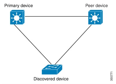
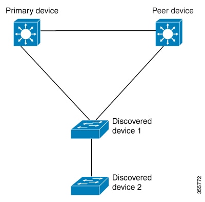
  • Discovered: Displays the data for discovered devices

  • Provisioned: Displays the data for provisioned devices

  • Error: Displays the data for devices with errors

In the LAN Automated Devices tab, you can also do these tasks:

  • Click the device name hyperlink to view the device details.

  • Provision interfaces between two devices by clicking Add Link. For more information, see Create a link between interfaces.

  • Delete the interface between two devices by clicking Delete Link. For more information, see Delete a link between interfaces.

  • Customize the hostname and loopback IP address of a device by clicking Edit Device.


    Note


    • To edit the hostname and loopback IP address of a device on Day-n, the device must be in the Managed state in the Inventory.

    • You can edit the loopback IP addresses of a maximum of 25 devices in a single Day-n workflow.


    For more information, see Edit Loopback IP Address of LAN Automated Devices.

Prerequisites for provisioning a network through LAN automation

Before provisioning a network through LAN automation, ensure these prerequisites are met:

  • Configure your network hierarchy. (See Assign an unprovisioned device to a site.)

  • Define these global network settings:

  • Ensure you have at least one device in your inventory. If not, discover devices using the Discovery feature.


    Note


    LAN automation is blocked if the discovered site is configured with "cisco" in the username of your CLI credentials.


  • If you have a Cisco Catalyst 9400 Switch configured in the network, these operations must be completed on the switch for LAN automation to automatically enable the 40G port:

    • The day-zero configuration is performed on the switch.

      For more information, see “Initial Configuration for the Switch” in the Cisco Catalyst 9400 Series Switches Hardware Installation Guide.

    • A 40G Quad Small Form-Factor Pluggable (QSFP) transceiver is inserted in either port 9 or port 10 of the Supervisor, and the ports numbered 1 to 8 on the Supervisor do not have a 10G or 1G Small Form-Factor Pluggable (SFP) transceiver that is inserted in them. If there are dual supervisor engines, ensure that the 40G QSFP is inserted in port 9.

      For more information on the Catalyst 9400 Series Supervisor, see the “Uplink Ports” topic in the Cisco Catalyst 9400 Series Supervisor Module Installation Note.

Provision a network through LAN automation

Before you begin

Make sure that the prerequisites have been met. For more information, see Prerequisites for provisioning a network through LAN automation.

Procedure


Step 1

Reserve an IP address pool for the site that you are provisioning.

Note


The size of the LAN automation IP address pool must be at least 25 bits of netmask or larger.

  1. From the main menu, choose Design > Network Settings > IP Address Pools.

  2. From the left hierarchy tree, select the required site.

  3. Click Reserve.

  4. In the Reserve IP Pool slide-in pane, complete these fields to reserve all or part of an available global IP address pool for the selected site:

    • IP Address Pool Name: Unique name for the reserved IP address pool.

    • Type—Type of IP address pool:

      • LAN: Assigns IP addresses to LAN interfaces for applicable underlays. Choose this option for LAN automation.

      • Management: Assigns IP addresses to management interfaces.

      • Service: Assigns IP addresses to service interfaces.

      • WAN: Assigns IP addresses to WAN interfaces.

      • Generic: Used for all other network types.

    • IP Address Space: Check either the IPv4 or the IPv6 check box to create an address pool. To create a dual-stack pool, check both the IPv4 and IPv6 check boxes.

    • Global IP Pool: IPv4 address pool from which you want to reserve all or some of the IP addresses.

      Note


      LAN automation uses only the IPv4 subnet.

    • Prefix length / Number of IP Addresses: IP subnet and mask address that is used to reserve all or a part of the global IP address pool or the number of IP addresses that you want to reserve.

    • Gateway: Gateway IP address.

    • DHCP Server(s): IP address of the DHCP servers used by your Catalyst Center deployment.

    • DNS Server(s): IP address of the DNS servers used by your Catalyst Center deployment.

  5. Click Reserve.

Step 2

To initiate the discovery and provisioning of the devices:

  1. From the main menu, choose Provision > LAN Automation.

  2. In the LAN Automation window, click Start LAN Automation.

    The workflow guides you through the configuration process.

  3. In the Seed Devices window, do these steps:

    1. Select the Primary Seed Device and its interface.

    2. (Optional) Select the Secondary Seed Device and its interface.

    3. (Optional) Select the Discovery Depth level for LAN automation.

      Devices are LAN automated up to the specified level below the primary seed device. The default value for Discovery Depth is 2 and the maximum value is 5.

  4. In the Sessions Attributes window, do these steps:

    1. Choose the site to which all the newly discovered devices are assigned. This site can be different from the primary and peer sites.

    2. From the Principal IP Address Pool drop-down, choose the IP address pool.

    3. (Optional) Click the Advance Attributes toggle button to set the IS-IS password and also to enable multicast.

    4. In the HOSTNAME MAPPING section, in the Discovered Devices Hostname Prefix field, define a prefix name for the devices.

      You can either select a hostname map file from the Choose a File drop-down, or upload the CSV file from a storage device.

      The CSV file contains a serial number and hostname for each device. Optionally, it can also have a customized loopback IP address for each device. The LAN automation process assigns the specified loopback IP address for the corresponding device. If the CSV file does not contain the loopback IP address information, a random IP address from the IP pool is assigned to the device.

      Note


      The loopback IP address for a device can be an address from any IP address pool in the same site as the device.

    5. Specify a Session Timeout value for the LAN automation session. LAN automation stops automatically when the specified time limit is reached. The value is specified in minutes and the valid range is 20 through 10080.

    6. In the Device Matching section, specify the method for device discovery.

      • Relaxed: Hostname and loopback IP is assigned to the discovered device if the device's serial number matches the uploaded device list.

      • Strict: Device discovery is restricted to the list of devices provided. You can discover a maximum of 50 devices. To add or edit devices, see Manage devices in strict discovery mode.

    7. Click Review.

  5. In the Review window, look through all the LAN automation session settings. To make any changes, click Edit. Click Start.

Step 3

This table describes each field that you see in the workflow window:

Primary Seed Device

Select the primary device that Catalyst Center uses as the starting point to discover and provision new devices.

Secondary Seed Device

Select the secondary seed device.

Discovery Depth

Devices are LAN automated up to the specified level below the primary seed device. The default value for Discovery Depth is 2 and the maximum value is 5.

Discovered Device Site

All the newly discovered devices are assigned to this site. This site can be different from the primary and peer sites.

Principal IP Pool

The IP address pool that is reserved for LAN automation.

Link Overlapping IP Pool

The IP address pool that is shared with other sites and is used to configure the /31 IP addresses on point-to-point links in the underlay.

  • A link that overlaps IP pool can be a subpool that is inherited from a parent site or a subpool that is defined in any other site.

  • A link that overlaps IP pool allows you to overlap /31 IP addresses in a multisite deployment. Hosts in different sites will be able to reuse the IP addresses on the /31 links.

  • If you decide to define a link that overlaps IP pool, the addresses that are defined in the Principal IP Pool field are used for management IPs, such as loopback address, VLAN address, and so on.

IS-IS Domain Password

A user-provided IS-IS password when LAN automation starts. If the password exists on the seed device, it is reused and is not overwritten. If no user-provided password is entered and there is no existing IS-IS password on the device, the default domain password is used. If both the primary and the secondary seeds have domain passwords, ensure that they match.

Session Timeout

Specify a timeout value for the LAN automation session. LAN automation stops automatically when the specified time limit is reached. The value is specified in minutes and the valid range is 20 through 10080.

Advertise LAN Automation Summary Route into BGP

Check this check box if you want LAN automation to advertise the principal IP pool into BGP on the primary and peer seed device. LAN automation advertises the summary route on the seed devices only if BGP is configured on them.

This check box is disabled by default. It is enabled only if the primary or the peer seed device has an autonomous system (AS) number configured.

Enable Multicast

Check this check box to enable underlay native multicast. LAN automation creates a multicast tree with seed devices as RPs and discovered devices as subscribers.

Choose a File

Click Browse to select a hostname map file. User-provided names are configured for discovered devices using the chosen CSV file that contains a mapping between serial numbers and hostnames. If the discovered device is a stack, all the serial numbers of the stack are provided in the CSV file.

Optionally, in the third field, you can specify a loopback IP address for the device.

A sample CSV file is as follows:

standalone-switch,FCW2212L0NF,10.1.1.4
stack-switch,"FCW2212E00Y,FCW2212L0GV"

Device Name Prefix

Name prefix for the devices being provisioned. When Catalyst Center provisions each device, it prefixes the device with the text that you provide and adds a unique number at the end. For example, if you input "Access" as the name prefix, each consecutive device that is provisioned is named Access-1, Access-2, Access-3, and so on.

Device Matching

Select an option for device discovery:

  • Relaxed: Hostname and loopback IP is assigned to the discovered device if the device's serial number matches the uploaded device list.

  • Strict: Device discovery is restricted to the list of devices provided. You can discover a maximum of 50 devices. To add or edit devices, see Manage devices in strict discovery mode.

Step 4

In the Review window, click Start.

Catalyst Center begins to discover and provision the new devices.

LAN automation configures an IP address on the seed device of VLAN 1. If this VLAN 1 IP address of the seed device is not reachable from Catalyst Center, an error message is displayed on the LAN Automation Status window. Hover your cursor over the See Details link on this window to see the error details and possible remedial actions.

Step 5

Monitor and review the progress of the devices being provisioned.

In the LAN Automation window, click See Session Details on the status pane.

You can filter the status display and see the details of the discovered devices, or the provisioned devices, or error messages.

Note


The provisioning of new devices may take several minutes.

Step 6

Stop the LAN automation session after all the devices have been discovered and added to the inventory.

  1. In the LAN Automation Status window, click Stop LAN Automation.

    When you stop LAN automation, a Review LAN Automation Session workflow is triggered. This workflow allows you to review the devices that are discovered during the LAN automation session and make changes before deployment.

  2. In the Review Discovered Devices window, you can edit the loopback IP address (Management IP address) of a device.

  3. Click Validate to verify the edited IP address.

  4. If the validation is a success, click Apply to deploy the LAN automation configurations.

Step 7

(Optional) You can have multiple LAN automation sessions (up to five sessions) running in parallel. The details of each session display on the respective tiles in the LAN Automation window.

Consider these aspects before you start simultaneous LAN automation sessions:

  • You can't use the same seed device for more than one session.

  • You can't use the same site for parallel sessions.

  • You can't use the same IP pool for parallel sessions.


Peer Device in LAN automation use case

Provision a dual-homed switch

You must always select a peer device to provision the dual-homed switch.

Device provisioned to primary and peer device.

Catalyst Center configures the DHCP server on the primary device. Because Catalyst Center understands that the discovered device is connected to both the primary and peer devices, it configures two Layer 3 point-to-point connections when the LAN automation task is stopped. One connection is established between the discovered device and the primary device; the other connection is established between the discovered device and the peer device.


Note


If the link between the primary and the peer device is not configured before the LAN automation job is executed, you must select the interface of the primary device that connects to the peer device as part of the LAN automation configuration in Catalyst Center.


LAN automation two-hop limitation

LAN has a two-hop limitation for discovered devices.

For the preceding topology, Catalyst Center configures these links:

  • A point-to-point Layer 3 routed connection from Discovered device 1 to Primary device

  • A point-to-point Layer 3 routed connection from Discovered device 1 to Peer device

  • A point-to-point Layer 3 routed connection from Discovered device 1 to Discovered device 2

Consider the scenario where a device—named Discovered device 3—is directly connected below Discovered device 2. The connection between Discovered device 2 and Discovered device 3 is not configured as part of the LAN automation job because it is more than two hops away from Primary device.

Check the LAN automation status

You can view the status of in-progress LAN automation jobs.

Before you begin

You must have created and started a LAN automation job.

Procedure


Step 1

From the main menu, choose Provision > LAN Automation.

A status pane displays the current status of LAN automation.

Step 2

In the status pane, click See Session Details.

You can view the overall status of LAN Automation (In Progress or Completed), and also filter the view based on the discovered or provisioned devices.

Step 3

In the LAN Automation window, click LAN Automated Devices tab to view the configuration logs and session logs.


Create a link between interfaces

To add a link between interfaces through LAN automation:

Procedure


Step 1

From the main menu, choose Provision > LAN Automation.

Step 2

On the LAN Automation window, in the LAN Automation Devices tab, click Add Link.

Alternatively, you can create a link from Workflows > Add Link.

Step 3

Follow these steps in the Add Link workflow:

  1. Choose the two devices to establish the link.

  2. Choose an IP address pool within the LAN.

    Ensure that the IP address pool is reachable from Catalyst Center.

  3. Choose the interfaces on both the devices between which you want to establish a connection.

  4. Click Now or Later to indicate when you want to provision the link.

  5. Enter a name for the task in the field provided.

  6. In the Summary window, review the configuration settings. To make any changes, click Edit.

  7. Click Start Add Link.

    The Link Configuration Started Successfully window displays.

Step 4

(Optional) To view the status of the configuration, click View Status in Activities.


Delete a link between interfaces

Use this procedure to delete the interface links that were created during LAN automation or by doing an Add Link operation.

Procedure


Step 1

From the main menu, choose Provision > LAN Automation.

Step 2

On the LAN Automation window, in the LAN Automation Devices tab, click Delete Link.

Alternatively, you can delete a link from Workflows > Delete Link.

Step 3

Follow the steps in the Delete Link workflow:

  1. Select the two devices to delete the interface link.

  2. Select the interfaces on both these devices between which you want to delete the link.

  3. Click Now or Later to indicate when you want to start the delete process.

  4. Enter a name for the task in the field provided.

  5. In the Summary window, review the configuration settings. To make any changes, click Edit.

  6. Click Start Delete Link.

    The LAN Automation configuration has been removed from the selected interfaces window displays.

Step 4

(Optional) To view the status of the delete link task, click View Status in Activities.


Edit hostname and loopback IP address of LAN automated devices

You can customize the hostname and loopback IP address of devices that are discovered through LAN automation using the reserved IP address pools of the type LAN.


Note


  • To edit the hostname and loopback IP address of a device on Day-n, the device must be in the Managed state in the Inventory.

  • You can edit the loopback IP addresses of a maximum of 25 devices in a single Day-n workflow.


Before you begin

Procedure


Step 1

From the main menu, choose Provision > LAN Automation.

Step 2

In the LAN Automated Devices tab of the LAN Automation window, check the check box next to the devices that you want to edit.

Step 3

Click Edit Device.

Step 4

In the Edit Devices window, do these steps:

  1. In the Device Name field, enter the hostname for the device.

  2. From the IP Address Pool drop-down list, choose an IP address pool.

  3. In the IP Address field, enter an IPv4 address without a subnet mask.

    Note


    The IP address must be within the range of the selected IP address pool.

  4. Repeat Step 4.a, Step 4.b, and Step 4.c for each device.

  5. Click Validate.

    If the specified IP address isn’t available for allocation, Catalyst Center displays an error message. Enter a valid IPv4 address in the corresponding IP Address field.

  6. Click Next.

Step 5

In the Schedule Edit Device Deployment window, do one of these tasks:

  • Click the Now radio button, name the task, and click Apply.

  • Click the Later radio button; name the task; specify the start date, start time, and time zone; and click Apply.


Manage devices in strict discovery mode

With Catalyst Center Release 2.3.7.5 and later, you can choose either Relaxed mode or Strict mode for device matching during discovery. Strict mode limits device discovery to a defined list. Follow these steps to add, edit, or delete devices in the discovery list.

Procedure


Step 1

In the LAN Automation window, click Start LAN Automation.

Step 2

Add the seed devices and click Next.

Step 3

In the Session Attributes window, in the left pane, select a building or a floor.

Step 4

Under Device Matching, select the Strict option.

Device Matching

Note


If you select an area as the site, you must add a device list. In this case, the Strict mode is chosen automatically, and the Relaxed mode is disabled.

Step 5

Add devices using one of these options for your discovery list:

  • Add Device: Use this option to add a single device.

    • In the Devices table, click Add Device and follow these steps:

      1. If you've chosen an area, select a building or a floor as the site.

      2. Enter a Serial Number for the device.

      3. (Optional) Enter the Host Name and IP Address for your device.

      4. Click Save.

    Add Device
  • Upload Device: Use this option to add devices from a CSV file.

    1. In the Devices table, click More Actions and choose Upload Device.

    2. In the Upload Device Details window, drag and drop the CSV file into the boxed area or click Choose a file and browse to the CSV file.

      You can also download a sample template.

    3. Click Upload.

    Upload Device List

Step 6

Follow these steps to edit a device from the discovery list:

  1. Check the check box next to the device that you want to edit and choose More Actions > Edit Device.

  2. Edit the device details as needed

    You can edit only one device at a time.

  3. Click Save.

Step 7

Follow these steps to delete a device from the discovery list:

  1. Check the check box next to the device that you want to delete and choose More Actions > Delete Device.

    You can select multiple devices to delete.

  2. Click the Delete icon and confirm the delete action.