|
Run Commands
|
This link is available only for routers, wireless controllers, switches, and hubs.
Launch the Command Runner application to run diagnostic CLI commands and view the resulting command output on a device.
|
|
Manage APs
|
This link is available only for Cisco Catalyst 9800 Series Wireless Controllers on which the Per-Device Configuration feature is enabled.
For a wireless controller that is provisioned using Per-Device Configuration, click this link to manage the associated APs.
|
Note
|
If the wireless controller is provisioned using the intent-based wireless network configurations with site-based network profiles, you can only view
the list of associated APs using this link.
|
For more information, refer to Manage APs associated with a Cisco Catalyst 9800 Series Wireless Controller.
|
|
View 360
|
This link is available for all devices.
Displays the Device 360 window for that device.
To open this window, you must have installed the Assurance application.
|
|
Interfaces
|
This feature is available for all devices except APs.
Displays information about the device's ports, such as its Ethernet ports, in a topology or table view.
For more information about device interfaces, refer to Display information about a device interface.
|
|
Layer 2 Configuration
|
This tab is available only for Cisco Catalyst 9000 Series Switches and Cisco Catalyst IE switches running Cisco IOS-XE 17.3
or later. For a complete list of supported devices, refer to the Cisco Catalyst Center Compatibility Matrix.
|
Note
|
Classic IE switches are not supported.
|
Displays information about the layer 2 configuration of a device such as VLAN, Discovery Protocols, STP, VTP, and so on.
For more information, refer to View and edit the Layer 2 configuration of a device.
|
|
Security
|
This tab is available only for Cisco Catalyst 9000 Series Switches and Cisco Catalyst IE switches.
Displays the Cisco TrustSec details configured on the device.
For more information, refer to View and edit security configuration of a device.
|
|
Industrial Configuration
|
This tab is available only for Cisco Catalyst IE switches.
Displays configurations specific to IE switches such as, CIP and Profinet details, alarms, and port configurations.
For more information, refer to View and edit industrial configuration of a device.
|
|
Hardware & Software
|
This feature is available on all devices.
Displays the device's hardware and software details, such as its uptime, provision status, and Cisco ISE integration status,
with an operational summary.
|
|
Configuration (running configuration)
|
This feature is available only for APs, routers, and switches.
For routers, switches, and hubs, this option displays detailed configuration information that is similar to what is displayed
in the output of the show running-config command. You can hide line numbers, search for a command line or piece of text, or export the CLI output.
For APs, this tab displays information about the AP configuration and radio configurations.
This feature is not supported for wireless controllers, so configuration data is not returned for this device type.
|
|
Power
|
This feature is available only for routers and switches.
Displays details about the device's power usage and power supplies.
To specify or narrow down the data in the Power Supplies table, you can either:
-
Click Search Table, manually enter a value, and then press the Enter key. The narrowed search results display with the value highlighted throughout the table.
-
Click the filter icon to display power supplies by any combination of values, such as values for the Name, Operational Status, and Serial Number fields.
|
|
Fans
|
This feature is available only for routers and switches.
Displays details about fans.
To specify or narrow down the data in the Fans table, you can either:
-
Click Search Table, manually enter a value, and then press the Enter key. The narrowed search results display with the value highlighted throughout the table.
-
Click the filter icon to display fans by any combination of values for the Name and Operational Status fields.
|
|
SFP Modules
|
This feature is available only for routers and switches.
Displays details such as the manufacturer and the ports to which the Small Form-Factor Pluggable (SFP) modules are connected.
To specify or narrow down the data in the SFP Modules table, you can either:
-
Click Search Table, manually enter a value, and then press the Enter key. The narrowed search results display with the value highlighted throughout the table.
-
Click the filter icon to display SPF modules by any combination of values, such as values for the Name, Platform, and Serial Number fields.
|
|
User Defined Fields
|
This feature is available for all devices.
Displays the user-defined fields associated with the device.
Click Manage User Defined Fields to display the Manage User Defined Fields
slide-in pane. You can do these tasks:
-
Click Create New Fields to create a new field.
-
Click Search Table, manually enter a value, and then press the Enter key. The narrowed search results display with the value highlighted throughout the table.
-
Click the filter icon to display user-defined fields by any combination of values, such as values for the Name, Description, and Action fields.
To add a user-defined field to a device, you must first create a user-defined field in the Manage User Defined Fields
slide-in pane. For more information, refer to Create user-defined fields.
Assign the user-defined field to a device and add a value to display it. For more information, refer to Add user-defined fields to a device.
|
|
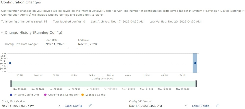
Config Drift
|
This feature is available for all devices.
Displays configuration changes on the device, including a change history, and compares two configuration versions. You can
do these tasks:
-
Label the configuration drift on the time line for future reference. For more information, refer to Label configuration drift.
-
Pick any two versions of the same device and compare their running configuration data.
|
|
REP Rings
|
This tab is available for Cisco Catalyst Industrial Ethernet 3100, 3200, 3300, 3400, 4000, 5000, and 9300 Series Switch. Cisco
Embedded Services 3300 Series Switches (ESS3300), S5200, and S5800.
Displays details about Resilient Ethernet Protocol (REP) rings, such as its name, ring size, first adjacent device, and so
on.
Click Create REP Ring and follow the workflow to create a REP ring.
For more information, refer to Delete a node from a REP ring or Delete a REP ring.
|
|
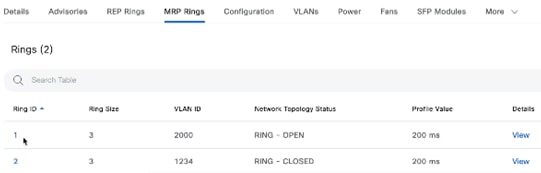
MRP Rings
|
This tab is available only for Cisco Industrial Ethernet (IE) 3000, 4000, 5000 Series Switches.
Displays details about Media Redundancy Protocol (MRP) rings, such as ring ID, ring size, VLAN ID, network topology status,
profile value, and ring details.
To view the MRP ring details from view, click anywhere on the ring.
For more information, refer to MRP ring for nonfabric deployment and View MRP ring status for nonfabric deployment.
|
|
Wireless Info
|
This tab is available only for wireless controllers.
View details about managed sites, wireless settings, redundancy, health parameters, and other information.
In the Wireless Summary tab, in the SSIDs table, you can search for a specific value by clicking Search Table, manually entering a value, and then pressing the Enter key. The narrowed search results display with the value highlighted throughout the table.
|
|
CONFIGURATION
|
This area is available only for wireless controllers.
-
Mobility: This tab displays mobility details, such as the mobility group name, RF group name, and so on.
The Mobility Peers table displays if mobility peers are configured on the device. If mobility peers are not configured, refer to Configure mobility group.
You can filter the table to display specific mobility peers by any combination of values, such as values for MAC address, Device Name, and IP Address fields.
-
Per-Device Configuration: Available only for Cisco Catalyst 9800 Series Wireless Controllers on which this feature is enabled.
For the wireless controller, you can use Per-Device Configuration to manage individual features such as, WLAN configurations, RF configurations, and so on.
|
Note
|
If the wireless controller is provisioned using the intent-based configurations with site-based network profiles, you can only view the device configurations
in this area.
|
For more information, refer to Per-Device Configuration for a Cisco Catalyst 9800 Series Wireless Controller.
|
|
Advisories
|
This tab is available for all devices.
View a device's advisory details in the Advisories table. You can do these tasks:
-
Click Manage All to display the Security Advisories window to manage your devices and advisories.
-
Click Filter to display advisories by any combination of values, such as values for the Advisory ID and Advisory Title fields. Then click Apply.
-
Click an advisory ID to display more information about that advisory.
-
In the Custom Match Pattern column, click Add match pattern to add or update a condition to match with devices in the CONDITIONS text box. Then you can save the match pattern and run a scan to check the number of devices that match with the match pattern.
|
|
Field Notices
|
Displays information about field notices for the device. Refer to View Field Notices.
|
|
Potential Field Notices
|
Displays information about potential field notices for the device.
|
|
Summary
|
This tab is available for all devices.
Displays a device's compliance summary, such as when compliance last ran for the Startup vs Running configuration. You can
do these tasks:
-
Click Run Compliance Check to check the device for compliance.
-
Click View Preference for Acknowledged Violations to view the list of acknowledged violation attributes. You can unlist a violation to open it.
|

 Active
 Expiring
 Expired
 Not Provisioned
 ) for the device.
 ) to switch to the Topology map.
 ).
).

 ) button.
 ) button.
 icon
icon
 icon
icon
 Feedback