Provision SD-Access LISP Fabric Network

Cisco SD-Access zero-trust security solution

Networks need protection against external and internal threats. Cisco SD-Access provides a zero-trust security solution for your workplace. The Cisco SD-Access zero-trust security solution provides secure access to users and devices from all locations across the network.

The Cisco SD-Access zero-trust security solution includes these capabilities:

  • Identify and verify all endpoints: SD-Access establishes an initial level of trust with each connecting endpoint.

  • Establish policy and segmentation: SD-Access ensures least-privilege access based on the endpoint and user type.

  • Continuously monitor endpoints: SD-Access continuously monitors the endpoints to ensure compliance.

  • Threat mitigation: SD-Access allows you to quarantine the endpoints that are noncompliant or exhibit malicious behavior.

The Cisco SD-Access zero-trust security solution provides the flexibility to adopt a path to a zero-trust workplace based on your network settings and services. You can configure how users connect to the network using dynamic rules and automated segmentation.

The Cisco SD-Access zero-trust security solution provides the capability to automate network access policies using these features:

  • Endpoint visibility: You can identify and group endpoints. You can map their interactions through traffic flow analysis and define access policies.

  • Trust monitoring: You can continuously monitor the endpoint behavior, scan for vulnerabilities, verify trustworthiness for continued access, and isolate rogue or compromised endpoints.

  • Network Segmentation: You can enforce group-based access policies and secure network through multilevel segmentation.

The Cisco SD-Access zero-trust security solution enables you to explore various paths to zero-trust workplace based on your network settings and services. You can discover your optimal path based on your current network status, and explore the benefits of each added step on the zero-trust journey.

Zero-Trust Overview dashboard

The SD-Access Zero-Trust Overview dashboard provides an overview of your zero-trust workplace journey. From the main menu, choose Provision > Zero-Trust Overview to view this dashboard.

The zero-trust workplace journey has these phases:

Day-zero view of the Zero-Trust Overview dashboard

Before you start your SD-Access zero-trust workplace journey, the day-zero view of the Zero-Trust Overview dashboard consists of these sections:

The day-zero view of the Zero-Trust Overview dashboard introduces you to Cisco SD-Access, which offers a turnkey, zero-trust solution to automate network access policies. The dashboard displays a diagram of the different pathways to Cisco SD-Access Zero-Trust Workplace based on your network settings and services. When you're done exploring, the dashboard displays two options: either you can start the creation of your network fabric or if you have connectivity, you can start with Endpoint Visibility.
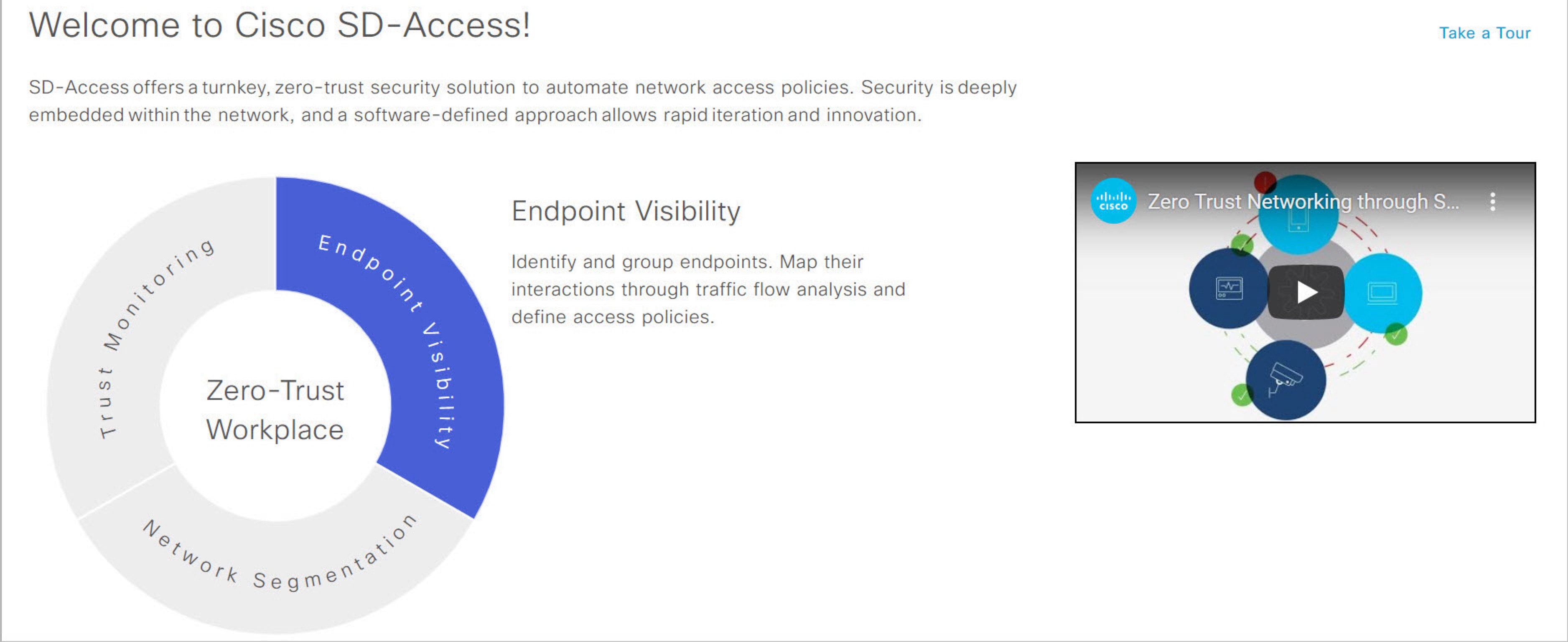
  • Welcome to Cisco SD-Access!: This section consists of an overview video that provides a short overview of the multiple paths towards a full SD-Access zero-trust workplace. It also consists of a circle containing sections for each pillar of the SD-Access zero-trust workplace:

    • Endpoint Visibility

    • Trust Monitoring

    • Network Segmentation

    Hover your cursor over each section to view more information.

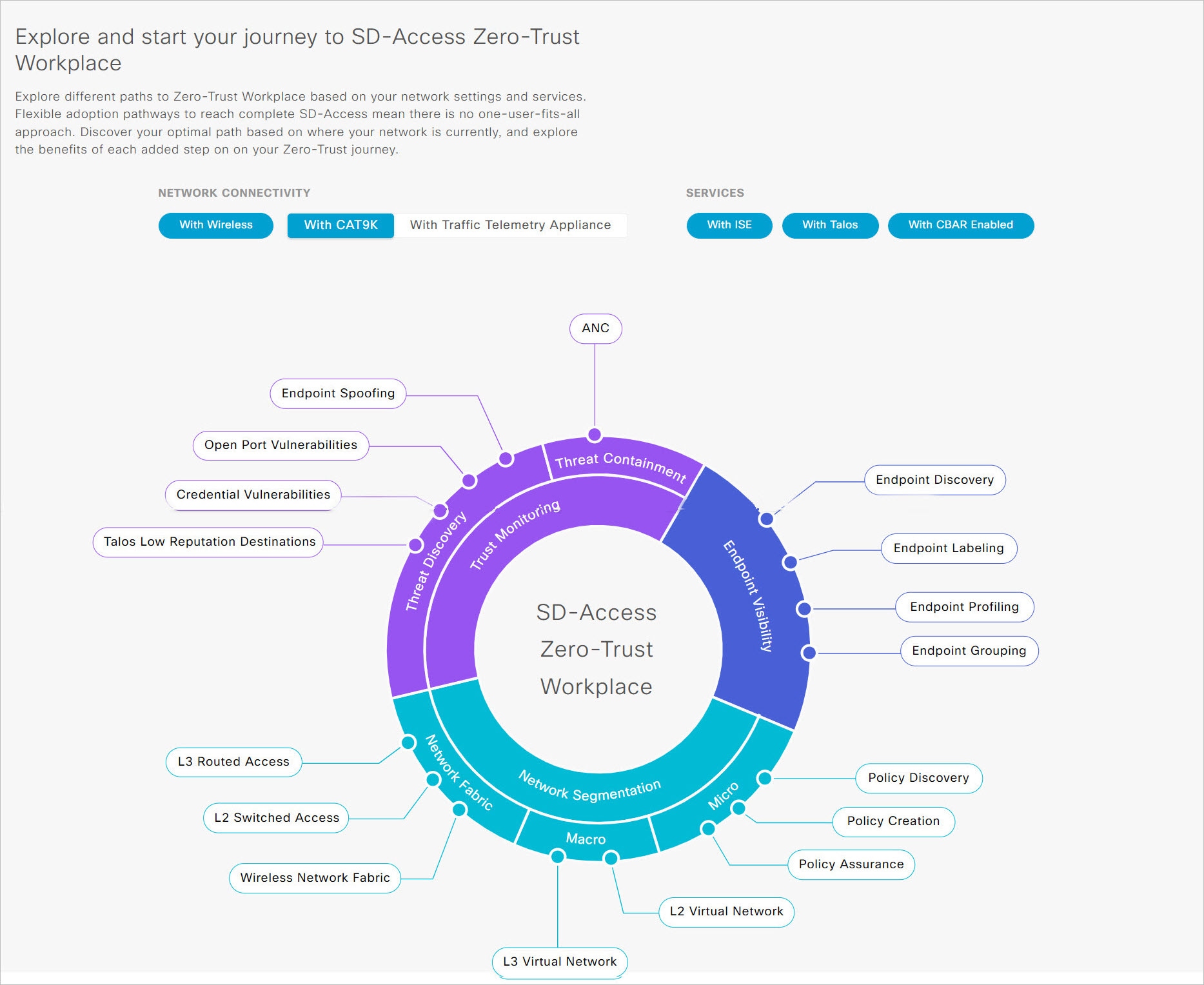
  • Explore and start your journey to SD-Access Zero-Trust Workplace: This section allows you to explore the different paths to a zero-trust workplace based on your network settings and services, and discover the optimal path for your network. This section consists of the Network Connectivity and Services options, and a circular journey map with details about the paths. Based on the options that you choose for network connectivity and services, the journey map displays the available paths to your zero-trust workplace journey.

    To view details about each recommended step in the journey map, hover your cursor over the corresponding step around the journey map.

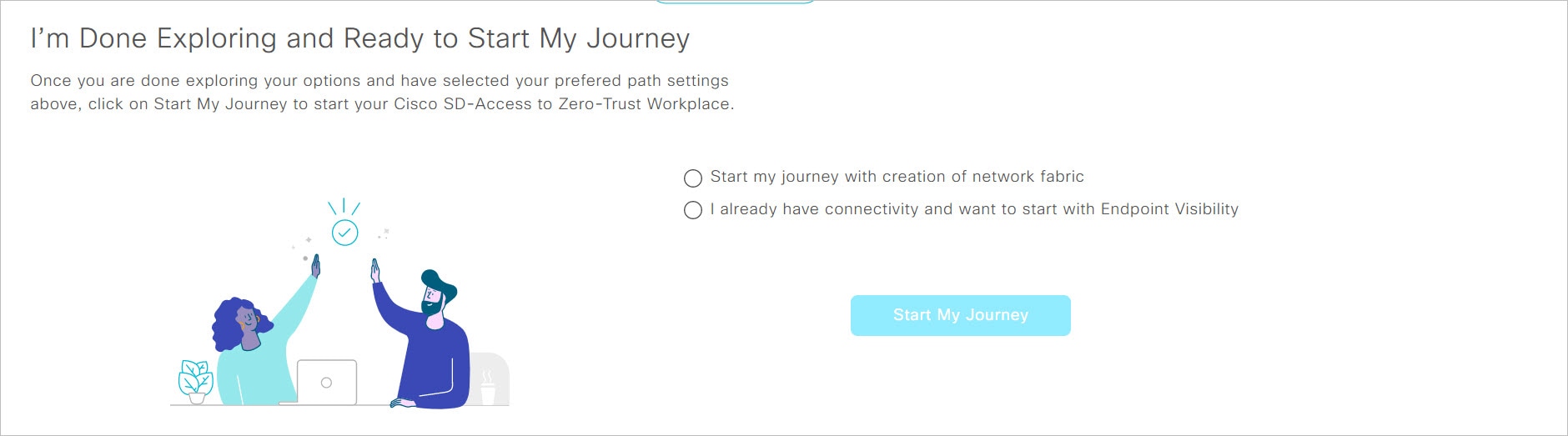
  • I’m Done Exploring and Ready to Start My Journey: After exploring the paths and selecting your preferred settings, use this section to start your journey to a zero-trust workplace.

Get started with SD-Access zero-trust workplace journey

Procedure


Step 1

From the main menu, choose Provision > Zero-Trust Overview.

Step 2

Under Explore and start your journey to SD-Access Zero-Trust Workplace, do these steps:

  1. For Network Connectivity settings, choose the required options:

    • Enable With Wireless to use wireless devices in your zero-trust workplace journey.

    • Enable With CAT9K to use Cisco Catalyst 9000 Series devices or enable With Traffic Telemetry Appliance to use the Catalyst Center Traffic Telemetry Appliance in your zero-trust workplace journey.

  2. For Services settings, choose the required options:

    • Enable With ISE to use Cisco Identity Services Engine in your zero-trust workplace journey.

    • Enable With Talos to use Talos Intelligence in your zero-trust workplace journey.

    • Enable With CBAR Enabled to use Controller-Based Application Recognition (CBAR) in your zero-trust workplace journey.

  3. (Optional) To view details about each recommended step in the journey map, hover your cursor over the corresponding step around the journey map.

Step 3

Under I’m Done Exploring and Ready to Start My Journey, choose one of these options:

  • To create a fabric network and start your journey towards a zero-trust workplace, click Start my journey with creation of network fabric.

  • If you already have fabric network connectivity and want to start your journey towards zero-trust workplace with endpoint visibility, click I already have connectivity and want to start with Endpoint Visibility.

Step 4

Click Start My Journey.

Step 5

In the Modify Journey Map dialog box, do these steps:

  1. Review your journey map settings.

    Note

     
    • Catalyst Center displays a message if it doesn't discover the selected services for your network.

    • Catalyst Center displays a message if it discovers additional services that were not selected in the journey.

  2. (Optional) To remove a selected service from your journey map settings, uncheck the corresponding check box.

  3. Click Confirm.


Day-n view of Zero-Trust Overview dashboard

After starting your SD-Access zero-trust workplace journey, the day-n view of the Zero-Trust Overview dashboard consists of these sections:

Day-n View of the Zero-Trust Overview Dashboard
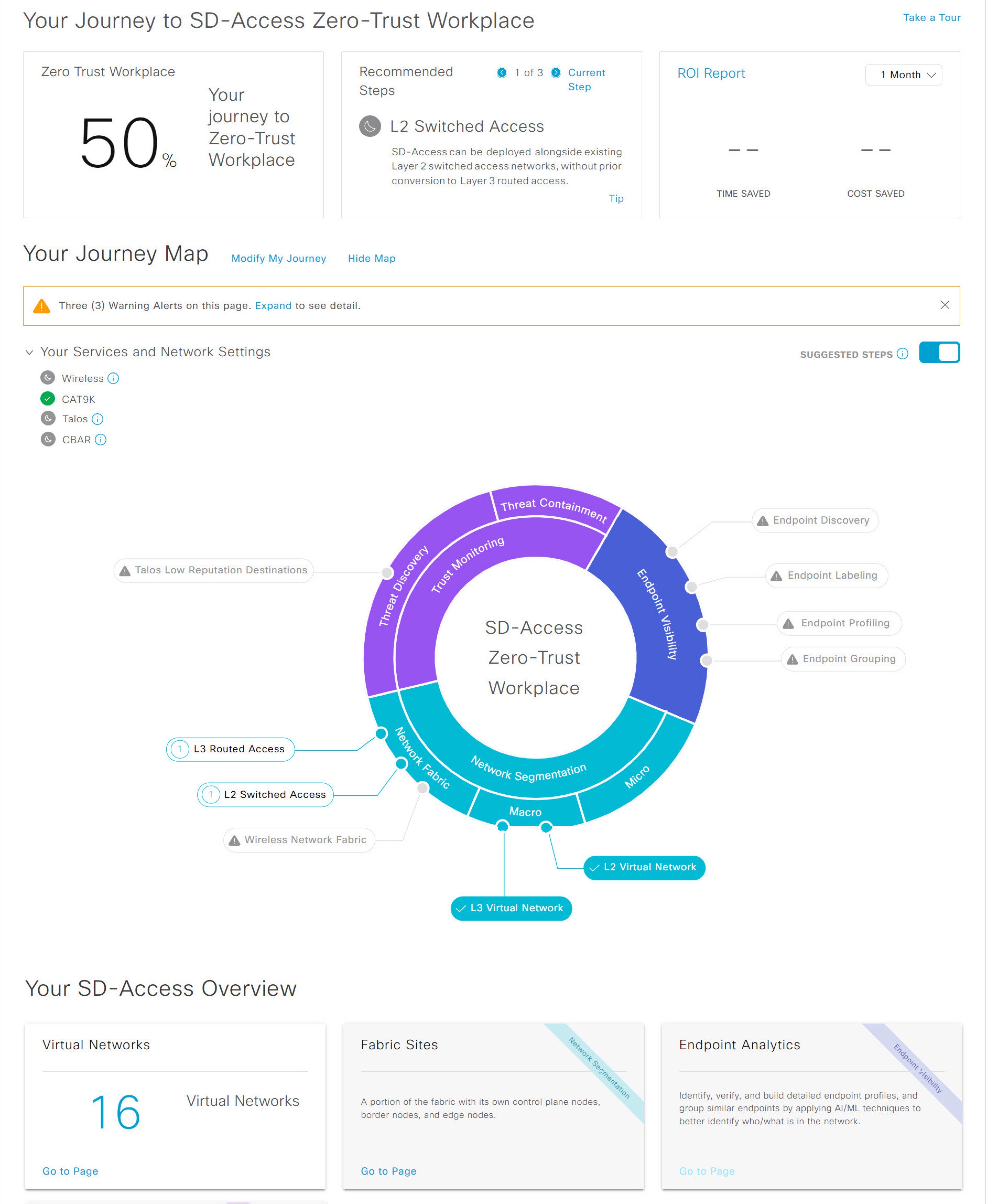
  • Your Journey to SD-Access Zero-Trust Workplace: This section consists of these dashlets:

    • The Zero Trust Workplace dashlet displays the percentage progress of your zero-trust workplace journey.

    • The Recommended Steps dashlet displays the next recommended steps for your zero-trust workplace journey. Use the arrow buttons (Left Arrow and Right Arrow) to scroll through all the steps. This dashlet also displays the tips for some steps. If available, click Tip to view the tips for the corresponding step.

    • The ROI Report dashlet displays the time and cost savings based on the implemented steps as you progress through your zero-trust workplace journey. Use the drop-down in this dashlet to choose the time period for the report. Click ROI Report to view the report.

  • Your Journey Map: This section displays the details of network connectivity and service settings for your zero-trust workplace journey. Click Modify My Journey to modify your zero-trust workplace journey. Click Hide Map to hide the journey map.

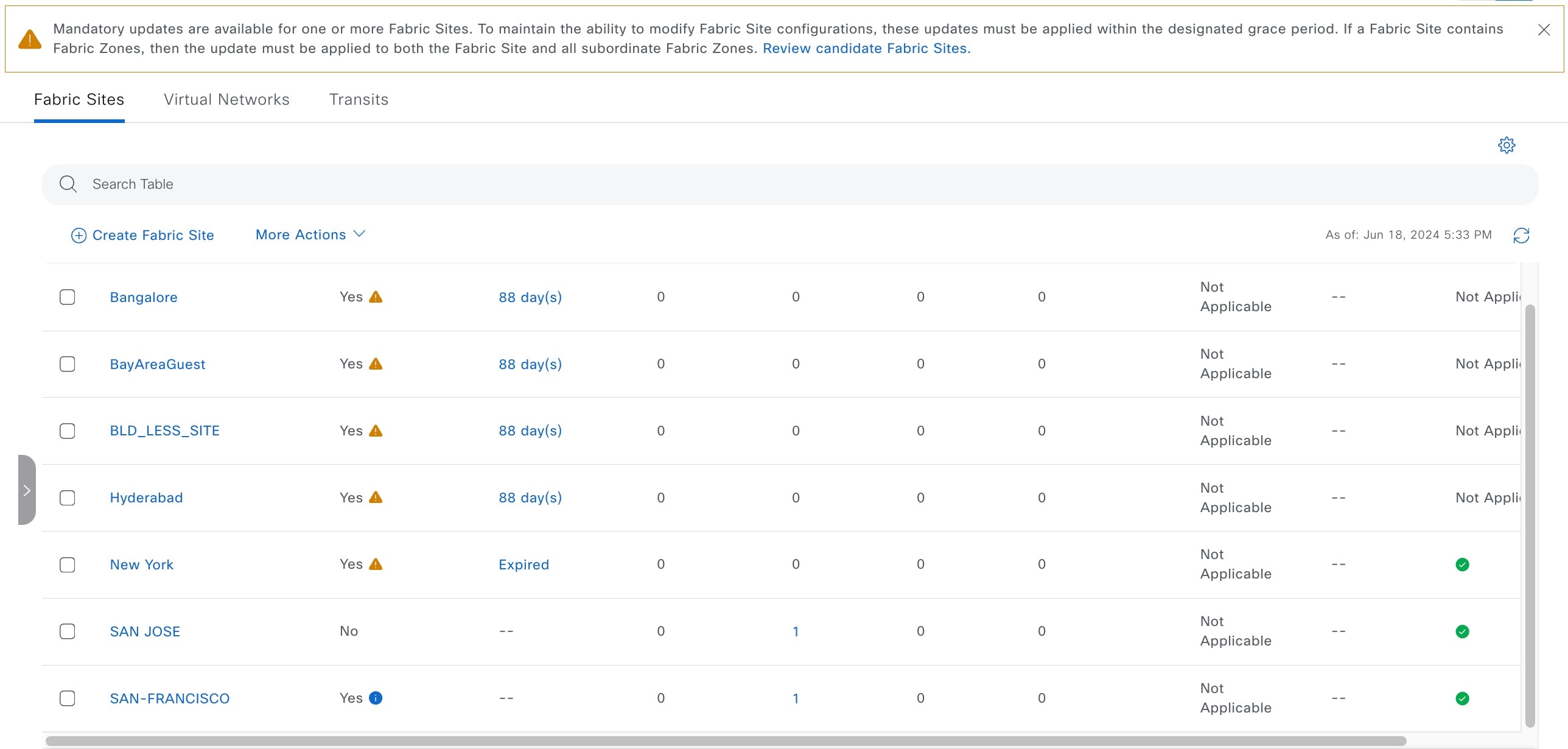
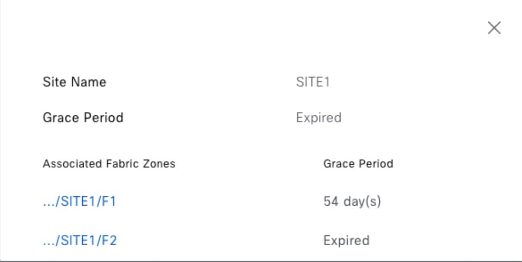
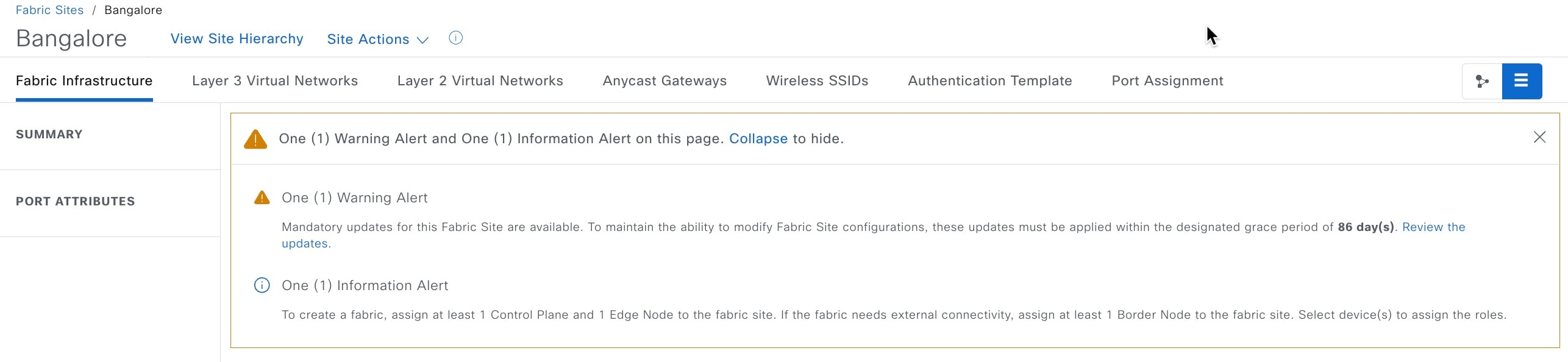
    This section displays the warning alerts for your journey, if available. Click Expand to view the details of the alerts. If a selected service is currently unavailable in your network and you want to remove it from your journey, click the corresponding Remove From Journey option. If you want to get a selected service that is currently unavailable in your network, click the corresponding hyperlink to get the service.

    Expand the Your Services and Network Settings drop-down to view the list of selected services for your journey. The Green Tick Icon icon next to a service indicates that the service is currently available in your network. The Sleep Icon icon next to a service indicates that the service is currently unavailable in your network. Hover your cursor over the corresponding Info Icon icon to view the Update Needed dialog box with details about the unavailable service. In the Update Needed dialog box, do these tasks:

    • To remove the service from your journey, click Remove From Journey.

    • To get the unavailable service in your network, click the corresponding hyperlink.

    Enable the Suggested Steps toggle button to view the suggested order of steps around your journey map.

    To view details about each step in the journey map, hover your cursor over the corresponding step around the journey map.

    The Error Icon icon next to a step indicates that the corresponding configurations are incomplete. A number next to a step (for example, Number Icon) indicates the suggested order of the recommended steps for your journey map. The Tick Icon icon next to a step indicates that the corresponding configurations are complete.

  • Your SD-Access Overview: This section consists of dashlets for each functional area of your zero-trust workplace journey. Click the corresponding Go to Page option to open the relevant window. Each dashlet indicates its corresponding pillar of the zero-trust workplace journey in its upper-right corner.

Modify SD-Access zero-trust workplace journey

Procedure


Step 1

From the main menu, choose Provision > Zero-Trust Overview.

Step 2

Under Your Journey Map, click Modify My Journey.

Step 3

Under Explore and start your journey to SD-Access Zero-Trust Workplace, do these steps:

  1. For Network Connectivity settings, choose the required options:

    • Enable With Wireless to use wireless devices in your zero-trust workplace journey.

    • Enable With CAT9K to use Cisco Catalyst 9000 Series devices or enable With Traffic Telemetry Appliance to use the Catalyst Center Traffic Telemetry Appliance in your zero-trust workplace journey.

  2. For Services settings, choose the required options:

    • Enable With ISE to use Cisco Identity Services Engine in your zero-trust workplace journey.

    • Enable With Talos to use Talos Intelligence in your zero-trust workplace journey.

    • Enable With CBAR Enabled to use Controller-Based Application Recognition (CBAR) in your zero-trust workplace journey.

  3. (Optional) To view details about each recommended step in the journey map, hover your cursor over the corresponding step around the journey map.

Step 4

Under I’m Done Exploring and Ready to Start My Journey, choose one of these options:

  • To create a fabric network and start your journey towards a zero-trust workplace, click Start my journey with creation of network fabric.

  • If you already have fabric network connectivity and want to start your journey towards zero-trust workplace with endpoint visibility, click I already have connectivity and want to start with Endpoint Visibility.

Step 5

Click Modify My Journey.

Step 6

In the Modify Journey Map dialog box, do these steps:

  1. Review your journey map settings.

    Note

     
    • Catalyst Center displays a message if it doesn't discover the selected services for your network.

    • Catalyst Center displays a message if it discovers additional services that were not selected in the journey.

  2. (Optional) To remove a selected service from your journey map settings, uncheck the corresponding check box.

  3. Click Confirm.


About fabric networks

A fabric network is a logical group of devices that is managed as a single entity in one or multiple locations. Having a fabric network in place enables several capabilities, such as the creation of virtual networks and user and device groups, and advanced reporting. Other capabilities include intelligent services for application recognition, traffic analytics, traffic prioritization, and steering for optimum performance and operational effectiveness.

Catalyst Center allows you to add devices to a fabric network. These devices can be configured to act as control plane, border, or edge devices within the fabric network.

Fabric sites

A fabric site is an independent fabric area with a unique set of network devices: control plane, border, edge, wireless controller, ISE PSN. Different levels of redundancy and scale can be designed per site by including local resources: DHCP, AAA, DNS, Internet, and so on.

A fabric site can cover a single physical location, multiple locations, or only a subset of a location:

  • Single location: branch, campus, or metro campus

  • Multiple locations: metro campus + multiple branches

  • Subset of a location: building or area within a campus

A Software-Defined Access fabric network may comprise multiple sites. Each site has the benefits of scale, resiliency, survivability, and mobility. The overall aggregation of fabric sites accommodates a large number of endpoints and scales modularly or horizontally. Multiple fabric sites are interconnected using a transit.

Transits

A transit is a site that interconnects two or more fabric sites or connects the fabric site with external networks (Internet, data center, and so on). There are two types of transit networks:

  • IP transit: Uses a regular IP network to connect to an external network or to connect two or more fabric sites. It leverages a traditional IP-based (VRF-LITE, MPLS) network, which requires remapping of VRFs and SGTs between sites.

  • SD-Access transit: Uses LISP/VxLAN encapsulation to connect two fabric sites. The SD-Access transit area may be defined as a portion of the fabric that has its own control plane nodes, but does not have edge or border nodes. However, it can work with a fabric that has an external border. With an SD-Access transit, an end-to-end policy plane is maintained using SGT group tags.

Fabric readiness, image compatibility, and compliance checks

Fabric readiness checks

Fabric readiness checks are a set of preprovisioning checks done on a device to ensure that the device is ready to be added to the fabric. Fabric readiness checks are now done automatically when the device is provisioned. Interface VLAN and Multi VRF configuration checks are not done as part of fabric readiness checks.

Fabric readiness checks include:

  • Connectivity check: Checks for the necessary connectivity between devices; for example, connectivity from the edge node to map server, from edge node to border, and so on.

  • Existing configuration check: Checks for any configuration on the device that conflicts with the configuration that is pushed through SD-Access and can result in a failure later.

  • Hardware version: Checks if the hardware version of the device is supported.

  • Image type: Checks if the device is running with a supported image type (IOS-XE, IOS, NXOS, Cisco Controller).

  • Loopback interface: Checks for the loopback interface configuration on the device. A device must have a loopback interface numbered 0 with an IP address configured on it to work with the SDA application. Lack of a loopback interface numbered 0 may cause fabric provisioning errors because Loopback0 is used as the routing locator (RLOC) by default.

  • Software license: Checks if the device is running with an appropriate software license.

If an error is detected during any of the fabric readiness checks, an error notification is displayed on the topology area. You can correct the problem and continue with the provisioning workflow for the device.

Image compatibility check

To ensure the network devices (before and after a fabric deployment) are compatible with the recommended or supported software image versions based on the Catalyst Center package version, Catalyst Center performs Image Compatibility check to evaluate the network devices.

If a network device is running an incompatible software image, the red x icon is displayed in the Provision > Inventory > Image Compatibility column. You can check the supported software image versions for your device from the Cisco SD-Access Compatibility Matrix and continue with the provisioning workflow for the device.

Fabric compliance checks

Fabric compliance is a state of a device to operate according to the user intent configured during the fabric provisioning. Fabric compliance checks are triggered based on:

  • Every 24 hours for wired devices and every six hours for wireless devices.

  • When there is a configuration change on the wired device.

    A configuration change on the wired device triggers an SNMP trap, which in turn triggers the compliance check. Ensure that you have configured the Catalyst Center server as an SNMP server.

These compliance checks are done to ensure that the device is fabric compliant:

  • Virtual Network: Checks whether the necessary VRFs are configured on the device to comply with the current state of the user intent for the VN on Catalyst Center.

  • Fabric Role: Checks whether the configuration on the device is compliant with the user intent for a fabric role on Catalyst Center.

  • Segment: Checks the VLAN and SVI configuration for segments.

  • Port Assignment: Checks the interface configuration for the VLAN and authentication profile.

Fabric Health Check

The health of SD-Access application is checked periodically to provide an indication of the application status. SD-Access health check also includes the check for stale database entries in the SD-Access application, which could potentially disrupt fabric provisioning.

You can check the status of SD-Access application on the System > System 360 > System Health page. For more information about how to check the health of an application, see “Use System 360” and “Monitor System Health” in the Cisco Catalyst Center Administrator Guide.

You can also use the Validation Tool to run the same checks by subscribing to the SD-Access Application Health status. Validation Tool is available on the System > System 360 > System Health page. When you run a new validation, ensure that you check the Application Health Status check box under the Validation Set(s) selection field. For more information on how to access and run the Validation Tool, see “Use the Validation Tool” in the Cisco Catalyst Center Administrator Guide.

SD-Access application status can have three values:

  • HEALTHY—Indicates that the SD-Access application is working as expected and all provisioning activities are allowed.

  • UNHEALTHY—Indicates that the SD-Access application is not working due to dependent services not being healthy. This condition may block all provisioning activities in the SD-Access fabric.

  • DEGRADED—Indicates that all dependent services are working but there are database inconsistencies in the SD-Access application. This condition may affect the functioning or provisioning of one or more fabric sites.

    If your SD-Access application is in the DEGRADED state, contact Cisco TAC to resolve the issue.

Fabric scale checks

Scale checks monitor the scale limits or thresholds defined for entities in a fabric site. It provides visibility into the number of fabric entities that are approaching or exceeding the defined scale limits. Scale checks are performed whenever an entity is provisioned in the fabric site.


Note


Scale checks serve as a guideline to provide visibility for potential scale violations and do not impose any enforcement that would prevent the provisioning of additional fabric entities.


You can view the scale check status under the Application Checks column in the Provision > SD-Access > Fabric Sites window. The Application Checks column displays these states based on the scale check results:

  • Critical: Indicates that a fabric entity has exceeded 95% of its defined scale limits.

  • Warning: Indicates that a fabric entity has crossed 75% of its defined scale limits.

  • Green check mark: Indicates that there are no issues with the SD-Access application.

  • Not Applicable: Indicates that there are no entities associated with the fabric site.

For Critical and Warning status, you can click the indicator to view more information on the scale checks.

For information on scale thresholds per fabric site, see "Appliance scale" in Cisco Catalyst Center Data Sheet.

Fabric site updates

The Fabric Sites overview page provides information on the configuration updates available for the fabric sites and the grace period to apply these updates. It displays a banner message to apply the mandatory configuration updates available for the sites within a designated grace period. If the grace period expires (by default, 180 days), no configurations on the fabric site can be done until the updates are applied. You can click the Review candidate Fabric Sites link in the banner to view the fabric sites that need mandatory updates.

Columns in the Fabric Sites table display the configuration update information, including:

  • Outstanding Updates: Displays Yes or No based on the updates available for the site and its associated zones.

  • Update Grace Period: Displays the least time left (number of days) among the fabric site and its associated zones to apply the updates. You can click the value to view the individual grace period for the site and its associated zones.

Fabric Site Configuration Updates

View Grace Period for Sites and Zones

This table describes the values displayed in these columns.

Outstanding updates

Update grace period

Description

Yes with an info icon.

Displays a blank value.

Indicates that the updates are available but the prerequisites have not been met and hence there is no timer for applying the updates. The grace period timer starts once the prerequisites are met and the updates are ready to be applied.

Yes with a warning icon.

Displays the least time left (number of days) among the fabric site and its associated zones to apply the updates. If the grace period has expired for a site or any of its associated zones, the column displays Expired.

Indicates that the site or its associated zones have outstanding updates. Click the value to view the individual grace period for the site and its associated zones.

No

Displays a blank value.

Indicates that there are no outstanding updates for the site and its associated zones.

When you click on a site with an outstanding update, the fabric site window displays alerts for the configuration update based on the availability of updates and the grace period, as follows:

  • Ready updates with active grace period: Displays a warning pop-up window and an alert about the availability of updates and the grace period to apply the updates.

  • Ready updates with expired grace period: Displays an error pop-up window and a critical alert that the grace period for the updates has expired and all fabric site configurations are suspended.

  • Not ready updates: Displays an information alert that the updates for the site are available but the prerequisites have not been met. You can review the available updates and prepare for implementation.

In the alert dialog box, click Expand to view the alert details and click the Review the updates link to view and apply the available updates.

Role-based access control for Cisco SD-Access

Role-based access control in Catalyst Center allows you to create custom roles, which define the capabilities and the permissions that a user has access to. For Cisco SD-Access, Catalyst Center supports the creation of a custom role with the SD-Access capability that

  • simplifies the role-based access control configuration for Cisco SD-Access fabric.

  • allows users assigned with the custom role to create and manage an SD-Access fabric, and

  • avoids manual configuration of access permissions for dependant functionalities. When you set the access permissions for SD-Access, all the other dependent capabilities such as device discovery, device provision, PnP, compliance, and SWIM are automatically selected with the necessary permissions. It is recommended not to reconfigure these permissions manually.

For more information on configuring custom roles in Catalyst Center, see Cisco Catalyst Center Administrator Guide.

Add a fabric site

Before you begin

You can create a fabric site only if IP Device Tracking (IPDT) is already configured for the site.

Procedure


Step 1

From the main menu, choose Provision > Fabric Sites.

Step 2

Under SUMMARY, click the number that indicates the count of the fabric sites.

The resulting window displays every fabric site that has already been created and its information (such as Health Score, Fabric Zones, Fabric Devices, Fabric Roles, and Connected Transits) in a tabular format.

You can customize the table view to display only selected columns. Use the gear icon at the top right corner of the window to edit the Table Settings and Apply the changes.

Step 3

Click Create Fabric Sites.

Alternatively, instead of the first three steps, click the menu icon and choose Workflow > Create Fabric Sites and Fabric Zones.

Step 4

In the Create Fabric Sites window, click Let’s Do it to go directly to the workflow.

Step 5

In the Fabric Site Location window, select an area, building, or floor to add as a fabric site.

Step 6

In the Wired Endpoint Data Collection window, ensure that the Wired Endpoint Data Collection check box is checked.

Step 7

In the Authentication Template window, do these steps:

  1. Select an authentication template for the fabric site:

    Template option

    Description

    Closed Authentication

    Any traffic before authentication is dropped, including DHCP, DNS, and ARP.

    Open Authentication

    A host is allowed network access without having to go through 802.1X authentication.

    Low Impact

    Security is added by applying an ACL to the switch port, to allow very limited network access before authentication. After a host has been successfully authenticated, additional network access is granted.

    None

    None.

  2. (Optional) If you select Closed Authentication, Open Authentication, or Low Impact, click Edit to edit the authentication settings:

    Setting

    Task

    First Authentication Method

    Select 802.1x or MAC Authentication Bypass (MAB).

    802.1x Timeout (in seconds)

    Use the slider to specify the 802.1x timeout, in seconds.

    Wake on LAN

    Select Yes or No.

    Number of Hosts

    Select Unlimited or Single.

    BPDU Guard

    Use this check box to enable or disable the Bridge Protocol Data Unit (BPDU) guard on all the Closed Authentication ports.

    Pre-Authentication Access Control List​

    1. Enable the toggle button to configure preauthentication control for Low Impact authentication.

    2. From the Implicit Action drop-down list, choose an implicit action and enter a description for the rule.

    3. To add an access contract, click Add Contract Action, choose the rules, and click Apply Table.

Step 8

(Optional) In the Fabric Zones window, choose one of these options:

Option

Task

To designate fabric zones later

Click Setup Fabric Zones Later.

To designate fabric zones and create scoped subnets

Click Setup Fabric Zones Now and select a fabric site from the displayed network hierarchy.

Step 9

In the Summary window, review the fabric site settings.

You can edit any of the fabric site or zone settings here.

Step 10

Schedule the task for deployment.

Depending on Visibility and Control of Configurations settings, you can either:

Step 11

On the Tasks window, monitor the task deployment.

Step 12

It takes a few seconds for the site and zones to be provisioned. Upon successful creation of the site, a Fabric Site Creation Completed message displays.

Next, you are provided with options to either create a new fabric site or view the activities on the Tasks window.


Move a fabric site

After creating a fabric site, you can change the site hierarchy in these ways:

  • A fabric site can't be moved under another fabric site; nesting of fabric sites isn't permitted.

  • Once a site, building, or floor is part of a fabric site (either as a fabric zone or as a member in the fabric site), it must remain within that fabric site's hierarchy. It can't be moved outside of it.

  • To prevent conflicts during a move, the system verifies that network settings and network profiles match between the current and new parent sites.

Figure 1. Sample site hierarchy
Table 1. Sample site move operations

Move operation

Allowed?

Reason

Move site India to new site Asia created under Global

Yes

You can move the site because the new parent or new ancestors are not fabric sites

Move site India under existing fabric site USA

No

You can't move a site under a new fabric site

Move building BGL-B1 to USA

No

You can't move a building from one fabric site to another

Move building BGL-B1 to new site Asia created under Global

No

You can't move a building out of a fabric site

Move floor Floor1 to a new building BGL-B2 within existing fabric site

Yes

You can move a zone within its fabric site

Move floor Floor1 to a new building SJ-B1 in a different fabric site

No

You can't move a zone to a different fabric site

Move building BGL-B1 to Bangalore

Yes

You can move a building within the India fabric site

Configure a fabric site

After you create a fabric site, you can configure the devices, virtual networks, and authentication methods for the hosts to connect to a fabric site.

Select a fabric site under the Provision > SD-Access > Fabric Sites menu and use these tabs:

  • Fabric Infrastructure: Assign devices to fabric roles.

  • Layer 3 Virtual Networks: Create a Layer 3 virtual network for the fabric site or assign an existing Layer 3 virtual network to the fabric site.

  • Layer 2 Virtual Networks: Create a Layer 2 virtual network for the fabric site or assign an existing Layer 2 virtual network to the fabric site.

  • Anycast Gateways: Create an Anycast Gateway for a Layer 3 virtual network in the fabric site.

  • Authentication Template: Select an authentication template for the fabric.

  • Wireless SSIDs: Specify wireless SSIDs within the network that hosts can access. You can select the guest or enterprise SSIDs and assign address pools.

  • Port Assignment: Apply specific configurations to each port, depending on the type of device that connects to the fabric site.

    Each of these operations is explained in the later sections.


    Note


    Constraints include:

    • Cisco SD-Access deployments support only APs, extended nodes, user devices (such as a single computer or a single computer plus phone), and devices that need trunk ports, such as single servers.

    • Servers with internal switches or virtual switches aren't supported.

    • Other networking equipment (such as hubs, routers, or switches) isn't supported.


Add a device to a fabric

After you have created a fabric site, you can add devices to the fabric site. You can also specify whether the device should act as a control plane node, an edge node, or a border node.

You can add a new device to the fabric site only if IP Device Tracking (IPDT) is configured for the fabric site.

A device that is assigned the Access role and has been provisioned before enabling IPDT on the site can’t be added to the fabric. Reprovision such devices before adding them to the fabric site. Check the Provision workflow to confirm the status of Deployment of IPDT on the device.


Note


  • It’s optional to designate the devices in a fabric site as control plane nodes or border nodes. You might have devices that don’t occupy these roles. However, every fabric site must have at least one control plane node device and one border node device. In the current release for wired fabric, you can add up to six control plane nodes for redundancy.

  • Currently, the Cisco Wireless Controller communicates only with two control plane nodes.

  • You cannot change a device's role after it is added to the fabric. To change the role, remove the device from the fabric and re-add it.


Before you begin

Provision the device if you haven’t already provisioned it:

  • The Provision > Network Devices > Inventory window displays the discovered devices.

  • The topology view shows a device in gray if it has passed the fabric readiness checks and is ready to be provisioned.

  • If an error is detected during any of the fabric readiness checks, an error notification is displayed on the topology area. Click See more details to check the problem area listed in the resulting window. Correct the problem and click Re-check to ensure that the problem is resolved.

  • If you update the device configuration as a part of problem resolution, ensure that you resynchronize the device information by doing an Inventory > Resync for the device.


Note


You can continue to provision a device that has failed the fabric readiness checks.


Procedure


Step 1

From the main menu, choose Provision > Fabric Sites.

Step 2

Under SUMMARY, click the number that indicates the count of fabric sites.

Step 3

Select the fabric site to add a device.

The resulting topology view displays all devices in the network that have been inventoried. In the topology view, any device that is added to the fabric is shown in blue.

Step 4

From the List view under the Fabric Infrastructure tab, click a device. A slide-in pane displays these Fabric options:

Option Description

Edge Node

Toggle the button next to this option to enable the selected device as an edge node.

Border Node

Toggle the button next to this option to enable the selected device as a border node.

Control Plane Node

Toggle the button next to this option to enable the selected device as a control plane node.

To configure a device as a fabric-in-a-box, select the Control Plane Node, Border Node, and Edge Node options.

To configure the device as a control plane and a border node, select both Control Plane Node and Border Node.

Step 5

(Optional) To enable the wireless capability for the device, under Capability, click the Embedded Wireless LAN Controller toggle button and do these steps:

Alternatively, if the toggle button is already enabled, you can click Configure to configure the wireless settings.
  1. If you have not installed the wireless package on the device yet, Catalyst Center displays a warning message indicating that the embedded wireless controller software image is necessary for enabling the capability. In the warning dialog box, click OK to install the image manually.

  2. Under Download Image, click Choose File to navigate to a software image stored locally, or Enter image URL to specify an HTTP or FTP source from which to import the software image.

  3. Click Import.

    The progress of the image import is displayed. To exit the window, and view the progress of the import and schedule the installation later, click Close.

  4. After the image import is complete, under Schedule Image Installation on Download Image, choose one of these options:

    • Now: Immediately install the image.

    • Later: Schedule the image installation for a later date or time.

  5. In the Task Name field, update the task name, if required.

  6. If you chose Later, do these tasks:

    • Under Start Date/Time, specify a start date and time for the image installation.

    • To use the default site time zone for the image installation, check the Site Settings check box. To select a time zone, uncheck the Site Settings check box and choose a time zone from the drop-down list.

  7. Click Apply.

    To view the status of image installation, go to the Activities > Tasks window and open the relevant work item. After the software image is distributed and activated on the switch, you must resynchronize the device using the Provision > Inventory > Resync option.

  8. Under Manage Scope, do these tasks:

    • Under the Primary tab, check the check box next to the required site name.

    • Under the Secondary tab, check the check box next to the required site name.

    You can select either a parent site or individual sites. If you select a parent site, all the children under the parent site are also selected. You can uncheck the check box to deselect an individual site.

    You can also use the Search Hierarchy search field or the filter icon to find a site.

  9. Click Next.

  10. Under Advanced, to enable the Rolling AP Upgrade feature, check the Enable check box.

    (Optional) If you check this check box, from the AP Reboot Percentage drop-down list, choose a percentage.

  11. Click Next.

  12. Under Summary, review the configuration settings.

  13. Click Save.

If the wireless capability is enabled for a device and there are changes in the wireless network settings, to push the changes to the device, you must click Configure and save the configuration.

Step 6

Click Add to save the configurations.

Step 7

Click Deploy under the Fabric Infrastructure tab to configure the device.

Step 8

Schedule the task for deployment.

Depending on Visibility and Control of Configurations settings, you can either:

Note


A device is added to the fabric only if the device runs a software release that is compatible with the Catalyst Center release. For information about fabric device compatibility, see Cisco SD-Access Compatibility Matrix.

For a given fabric role, if the software image on the device isn’t compatible with the Catalyst Center release, the device isn’t added to the fabric and an error message is displayed.

Step 9

On the Tasks window, monitor the task deployment.


What to do next

After a device is added to the fabric, fabric compliance checks are automatically performed to ensure that the device is fabric-compliant. The topology displays a device that has failed the fabric compliance check in blue color with a cross-mark beside it. Click See more details on the error notification to identify the problem area and correct it.

Remove a device from a fabric

Use this procedure to remove one or more devices from a fabric site.

Procedure


Step 1

From the main menu, choose Provision > Fabric Sites.

Step 2

In the Fabric Sites tab, under SUMMARY, click the number that indicates the count of fabric sites.

Step 3

In the Fabric Sites window, choose the fabric site.

Step 4

From the List view under the Fabric Infrastructure tab, choose a device which is part of the fabric (has a Fabric Role) by

  • clicking the device name, or

  • checking the check box next to the device and choosing More Actions > Edit Fabric Role. You can choose multiple devices.

In the topology view, any device that is added to the fabric is shown in blue.

Step 5

In the slide-in pane, under the Fabric tab, click Remove From Fabric.

Step 6

Schedule the task for deployment.

Depending on Visibility and Control of Configurations settings, you can either:

Step 7

On the Tasks window, monitor the task deployment.


Add a device as a border node

When you add a device to a fabric, you can add it in various combinations to act as a control plane node, border node, or edge node, as described in Add a device to a fabric.

This section describes how to add a device as a border node and do these configurations:

  • Border node type: Internal, External, or Internal and External (Step 9)

  • Border node Priority (Step 10)

  • Border node Affinity-ID (Step 10)

  • TCP MSS Adjustment value on the border node switched virtual interfaces (SVIs) (Step 10)

  • AS Path Prepend (Step 10)

  • Associated transit: SD-Access transit or IP-based transit (Step 11)

  • IP address pool allocation for Layer 3 handoff (Step 11)

Before you begin

To use the Border Node Affinity-ID feature, ensure that you create an SD-Access LISP Pub/Sub transit. For more information, see Create an SD-Access transit. When adding the first control plane node in the local fabric site, ensure that you select the LISP Pub/Sub control plane protocol. For more information, see Configure LISP Pub/Sub. The border node must be running Cisco IOS XE Release 17.8.1 or later.

Procedure


Step 1

From the main menu, choose Provision > Fabric Sites.

Step 2

In the Fabric Sites tab, under SUMMARY, click the number that indicates the count of fabric sites.

Step 3

In the Fabric Sites window, select the fabric site to configure a border node.

The resulting topology view displays all the devices in the network inventory. In the topology view, any device that is operating in a fabric role is shown in blue.

Step 4

Under the Fabric Infrastructure tab, click a device.

Step 5

In the slide-in pane, click the Border Node toggle button.

Step 6

In the resulting slide-in pane, click the Layer 3 Handoff tab.

Step 7

Check the Enable Layer 3 Handoff check box.

Step 8

Enter the Local Autonomous Number for the device.

If the local autonomous number is already configured on the device, this field displays the configured number and is disabled. You cannot change the local autonomous number if it’s already configured on the device.

Step 9

Configure the type of border node. By default, a border node is designated as an external border node, wherein it acts as the default gateway to the fabric site, without importing any external routes.

A border node can be configured to be an internal border node, wherein it isn’t the default gateway and only imports external routes. A border node can also have a combined role of internal and external borders.

  • Check both the Default to all virtual networks and Do not import external routes check boxes to designate the border as an external border node.

  • Uncheck both the Default to all virtual networks and Do not import external routes check boxes to designate the border as an internal border node.

  • Check the Default to all virtual networks check box to designate the border node as an external and internal border. It acts as the fabric default gateway and also imports BGP-learned routes into the fabric site. (Don’t check the Do not import external routes check box.)

For information about border node types, see the Cisco SD-Access Solution Design Guide.

Step 10

To configure the border node priority, affinity-ID, AS Path Prepend, TCP MSS adjustment and native multicast across SD-Access transit, click Advanced and do this configuration:

  1. To change the border node priority, check the Modify Border Priority check box and enter a new priority value.

    • Priority value ranges from 1 to 10.

    • 1 indicates the highest priority.

    • 10 indicates the lowest priority.

    • The default priority value is 10.

    If two or more border nodes are configured in a fabric site, traffic is routed through the border node that has a higher priority. If the priority values are the same, traffic is load balanced across the border nodes.

  2. (Optional) To configure the border node affinity-ID, check the Modify Border Node Affinity-ID check box and enter values for these fields:

    • Affinity-ID Prime: A lower relative prime value indicates a higher preference.

    • Affinity-ID Decider: When the prime value is the same for two border nodes, the decider value is used as a tie-breaker to determine the border node preference.

    Affinity-ID is a relative value, considering the value of this border node among the received values from all the other available border nodes. The lower the relative value of affinity-ID, the higher the preference for a destination border node. By default, the affinity-ID value isn’t provisioned.

    When the received affinity-ID values are equal, priority is used to determine the border node preference.

    Note


    For proper functionality of the Affinity-ID feature, ensure that you configure an affinity-ID on all border nodes connected to the same SD-Access transit.

  3. To define the number of AS Path prepends to the BGP AS_PATH list, check the AS Path Prepending check box and enter a value between 1 to 10.

    AS Path prepending helps you to choose the ingress border.

  4. To customize the TCP maximum segment size (MSS) value for the Layer 3 handoff SVIs, check the TCP MSS Adjustment check box and input the required value.

    The TCP MSS Adjustment value can range from 500 to 1440. TCP MSS Adjustment value is applicable for the TCP sessions over both IPv4 and IPv6.

    Note


    You can customize the TCP MSS value only if the border device is configured for Layer 3 handoff.

  5. (Optional) To configure native multicast over multiple sites that are connected to an SD-Access transit, check the Enable Multicast over SD-Access Transit check box.

    Note


    Ensure that you enable a similar check box for the SD-Access transit too.

    You can view the border node priority and affinity-ID deployment logs in Activities > Audit Logs.

Step 11

Hover your cursor over Add Transit Site and select a transit that will be connected to this border node.

In an IP:BGP IP TRANSIT, you can choose to either automate the IP address allocation for a virtual network or manually assign the Local and Peer IP addresses for a virtual network. You cannot do both.

  1. (Optional) To enable Catalyst Center to allocate IP address for the connection between the border node and peer, choose an IP address pool from the Select IP Address Pool drop-down list.

    Note


    Select IP Address Pool is disabled if you have manually assigned the Local and Peer IP addresses.

  2. To configure the handoff interface, click Add External Interface.

    Do these steps in the resulting window:

    1. Select an interface from the External Interface drop-down.

    2. The Remote AS Number is automatically derived from the selected Transit or Peer network.

    3. (Optional) Enter the a description for the interface in the Interface Description field.

    4. (Optional) From the Actions drop-down list, choose Enable All or Disable All.

    5. Click the Enable Layer 3 Handoff toggle button for the virtual network. This virtual network is advertised by the border node to the peer through BGP. You can select one, multiple, or all virtual networks.

    6. In the VLAN ID field, enter an ID for the selected virtual network.

    7. (Optional) To manually assign the IPv4 and IPv6 Local IP Address and Peer IP Address for the selected virtual network, enter the IP addresses and subnet mask in the CIDR notation (IP address/prefix-length).

      Note


      The Local IP Address and Peer IP Address fields are disabled if you have already selected an IP Pool.

    8. Click Save.

  3. Click Add.

Step 12

(Optional) Perform this step only if you are connecting a traditional network to the fabric site or you are migrating from a traditional network to an SD-Access network. Click the Layer 2 Handoff tab.

A list of virtual networks and the count of IP address pools in each virtual network displays.

  1. Click a virtual network that is to be handed off.

    A list of IP address pools that are present in the virtual network and a list of interfaces through which you can connect to the traditional network displays.

  2. From the External Interface drop-down, choose an interface.

  3. Under Interface Description, enter an optional description for the interface.

  4. In the External VLAN field, enter the VLAN number into which the fabric must be extended.

    A virtual network can be handed off on a single interface or on multiple interfaces. Layer 2 handoff for a segment can also be done on two different devices. In both cases, ensure that no loops are formed in the network.

    Because a border node is connected to the traditional network, it is subject to broadcast storms, Layer 2 loops, and spanning-tree problems that can occur in Layer 2 switched access networks. To prevent disruption of control plane node services or border node services connecting to other external networks, a border node should be dedicated to the Layer 2 handoff feature and not colocated with other fabric roles or services.

  5. Click Save.

Step 13

Click Add to save the configurations.

Step 14

Click Deploy under the Fabric Infrastructure tab to configure the border node.

Depending on Visibility and Control of Configurations settings, you can either:

Note


A device is configured as a border node only if the device runs a software release that is compatible with the Catalyst Center release. If the device runs an incompatible software, an error message is displayed and the device is not configured as a fabric border node. For information about software compatibility, see the Cisco SD-Access Compatibility Matrix.

Step 15

On the Tasks window, monitor the task deployment.


Configure LISP Pub/Sub

You can configure LISP Pub/Sub on a fabric site only when you add the first control plane to your fabric.

Before you begin

Ensure that the fabric devices operate on Cisco IOS XE Release 17.6.1 or later.

Procedure


Step 1

From the main menu, choose Provision > Fabric Sites.

Step 2

Under SUMMARY, click the number that indicates the count of fabric sites.

Step 3

Choose the fabric site to add a device.

The resulting topology view displays all devices in the network that have been inventoried. In the topology view, any device that is added to the fabric is shown in blue.

Step 4

From the List view under the Fabric Infrastructure tab, click a device that is to be configured as a control plane.

Step 5

In the slide-in pane, enable the Control Plane Node toggle button to configure this plane.

Step 6

In the Configure Control Plane slide-in pane, choose LISP Pub/Sub route distribution protocol and click Add.

Step 7

Click Deploy under the Fabric Infrastructure tab to configure the LISP Pub/Sub Control Plane.

Depending on Visibility and Control of Configurations settings, you can either:

Step 8

On the Tasks window, monitor the task deployment.

Step 9

To verify the configuration of LISP Pub/Sub in the fabric site, see the LISP Pub/Sub status on the SITE SUMMARY window.


Reconfigure a fabric

If you modify an IP address pool that is used in a fabric, the fabric becomes outdated. Use this procedure to update the fabric to configure the IP address pool changes to the devices in the fabric site.

The time taken to the reconfigure the fabric depends on the number of devices.


Note


You can't perform other operations on the fabric devices until the fabric is reconfigured to update the devices with the IP address pool changes.


Procedure


Step 1

From the main menu, choose Provision > Fabric Sites.

Step 2

In the Fabric Sites tab, under SUMMARY, click the number that indicates the count of fabric sites.

Step 3

In the Fabric Sites window, select the fabric site that uses the modified IP address pools.

Step 4

In the Fabric Infrastructure tab, under the warning alert, click Reconfigure Fabric.

Depending on Visibility and Control of Configurations settings, you can either:

Step 5

On the Tasks window, monitor the task deployment.


Create an IP transit

Use this procedure to create an IP transit.

Procedure


Step 1

From the main menu, choose Workflows > Create Transits.

Alternatively, you can navigate to Provision > Transits, and click Create Transit.

Step 2

If a task overview window appears, click Let's Do It to go directly to the workflow.

Step 3

In the Transit Name and Type window, do these steps:

  1. In the Transit Name field, enter a name for the transit.

  2. From the Transit Type drop-down list, choose IP-Based.

    The routing protocol is set to BGP by default.

  3. In the Remote BGP Autonomous System Number field, enter the Autonomous System Number (ASN) for the transit.

  4. In the Select Site drop-down list, choose a site for the transit.

    Ensure that the chosen site is at the fabric site level or above it.

    You can edit the site mapping after creating the transit. To edit, in the Transits window, click More Actions > Edit Transit and update the site selection as required.

    If the transit is...

    Then...

    associated with fabric sites

    choose a site that is a common parent for all the associated fabric sites.

    not associated with fabric sites

    you can choose any site that is at a level of a fabric site or above it.

Step 4

In the Transit Control Plane Nodes window, click Next.

Step 5

In the Summary window, review the configuration settings. (To make any changes, click Edit.)

Step 6

Schedule the task for deployment.

Depending on Visibility and Control of Configurations settings, you can either:

Step 7

On the Tasks window, monitor the task deployment.


Create an SD-Access transit

Use this procedure to create an SD-Access transit.

Procedure


Step 1

From the main menu, choose Workflows > Create Transits.

Alternatively, you can navigate to Provision > Transits, and click Create Transit.

Step 2

If a task overview window appears, click Let's Do It to go directly to the workflow.

Step 3

In the Transit Name and Type window, do these steps:

  1. In the Transit Name field, enter a name for the transit.

  2. From the Transit Type drop-down list, choose a transit type.

    • To configure a transit for the fabric sites that don’t have a LISP Pub/Sub control plane, choose SD-Access (LISP/BGP).

    • To configure a transit for the fabric sites that have a LISP Pub/Sub control plane, choose SD-Access (LISP Pub/Sub).

      If you choose this option, to enable native multicast over the transit, check the Native Multicast Over SD-Access Transit check box.

      Note


      To complete the native multicast configuration over multiple sites that are connected to the SD-Access transit, ensure that you enable multicast over SD-Access transit on the border nodes.

      To share the SD-Access (LISP Pub/Sub) transit with other Catalyst Center clusters, choose Yes, Share. Otherwise, choose No, keep it local.

      Note


      The Yes, Share option is visible only if the Multiple Catalyst Center package is installed on all the Catalyst Center clusters.

  3. In the Select Site drop-down list, choose a site for the transit.

    Ensure that the chosen site is at a level above the fabric site.

    You can edit the site mapping after creating the transit. To edit, in the Transits window, click More Actions > Edit Transit and update the site selection as required.

    If the transit is...

    Then...

    associated with fabric sites

    choose a site that is a common parent for all the associated fabric sites and the associated transit control plane nodes.

    not associated with fabric sites

    you can choose any site that is a common parent for the associated transit control plane nodes.

Step 4

In the Transit Control Plane Nodes window, do these steps:

  1. From the Select a Site drop-down list, choose a site with a control plane node.

    Note


    You can’t add an SD-Access (LISP Pub/Sub) transit to a fabric site that uses the LISP/BGP control plane. You can’t add SD-Access (LISP/BGP) transit to a fabric site that uses the LISP Pub/Sub control plane.

  2. From the Transit Control Plane Node drop-down list, choose a control plane node.

  3. (Optional) To configure an additional node, click the plus icon (plus icon) and repeat 4.a and 4.b.

Step 5

In the Summary window, review the configuration settings. (To make any changes, click Edit.)

Step 6

Schedule the task for deployment.

Depending on Visibility and Control of Configurations settings, you can either:

Step 7

On the Tasks window, monitor the task deployment.


What to do next

To interconnect the fabric sites with an SD-Access transit, add the transit to the fabric border node.

Configure an authentication template for the fabric site

Use this procedure to configure an authentication template that applies to all devices in the fabric site.


Note


If one or more stack members or line cards are added on any of the existing switches in the fabric, a warning alert is displayed to configure the authentication template on these new stack members or line cards as well. Click Apply Fix in the warning alert to apply the configurations and update the fabric.


Procedure


Step 1

From the main menu, choose Provision > Fabric Sites.

Step 2

Under SUMMARY, click the number that indicates the count of fabric sites.

Step 3

Click a fabric site.

Step 4

Click the Authentication Template tab.

Step 5

Under Select Authentication Template, choose an authentication template for the site.

  • Open Authentication: A host is allowed network access without having to go through 802.1X authentication.
  • Closed Authentication: Any traffic prior to authentication is dropped, including DHCP, DNS, and ARP.
  • Low Impact: Security is added by applying an ACL to the switch port to allow limited network access prior to authentication. After a host is successfully authenticated, additional network access is granted.
  • None

You can edit the settings of the chosen authentication template to address site-specific authentication requirements.

Before you change the site-level authentication, you must resynchronize any fabric device whose APs were onboarded through macros or autoconf and haven't yet undergone the periodic resync.

Step 6

(Optional) To edit the settings of the chosen authentication method, click Edit.

  1. In the slide-in pane, edit the required settings.

    • First Authentication Method: Choose 802.1x or MAC Authentication Bypass (MAB)

    • 802.1x Timeout (in seconds): Use the slider to specify the 802.1x timeout, in seconds.

    • Wake on LAN: Choose Yes or No.

      Wake on LAN (WoL) is supported only when

      • the source (WoL initiator) and destination (sleeping host) are both in the same subnet, and Layer 2 Flooding is enabled; or

      • the source is outside the SD-Access fabric but located in the network that is connected to the fabric through Layer 3 handoff. The destination is in an SD-Access subnet with IP-Directed Broadcast enabled.

      Note


      These topologies do not support WoL:

      • The WoL initiator and the sleeping host are on different subnets within the same Layer 3 Virtual Network.

      • The WoL initiator routes to the sleeping host over an SD-Access Transit.

    • Number of Hosts: Choose Unlimited or Single.

      Note


      Number of Hosts specifies the number of data hosts that can be connected to a port. With Single, you can have only one data client on the port. With Unlimited, you can have multiple data clients and one voice client on the port.

    • Pre-Authentication Access Control List​: Enable the toggle button to configure preauthentication control for Low Impact authentication. From the Implicit Action drop-down list, choose an implicit action. Enter a description for the rule. To add an access contract, click Add Contract Action, choose the rules, and click Apply Table.

  2. Click Save.

    The saved modifications apply only to the site for which the authentication template is edited.

Step 7

Click Deploy under the Select Authentication Template tab to configure the authentication template for all the nodes.

Depending on Visibility and Control of Configurations settings, you can either:

The Hitless Authentication Change feature lets you switch from one authentication method to another without removing the devices from the fabric.

Step 8

On the Tasks window, monitor the task deployment.


Configure ports within the fabric site

The Port Assignment tab enables you to configure each access device in the fabric site. You can specify network behavior settings for each port on a device.

If you don't configure the authentication template for an individual port, the port inherits these settings from the global authentication template configuration. An inherit icon displays next to the authentication template name for the corresponding port in the Ports table.

Procedure


Step 1

From the main menu, choose Provision > Fabric Sites.

Step 2

In the Fabric Sites tab, under SUMMARY, click the number that indicates the count of fabric sites.

Step 3

In the Fabric Sites window, click a fabric site to configure the port assignments.

Step 4

Click the Port Assignment tab.

Step 5

From the list of fabric devices, select a device and click Configure.

Step 6

In the Configure Port Assignments slide-in pane, click a type of connected device:

Option Description

User Devices and Endpoints

Configures the port to connect to a host device.

Access Point (AP)

Configures the port to connect to an access point.

Trunk

Configure the port as a trunk port.

Supplicant-Based Extended Node

Configures the port to receive a supplicant-based extended node.

  • To connect host devices, click User Devices and Endpoints and do these steps:

    1. Choose the VLAN name for data from the VLAN Name (Data) drop-down list.

    2. Choose a security group from the Security Group drop-down list.

      Security groups are supported only with the None authentication template.

    3. Choose the VLAN name for voice from the VLAN Name (Voice) drop-down list.

    4. Choose the authentication type from the Authentication Template drop-down list.

    5. Enter a Description for the connected device.

  • To connect an access point, click Access Point and do these steps:

    1. Choose the VLAN name from the VLAN Name (Data) drop-down list.

    2. Choose the authentication type from the Authentication Template drop-down list.

    3. Enter a Description for the connected device.

  • To connect a supplicant-based extended node device, click Supplicant-Based Extended Node.

  • To connect a trunk port, click Trunk and enter a Description for the port.

    Configure Native VLAN and Allowed VLANs for the trunk port.

    • In the Native VLAN field, enter a value for the native VLAN.

      The valid range is from 1 to 4094. The default value is 1.

    • In the Allowed VLANs field, you can choose to allow all VLANs, a specific VLAN ID between 1 and 4094, or specify a range of VLANs. For example, you can enter 100, 200, or 300-400. The default value is All.

    Note


    When templates override default values, update the trunk configuration to align with the values that are specified for each port in the template.

Step 7

Click Update in the Configure Port Assignment slide-in pane to save the configurations.

Step 8

Click Deploy All under the Port Assignment tab to update the port assignments.

Step 9

Schedule the task for deployment.

Depending on Visibility and Control of Configurations settings, you can either:

Step 10

On the Tasks window, monitor the task deployment.


Configure wireless SSIDs for fabric networks

Before you begin

Ensure to add the wireless device to the fabric site.

Procedure


Step 1

From the main menu, choose Provision > Fabric Sites.

Step 2

Under SUMMARY, click the number that indicates the count of fabric sites.

Step 3

Click a fabric site.

Step 4

Click the Wireless SSIDs tab and specify the wireless SSIDs within the network that the hosts can access.

Step 5

From the Choose Pool drop-down list, choose an IP address pool reserved for the SSID.

The wireless IP address pools that are configured for Layer 3 and Layer 2 segments are available in this drop-down list.

Step 6

From the Assign SGT drop-down list, choose a security group for the SSID.

Step 7

Check the Enable Wireless Multicast check box to enable wireless multicast on the SSIDs.

Step 8

Click Deploy.

Step 9

Schedule the task for deployment.

Depending on Visibility and Control of Configurations settings, you can either:

Step 10

On the Tasks window, monitor the task deployment.


Configure a wireless mesh access point in a fabric

Starting with Catalyst Center Release 2.3.7, you can onboard a wireless Mesh AP in an SD-Access fabric. You can provision a mesh AP either as a Mesh Access Point (MAP) or a Root Access Point (RAP), depending on the network requirement. For more information, see About Wireless Mesh Networks.

Before you begin

Procedure


Step 1

If you have existing APs that you want to use in the mesh network mode, you must first change the AP Mode to Bridge using the Configure Access Point workflow. For information, see Configure APs.

Step 2

Provision the fabric-enabled wireless controller with the AP Authorization List to onboard the Mesh APs. See Provision a Cisco Catalyst 9800 Series Wireless Controller.


What to do next

Onboard an AP and provision it in the role of a MAP or a RAP.

Virtual networks

Virtual networks are overlays that are used to segment traffic within a common physical network infrastructure; this is also known as macrosegmentation. Layer 2 virtual networks segment switched traffic, and Layer 3 virtual networks segment routed traffic. Each endpoint that is connected to a Cisco SD-Access fabric is assigned to a specific virtual network based on the static edge port configurations or the dynamic policy from the Cisco Identity Service Engine. Within a virtual network, endpoints can communicate with each other unless explicitly blocked by microsegmentation policy. Endpoints across different virtual networks cannot communicate with each other by default. Intervirtual network traffic requires connectivity policy to be implemented outside of the Cisco SD-Access fabric, such as on a fusion device.

A typical use case for virtual networks is an office building containing both corporate endpoints and building-management systems. The corporate endpoints must be segmented from building systems, such as lighting, heating, ventilation, and air conditioning. In such a scenario, a network administrator can use macrosegmentation to segment the corporate endpoints and the building systems using two or more virtual networks to block unauthorized access between the building systems and corporate endpoints.

A Layer 3 virtual network may span multiple fabric sites and across network domains (wireless LAN, campus LAN, and WAN). A Layer 2 virtual network resides within a single fabric site.

Create a Layer 3 virtual network

Procedure


Step 1

From the main menu, choose Workflows > Create Layer 3 Virtual Networks.

Alternatively, you can navigate to the Layer 3 tab in Provision > Virtual Networks and click Create Layer 3 Virtual Networks.

Step 2

If the task overview window opens, click Let’s Do it to go directly to the workflow.

Step 3

In the Layer 3 Virtual Networks window, do these steps:

  1. In the Layer 3 Virtual Network name field, enter a name for the Layer 3 virtual network.

  2. (Optional) To create another Layer 3 virtual network, click the plus icon () and enter a name for the Layer 3 virtual network.

Step 4

In the Fabric Sites and Fabric Zones (Optional) window, do this configuration:

  1. Click Select Fabric Sites and choose the fabric sites.

    You can assign a virtual network to multiple fabric sites. To choose the fabric sites, do one of these tasks:

    • Click the plus icon () next to the required fabric sites.

    • Click the fabric site name and click Add Selected.

      Note


      To choose multiple fabric sites, press Shift, click the fabric site names, and click Add Selected.

    • To choose all the fabric sites, click Add All.

    Repeat this association for all the Layer 3 virtual networks that you created.

  2. Click Assign.

  3. Click Select Fabric Zones and do one of these tasks:

    • Click the plus icon () next to the required fabric zones.

    • Click the fabric zone name and click Add Selected.

      Note


      To choose multiple fabric zones, press Shift, click the fabric zone names, and click Add Selected.

    • To choose all the fabric zones, click Add All.

  4. Click Assign.

Step 5

Review the Layer 3 virtual network settings in the Summary window.

Step 6

Schedule the task for deployment.

Depending on Visibility and Control of Configurations settings, you can either:

Step 7

On the Tasks window, monitor the task deployment.


Create a Layer 2 virtual network

Procedure


Step 1

From the main menu, choose Workflows > Create Layer 2 Virtual Networks.

Alternatively, you can navigate to the Layer 2 tab under Provision > Virtual Networks and click Create Layer 2 Virtual Networks.

Step 2

If the task overview window opens, click Let’s Do it to go directly to the workflow.

Step 3

In the Configuration Attributes window, configure the required Layer 2 virtual network attributes.

  1. In the VLAN Name field, enter the VLAN name.

  2. In the VLAN ID field, enter the VLAN ID. The valid range for VLAN ID is from 2 through 4093.

    Note


    The VLAN IDs from 1002 through 1005 and 2046 are reserved VLAN IDs.

  3. From the Traffic Type area, choose Data or Voice.

  4. Check the Fabric-Enabled Wireless check box to enable wireless.

    The Layer 2 Flooding check box is enabled by default for a Layer 2 virtual network.
  5. For Layer 2 Flooding, you can choose the flooding address type and assign a custom flooding IP address, if required.

    • Flooding Address Assignment: Choose Shared or Custom.

    • Flooding Address: If you chose Custom, enter a flooding IP address for the Layer 2 flooding—the supported IP address ranges are 239.0.0.0/8 for IPv4 and FF30::/96 for IPv6. You cannot edit the flooding address for a Shared address type.

    Layer 2 Flooding is supported on anchored and inherited virtual network in these ways:

    • If Layer 2 Flooding is disabled on anchored virtual network, it is disabled on inherited virtual network as well.

    • If Layer 2 Flooding is enabled on anchored virtual network, it can be enabled or disabled on the inherited virtual network. If it is enabled, the flooding address assignment type and the flooding address must be same as the anchored virtual network.

  6. Check the Flood Access Tunnel check box, to enable flood access tunnel. It is enabled by default for a Layer 2 virtual network if Fabric-Enabled Wireless is enabled.

  7. Check the Resource Guard check box to block the SSDP traffic in the fabric.

  8. To add another Layer 2 virtual network, click the plus icon () and repeat 3.a to 3.d.

Step 4

In the Fabric Sites and Advanced Attributes window, choose a fabric site for the Layer 2 virtual network from the Fabric Sites drop-down. Optionally, you can follow these steps to choose the fabric zone to associate with this Layer 2 virtual network:

  1. Click Select Fabric Zones and choose one of these options to add the fabric zones:

    • Click the plus icon () next to the required fabric zones.

    • Click the fabric zone name and click Add Selected.

      Note


      To choose multiple fabric zones, press Shift, click the fabric zone names, and click Add Selected.

    • To choose all the fabric zones, click Add All.

  2. Click Assign.

Repeat this association for all the Layer 2 virtual networks that you created.

Step 5

(Optional) In the Fabric Sites and Advanced Attributes window, click the Advanced Attributes toggle button on to associate a Layer 3 virtual network to this Layer 2 virtual network.

Step 6

In the Summary window, review your Layer 2 virtual network settings.

Step 7

Schedule the task for deployment.

Depending on Visibility and Control of Configurations settings, you can either:

Step 8

On the Tasks window, monitor the task deployment.

Step 9

After you see a success message, click View Anycast Gateway to verify the gateway creation.

In the Virtual Networks window, the Anycast Gateway tab displays the details of all the anycast gateways in the fabric.


Associate Layer 3 virtual networks to fabric sites

Procedure


Step 1

From the main menu, choose Provision > Virtual Networks.

Step 2

Under SUMMARY, click the number that indicates the count of Layer 3 Virtual Networks.

The resulting window displays all the Layer 3 virtual networks that are created at the global level.

Step 3

In the Layer 3 tab, check the check box next to the Layer 3 virtual networks for which you want to edit the fabric site association.

Note


You can edit up to five Layer 3 virtual networks.

Step 4

Hover your cursor over More actions, and choose Edit Fabric Site and Fabric Zone Associations.

Step 5

In the Fabric Sites and Fabric Zones (Optional) window, do this configuration:

  1. Click Select Fabric Sites and choose the fabric sites.

    You can assign a virtual network to multiple fabric sites. To choose the fabric sites, do one of these tasks:

    • Click the plus icon () next to the required fabric sites.

    • Click the fabric site name and click Add Selected.

      Note


      To choose multiple fabric sites, press Shift, click the fabric site names, and click Add Selected.

    • To choose all the fabric sites, click Add All.

    Repeat this association for all the Layer 3 virtual networks.

  2. Click Assign.

  3. Click Select Fabric Zones and do one of these tasks:

    • Click the plus icon () next to the required fabric zones.

    • Click the fabric zone name and click Add Selected.

      Note


      To choose multiple fabric zones, press Shift, click the fabric zone names, and click Add Selected.

    • To choose all the fabric zones, click Add All.

  4. Click Assign.

Step 6

Review the Layer 3 virtual network sites on the Summary window.

Step 7

Schedule the task for deployment.

Depending on Visibility and Control of Configurations settings, you can either:

Step 8

On the Tasks window, monitor the task deployment.


Create anycast gateways

Before you begin

Ensure that you have created a Layer 3 virtual network. For more information, see Create a Layer 3 virtual network.

Procedure


Step 1

From the main menu, choose Provision > Virtual Networks.

Step 2

Under SUMMARY, click the number that indicates the count of Anycast Gateways.

Step 3

In the Anycast Gateway tab, click Create Anycast Gateways.

Alternatively, click the menu icon and choose Workflows > Create Anycast Gateways.

Step 4

If the task overview window opens, click Let’s Do it to go directly to the workflow.

Step 5

In the Layer 3 Virtual Networks window, select one or more virtual networks to add a gateway.

  • Click the plus icon () next to the required fabric sites.

  • Click the fabric site name and click Add Selected.

    Note


    To choose multiple fabric sites, press Shift, click the fabric site names, and click Add Selected.

  • Click Add All to choose all the fabric sites.

Step 6

In the left pane of the Configuration Attributes window, choose the Layer 3 virtual network for which you want to create the anycast gateway and configure the required attributes.

  1. From the IP Address Pool drop-down list, choose an IP address pool.

  2. For INFRA_VN, configure these attributes:

    • Choose AP or Extended Node from the Pool Type drop-down list.

    • Enter a valid VLAN Name or check the Auto generate VLAN name check box.

    • Enter a custom VLAN ID for the virtual network.

    • Check the Supplicant-Based Extended Node Onboarding check box to onboard a supplicant-based extended node.

      Note


      This check box is active only when you choose the Extended Node pool type.

    • Use the Enforcement check box to enable or disable the enforcement of group-based policy for your network. By default, the Enforcement check box is checked.

      Note


      The option to disable the enforcement of group-based policies can be useful while onboarding devices in networks that have a default policy set to deny. The Enforcement option won’t be available after the check box has been unchecked.

  3. Check the IP-Directed Broadcast check box to enable the IP-Directed Broadcast feature.

    Note

     
    • When you enable Directed Broadcast, Catalyst Center automatically enables Layer 2 flooding.

    • Routers and Cisco Nexus 7000 Series Switches don’t support Directed Broadcast.

    • Before enabling Directed Broadcast, ensure that you have enabled underlay multicast.

  4. Check the Intra-Subnet Routing check box to enable the intrasubnet routing.

    Note


    When you enable intrasubnet routing, Catalyst Center automatically disables the Fabric-Enabled Wireless and Layer 2 Flooding check boxes.

  5. Check the TCP MSS Adjustment check box and input the required value to customize the TCP maximum segment size (MSS) value for the anycast gateway.

    TCP MSS Adjustment value can range from 500 to 1440. TCP MSS Adjustment value is applicable for the TCP sessions over both IPv4 and IPv6.

    TCP MSS Adjustment value is applied to all the anycast gateway switched virtual interfaces (SVIs).

  6. Enter a valid VLAN Name or check the Auto generate VLAN name check box.

  7. Enter a custom VLAN ID for the virtual network.

    Note

     
    • VLAN IDs 1, 1002-1005, 2046, and 4095 are reserved and can’t be used.

    • If you don’t provide a custom VLAN ID, Catalyst Center generates a VLAN ID in the range of 1021–2020.

  8. Choose Data or Voice from the Traffic Type area.

  9. From the Security Group drop-down list, choose a security group.

  10. Check the Critical VLAN check box to include this IP pool in the critical IP address pool.

    A critical pool is used for closed authentication profile when an authentication server isn’t available. A critical VLAN is assigned to the critical pool and all unauthenticated hosts are placed in the critical VLAN in the absence of an authentication server.

    Note


    When you enable critical VLAN, Catalyst Center automatically generates the VLAN name.

  11. Check the Resource Guard check box to block the SSDP traffic in the fabric.

  12. Check the Fabric-Enabled Wireless check box to enable this IP pool as a wireless IP address pool.

  13. Check the Layer 2 Flooding check box to enable Layer 2 flooding.

    Note


    Layer 2 flooding requires underlay multicast, which is configured during LAN automation. If you don't provision the underlay through LAN automation, configure the underlay multicast manually.

  14. For Layer 2 Flooding, you can choose the flooding address type and assign a custom flooding IP address, if required.

    • Flooding Address Assignment: Choose Shared or Custom.

    • Flooding Address: If you chose Custom, enter a flooding IP address for the Layer 2 flooding—the supported IP address ranges are 239.0.0.0/8 for IPv4 and FF30::/96 for IPv6. You cannot edit the flooding address for a Shared address type.

    Layer 2 Flooding is supported on anchored and inherited virtual network in these ways:

    • If Layer 2 Flooding is disabled on anchored virtual network, it is disabled on inherited virtual network as well.

    • If Layer 2 Flooding is enabled on anchored virtual network, it can be enabled or disabled on the inherited virtual network. If it is enabled, the flooding address assignment type and the flooding address must be same as the anchored virtual network.

    Note


    The IP-Directed Broadcast feature adopts the Flooding Address Assignment and Flooding Address configurations for Layer 2 flooding, if they are configured.

  15. Check both the Fabric Enabled Wireless and the Multiple IP-to-MAC Addresses check boxes to enable onboarding of bridge-mode virtual machines that are connected to the fabric-enabled wireless network.

  16. Check only the Multiple IP-to-MAC Addresses check box to enable a wired host to have multiple IPv4 addresses (IP aliasing).

    You can have a maximum of 1000 IPv4 addresses for a single MAC address.

  17. Check the Flood Access Tunnel check box, to enable flood access tunnel. This option is available only when Fabric-Enabled Wireless is enabled.

  18. Click the plus icon () and repeat the steps to associate more IP pools.

Step 7

In the Fabric Zones (Optional) window, add the fabric zones.

  1. Click Select Fabric Zones and choose one of these options to add the fabric zones:

    • Click the plus icon () next to the required fabric zones.

    • Click the fabric zone name and click Add Selected.

      Note


      To choose multiple fabric zones, press Shift, click the fabric zone names, and click Add Selected.

    • Click Add All to choose all the fabric zones.

  2. Click Assign.

Step 8

Review the anycast gateway settings in the Summary window.

Step 9

Schedule the task for deployment.

Depending on Visibility and Control of Configurations settings, you can either:

Step 10

On the Tasks window, monitor the task deployment.


Extranet policy

Configure an extranet policy to allow route leaks between Layer 3 virtual networks (VNs), without using a fusion device. Use an extranet policy to provide the endpoints (hosts or users) with access to shared services like DHCP, DNS, Internet, and so on, through Catalyst Center automation. The shared services connect to a Provider VN. The endpoints that use the shared services reside in a Subscriber VN. An extranet policy establishes communication between the Provider VN and the Subscriber VNs.

You can create an extranet policy, edit an extranet policy, and delete an extranet policy for these deployments:

  • Single site fabric with IP Transit

  • Multi-site fabric with SDA Transit

Guidelines for configuring an extranet policy

Consider these guidelines before you configure an extranet policy:

  • To configure an extranet policy, a device should operate Cisco IOS XE 17.9.1 or a later release.

  • Extranet Policy is supported only on the fabric sites that have a LISP Pub/Sub control plane.

  • To configure an extranet policy on a multisite fabric with SD-Access transit, ensure that all the sites have the provider VN.

  • If you configure multiple VN policies in your network, the same VN cannot be the Provider VN in more than one policy.

  • Extranet Policy does not support overlapping IP pools.

  • Provider VN in a policy cannot be configured as a Subscriber VN in another VN Policy and conversely.

  • Add the Provider VN to all the fabric sites where an extranet policy is applicable.

  • Ensure that the Provider VNs do not leak into each other outside the fabric. Else, it might result in route leaks between the Subscriber VNs.

  • Extranet policy is not supported on router devices.

  • Inter-VN multicast through an extranet policy is not supported. You cannot route multicast between the Layer 3 virtual networks that are interconnected through an extranet policy.

Create an extranet policy

To create an extranet policy:

Procedure

Step 1

From the main menu, choose Workflows > Create Extranet Policy.

Alternatively, navigate to Extranet Policies tab under Provision > Virtual Networks. In the Extranet Policies window, click Create Extranet Policy.

Step 2

Follow the on-screen guidance to provide a name for the policy, to choose a provider VN and the subscriber VNs.

You can assign this extranet policy to one or more fabric sites.

In a multisite deployment where an SD-Access transit connects the fabric sites, ensure that you select all the fabric sites that are connected by the SD-Access transit.

Step 3

On the Summary page, review the extranet policy configuration.

To make changes, click Edit next to the group of settings that you want to change.

Step 4

Schedule the task for deployment.

Depending on Visibility and Control of Configurations settings, you can either:

Step 5

On the Tasks window, monitor the task deployment.


Edit an extranet policy

You can edit an extranet policy to add or delete subscriber VNs and to assign or remove the policy from a fabric site.

Procedure

Step 1

From the main menu, choose Provision > Virtual Networks.

Step 2

In the Extranet Policies tab, select the policy to be edited, and click More Actions > Edit Extranet Policy.

Step 3

Follow the on-screen guidance to edit the policy.


Delete an extranet policy

To delete an extranet policy:

Procedure

Step 1

From the main menu, choose Provision > Virtual Networks.

Step 2

In the Extranet Policies tab, select the policy to be deleted, and click More Actions > Delete Extranet Policy.

Step 3

Schedule the task for deployment.

Depending on Visibility and Control of Configurations settings, you can either:

Step 4

On the Tasks window, monitor the task deployment.


Configure a fabric zone

A fabric site (parent site) can be divided into fabric zones with smaller subnets to help you manage the network easily. A fabric zone can have its own edge nodes and extended nodes, but it connects to the parent site for a control plane and border. If you migrated from an earlier Catalyst Center release to the current release, you can create a fabric zone on the existing fabric site. This fabric zone inherits all the properties of its parent site.

Before you begin

  • Ensure that you have created a network hierarchy under the Global site.

  • Select a parent site that is not at the lowest level in the hierarchy.

The broad workflow to configure a fabric zone includes:

  1. Create a fabric zone in one of these ways:

  2. Add edge nodes and extended nodes to the fabric zone. For more information, see Add a device to a fabric.

  3. Assign Layer 3 virtual networks and segments to the fabric zone. For more information, see Associate Layer 3 virtual networks to fabric zones.


    Note


    Only the virtual networks and segments of the parent site are available to the fabric zone.


Note


After a segment is added to a fabric zone, it can’t be updated in the parent site.

You can’t edit edge nodes and extended nodes of a fabric zone in its parent site.

You can configure the edge node of a fabric zone as a control plane or a border of the parent site.


Create a fabric site and fabric zones

Procedure


Step 1

From the main menu, choose Provision > Fabric Sites.

Step 2

Click Create Fabric Site.

Alternatively, click the menu icon and choose Workflows > Create Fabric Site.

Step 3

If a task overview window appears, click Let's Do It to go directly to the workflow.

Step 4

In the Fabric Site Location window, choose an area, building, or floor to add as a fabric site.

Step 5

In the Wired Endpoint Data Collection window, ensure that the Wired Endpoint Data Collection check box is checked.

Step 6

In the Authentication Template window, do these tasks:

  1. Choose an authentication template for the fabric site:

    • Closed Authentication: Any traffic before authentication is dropped, including DHCP, DNS, and ARP.

    • Open Authentication: A host is allowed network access without having to go through 802.1X authentication.

    • Low Impact: Security is added by applying an ACL to the switch port, to allow limited network access before authentication. After a host has been successfully authenticated, additional network access is granted.

    • None

  2. (Optional) If you choose Closed Authentication, Open Authentication, or Low Impact, click Edit to edit the authentication settings:

    • First Authentication Method: Choose 802.1x or MAC Authentication Bypass (MAB)

    • 802.1x Timeout (in seconds): Use the slider to specify the 802.1x timeout, in seconds.

    • Wake on LAN: Choose Yes or No.

    • Number of Hosts: Choose Unlimited or Single.

    • BPDU Guard: Use this check box to enable or disable the Bridge Protocol Data Unit (BPDU) guard on all the Closed Authentication ports.

    • Pre-Authentication Access Control List​: Enable the toggle button to configure preauthentication control for Low Impact authentication. From the Implicit Action drop-down list, choose an implicit action. Enter a description for the rule. To add an access contract, click Add Contract Action, choose the rules, and click Apply Table.

Step 7

In the Fabric Zones window, to designate fabric zones and create scoped subnets, click Setup Fabric Zones Now.

To enable a fabric zone, choose a fabric site in the network hierarchy.

Step 8

In the Summary window, review the fabric site settings.

You can edit any of the fabric site or zone settings here.

Step 9

Schedule the task for deployment.

Depending on Visibility and Control of Configurations settings, you can either:

Step 10

On the Tasks window, monitor the task deployment.

Step 11

It takes a few seconds for the site and zones to be provisioned. A success message displays to confirm the creation.

The newly created fabric zone is tagged with an “FZ” in the site hierarchy pane.


Create a fabric zone within a fabric site

Procedure


Step 1

From the main menu, choose Provision > Fabric Sites.

Step 2

Under SUMMARY, click the number that indicates the count of fabric sites.

Step 3

For the fabric site where you want to designate the fabric zone, under the Actions column, hover your cursor over the ellipsis icon (ellipsis icon) and choose Edit Fabric Zone.

Step 4

In the Edit Fabric Zones window, choose an area, building, or floor.

Step 5

Review the fabric site settings in the Summary window.

You can edit any of the fabric site or zone settings here.

Step 6

Schedule the task for deployment.

Depending on Visibility and Control of Configurations settings, you can either:

Step 7

On the Tasks window, monitor the task deployment.

Step 8

It takes several seconds for the fabric site and fabric zones to provision. A success message displays to confirm the provisioning.

The newly created fabric zone gets an “FZ” in the site hierarchy pane.


What to do next

  • Add only edge node and extended node devices to the newly created fabric zone.

    You can't assign to the parent site devices that are assigned to a fabric zone. However, you can configure an edge node device assignment to a fabric zone as a control plane or a border node for the parent site.

  • Assign IP pools and virtual networks to the fabric zone.

Associate Layer 3 virtual networks to fabric zones

Before you begin

Ensure that you have created the fabric zone.


Note


You can add only the Layer 3 virtual networks of a parent site to a fabric zone.


Procedure


Step 1

From the main menu, choose Provision > Virtual Networks.

Step 2

Under SUMMARY, click the number that indicates the count of Layer 3 Virtual Networks.

The resulting window displays all the Layer 3 virtual networks at a global level.

Step 3

In the Layer 3 tab, check the check box next to the Layer 3 virtual networks for which you want to edit the fabric zone associations.

Note


You can edit up to five Layer 3 virtual networks.

Step 4

Hover your cursor over More actions, and choose Edit Fabric Site and Fabric Zone Associations.

Step 5

In the Fabric Sites and Fabric Zones (Optional) window, do this configuration:

  1. Click Select Fabric Zones and choose the fabric zones.

    You can assign a virtual network to multiple fabric zones in a fabric site. To choose the fabric zones, do one of these tasks:

    • Click the plus icon () next to the required fabric zones.

    • Click the fabric zone name and click Add Selected.

      Note


      To choose multiple fabric zones, press Shift, click the fabric zone names, and click Add Selected.

    • To choose all the fabric zones, click Add All.

  2. Click Assign.

  3. Repeat this association for all the Layer 3 virtual networks.

Step 6

Review the Layer 3 virtual network zones on the Summary window.

Step 7

In the Created and Deploy (Step 1 of 2) window, click Update.

Step 8

In the Created and Deploy (Step 2 of 2) window, click Deploy to deploy the Layer 3 virtual networks.

Step 9

To verify the virtual networks, click View Layer 3 Virtual Networks.

In the Virtual Networks window, the Layer 3 tab displays the details of all the Layer 3 virtual networks.


Associate Layer 2 virtual networks to fabric zones

Before you begin


Note


After you add the gateways to a fabric zone, you can't edit them at the parent site.


Procedure


Step 1

From the main menu, choose Provision > Virtual Networks.

Step 2

Under SUMMARY, click the number that indicates the count of Layer 2 Virtual Networks.

The resulting window displays all the Layer 2 virtual networks at a global level.

Step 3

Click Fabric Site: Global.

Step 4

In the Select Fabric Site slide-in pane, choose a fabric site and click Select.

Step 5

In the Layer 2 tab, check the check box next to the Layer 2 virtual networks for which you want to edit the fabric zone associations.

Note


You can edit up to five Layer 2 virtual networks.

Step 6

Hover your cursor over More actions, and choose Edit Layer 2 Fabric Zone Associations.

Step 7

In the Associated Fabric Sites and Fabric Zones window, do this configuration:

  1. Click Select Fabric Zones and choose the fabric zones.

    You can assign a virtual network to multiple fabric zones in a fabric site. To choose the fabric zones, do one of these tasks:

    • Click the plus icon () next to the required fabric zones.

    • Click the fabric zone name and click Add Selected.

      Note


      To choose multiple fabric zones, press Shift, click the fabric zone names, and click Add Selected.

    • To choose all the fabric zones, click Add All.

  2. Click Assign.

  3. Repeat this association for all the Layer 2 virtual networks.

Step 8

In the Summary window, review your Layer 2 virtual network settings and click Create.

Step 9

In the Create window, click Deploy to deploy the Layer 2 virtual network.

After the Layer 2 virtual network is provisioned, a success message is displayed.

Step 10

To verify the virtual network creation, click View Layer 2 Virtual Networks. In the Virtual Networks window, the Layer 2 tab displays the details of all the Layer 2 virtual networks.


Associate anycast gateways to fabric zones

Before you begin

Ensure that you have created the fabric zone.


Note


You can add only the anycast gateways of a parent site to a fabric zone.


After you add an anycast gateway to a fabric zone, you can't update it at the parent site.

Procedure


Step 1

From the main menu, choose Provision > Virtual Networks.

Step 2

Under SUMMARY, click the number that indicates the count of Anycast Gateways.

The resulting window displays all the anycast gateways at a global level.

Step 3

Click Fabric Site: Global.

Step 4

In the Select Fabric Site slide-in pane, choose a fabric site and click Select.

Step 5

In the Anycast Gateway tab, check the check box next to the anycast gateways for which you want to edit the fabric zone associations.

Note


You can edit up to five anycast gateways.

Step 6

Hover your cursor over More actions, and choose Edit Fabric Zone Associations.

Step 7

In the Fabric Zones (Optional) window, do these steps:

  1. Click Select Fabric Zones and do one of these tasks:

    • Click the plus icon () next to the required fabric zones.

    • Click the fabric zone name and click Add Selected.

      Note


      To choose multiple fabric zones, press Shift, click the fabric zone names, and click Add Selected.

    • To choose all the fabric zones, click Add All.

  2. Click Assign.

Step 8

Review the anycast gateway settings in the Summary window.

Step 9

In the Create window, click Deploy.

Step 10

To verify the gateway creation after you see a success message, click View Anycast Gateway.

In the Virtual Networks window, the Anycast Gateway tab displays the details of all the anycast gateways.


Configure an extended node device

An extended node configures by automated workflow. After configuration, the extended node device displays in the fabric topology view. You can assign ports for the extended nodes using the Port Assignment tab.


Note


You can't onboard the extended nodes through the GUI-based provisioning workflows. An extended node is onboarded only through the SD-Access automated workflow after resetting the device configuration to the factory default and powering on the device.


A device is onboarded according to the license of its extended node neighbor and its own license:

  • If the neighbor is operating with an Essentials license, the device is onboarded as a standard extended node, regardless of its license.

  • If the neighbor is operating with an Advantage license, the device is onboarded as a standard extended node if it has an Essentials license.

  • If the neighbor is operating with an Advantage license, the device is onboarded as a policy extended node if it has an Advantage license.

  • If the device has more than one neighbor, and those neighbors have different license levels, the device is onboarded as a standard extended node, regardless of its license.

Extended node devices support multicast traffic.

Policy-extended nodes are extended nodes that support security policy within the virtual network. You can choose a Group during port assignment for a policy-extended node.

Policy extended node devices include Cisco Catalyst Industrial Ethernet (IE) 3400, IE 3400 Heavy Duty series switches, and Cisco Catalyst 9000 series switches that run Cisco IOS XE Release 17.1.1s or later.

Cisco Digital Building series switches, Cisco Catalyst 3560-CX switches, and Cisco Industrial Ethernet 4000, 4010, and 5000 series switches can't be configured as Policy Extended Nodes.

Steps to configure an extended node

When configured as a fabric edge, Cisco Catalyst 9300, Cisco Catalyst 9400, and Cisco Catalyst 9500 series switches support extended nodes.


Note


Cisco Catalyst 9200 series switches that are configured as fabric edge nodes don't support extended node devices.


The minimum supported software versions on the extended nodes include:

  • Cisco Industrial Ethernet 4000, 4010, 5000 series switches: 15.2(7)E0s with LAN base license enabled.

    If you have an IP services license, you must change the Switch Database Management (SDM) template to dual-ipv4-and-ipv6 default manually.

  • Cisco Catalyst IE 3400, 3400 Heavy Duty (X-coded and D-coded) series switches: Cisco IOS XE Release 17.1.1s.

  • Cisco Catalyst IE 3300 series switches: Cisco IOS XE Release 16.12.1s.

  • Cisco Digital Building series switches, Cisco Catalyst 3560-CX switches: Release 15.2(7)E0s.

The minimum software version that is required on a policy extended node device and on the edge node device supporting the policy extended node is Cisco IOS XE Release 17.1.1s.

This configuration steps are applicable to both a standard extended node and policy-extended node.

Before you begin

To configure a device as a policy-extended node, both the device and the edge node supporting it must have the Network Advantage license and Advantage license levels enabled.

Procedure


Step 1

Configure a network range for the extended node. See Configure IP address pools. This step comprises adding an IP address pool and reserving the IP pool at the site level. Ensure that the CLI and SNMP credentials are configured.

Step 2

Assign the extended IP address pool to INFRA_VN. See Create anycast gateways. Choose Extended Node as the Pool Type.

Catalyst Center configures the extended IP address pool and VLAN on the supported fabric edge device. This enables the onboarding of extended nodes.

Step 3

Configure the DHCP server with the extended IP address pool and Option 43. Ensure that the extended IP address pool is reachable from Catalyst Center.

Note


For a detailed description of Option 43, see DHCP controller discovery.

Step 4

Connect the extended node device to the fabric edge device. You can have multiple links from the extended node device to the fabric edge.

Step 5

Create a port channel on the fabric edge node that is connected to the extended node. For a subsequent extended node in a ring or daisy chain, create the port channel on the previous extended node it connects to.

Note


Complete this step only if the global authentication mode for the fabric is Open Authentication, Low Impact, or Closed Authentication. If the fabric site is set to None authentication mode, the port channel is automatically created during the onboarding of the extended nodes using Plug and Play provisioning.

To create a port channel, complete these steps:

  1. From the main menu, choose Provision > Fabric Sites.

  2. In the Fabric Sites tab, click the number that indicates the count of fabric sites.

  3. Click a fabric site.

  4. In the Port Assignment tab, choose More Actions > Create Port Channel.

  5. Complete these tasks:

    • Choose the fabric device for which a port channel has to be created.

    • Choose an Extended Node in the Connected Device Type drop-down list.

    • Enter a description.

    • Choose Port Aggregation Protocol (PAgP Desirable).

      Starting with Cisco IOS XE Release 17.1.1s, IE 3300 and IE 3400 devices support PAgP.

    • Select On for IE 3300 and IE 3400 devices if they are running versions earlier than Cisco IOS XE Release 17.1.1s.

      Note


      Link Aggregation Control Protocol (LACP) doesn’t work for extended node onboarding.

    • Choose the ports to be bundled as a port channel.

  6. Click Done.

This creates a port channel on the fabric edge node (or the extended node) to onboard an extended device.

Step 6

Power up the extended node device if it has no previous configuration. If the extended node device has configurations, reset the device configuration to factory default and reload it.

Catalyst Center adds the extended node device to the inventory and assigns the same site as the fabric edge. The extended node device is then added to the fabric, onboarded, and ready to be managed.

Note


An extended node device is added to the fabric only if the device runs a software release that is compatible with the Catalyst Center release. If the device runs an incompatible software release, it will not be onboarded. For information about fabric device compatibility, see Cisco SD-Access Compatibility Matrix.

After the configuration is complete, the extended node appears in the fabric topology with a tag (X) to indicate that it is an extended node.


Upgrade an extended node to a policy-extended node

Cisco SD-Access automation onboards a policy-extended node-capable device with an Essentials license as an extended node. You can convert this extended node device to a policy-extended node by upgrading its license to Advantage.

In a daisy chain, you can’t upgrade an extended node to a policy-extended node if its upstream device is an extended node.

In a ring, you can’t upgrade an extended node to a policy-extended node if both its neighbors are extended nodes.

After you upgrade the node to policy-extended node, you can’t reconfigure it as an extended node.

To convert an extended node to a policy-extended node, do these steps.

Before you begin

  • Ensure that the extended node is already onboarded.

  • Update the Smart Licensing credentials on Catalyst Center.

Procedure


Step 1

Change the license level on the device from Essentials to Advantage, using the Catalyst Center License Manager:

  1. From the main menu, choose Tools > License Manager.

  2. In the Devices tab, check the check box next to the device.

  3. Choose Actions > Change License > Change Cisco License.

  4. In the Change Cisco License Level window, click Advantage.

  5. Choose a license type.

    Click the required license type: All, DNA, or CNS

  6. Click Continue.

  7. Check the Reboot device on update check box to reboot the device when its license level updates.

  8. (Optional) In the Task Name field, update the task name.

  9. Choose a schedule for updating the license level.

    • Now: Immediately update the license level and reboot the device.

    • Later: Schedule the date and time, and define the time zone to update the license level and reboot the device.

  10. Click Confirm.

Step 2

Wait for the node to become Reachable and get to the Managed state.

The Provision > Inventory window displays the reachability status of all the devices.

Step 3

If you see a Netconf Connection Refused error, resynchronize the device. Repeat the resynchronization process until the error no longer displays.

  1. In the Provision > Inventory window, choose the device.

  2. Choose Actions > Inventory > Resync Device.

Step 4

Upgrade to policy-extended node.

  1. In the Provision > Fabric Sites window, choose the site in which the device is onboarded.

  2. In the Fabric Infrastructure tab, click a device to edit its attributes.

  3. In the Fabric tab, click the Policy toggle button under Extended Node Attributes.

  4. In the Policy Extended Node Upgrade window that displays, click Upgrade.


Delete an extended node

This task describes the steps to delete an extended node, policy-extended node, and authenticated extended node.

Procedure


Step 1

Remove the extended node device from the fabric.

  1. From the main menu, choose Provision > Fabric Sites.

  2. In the Fabric Sites tab, click the number that indicates the count of fabric sites.

  3. Choose the fabric site that contains the extended node device.

  4. In the Fabric Infrastructure tab, click the extended node device.

  5. In the slide-in pane, click Remove From Fabric.

  6. Click Add.

Step 2

Delete the device from Inventory.

For steps to delete the device from inventory, see Delete a network device.

Step 3

For a supplicant-based extended node device, delete the port assignment configuration in the fabric edge node or the FIAB.


Configure a REP ring topology for extended nodes and policy-extended nodes

The Resilient Ethernet Protocol (REP) ring provides a way to control network loops, handle link failures, and improve convergence time.

Unless explicitly stated, the term extended node also represents a policy-extended node.

Devices that can be configured in a REP ring include:

  • Extended node:

    Cisco Industrial Ethernet (IE) 4000, 4010, 5000 series switches that operate Cisco IOS 15.2(7)E3 and later releases.

    Cisco Catalyst IE3300 series switches that operate Cisco IOS XE 17.3.3 and later releases.

  • Policy-extended node:

    Cisco Catalyst IE3400, IE3400H series switches that operate Cisco IOS XE 17.3.3 and later releases.

Limitations of a REP ring

  • To add an extended node into an existing REP ring, first delete the REP ring. Deleting the REP ring enables the Per VLAN Spanning Tree Protocol (PVSTP), which avoids Layer 2 loops. Then, add the new extended node to the fabric and recreate the REP ring to include the new extended node.

  • Multiple rings within a given REP ring and a ring of rings aren't supported.

  • A node in a REP ring can have other nodes connected to it in a daisy chain manner. However, a node in a daisy chain can’t have a ring of nodes connected to it.

  • A REP ring or a daisy chain can't be a mix of extended nodes and policy-extended nodes. A REP ring or a daisy chain must consist entirely of either extended nodes or policy-extended nodes.

  • By default, a maximum of 18 devices can be onboarded in a single REP ring. To onboard more than 18 devices, increase the BPDU timer using spanning-tree vlan infra VN VLAN max-age 40 command. Use the Catalyst Center templates to configure the command.

  • If a device in the REP ring is unreachable, Catalyst Center cannot delete the REP ring.


Note


In some rare instances, when the last two nodes of the ring try to onboard simultaneously, a port channel might not be created between these nodes. A port channel is established between the last two nodes of the ring when a REP ring is created.


Unless otherwise stated, these steps are applicable to both extended node and policy-extended node.

Before you begin

Ensure that you have onboarded the fabric edge nodes and extended nodes.

Identify the fabric edge node and its interfaces that end the REP ring.


Note


The REP ring configuration procedure may disrupt the network traffic for a brief period.


Procedure


Step 1

From the main menu, choose Workflows > Configure REP Ring.

Alternatively, you can navigate to the fabric site topology view, choose the fabric edge node or the FIAB node on which you want to create the REP ring and click Create REP Ring under the REP Rings tab.

Step 2

If a task overview window appears, click Let's Do It to go directly to the workflow.

Step 3

In the Select a fabric site window, select a site that has both edge node and extended nodes.

Step 4

In the Select a fabric edge node window, choose a fabric edge node.

Step 5

In the Select Extended Nodes connected to Fabric Edge window, choose the extended nodes that connect to the fabric edge node.

You can choose two extended nodes to connect to the fabric edge node.

Step 6

Review and edit (if necessary) your fabric site, edge node, and extended node selections.

Step 7

To initiate the REP ring configuration, click Provision.

You can see a detailed status of the configuration progress on the REP Ring Configuration Status window.

Step 8

The REP Ring Summary window displays the details of the REP ring that is created along with the discovered devices.

Step 9

After the creation of the REP ring, a success message displays.

To verify the creation of the REP ring, go to the fabric site window and click the fabric edge node.

In the slide-in window, under the REP Ring tab, you can see the list of all REP rings that exist on that edge node.

Click a REP ring name in the list to view its details, such as the devices present in the ring, ports of each device that connect to the ring, and so on.


View REP ring status

To view the status of the devices in an REP ring:

Procedure


Step 1

From the main menu, choose Provision > Fabric Sites.

Step 2

In the Fabric Sites tab, click the number that indicates the count of fabric sites.

Step 3

Click a fabric site.

Step 4

In the Fabric Infrastructure tab, click the fabric edge node or the fabric in a box (FIAB).

A slide-in pane displays the details of the fabric edge node or the FIAB that is selected.

Step 5

In the REP Rings tab, click View to see the REP Ring Topology Status.

The REP Topology Status section displays the current state of all the devices in the REP ring. The state, as displayed in the Role column, can be Open, Fail, or Alt.

Open indicates that the device link is up and that it is forwarding traffic.

Fail indicates that the device link is down.

Alt indicates that the device link is up, but the port cannot forward traffic.


Delete a REP ring

Procedure


Step 1

From the main menu, choose Provision > Fabric Sites.

Step 2

In the Fabric Infrastructure tab, click the fabric edge node that ends the REP ring.

A slide-in window displays the details of the fabric edge node selected.

Step 3

In the REP Rings tab, for the desired REP ring, click Actions (…) > Delete.

This deletes the REP ring.


Delete a node from a REP ring

This task describes the steps to delete one extended node or multiple extended nodes from a REP ring.


Note


After the extended nodes are removed, the downsized REP ring should use the existing interfaces to create a link to the neighboring devices.


Before you begin

Ensure that the REP ring to which the node belongs is not incomplete.

Procedure


Step 1

Manually remove the extended node devices from the network.

Alternatively, if a device in a REP ring goes down, the Fabric Infrastructure window displays a notification.

Step 2

From the main menu, choose Provision > Fabric Sites.

Step 3

In the Fabric Infrastructure tab, click the fabric edge node that ends the REP ring.

A slide-in pane displays the details of the selected fabric edge node.

Step 4

In the REP Rings tab, for the desired REP ring, choose Actions (…) > Rediscover.

The extended node device is deleted from the REP ring and the REP ring displays updates.


Configure supplicant-based extended nodes

Supplicant-based extended nodes, also called Authenticated Extended Nodes (AENs), are extended node devices that receive an IEEE 802.1x (Dot1x) supplicant configuration and are onboarded into the SD-Access network only after a complete authentication and authorization. To onboard a supplicant-based extended node device, the authenticator port on the fabric edge must be configured with a Closed Authentication Template.

These platforms support supplicant-based extended node onboarding:

Fabric Edge or FIAB:

Cisco Catalyst 9000 Series – C9300, C9400, C9500, and C9500H switches that operate Cisco IOS XE 17.7.1 or later.

Supplicant-based extended node:

Cisco Catalyst 9000 Series – C9200, C9300, C9400, C9500, and C9500H switches that operate Cisco IOS XE 17.7.1 or later.

Steps to configure a supplicant-based extended node

Before you begin

  • Configure Cisco ISE and ensure that it operates Release 3.1 or later. See Configure Cisco Identity Services Engine to onboard supplicant-based extended node.

  • Add the fabric edge node or FIAB device to the fabric and ensure that it operates Cisco IOS XE 17.7.1 or later.

  • Set the Path MTU appropriately for the path between the fabric edge node and Cisco ISE. We recommend a value of 9100.


    Note


    The Path MTU is set for all the devices in the fabric during LAN automation or when the underlay is configured.


Procedure


Step 1

Configure AAA server settings in Catalyst Center.

  1. Define Cisco ISE as the AAA server for device authentication in the System > Settings > External Services > Authentication and Policy Servers window.

    For the complete procedure, see "Configure Authentication and Policy Servers" in the Cisco Catalyst Center Administrator Guide.

  2. Add the Cisco ISE server to the global site. For information, see Add Cisco ISE or other AAA servers.

Step 2

(Optional) Configure Catalyst Center to authorize the device before onboarding.

  1. From the main menu, choose System > Settings > Device Settings > PnP Device Authorization.

  2. Check the Device Authorization check box to enable authorization on the device.

  3. Click Save.

Step 3

Configure the Catalyst Center appliance to manage your PKI certificates.

  1. From the main menu, choose System > Settings > Certificates > Certificate Authority.

  2. In the Certificate Authority window, click Use Cisco DNA Center.

  3. In the CA Management tab, click Download to download the CA Certificate.

  4. Add the certificate to the Cisco ISE Trusted Certificate Store. For more information, see the Cisco Identity Services Engine Administrator Guide.

    If you use an external certificate, add that certificate to the Cisco ISE Trusted Certificate Store.

Step 4

Configure the DHCP server with the extended IP address pool and Option 43. Ensure that the extended IP address pool is reachable from Catalyst Center.

For a detailed description of Option 43, see DHCP controller discovery.

Step 5

Enable Closed Authentication and disable Bridge Protocol Data Unit (BPDU) Guard on the fabric Site.

By default, selecting Closed Authentication pushes the BPDU Guard configuration on all the downlink access ports. When a remote switch like an extended node is connected, BPDU Guard pushes the port to error disabled mode. To disable BPDU Guard, uncheck the Enable BPDU Guard check box during the Closed Authentication configuration.

For more information, see Select Authentication Template.

Step 6

Assign an extended IP address pool to INFRA_VN, as described in Create anycast gateways.

In the Create Anycast Gateways workflow, choose Extended Node as the Pool Type and check the Supplicant-Based Extended Node Onboarding check box.

Catalyst Center configures the extended IP address pool and VLAN on the supported fabric edge device. This enables the onboarding of extended nodes.

Note


Extended IP address pool is successfully assigned only if the fabric edge devices operate Cisco IOS XE 17.7.1 or later. If you upgraded from an earlier release of Catalyst Center, the supplicant-based extended node migration must be complete before configuring the extended IP address pool.

Step 7

Connect the extended node device to the fabric edge node or the FIAB.

After powering on, the extended node device is in Pending Authorization state if you chose to authorize the device before onboarding (Step 2). You can check the status of the device in the Provision > Plug and Play window.

Step 8

(Optional) Authorize the device.

Perform this step only if the device is in Pending Authorization state.

  1. From the main menu, choose Provision > Plug and Play.

  2. In the Plug and Play window, select the supplicant-based extended node device and choose Actions > Authorize.

    The authorization process provisions the supplicant-based extended node device for completing a certificate-based EAP-TLS authentication with Cisco ISE. After authentication, Cisco ISE authorizes the supplicant-based extended node device for complete access. The supplicant-based extended node device is then fully onboarded into the SD-Access fabric.


After a supplicant-based extended node device is onboarded into the fabric, access to the fabric edge-supplicant port is only based on authentication status. If the device or the port goes down, the authentication session is cleared, and traffic is not allowed on the port. When the port comes up again, it goes through the IEEE 802.1x (Dot1x) authentication process to regain access to the SD-Access network.

Replace a faulty port

If the link between the authenticator (fabric edge or FIAB) port and the supplicant port goes down, you can replace the faulty port and configure a new port through the Port Assignment menu.

Procedure


Step 1

To replace the supplicant port:

  1. Clear the configuration on the new supplicant port.

  2. Copy the existing configuration from the current supplicant port to the new supplicant port to allow 802.1X authentication.

Step 2

To replace the authenticator ports:

  1. Assign the supplicant port to the new interface of the authenticator. For information on port assignment, see Configure ports within the fabric site. Choose Supplicant-Based Extended Node as the Connected Device Type.

  2. Clear the existing port assignment on the old interface of the authenticator.

Step 3

Disconnect the physical connection between the old ports of the authenticator and the supplicant. Connect a cable between the new ports of the authenticator and the supplicant. Bring this link up.

Step 4

After the link between the new ports of the authenticator and supplicant is up, do these steps:

  1. Resynchronize the device information in Catalyst Center by performing an Inventory > Resync Device for both the authenticator and the supplicant. See Resynchronize device information.

  2. Assign the new supplicant port to the authenticator. For information on port assignment, see Configure ports within the fabric site. Choose Authenticator Switch as the Connected Device Type.

  3. Clear the port assignment on the old supplicant port.


Configure Cisco Identity Services Engine to onboard supplicant-based extended node

This task describes how to profile an Supplicant-Based Extended Node (SBEN) device in Cisco Identity Services Engine (ISE). The steps listed below are part of the Cisco ISE configuration procedure. For more information, refer the Cisco Identity Services Engine Administrator Guide.

Before you begin

Download the CA certificate from Catalyst Center.

Procedure


Step 1

Import the CA certificate into Cisco ISE:

From the Cisco ISE home page, choose Administration > System > Certificates > System Certificates > Import. In the Import window, ensure that you check the Trust for client authentication and Syslog check box. For more information, see the "Import the Root Certificates to the Trusted Certificate Store" section in the Cisco Identity Services Engine Administrator Guide.

Step 2

Configure these authorization profiles with their RADIUS attributes:

From the Cisco ISE main menu, choose Policy > Policy Elements > Results > Authorization > Authorization Profiles.

Configure these profiles:

SBEN-DHCP:
Access Type = ACCESS_ACCEPT
Filter-ID = SBEN_DHCP_ACL.in
SBEN_LIMITED_ACCESS_AUTHZ:
Access Type = ACCESS_ACCEPT
Filter-ID = SBEN_MAB_ACL.in
cisco-av-pair = interface-template-name=SWITCH_SBEN_MAB_TEMPLATE
SBEN_FULL_ACCESS_AUTHZ :
Access Type = ACCESS_ACCEPT
cisco-av-pair = interface-template-name=SWITCH_SBEN_FULL_ACCESS_TEMPLATE

Step 3

Define the device profiling policy in the Profiling Policies window.

  1. From the Cisco ISE main menu, choose Policy > Profiling > Profiling Policies.

  2. In the Profiling Policies window, add a new DHCP-v-i-vendor-class condition for the Cisco-Device: Cisco-Switch policy.

    Page to add new DHCP-v-i-vendor-class condition.
  3. Create a new child policy for the supplicant device, under Cisco-Switch and apply the CdpCachePlatform and V-I-Vendor-Class conditions.

    Ensure that the Minimum Certainty Factor value for the child policy is higher than that of the parent policy.

    Page to create a new child policy for the supplicant device.

Step 4

Set the global Change of Authorization (CoA) type to Reauth.

To configure the CoA Type, from the Cisco ISE home page, navigate to Work Centers > Profiler > Settings.

Choose Reauth from the CoA Type drop-down list.

Profiler settings page.

Step 5

Define the authorization policy in the Authorization Policy window.

  1. From the Cisco ISE home page, choose Policy > Policy Sets > Default > Authorization Policy.

  2. Ensure that the default MAB policy is set to CONTINUE option for the If User not found field.

    Authorization Policy window.
  3. In the Authorization Policy window, configure the authorization policies for the supplicant device and associate the policies with the authorization profiles that were created earlier (SBEN-DHCP, SBEN_LIMITED_ACCESS_AUTHZ, SBEN_FULL_ ACCESS_AUTHZ).

    Authoriation Policy window.

Configure a port channel

A group of ports bundled together to act as a single entity is called a port channel. Port channels between a fabric edge and its remotely connected devices, such as extended nodes or servers, increase the connection resiliency and bandwidth.

Create a port channel

Before you begin

The authentication must be Closed Authentication.


Note


These steps are automated for other authentication modes.


Procedure


Step 1

From the main menu, choose Provision > Fabric Sites.

Step 2

In the Fabric Sites tab, under SUMMARY, click the number that indicates the count of fabric sites.

Step 3

In the Fabric Sites window, click a fabric site to configure port channels.

Step 4

In the Port Assignment tab, hover your cursor over More Actions, and click Create Port Channel.

Step 5

In the Select your fabric devices window, select the fabric devices for which a port channel has to be created.

Step 6

To specify the number of port channels and configure each port channel, do these tasks in the Determine number of port channels window:

  1. From the Connected Device Type drop-down list, choose the type of connected device:

    • To create a port channel between a fabric edge node and an extended node or between two extended nodes, choose Extended Node.

    • To create a port channel with a fabric edge node or extended node on one side and a third-party device or a server port on the other side, choose Trunk.

      Configure Native VLAN and Allowed VLANs values for the trunk port.

      • In the Native VLAN field, enter a value for the native VLAN.

        The valid range is from 1 to 4094. The default value is 1.

      • In the Allowed VLANs field, you can choose to allow all VLANs, a specific VLAN ID between 1 and 4094, or specify a range of VLANs. For example, you can enter 100, 200, or 300-400. The default value is All.

        Note


        When templates override default values, update the trunk configuration to align with the values that are specified for each port in the template.

  2. Enter a Description for the new port channel.

  3. Choose a protocol:

    • For the extended nodes that run Cisco IOS XE Release 16.12.1s and earlier releases, choose On as the protocol.

    • For the extended nodes that run Cisco IOS XE Release 17.1.1s and later releases, choose Port Aggregation Protocol (PAgP) as the protocol.

    • Don't select Link Aggregation Control Protocol (LACP) as the protocol for extended nodes. You can only connect the trunk ports or the server ports in the LACP mode.

Step 7

From the list of available interfaces, choose the interfaces to be bundled as a port channel.

Note


You cannot have more than 16 members in a port channel that is connected in the LACP mode.

You cannot have more than eight members in a port channel that is connected in the PAgP mode.

Step 8

In the Summary window, review the port channels that are created.

Step 9

Schedule the task for deployment.

Depending on Visibility and Control of Configurations settings, you can either:

Step 10

On the Tasks window, monitor the task deployment.


Update a port channel

Before you begin

Ensure that at least one member interface exists before you update a port channel.

Procedure


Step 1

From the main menu, choose Provision > Fabric Sites.

Step 2

In the Fabric Sites tab, under SUMMARY, click the number that indicates the count of fabric sites.

Step 3

In the Fabric Sites window, click a fabric site to update the port channels.

Step 4

In the Port Assignment tab, choose the port channel to be updated.

Step 5

Hover your cursor over More Actions, and click Edit Port Channel.

Step 6

Follow the onscreen guidelines to update the port channel configuration.

You can either add interfaces to the port channel or delete existing interfaces on the port channel.

Step 7

Schedule the task for deployment.

Depending on Visibility and Control of Configurations settings, you can either:

Step 8

On the Tasks window, monitor the task deployment.


Delete a port channel

Procedure


Step 1

From the main menu, choose Provision > Fabric Sites.

Step 2

Under SUMMARY, click the number that indicates the count of fabric sites.

Step 3

Click a fabric site.

Step 4

In the Port Assignment tab, choose the port channel to be deleted.

Step 5

Hover your cursor over More Actions, and click Delete Port Channel.

Step 6

At the prompt, click Yes.

Step 7

Schedule the task for deployment.

Depending on Visibility and Control of Configurations settings, you can either:

Step 8

On the Tasks window, monitor the task deployment.


Multicast

Multicast traffic is forwarded in different ways:

  • Through shared trees by using a rendezvous point. PIM SM is used in this case.

  • Through shortest path trees (SPT). PIM source-specific multicast (SSM) uses only SPT. PIM SM switches to SPT after the source is known on the edge router that the receiver is connected to.

See IP Multicast Technology Overview.

Configure multicast

Catalyst Center provides a workflow to enable group communication or multicast traffic in virtual networks. The workflow also allows you to choose multicast implementation in the network: native multicast or headend replication.


Note


You can enable multicast on a virtual network whose border serves as a multisite remote border. Configuring multicast on such a virtual network configures multicast on the devices in the inherited virtual network too, provided the inherited virtual network already contains a segment. If the inherited virtual network doesn’t have a segment, multicast is deployed only after the first segment is created. Ensure that a virtual network and its inherited networks deploy the same type of multicast implementation. The edge node devices of an inherited virtual network cannot be configured as a rendezvous point (RP).


Procedure


Step 1

From the main menu, choose Workflows > Configure Multicast.

Step 2

If a task overview window appears, click Let's Do It to go directly to the workflow.

Step 3

In the Fabric Site window, select a site in the site hierarchy pane.

Step 4

In the Replication Mode window, choose the method of multicast implementation for the network from these locations:

  • Native Multicast

  • Head-end replication

Step 5

In the Virtual Networks window, choose the virtual network for which you want to set up multicast.

Note


You can’t select an inherited virtual network to set up multicast.

Step 6

In the Multicast pool mapping window, select an IP address pool from the IP Pools drop-down list. The selected IP address pool is associated with the chosen virtual network.

Step 7

In the Multicast Mode window, choose the type of multicast to implement:

  • SSM (Source Specific Multicast)

  • ASM (Any Specific Multicast)

  • Select SSM and ASM to configure both together.

Step 8

Do these steps:

  1. On selecting SSM, configure the SSM list by adding an IP group range for each virtual network. You can add multiple IP group ranges for a virtual network.

    1. By default, 232.0.0.0/8 range of IPv4 address is selected. You can optionally modify the IPv4 address range.

      Choose an IP group range from 225.0.0.0 to 239.255.255.255.

    2. For IPv6 addresses, FF3x::/32 is reserved for SSM.

  2. On selecting ASM, in the Multicast Group to Rendezvous Point Mapping window, configure the rendezvous point for each virtual network:

    1. Choose the type of rendezvous point: External or Fabric.

    2. Configure the rendezvous points in the respective tabs: IPv4 RP and IPv6 RP.

    3. You can define any number of external rendezvous points.

    4. Optionally, you can define a group-to-rendezvous point mapping. There could be one or multiple IPv4/IPv6 multicast groups that are associated with a rendezvous point.

    5. You can either have a rendezvous point with no mapping or with mapping. Both can't be configured together.

    6. The permitted multicast group ranges for IPv6 and IPv4 FF00:/8 and 225.0.0.0/8 - 239.0.0.0/8 respectively.

Step 9

In the Summary window, review the multicast settings. To modify any of the settings, click Edit.

Step 10

Schedule the task for deployment.

Depending on Visibility and Control of Configurations settings, you can either:

Step 11

On the Tasks window, monitor the task deployment.