Provision Services

Applications

These sections provide information about applications.

About Application Visibility

The Application Visibility service lets you manage your built-in and custom applications and application sets.

The Application Visibility service, hosted as an application stack within Catalyst Center, lets you enable the Controller-Based Application Recognition (CBAR) function on a specific device to classify thousands of network and home-grown applications and network traffic.

You can install these packages:

  • Application Policy: Lets you automate QOS policies across LAN, WAN, and wireless within your campus and branch.

  • Application Registry: Lets you view, manage, and create applications and application sets.

  • Application Visibility Service: Provides application classification using Network-Based Application Recognition (NBAR) and CBAR techniques.

    NBAR supports provisioning of up to 450 interfaces on Cisco Catalyst 9000 devices. Catalyst Center Application Visibility does not exceed this 450-interface limit.


Note


To ensure compatibility, the preceding packages must have the same package version.


If you install Application Registry or both Application Registry and Application Policy, you can see the Applications and Application Sets tabs when you click the menu icon and choose Provision > Application Visibility.

On the Application Visibility window, the Applications tab displays a list of applications with search and filter capabilities.

If you install Application Registry and Application Visibility Service or Application Registry, Application Policy, and Application Visibility Service, you can see the Applications, Application Sets, Network Devices Enablement, and CBAR Extensions tabs when you click the menu icon and choose Provision > Application Visibility.

On the Application Visibility window, the Overview tab displays an overview of applications, devices, CBAR, and issues.

Application Visibility view

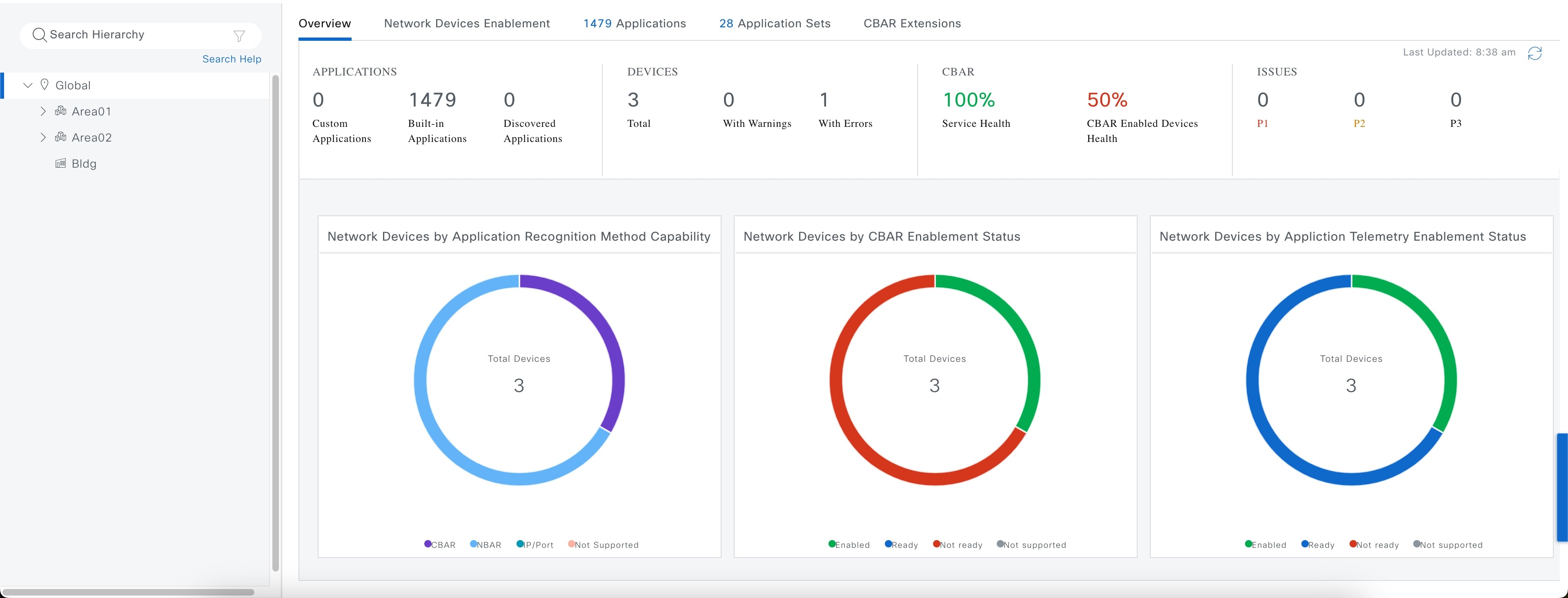
This table describes the dashlets and charts that are available in the Overview tab in Provision > Services > Application Visibility.

Item

Description

Applications

This chart displays the number of applications available in the Catalyst Center application that can be used in the Application Policy. The applications are classified accordingly:

  • Custom: Applications added by a user

  • Built-in: Preinstalled applications in Catalyst Center

  • Discovered: Applications discovered by different recognition methods and imported into the application registry

Note

 
The chart shows that the applications observed only on CBAR-enabled devices.

Devices

Shows the total number of devices, devices with warning, and devices with error.

CBAR

This widget displays the service health and the average health score for all CBAR-enabled devices. The device is healthy if there are no outstanding errors or warnings on that device.

The CBAR health score is calculated across all CBAR-enabled devices.

You can view the CBAR health of each CBAR-enabled device. A 0% CBAR health score indicates that the device has at least one error (P1). A 50% CBAR health score indicates that the device has no errors but has at least one warning (P2). A 100% CBAR health score indicates a healthy device.

Issues

All issues are classified by priority:

  • Errors (P1)

  • Warnings (P2)

  • Others (P3)

Click the P1, P2, and P3 tabs to view the device issues and remedy details.

Network Devices by Application Recognition Method

This chart displays the number of devices classified by each of the application recognition methods:

  • CBAR: CBAR-enabled devices such as routers and switches

  • NBAR: NBAR-based devices such as routers, switches, Cisco Wireless Controllers, and Cisco Catalyst 9800 Series Wireless Controller

  • IP/port: IP/port-based devices such as switches

  • Not supported: Devices that aren’t supported by any of the preceding methods

Network Devices by CBAR Enablement Status

This chart displays the device count in each CBAR readiness status.

  • Enabled: Devices that are CBAR-enabled

  • Ready: Devices that are ready for enabling CBAR

    Note


    The info icon next to Ready status shows that the respective device is wireless enabled.

  • Not Ready: Devices that support CBAR but aren’t ready for enabling CBAR due to some issues

  • Not Supported: Devices that don’t support CBAR

Network Devices by Application Telemetry Enablement Status

This chart displays the device application telemetry enablement status.

  • Enabled: Devices that are application telemetry-enabled

  • Ready: Devices that are ready for enabling application telemetry

  • Not Ready: Devices that support application telemetry but aren’t ready for enabling application telemetry due to some issues

  • Not Supported: Devices that don’t support application telemetry

This table describes the device information and statuses that are available in Site Devices table, under Network Devices Enablement tab:

Column

Description

Device Name

Name of the device. Click the device name to view the CBAR Service Status.

Management IP

IP address of the device.

Device Type

Group of related devices, such as routers, switches and hubs, or wireless controllers.

Site

The site to which the device is assigned.

Fabric

The fabric domain to which the device is assigned.

Role

Role assigned to each discovered device during the scan process. The device role is used to identify and group devices according to their responsibilities and placement within the network. If Catalyst Center cannot determine a device role, it sets the device role to Unknown.

Active Recognition Method

Shows the device recognition method (CBAR, NBAR, IP/Port, or Not Supported).

OS Version

Cisco IOS software that is currently running on the device.

CBAR Readiness Status

Hover over the status displayed in the CBAR Readiness Status column to view the Remedy message.

Protocol Pack Version

Shows the current version of the protocol pack installed on the device and the protocol pack update status.

Device Registry Status

Shows the synchronization status of the device with the application registry. Hover over the info icon or the error icon to view more details about the synchronization status.

CBAR Deployment Status

Shows the CBAR deployment status.

For more information, see Reconfigure CBAR on network devices.

Service Health Status

Click the issues in the Service Health Status column to open the CBAR Service status page, which displays a complete list of issues and the service status information of a device. If you click the Cisco Catalyst 9K device name, you can view the footprint (service load, CPU, and flows) of the CBAR service.

Application Telemetry Readiness Status

Shows the device readiness for Application Telemetry.

Application Telemetry Deployment Status

Shows Application Telemetry deployment status for the device. If the deployment fails, click the link to view the details of failure.

Application QoS Policy

The application policy applied to the device. For Cisco Wireless Controllers with more than one application policy, the number of application policies applied and the name of all the applied application policies are displayed.

WAN Interfaces

Shows the number of WAN interfaces. Click the WAN interface details to view the WAN connectivity settings for the device.

Trunk Interfaces

Shows the number of Trunk interfaces. Click the Trunk interface details to view the Trunk connectivity settings for the device.

Configure CBAR cloud

The Application Visibility service uses the CBAR cloud to enrich the protocol pack and enhance visibility for unknown applications by sending and receiving data from the cloud.

Procedure


Step 1

From the main menu, choose Provision > Application Visibility.

Step 2

Click CBAR Extensions > CBAR Cloud tab.

Step 3

Click the cloud authentication link to connect with Cisco Cloud Services, to enable CBAR and to gain access to CBAR Application Intelligence data.

You are redirected to System > Settings > Cloud Authentication window.

Step 4

You should generate a token in Cisco Cloud Services and enter it in Cloud Authentication window. Click Where did I get my token Encryption Key link to generate a token.

If you do not have a Cisco Cloud Services account, click the dna.cisco.com link.

Step 5

In the Cisco Cloud Services GUI, click the menu icon, click Applications, and choose Products.

Step 6

From the Region drop-down list, choose the appropriate region and click Register.

Step 7

In the Register Product pane, enter the required details, such as Host Name/IP, Name, and Description (if any). Choose the appropriate type of product being registered from the Type drop-down list, such as Catalyst Center. Click Register.

Note


Check the Enable Cloud Access Login check box to enable automatic login from your Cisco Cloud Services to Catalyst Center.

The OTP redemption occurs automatically, and Catalyst Center opens in a new window.

Step 8

If you want to connect manually, the OTP Generated dialog box appears after successful registration of Catalyst Center. To copy the OTP, click Copy, and click Close.

Step 9

Navigate back to the Cloud Authentication window to establish the connection:

  1. In the Catalyst Center GUI, click the menu icon and choose System > Settings > Cloud Authentication.

  2. Click Add OTP Key.

  3. In the OTP Code field, paste the OTP that you generated and copied in the Cisco Cloud Services application, and click Done.

On successful establishment of the connection, CBAR Cloud is enabled by default.

Step 10

You can view the list of available CBAR Dynamic Application Feeds under CBAR Cloud tab. To enable all the application feeds, click All radio button.

Note


The newly introduced application feed is automatically enabled for your network, if you select all feeds.

To enable the required application feeds:

  1. Click Selected only radio button.

  2. Check the check box next to the application feed that you want to select.

  3. Click Apply.

Note


In Selected only mode, the newly introduced application feeds are not imported to the network until you manually choose it.


Enable or disable CBAR cloud

Before you begin

Ensure to establish connection between Catalyst Center and Cisco Cloud Services. For more information, see Configure CBAR cloud.

Procedure


Step 1

From the main menu, choose Provision > Application Visibility.

Step 2

Click CBAR Extensions > CBAR Cloud tab.

Step 3

Do one of these tasks:

  • To enable CBAR cloud, click the Enable toggle button.

  • To disable CBAR cloud, click the Enable toggle button and click Yes in the subsequent dialog box.


Enable CBAR on network devices

Before you begin

  • The devices must be assigned to a site.

  • It is recommended to configure CBAR Cloud before enabling CBAR on the network devices. For more information, see Configure CBAR cloud.

Procedure


Step 1

From the main menu, choose Provision > Application Visibility > Network Devices Enablement tab.

The Site Devices table displays. To view all the columns, click the vertical ellipsis and then click All.

Step 2

Enable CBAR on either selected devices or all devices.

If you decide to enable CBAR on...

Then...

all devices,

  1. From the CBAR drop-down list, choose Enable CBAR on all ready devices.

  2. In the warning dialog box, click Yes.

selected devices,

  1. Check the check box next to the device name to choose the device.

  2. From the CBAR drop-down list, choose Enable CBAR on selected devices.

  3. In the warning dialog box, click Yes.

Step 3

After confirmation, on the Enable CBAR slide-in pane, review the device details and click Enable.

Step 4

Schedule the task for deployment.

Depending on Visibility and Control of Configurations settings, you can either:

Step 5

On the Tasks window, monitor the task deployment.


Disable CBAR on network devices

Procedure


Step 1

From the main menu, choose Provision > Application Visibility > Network Devices Enablement tab.

The Site Devices table displays. To view all the columns, click the vertical ellipsis and then click All.

Step 2

Disable CBAR on either selected devices or all devices.

If you decide to disable CBAR on...

Then...

all devices,

  1. From the CBAR drop-down list, choose Disable CBAR on all devices.

  2. In the warning dialog box, click Yes.

selected devices,

  1. Check the check box next to the device name to choose the device.

  2. From the CBAR drop-down list, choose Disable CBAR on selected devices.

  3. In the warning dialog box, click Yes.

Step 3

After confirmation, on the Disable CBAR slide-in pane, schedule the task for deployment.

Depending on Visibility and Control of Configurations settings, you can either:

Step 4

On the Tasks window, monitor the task deployment.


Enable Application Telemetry

Before you begin

We recommend that you configure CBAR Cloud before enabling Application Telemetry. For more information, see Configure CBAR cloud.

Procedure


Step 1

From the main menu, choose Provision > Application Visibility.

Step 2

Click the Network Devices Enablement tab.

Step 3

In the Site Devices table, do these steps to enable Application Telemetry:

  1. Choose the devices.

  2. From the Application Telemetry drop-down list, choose Enable Application Telemetry.

  3. In the Enable Application Telemetry window, do these tasks:

    • Click the Generate Configure Preview radio button and click Preview.

    • In the Enable Application Telemetry Task window, Catalyst Center displays a side-by-side comparison of the running configuration and the planned configuration for the first listed device.

    • Review the device configurations and then, when you’re ready, click Deploy.

    • Choose the Now or Later scheduling option and click Deploy.

    Note


    The Application Telemetry column shows the application telemetry deployment status.

    If the application telemetry deployment fails for a device, click the link under Application Telemetry Deployment Status column to view the failure reason.


Disable Application Telemetry

Procedure


Step 1

From the main menu, choose Provision > Application Visibility.

Step 2

Click the Network Devices Enablement tab.

Step 3

To disable Application Telemetry, do these steps:

  1. Choose the devices in the Site Devices table.

  2. From the Application Telemetry drop-down list, choose Disable Application Telemetry and click Yes in the subsequent warning dialog box.


Update the protocol pack on a CBAR-enabled device

You can upgrade the protocol pack on any device that supports CBAR to the latest or any specific protocol pack. You can update protocol pack manually or enable automatic protocol pack update.


Note


  • Automatic Protocol Pack update menu is disabled when CBAR cloud connector is disabled.

  • Manual Protocol Pack update menu is disabled when Automatic Protocol Pack is enabled.


Before you begin

  • Configure Cisco credentials on System Settings. For more information about configuring Cisco credentials, see the Cisco Catalyst Center Administration Guide.

  • Devices must support CBAR.

  • CBAR must be enabled on the device.

  • Protocol packs for the device must be available on cisco.com.

Procedure


Step 1

From the main menu, choose Provision > Services > Application Visibility.

Step 2

Click the Network Devices Enablement tab.

Step 3

In Site Devices table, check the status shown in the Protocol Pack Version column.

You can click the Outdated status to view the list of applicable protocols packs in the Update Protocol Pack window.

Step 4

Click Update corresponding to the required protocol pack version in the Update Protocol Pack window.

The Protocol Pack Version column shows In progress status. Click the info icon to view the current updating version. If the Protocol Pack Version column shows Update failed status, click the error icon to view the failure reason.

Step 5

If you want to manually update all the devices or selected devices to the latest protocol pack, do these tasks:

To update the protocol pack on all applicable CBAR-enabled devices:

  • From the Update Protocol Pack drop-down list, choose Update All Devices and click Yes in the subsequent warning dialog box.

To update the protocol pack on the selected devices:

  • Choose the devices in the Site Devices table.

  • From the Update Protocol Pack drop-down list, choose Update Selected Devices and click Yes in the subsequent warning dialog box.

To update the protocol pack on the selected devices from the file:

  • Choose the devices in the Site Devices table.

  • From the Update Protocol Pack drop-down list, choose Update Selected Devices From File.

  • In the Update Protocol Pack From File slide-in pane you can either drag and drop the file into the drag-and-drop area or click Choose a file, browse to the location of the file, and click Open.

  • Click Import.

Step 6

If you want to automatically update protocol pack for all the devices, do these tasks:

  • From the Update Protocol Pack drop-down list, enable Auto Update toggle button and click Yes in the subsequent warning dialog box.

Note


By default, all ready devices are included for Auto Update.

To exclude selected devices from automatic protocol pack update:

  • Choose the devices in the Site Devices table.

  • From the Update Protocol Pack drop-down list, choose Exclude Selected Devices and click Yes in the subsequent warning dialog box.

To include selected devices for automatic protocol pack update:

  • Choose the devices in the Site Devices table.

  • From the Update Protocol Pack drop-down list, choose Include Selected Devices and click Yes in the subsequent warning dialog box.


Reconfigure CBAR on network devices

You can include or exclude interfaces from Site Devices table in the Application Visibility > Network Devices Enablement window.

Procedure


Step 1

From the main menu, choose Provision > Services > Application Visibility.

Step 2

Click the Network Devices Enablement tab.

Step 3

In the Site Devices table, click Re-Configure in the CBAR Deployment status column for the device that you want to configure and do these steps:

  1. In the Enable CBAR slide-in pane, search for the device name or locate the device and click View Interfaces.

  2. Locate the interface that you want to exclude.

  3. In the Status column, click the toggle button to disable the interface and click Save.

Step 4

To include interfaces, choose Excluded Interfaces and enable the toggle button next to the desired interfaces, and click Save.

Step 5

Click Enable.

Step 6

Schedule the task for deployment.

Depending on Visibility and Control of Configurations settings, you can either:

Step 7

On the Tasks window, monitor the task deployment.


Applications and application sets

Applications are the software programs or network signaling protocols that are used in your network. Catalyst Center supports all of the applications in the Cisco Next Generation Network-Based Application Recognition (NBAR2) library of approximately 1400 distinct applications.

Applications are grouped into logical groups called application sets. An application set can be assigned a business relevance within a policy.

Applications are mapped into industry standard-based traffic classes, as defined in RFC 4594, that have similar traffic treatment requirements. The traffic classes define the treatments (such as Differentiated Services Code Point [DSCP] marking, queuing, and dropping) that will be applied to the application traffic, based on the business relevance group that is assigned.

If you have additional applications that are not included in Catalyst Center, you can add them as custom applications and assign them to application sets.

Unidirectional and bidirectional application traffic

Some applications are completely symmetrical and require identical bandwidth provisioning on both ends of the connection. Traffic for such applications is described as bidirectional. For example, if 100 kbps of Low-Latency Queueing (LLQ) is assigned to voice traffic in one direction, 100 kbps of LLQ must also be provisioned for voice traffic in the opposite direction. This scenario assumes that the same Voice over IP (VoIP) coder-decoders (codecs) are being used in both directions and do not account for multicast Music-on-Hold (MoH) provisioning. However, certain applications, such as streaming video and multicast MoH, are most often unidirectional. Therefore, it might be unnecessary, and even inefficient, to provision any bandwidth guarantees for such traffic on a branch router for the branch-to-campus direction of traffic flow.

Catalyst Center lets you specify whether an application is unidirectional or bidirectional for a particular policy.

On switches and wireless controllers, NBAR2 and custom applications are unidirectional by default. However, on routers, NBAR2 applications are bidirectional by default.

Custom applications

Custom applications are applications that you add to Catalyst Center. You can view the number of custom applications available in the Overview window. For wired devices, you can define applications based on server name, IP address and port, or URL. You can define custom applications for Cisco Catalyst 9800 Series Wireless Controllers and not for Cisco AireOS controllers.

When you define an application according to its IP address and port, you can also define a DSCP value and port classification.

To simplify the configuration process, you can define an application based on another application that has similar traffic and service-level requirements. Catalyst Center copies the other application's traffic class settings to the application that you are defining.

Catalyst Center does not configure ACLs for port numbers 80, 443, 53, 5353, and 8080, even if they are defined as part of a custom application. If the custom application has a transport IP defined, Catalyst Center configures the application on the devices.


Note


For a custom application to be programmed on devices when a policy is deployed, you must assign the custom application to one of the application sets defined in the policy.


Discovered applications

Discovered applications are applications that are discovered by importing from the recommended customization, such as an Infoblox DNS server, or by importing from the recommended unclassified applications flow.

The unclassified traffic can come from any flow that the CBAR-enabled device identifies, but that is not recognized by the NBAR engine. In such cases, the applications that have a meaningful bit rate are reported as unclassified and can be imported and used as applications in Catalyst Center.

The Application Visibility service lets Catalyst Center connect with external authoritative sources through the CBAR cloud to help classify the unclassified traffic or help generate improved signatures.

The available external authoritative sources are Google Meet, Service Now, Sugarcrm, Telegram, SAP, Microsoft Office 365 Cloud Connector, Box, RingCentral, Github, Crashplan, Intuit, Workday, Zscaler, Atlassian, Amazon Chime, Zoom, Dropbox, Webex, Whatsapp, Cisco Meraki, and Salesforce. This list is dynamic. As new sources are added to the cloud, the list is updated. To view the list, choose Application Visibility > CBAR Extensions > CBAR Cloud.


Note


You must configure a CBAR cloud connector before configuring the applications.


The discovered applications are imported to the application registry.

Favorite applications

Catalyst Center lets you flag applications that you want to configure on devices before all other applications. Flagging an application as a favorite helps to ensure that the QoS policies for your favorite applications get configured on devices. For more information, see Processing order for devices with limited resources.

When custom applications are created they are marked as favorite applications.

Although there is no limit to the number of applications that you can mark as favorites, designating only a small number of favorite applications (for example, fewer than 25) helps to ensure that these applications are treated correctly from a business-relevance perspective in deployments with network devices that have limited ternary content addressable memory (TCAM).

Favorite applications can belong to any business-relevance group or traffic class and are configured system-wide, not on a per-policy basis. For example, if you flag the Cisco Jabber video application as a favorite, the application is flagged as a favorite in all policies.

Keep in mind that not only can business-relevant applications be flagged as favorites, even business-irrelevant applications can be flagged as such. For example, if administrators notice a lot of unwanted Netflix traffic on the network, they might chose to flag Netflix as a favorite application (despite it being assigned as business-irrelevant). In this case, Netflix is programmed into the device policies before other business-irrelevant applications, ensuring that the business intent of controlling this application is realized.

Configure applications and application sets

These subsections describe the various tasks that you can perform in the context of applications and application sets.


Note


You can edit or delete only custom and discovered applications. You can edit or delete a maximum of 100 custom and discovered applications at one instance. If you choose applications for editing or deleting, a notification message indicates the number of applications that can be edited or deleted, excluding the number of chosen applications.


Change application settings

You can change the application set or traffic class of an existing CBAR, custom, or discovered application.
Procedure

Step 1

From the main menu, choose Provision > Services > Application Visibility.

Step 2

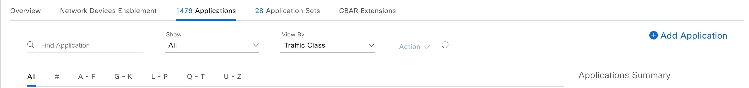
Click Applications tab.

Step 3

Use the Search, Show, or View By fields to locate the application that you want to change.

You can search applications based on their name, port number, and traffic class.

Step 4

Click the application name.

Step 5

In the dialog box, change one or both settings:

  • Traffic Class: Choose a traffic class from the drop-down list. Valid traffic classes are BROADCAST_VIDEO, BULK_DATA, MULTIMEDIA_CONFERENCING, MULTIMEDIA_STREAMING, NETWORK_CONTROL, OPS_ADMIN_MGMT, REAL_TIME_INTERACTIVE, SIGNALING, TRANSACTIONAL_DATA, VOIP_TELEPHONY.

  • Application Set: Choose an application set from the drop-down list. Valid application sets are authentication-services, backup-and-storage, collaboration-apps, consumer-browsing, consumer-file-sharing, consumer-gaming, consumer-media, consumer-misc, consumer-social-networking, database-apps, desktop-virtualization, email, enterprise-ipc, file-sharing, generic-browsing, generic-media, generic-misc, tunneling, local-services, naming-services, network-control, network-management, remote-access, saas-apps, signaling, software-development-tools, software-updates, streaming-media.

Step 6

Click Save.


Create a server name-based custom application

If you have applications that are not in Catalyst Center, you can add them as custom applications.

Procedure

Step 1

From the main menu, choose Provision > Services > Application Visibility.

Step 2

Click the Application tab.

Step 3

Click Add Application at the top-right corner of the window.

Step 4

In the slide-in pane, provide the necessary information in these fields:

  • Application name: Name of the custom application. The name can contain up to 24 alphanumeric characters, including underscores and hyphens. The underscore and hyphen are the only special characters allowed in the application name.

  • Type: Method by which users access the application. Choose Server Name for applications that are accessible through a server.

  • Server name: Name of the server that hosts the application.

  • Similar to: Application with similar traffic-handling requirements. Click the radio button to select this option, and then select an application from the drop-down list. Catalyst Center copies the other application's traffic class to the application that you are defining.

  • Traffic class: Traffic class to which the application belongs. Valid values are BULK_DATA, TRANSACTIONAL_DATA, OPS_ADMIN_MGMT, NETWORK_CONTROL, VOIP_TELEPHONY, MULTIMEDIA_CONFERENCING, MULTIMEDIA_STREAMING, BROADCAST_VIDEO, REAL_TIME_INTERACTIVE, and SIGNALING.

  • Application set: Application set is where you want the application to reside. Valid application sets are authentication-services, backup-and-storage, collaboration-apps, consumer-browsing, consumer-file-sharing, consumer-gaming, consumer-media, consumer-misc, consumer-social-networking, custom applications, database-apps, desktop-virtualization, email, enterprise-ipc, file-sharing, generic-browsing, generic-media, generic-misc, tunneling, local-services, naming-services, network-control, network-management, remote-access, saas-apps, signaling, software-development-tools, software-updates, streaming-media.

Step 5

Click Save.


Create an IP address and port-based custom application

If you have applications that are not in Catalyst Center, you can add them as custom applications.

Procedure

Step 1

From the main menu, choose Provision > Services > Application Visibility.

Step 2

Click the Application tab.

Step 3

Click Add Application.

Step 4

In the Application name field, enter a name for the custom application. The name can contain up to 24 alphanumeric characters, including underscores and hyphens. The underscore and hyphen are the only special characters allowed in the application name.

Step 5

In the Type area, click the Server IP/Port radio button to indicate that the application is accessible through an IP address and port.

Step 6

Check the DSCP check box and define a DSCP value. If you do not define a value, the default value is Best Effort. Best-effort service is essentially the default behavior of the network device without any QoS.

Step 7

Check the IP/Port Classifiers check box to define the IP address and subnet, protocol, and port or port range for an application. Valid protocols are IP, TCP, UDP, and TCP/UDP. If you select the IP protocol, you do not define a port number or range. Click to add more classifiers.

Step 8

Define your application traffic-handling requirements using one of these methods:

  • Similar To: If your application has similar traffic-handling requirements as an existing application, click the Similar To radio-button and choose the application from the drop-down list. Catalyst Center copies the traffic class of the other application to the application that you are defining.
  • Traffic Class: If you know the traffic class that you want to define for your application, click the Traffic Class radio button and choose the traffic class from the drop-down list. Valid values are BULK_DATA, TRANSACTIONAL_DATA, OPS_ADMIN_MGMT, NETWORK_CONTROL, VOIP_TELEPHONY, MULTIMEDIA_CONFERENCING, MULTIMEDIA_STREAMING, BROADCAST_VIDEO, REAL_TIME_INTERACTIVE, and SIGNALING.

Step 9

From the Application Set drop-down list, choose the application set to which the application will belong. Valid application sets are authentication-services, backup-and-storage, collaboration-apps, consumer-browsing, consumer-file-sharing, consumer-gaming, consumer-media, consumer-misc, consumer-social-networking, custom applications, database-apps, desktop-virtualization, email, enterprise-ipc, file-sharing, generic-browsing, generic-media, generic-misc, tunneling, local-services, naming-services, network-control, network-management, remote-access, saas-apps, signaling, software-development-tools, software-updates, streaming-media.

Step 10

Click Save.


Create a URL-based custom application

If you have applications that are not in Catalyst Center, you can add them as custom applications.

Procedure

Step 1

From the main menu, choose Provision > Services > Application Visibility.

Step 2

Click the Application tab.

Step 3

Click Add Application.

The Add Application dialog box appears.

Step 4

In the Application name field, enter the name of the custom application. The name can contain up to 24 alphanumeric characters, including underscores and hyphens. (Underscores and hyphens are the only special characters allowed in the application name.)

Step 5

For Type, click the URL radio button.

Step 6

In the URL field, enter the URL used to reach the application.

Step 7

Configure the traffic class:

  • To use the same traffic class as another application with similar traffic-handling requirements, click the Similar To radio button and choose an application from the drop-down list.
  • To specify the traffic class, click the Traffic Class radio button and choose a traffic class from the drop-down list. Valid values are BULK_DATA, TRANSACTIONAL_DATA, OPS_ADMIN_MGMT, NETWORK_CONTROL, VOIP_TELEPHONY, MULTIMEDIA_CONFERENCING, MULTIMEDIA_STREAMING, BROADCAST_VIDEO, REAL_TIME_INTERACTIVE, and SIGNALING.

Step 8

From the Application Set drop-down list, choose an application set in which you want the application to reside.

Step 9

Click Save.


Edit or delete a custom application

If required, you can change or delete a custom application.


Note


You cannot delete a custom application that is directly referenced by an application policy. Application policies typically reference application sets and not individual applications. However, if a policy has special definitions for an application (such as a consumer or producer assignment or bidirectional bandwidth provisioning), the policy has a direct reference to the application. As such, you must remove the special definitions or remove the reference to the application entirely before you can delete the application.


Procedure

Step 1

From the main menu, choose Provision > Services > Application Visibility.

Step 2

Click the Application tab.

Step 3

Use the Search, Show, or View By fields to locate the application that you want to change.

You can search applications based on their name, port number, and traffic class.

Step 4

To edit the application:

  1. Click the application name and make the required changes. For information about the fields, see Create a server name-based custom application, Create an IP address and port-based custom application, or Create a URL-based custom application.

  2. Click Save.

Alternatively, choose the application and from the Actions drop-down list, click Edit to edit an application.

Note

 
When policy is redeployed, the edited custom applications are not reconfigured on Cisco Catalyst 9800 Series Wireless Controller.

Step 5

To delete the application, click in the application box, and then click OK to confirm.

Alternatively, you can do these steps to delete the application:

  1. Check the check box next to an application name. You can also choose multiple applications.

  2. From the Actions drop-down list, click Delete option.

  3. Click OK to confirm.


Mark an application as favorite

You can mark an application as a favorite to designate that the application's QoS configuration must be deployed to devices before other applications' QoS configuration. An application marked as favorite has a yellow star next to it.

When you add or edit a policy, applications marked as a favorites are listed at the top of the application set.

Applications are configured system-wide, not on a per-policy basis. For more information, see Favorite applications.

Procedure

Step 1

From the main menu, choose Provision > Services > Application Visibility.

Step 2

Click the Application tab.

Step 3

Locate the application that you want to mark as a favorite.

Step 4

Click the star icon.


Create a custom application set

If none of the application sets fits your needs, you can create a custom application set.

Procedure

Step 1

From the main menu, choose Provision > Services > Application Visibility.

Step 2

Click the Application Sets tab.

Step 3

Click Add Application Set.

Step 4

In the slide-in pane, enter a name for the new application set.

Catalyst Center creates the new application set; however, it contains no applications.

Step 5

Choose a Default Business Relevance from the drop-down list. Default Business Relevance is the business relevance level in the absence of a concreate application QoS, this level will appear in Assurance for sites that are not assigned to a policy.

Step 6

Click Save.

Step 7

Use the Search, Show, or View By fields to locate the application set.

You can search applications based on their name, port number, and traffic class.

Step 8

Locate the applications that you want to move into the new application set.

Step 9

Check the check box next to the applications that you want to move.

Step 10

Drag and drop the applications into the new application set.


Edit or delete a custom application set

If required, you can change or delete a custom application set.


Note


You cannot delete a custom application set that is referenced by an application policy. You must remove the application set from the policy before you delete the application set.


Procedure

Step 1

From the main menu, choose Provision > Services > Application Visibility.

Step 2

Click the Application Sets tab.

Step 3

Use the Search, Show, or View By fields to locate the application set that you want to change.

You can search applications based on their name, port number, and traffic class.

Step 4

Do one of these tasks:

  • To edit the application set, drag and drop applications into or out of the application set. Click OK to confirm each change.
  • To delete the application set, click in the application set box, and then click OK to confirm.

Discover unclassified applications

The Application Visibility service in Catalyst Center obtains information on classified and unclassified domains and sockets from devices and displays that information in the Observed Traffic chart. The number of unclassified server names and IP/ports that are discovered by the Application Visibility service is shown under Recommendations.

You can add the unclassified server names and IP/ports to the Application Registry.


Note


You can add a maximum of 1100 discovered applications in the Application Registry.


Procedure


Step 1

From the main menu, choose Provision > Services > Application Visibility.

Step 2

Click the CBAR Extensions > Discovered Applications tab.

Step 3

The table lists the discovered servers or IP/ports that are not classified. Choose the server and check the Hide Ignored Applications check box if you want to hide the selected server or IP/ports in the table.

Step 4

Choose the server or IP/ports that you want to import as an application in the Application Registry.

Step 5

Choose the required Application, Application Set, and Traffic Class from the drop-down list.

Step 6

Click Import.

Step 7

Click the Applications tab and from Show drop-down list choose Discovered to view the imported application.


Application Visibility service support for the Catalyst Center Traffic Telemetry Appliance

The Catalyst Center Traffic Telemetry Appliance generates endpoint telemetry from mirrored IP network traffic and shares the telemetry data with Catalyst Center for endpoint visibility and segmentation.

The prerequisites for enabling CBAR on the Catalyst Center Traffic Telemetry Appliance include:

  • The device must be assigned to a site.

  • The device role must be set to Distribution mode.

You can configure custom applications with attribute sets and maps on the Catalyst Center Traffic Telemetry Appliance without configuring a QoS policy. For more information, see Create an application policy and Deploy an application policy.

Discover Infoblox applications

You can integrate Catalyst Center with an organizational Infoblox DNS server to resolve unclassified traffic based on server names.

Before you begin

  • The Infoblox WAPI version must be 1.5 or later. To check the Infoblox WAPI version, log in to the Infoblox server and choose Help > Documentation > WAPI Documentation.

  • Create a role with at least Read Only permissions and assign the role to the Infoblox user. For more information, see Manage Users in the Cisco Catalyst Center Administrator Guide.

Procedure


Step 1

From the main menu, choose Provision > Services > Application Visibility.

Step 2

Click the CBAR Extensions > Infoblox tab.

Step 3

Under Infoblox, click the Here link to configure IPAM/DNS server credentials in Catalyst Center.

Step 4

Complete the IPAM settings. For more information, see Configure an IP Address Manager in the Cisco Catalyst Center Administrator Guide.

Step 5

Go back to Infoblox and click the icon to complete these settings:

  • Check the All DNS Zones check box, or choose the required DNS zones from the DNS Zones to Inspect drop-down list. The drop-down list shows the DNS zones defined in the Infoblox server.

  • From the Inspect drop-down list, choose the required inspection record.

  • Check the Read Application name from check box and click the Extensible Attribute or AVC RRTYPE format radio button. If you click the Extensible Attribute radio button, enter the extensible attribute name that contains descriptive application names.

  • From Default Traffic Class, choose the default traffic class for classifying the Infoblox applications.

  • From Default Application Set, choose the default application set for classifying the Infoblox applications.

Step 6

Click Save.

Step 7

Choose the application that you want to import and complete these tasks:

  • If the application does not have a name defined in the Infoblox server, edit the application name.

  • Choose the required application set and traffic class from the drop-down list if you want to change the default application set and traffic class defined in the Infoblox.

Step 8

Click Import.

Step 9

Click the Applications tab and choose Discovered in the Show drop-down list to view or edit the imported Infoblox applications.

If you change the server name of an application after importing the application, the Application Status column in the Infoblox window shows the status of the application as Updated. The application name that you see in the Application Status column is the new server name of the application. Click the info icon to view the old server names of the application.


Edit or delete a discovered application

If required, you can edit or delete a discovered application.

Procedure


Step 1

From the main menu, choose Provision > Services > Application Visibility.

Step 2

Click the Applications tab.

Step 3

Use the Search, Show, or View By fields to locate the discovered application that you want to change.

You can search for applications based on their name, port number, and traffic class.

Step 4

Do one of these tasks:

  • To edit the application:
    1. Click the application name and make the required changes.

      For discovered applications, you can edit only the Attribute Set and Traffic Class.

    2. Click Save.

  • To delete the application:
    1. Select the application and choose Delete option from the Action drop-down list at the top of the window.

    2. Click OK in the subsequent warning dialog box that appears on the window.


Application hosting

These sections provide information about application hosting.

About application hosting

Application hosting lets you manage the lifecycle of third-party applications on devices managed by Catalyst Center.

You can host third-party docker applications on:

  • Cisco Catalyst 9300 Series switches running Cisco IOS-XE software version 16.12.1s or later.

  • Cisco Catalyst 9100 Series Access Points running Cisco IOS-XE software version 17.3.1 or later.

  • Cisco Catalyst 9400 Series switches running Cisco IOS-XE software version 17.1 or later.

  • Cisco Catalyst IE3200, IE3300 (4 GB), IE3400, and IE3400H Series switches running Cisco IOS-XE software version 17.3 or later.

  • Cisco Catalyst IE3100 and IE 3105 Rugged Series switches running Cisco IOS-XE software version 17.15 or later.

  • Cisco Catalyst IE9300 Series switches running Cisco IOS-XE software version 17.9 or later.


Note


The disk space allocated in Catalyst Center for the hosted applications is limited to 5 GB.


Install or update the application hosting service package

Before you begin

Only a user with SUPER-ADMIN-ROLE permissions can perform this procedure.

Procedure


Step 1

From the main menu, choose System > Software Management. Alternatively, click the cloud icon and click the Go to Software Management link.

Step 2

Under Available Application for the release, choose Application Hosting package and click Install.


Prerequisites for application hosting

To enable application hosting on a Cisco Catalyst 9000 device, these prerequisites must be fulfilled:

  • Configure NETCONF port on the device before discovery.

  • Configure a secure HTTP server on the switch where the applications will be hosted.

  • Configure local or AAA authentication server for HTTPS user authentication on the switch. You must configure the username and password with privilege level 15.

  • Ensure Cisco Catalyst 9300 Series switches are running Cisco IOS XE 16.12.x or later version and Cisco Catalyst 9400 Series switches are running Cisco IOS XE 17.1.x or later version.

  • Ensure that the device has an external USB SSD pluggable storage (only for the switches of 9300 family).

  • Verify that the configuration on the switch is correct. Open the WebUI on the switch and log in as the HTTPS user that is configured on Catalyst Center.

    This example shows a working configuration on a switch:

    prompt# sh run | sec ip http
    ip http server
    ip http authentication local
    ip http secure-server
    ip http max-connections 16
    ip http client source-interface GigabitEthernet0/0
    
    Additional configuration for switches with a Cisco IOS XE release that is earlier than 17.3:
    ip http secure-active-session-modules dnac
    ip http session-module-list dnac NG_WEBUI
    ip http active-session-modules none
  • On Catalyst Center, configure the HTTPS credentials while manually adding the device. The HTTPS username, password, and port number are mandatory for application hosting. The default port number is 443. You can also edit the device credentials; see Update network device credentials. If you edit a device that is already managed, resynchronize that device in the inventory before it is used for application hosting-related actions.


Note


Application hosting HA is not supported on three-node Catalyst Center clusters.


View device readiness to host an application

You must check the readiness of the Cisco Catalyst 9300 Series switch to host the application before you can install an application on the switch.

Procedure


Step 1

From the main menu, choose Provision > Services > Application Hosting.

Step 2

Click All Devices.

Step 3

View the list of devices that are capable of hosting applications. The App Hosting Status indicates the readiness of the device to host an application. Click See Details to view the list of readiness checks performed on the device.


Add an application

You can add a Cisco package or a docker application.

Before you begin

  • Cisco Package: You must package the application using IOS SDK tools so that the application is compatible with IOS XE operating systems.

  • Docker: You must save the docker image as a tar file. Enter these command to store the docker image as a tar file:

    docker save -o <path for generated tar file> <image name:tag>
    Example: docker save -o alpine-tcpdump.tar itsthenetwork/alpine-tcpdump:latest

Procedure


Step 1

From the main menu, choose Provision > Services > Application Hosting.

Step 2

Click New Application.

Step 3

Choose the application and category from the drop-down list.

Step 4

Click Select and choose the application to upload.

Step 5

Click Upload.

You can view the newly added application in the App Hosting page.

Automatic download of the ThousandEyes Enterprise Agent application

The ThousandEyes Enterprise Agent application lets you monitor your network and oversee the network traffic paths across internal, external, carrier, and internet networks in real time. The advantage of the ThousandEyes Enterprise Agent application is that you do not have to import this application manually in your Catalyst Center Application Hosting Service.

When these conditions are met, the ThousandEyes Enterprise Agent application is downloaded automatically within 10 minutes of starting the Application Hosting Service:

  • At least one managed device is present in the inventory, without any manageability errors.

  • An inventory resync has succeeded at least once on the managed device.

To manually download the application, click this link to the ThousandEyes Enterprise Agent .tar file:

thousandeyes-enterprise-agent.cat9k.tar

If there is no internet connection, you can set a proxy connection from the console using this command:

magctl service setenv app-hosting http_proxy <proxy-value>

Set the proxy value to connect to the ThousandEyes Enterprise Agent application.

Update an application

You can update the application added in Catalyst Center.

Procedure


Step 1

From the main menu, choose Provision > Services > Application Hosting.

You can view the available applications in the App Hosting window.

Step 2

Choose the application that you want to update.

Step 3

Click Update App.

Step 4

Choose a new version of the application to be uploaded.

Step 5

Click Upload.


Start an application

You can start an application in Catalyst Center.

Procedure


Step 1

From the main menu, choose Provision > Services > Application Hosting.

Step 2

Choose the application and click Manage to view the devices that use the application.

Step 3

Choose the device that has the application that you want to start.

Step 4

From the Actions drop-down list, choose Start App.


Stop an application

You can stop an application in Catalyst Center.

Procedure


Step 1

From the main menu, choose Provision > Services > Application Hosting.

Step 2

Choose the application and click Manage to view the devices that use the application.

Step 3

Choose the device that has the application that you want to stop.

Step 4

From the Actions drop-down list, choose Stop App.


View applications hosted on a device

Before you begin

Complete the prerequisites in Prerequisites for Application Hosting.

Procedure


Step 1

From the main menu, choose Provision > Services > Application Hosting.

Step 2

To view all devices, click All Devices at the top-right corner, or to view only the devices that use a particular application, choose the application and click Manage.

If you chose to view all devices, the All Devices window shows information about the devices that are capable of hosting applications, including: Hostname, IP Address, Image Version, App Hosting Status, and Last Updated.

If you chose to view a list of devices for a particular application, the Devices window shows the information about the devices that are capable of hosting applications, including: Hostname, Device IP, App Version, App Status, Last Heard, Platform Version, and Action Status.

Step 3

In the Devices window, click Summary to view a summary of failed, stopped, and running applications on a device.

Step 4

To take an action on an application, click the Action drop-down list and choose Start, Stop, Edit, Upgrade, or Uninstall.

Step 5

Click the device link in which you want to view the installed hosting applications.

The Applications window shows the Name, Version, App Status, Monitor App, Health, and Details of the installed applications.

Note

 
Monitor App contains a link to the Application Monitoring dashboard. This link is provided in the Catalyst Center application package controller .yaml file. If the file does not contain the application dashboard URL, the Monitor App column isn't applicable.

Step 6

In the Details column, click View to get more information about an application status on the device.

Step 7

To download the log for a particular application, select the application and click Application Logs.

Step 8

To download tech support logs from the device, click Tech Support Logs.


Install an application using Application Hosting

Catalyst Center allows you to install an application on switches. For more information on the supported switches, see About application hosting.

Before you begin

Procedure


Step 1

From the main menu, choose Provision > Services > Application Hosting.

Step 2

Choose the application and click Install.

Step 3

In the Get Started window, enter a unique name for your workflow in the Task Name field and click Next.

Step 4

In the Select Site window, choose the site where you want to enable the application, and click Next.

Step 5

In the Select Switches window, choose the devices on which you want to install the application and click Next.

You can choose the devices that are in Ready and Partially Ready status. Click See Details to view the list of readiness checks performed on the device.

For devices that are in Partially Ready status, click the Check Now link in the Readiness Check window to validate the HTTPS credentials.

If you don't find your device in the Devices Table, click Import to add devices from a CSV file.

Step 6

In the Configuration App window, complete these settings:

  • Network Settings:

    • From the Select Network drop-down list, choose a VLAN to configure the application.

    • From the Address Type drop-down list, choose Static or Dynamic. If you choose Static, click the thumbnail icon and enter the IP Address, Gateway, Prefix/Mask, and DNS for the application.

  • App Resources: Check the Allocate all resources available on a device or the Customize resource allocation check box. You can check the Customize resource allocation check box and modify the maximum CPU, Memory, and Persistent Storage values to a lower value.

  • Custom Settings: Applicable only for Cisco package applications. Enter the configuration details for the attributes that are specified by the application.

  • App Data: Browse and upload the application-specific files. For information about how to identify the required application-specific files, see the relevant application document.

  • Docker Runtime Options: Enter the docker runtime options required by the application.

Step 7

In the Summary window, review the application configuration settings.

Step 8

(Optional) Click Configuration Preview to view the configuration template used to push the configuration settings on the selected devices.

Step 9

Click Provision.

Step 10

In the confirmation window, click Yes to complete the application installation on the selected devices.

Note


The installation of the application also modifies the Cisco IOS-XE configuration on the device. This change in the running configuration must be copied to the startup configuration to ensure applications function as expected after a router reload. After the application installation is complete, use the CLI Templates to copy the running configuration to the startup configuration.


Uninstall an application from a Cisco Catalyst 9300 device

You can uninstall an application from a Cisco Catalyst 9300 Series switch.

Procedure


Step 1

From the main menu, choose Provision > Services > Application Hosting.

Step 2

Choose the application and click Manage to view the devices that use the application.

Step 3

Choose the devices that have the application that you want to uninstall.

Step 4

From the Actions drop-down list, choose Uninstall App.


Edit an application configuration in a Cisco Catalyst 9300 device

You can edit an application configuration if the application requires a configuration to be up and running in a Cisco Catalyst 9300 Series switch.

Procedure


Step 1

From the main menu, choose Provision > Services > Application Hosting.

Step 2

Choose the application and click Manage to view the devices that use the application.

Step 3

Choose the device that has the application that you want to edit.

Step 4

From the Actions drop-down list, choose Edit App Config.


Delete an application

You can delete an application from Catalyst Center.

Before you begin

You must uninstall the application from all devices that are using it. For more information, see Uninstall an application from a Cisco Catalyst 9300 device.

Procedure


Step 1

From the main menu, choose Provision > Services > Application Hosting.

You can view the available hosted applications in the App Hosting window.

Step 2

Choose the application that you want to delete.

Step 3

Click Delete Application.

Step 4

In the confirmation dialog box, click OK.

The application is deleted only if it is not used by any of the devices managed by Catalyst Center.

Otherwise, an error message shows the number of devices that are using the application. Click Cancel in the confirmation dialog box and uninstall the application. For more information, see Uninstall an application from a Cisco Catalyst 9300 device.


Download application logs

You can download application logs from Catalyst Center.

Procedure


Step 1

From the main menu, choose Provision > Services > IoT Services.

Step 2

Click All Devices.

You can view the list of devices that are capable of hosting applications.

Step 3

Click App logs to download the application logs from Catalyst Center.

Step 4

In the App Logs pop-up window, choose the application logs file that you want to download and click Download.


Download device tech support logs

You can download the device tech support logs from Catalyst Center for troubleshooting purposes.

Procedure


Step 1

From the main menu, choose Provision > Services > IoT Services.

Step 2

Click All Devices.

A list of devices that are capable of hosting applications displays.

Step 3

Click Tech Support logs to download the device tech support logs.


Application hosting on Cisco Catalyst 9100 Series Access Points

These sections provide information about application hosting on Cisco Catalyst 9100 Series Access Points.

About application hosting on Cisco Catalyst 9100 Series Access Points

The move to virtual environments has prompted the need to build applications that are reusable, portable, and scalable. Application hosting gives administrators a platform for leveraging their own tools and utilities. An application, hosted on a network device, can serve a variety of purposes. This ranges from automation, configuration management monitoring, and integration with existing tool chains.

Application hosting lets you manage the lifecycle of third-party applications on devices managed by Catalyst Center. This release lets you bring in the third-party SES-imagotag IoT Connector application on Cisco Catalyst 9100 Series Access Points with Cisco IOS-XE software version 17.3 or later.

The SES-imagotag IoT Connector on Cisco Catalyst 9100 Series Access Points can handle all Electronic Shelf Label (ESL) communication.

Application hosting workflow to install and manage USB applications on Cisco Catalyst 9100 Series Access Points

Before you begin

To enable application hosting on a device, these prerequisites must be completed:

  • Enable NETCONF and set the port to 830 to discover Cisco Catalyst 9100 Series Access Points.

  • Make sure that the Cisco Catalyst 9100 Series Access Points have direct IP reachability to Catalyst Center.

  • Make sure that the Cisco Catalyst 9800 Series Wireless Controller is running Cisco IOS XE 17.3.x or later software.

  • Make sure that the Catalyst Center appliance is running the latest Catalyst Center ISO.

  • Make sure that the USB dongle is inserted in the AP. This is required for the SES-imagotag Connector application to run.

Procedure


Step 1

Check the readiness of the Cisco Catalyst 9800 Series Wireless Controller and Cisco Catalyst 9100 Series Access Points to host the application before you install it.

For more information, see View device readiness to host an application.

Step 2

Install the Application Hosting service on Catalyst Center.

For more information, see Install or update the application hosting service package.

Step 3

Add the Cisco Catalyst 9800 Series Wireless Controller to Catalyst Center.

For more information, see Add a network device.

Note


Make sure that you enable NETCONF and set the port to 830.

You must wait for the Cisco Catalyst 9800 Series Wireless Controller to move to a Managed state.

Step 4

Assign APs to a floor on the Network Hierarchy window.

For more information, see Work with APs on a floor map.

Step 5

Upload the USB application (the SES-imagotag Connector) to Catalyst Center.

For more information, see Add an application.

Step 6

Enable the IoT services.

For more information, see Enable IoT services on Cisco Catalyst 9100 Series Access Points.

Step 7

Configure the container as described in the Application Hosting on Catalyst APs Deployment Guide.


View installed hosting applications on Cisco Catalyst 9100 Series Access Points

Before you begin

Make sure the prerequisites have been met. For more information, see Prerequisites for Application Hosting.

Procedure


Step 1

From the main menu, choose Provision > Services > IoT Services.

Step 2

To view all devices, click All Devices at the top-right corner, or to view only the devices that use a particular application, choose the application and click Manage.

If you chose to view all devices, the All Devices page displays the information about the devices that are capable of hosting applications, including: Hostname, IP Address, Image Version, App Hosting Status, and Last Updated.

Note


When the App Hosting Status of an AP is Ready, to configure the updates on the AP, check the check box next to the required hostname and click Resync.

If you chose to view a list of devices for a particular application, the Devices window shows information about the devices that are capable of hosting applications, including: Hostname, Device IP, App Version, App Status, Last Heard, Platform Version, and Action Status.

Step 3

In the Devices window, click Summary to view the summary of failed, stopped, and running applications on a device.

Step 4

Click the Action drop-down list to start, stop, edit, upgrade, and uninstall an application.

Step 5

Click the device link in which you want to view the installed hosting applications.

The Applications page shows the Name, Version, App Status, IP Address, Health, and Details of the installed applications.

Step 6

In the Details column, click View to get more information about an application status on the device.

App details window displays the REOURCES and NETWORK information of an application.

Step 7

To download the application log, select an application for which you want to download the application log and click Application Logs.

Step 8

To download the tech support log, select an application for which you want to download the tech support log and click Tech Support Logs.


Uninstall an application from a Cisco Catalyst 9100 device

You can uninstall an application from a Cisco Catalyst 9100 Series AP.

Procedure


Step 1

From the main menu, choose Provision > Services > IoT Services.

Step 2

Choose the application and click Manage to view the devices that use it.

Step 3

Choose the devices that have the application that you want to uninstall.

Step 4

From the Actions drop-down list, choose Uninstall App.


Delete an application from a Cisco Catalyst 9100 device

You can delete an application from a Cisco Catalyst 9100 Series AP.

Before you begin

You must uninstall the application from all devices that are using it. For more information, see Uninstall an Application From a Cisco Catalyst 9100 Device.

Procedure


Step 1

From the main menu, choose Provision > Services > IoT Services.

You can view the available hosted applications in the IoT Services window.

Step 2

Choose the application that you want to delete.

Step 3

Click Delete Application.

Step 4

In the confirmation dialog box, click OK.

The application is deleted only if it is not used by any of the devices managed by Catalyst Center.

Otherwise, an error message shows the number of devices using the application. Click Cancel and uninstall the application. For more information, see Uninstall an Application From a Cisco Catalyst 9100 Device.


Configure a site-to-site VPN

You can create a site-to-site VPN and edit or delete existing site-to-site VPNs.

Catalyst Center supports site-to-site VPN on these devices:

  • Cisco ASR 1000

  • Cisco CSR

  • Cisco ISR 4000

Create a site-to-site VPN

This procedure shows how to create a site-to-site VPN.

Before you begin

Procedure


Step 1

From the main menu, choose Provision > Site to Site VPN.

Alternatively, you can create a site-to-site VPN from the Workflows > Site to Site VPN window.

Step 2

To create a VPN, click Add.

The Choose Your Sites workflow displays.

Step 3

In the Choose Your Sites workflow, do these steps:

  1. Enter a VPN name in the first field.

  2. Select the first site, a device in that site, and a WAN interface on that device from the Site 1 drop-down lists. The WAN interface is set by default if the device is provisioned.

  3. Select the second site, a device in that site, and a WAN interface on that device from the Site 2 drop-down lists. The WAN interface is set by default if the device is provisioned.

Step 4

In the Select Networks window, do these steps:

  1. From the Tunnel IP Pool drop-down list, choose an IP address pool.

  2. Check the boxes next to the subnets that you want to use for each site.

  3. (Optional) If you want to add a custom network for a site, click the Add Custom Networks link at the bottom and complete the required fields.

Step 5

In the Configure VPN window, do these steps:

  1. Enter a preshared key for encryption.

  2. Set the encryption and integrity algorithms as desired. We recommend that you use the default settings. If you change any settings, you can go back to the default choices by checking the Use Cisco recommended IKEV2 & Transform Set Values check box.

Step 6

In the Summary window, review the VPN settings. To make any changes, click Edit.

Step 7

To proceed, click Create VPN.

In the status screen that follows, a check mark is shown next to each step as it is completed. Click Services to return to the Site to Site VPN window, which shows the newly created VPN.


Edit a site-to-site VPN

Procedure


Step 1

From the main menu, choose Provision > Site to Site VPN.

Step 2

Check the check box next to the VPN that you want to edit.

Step 3

Click Edit in the menu bar above the list.

Step 4

In the Summary window, review the VPN settings. To make any changes, click Edit.

Step 5

Click Edit VPN to submit the changes.

In the status screen that follows, a check mark is shown next to each step as it is completed. Click Services to return to the Site to Site VPN screen.


Delete a site-to-site VPN

Procedure


Step 1

From the main menu, choose Provision > Site to Site VPN.

Step 2

Check the check box next to the VPN that you want to delete.

Step 3

Click Delete in the menu bar above the list.

A confirmation dialog box displays.

Step 4

Click Yes to confirm that you want to delete the VPN.


Configure Cisco Umbrella

These sections provide information about integrating Cisco Umbrella with Catalyst Center.

About Cisco Umbrella

The DNS-layer security in Cisco Umbrella provides the fastest and easiest way to improve your network security. It helps improve security visibility, detect compromised systems, and protect your users on and off the network by stopping threats over any port or protocol before they reach your network or endpoints.

Catalyst Center supports Cisco Umbrella configuration on these devices:

  • Cisco Catalyst 9800 Series Wireless Controllers with Cisco IOS-XE software version 16.12 or later

  • Cisco Catalyst 9100 Series APs

  • Cisco Catalyst 9200 Access Switch with Cisco IOS-XE software version 17.3.1 or later

  • Cisco Catalyst 9300 Access Switch with Cisco IOS-XE software version 17.3.1 or later

Role-based access control settings for Cisco Umbrella

To configure Cisco Umbrella with Catalyst Center and to provision Cisco Umbrella on network devices, you must create a user role with the necessary RBAC permission for Cisco Umbrella. For more information, see "Manage Users" in the Catalyst Center Administrator Guide.

Table 1. RBAC permission matrix for Cisco Umbrella

Function

Access

Permission

Configure Cisco Umbrella with Catalyst Center

Network Design > Advanced Network Settings

Write

Add Umbrella dashlet in System 360

Network Design > Advanced Network Settings

Write

Provision Cisco Umbrella on network devices

Network Provision > Provision

Write

Network Design > Network Hierarchy

Read

Network Provision > Inventory Management

Read

System

Read

Network Provision > Scheduler

Write

Network Services > Umbrella

Write

Configure Cisco Umbrella with Catalyst Center

Before you begin

  • Create a Cisco Umbrella account.

  • Log in to login.umbrella.com and create the necessary keys, such as the API key, legacy token, management key, and secret.

  • Write down the organization ID from the Cisco Umbrella login URL.

  • Create the local bypass domains in Cisco Umbrella.

  • If Catalyst Center has a proxy server configured as an intermediary between itself and the network devices it manages or the Cisco cloud from which it downloads software updates, you must configure access to the proxy server. For more information, see the "Configure the Proxy" section in the Catalyst Center Administrator Guide.

  • Install the Cisco Umbrella package in Catalyst Center. See the "Download and Install Packages and Updates" section in the Catalyst Center Administrator Guide.

  • Create a user role with necessary RBAC permission for Cisco Umbrella. See Role-based access control settings for Cisco Umbrella.


Note


You cannot install Cisco Umbrella package on a Catalyst Center cluster configured with IPv6.

Procedure


Step 1

From the main menu, choose System > Settings > External Services > Umbrella.

Step 2

Enter these details that you retrieved manually from Cisco Umbrella:

  • Organization ID

  • Network Device Registration API Key

  • Network Device Registration Secret

  • Management API Key

  • Management Secret

  • Legacy Device Registration Token

Step 3

Click Save.


Add the Umbrella dashlet

You can add the Umbrella dashlet in the System 360 window. The Umbrella dashlet shows the configuration status of Cisco Umbrella with Catalyst Center.

Before you begin

You must install the Cisco Umbrella package.

Procedure


Step 1

From the main menu, choose System > System 360.

Step 2

From the Actions menu, choose Edit Dashboard and click Add Dashlet.

Step 3

Choose Umbrella Dashlet and click Add.

The Umbrella dashlet appears under Externally Connected Systems in the System 360 window. The Umbrella dashlet shows the status as Available and displays the organization ID, if Cisco Umbrella is configured with Catalyst Center.

If Cisco Umbrella is not configured with Catalyst Center, you can click the Configure link and complete the fields in System > Settings > External Services > Umbrella. See Configure Cisco Umbrella with Catalyst Center.

If the keys are changed in Cisco Umbrella, you can click the Update link and update the keys in System > Settings > External Services > Umbrella. See Configure Cisco Umbrella with Catalyst Center.


View the Umbrella service statistics dashboard

From the main menu, choose Provision > Services > Umbrella to view the Umbrella Service Stats dashboard.

The dashboard displays these dashlets:

  • Total Umbrella DNS Queries: Shows the number of blocked DNS queries and allowed DNS queries for the selected site.

  • Blocked Umbrella DNS Queries: Shows the number of DNS queries blocked by security policy and content policy for the selected site.

By default, the dashlet shows statistics for the last 3 hours. You can view statistics for the last 24 hours or 7 days by choosing the required time from the drop-down list in the top-left corner of the Umbrella Service Stats window.

Prerequisites for provisioning Cisco Umbrella on network devices

Before provisioning Cisco Umbrella on network devices, ensure that:

  • Cisco Umbrella is configured with Catalyst Center.

  • Wireless provisioning is complete for the devices on which you want to provision Cisco Umbrella.

  • The SSID configuration is nonfabric.

  • The AP is provisioned, if the device is configured with a nonfabric SSID in FlexConnect mode.

  • The device has direct internet access to establish connection with Cisco Umbrella.

  • The Cisco Umbrella root certificate is available in the Catalyst Center trusted certificates bundle. See the "Configure Trusted Certificates" topic in the Cisco Catalyst Center Administrator Guide.

  • If the device has a Cisco Umbrella configuration that is not set from Catalyst Center, remove the Cisco Umbrella configuration from the device and resync the device with Catalyst Center.

Provision Cisco Umbrella on network devices

Before you begin

Make sure the prerequisites have been met. For information, see Prerequisites for provisioning Cisco Umbrella on network devices.


Note


Cisco Umbrella deployment on your organization's network can be monitored only from login.umbrella.com.

Procedure


Step 1

From the main menu, choose Workflows > Umbrella Deployment.

Alternatively, do these steps:

  1. From the main menu, choose Provision > Umbrella

  2. Choose a site from the network hierarchy for which you want to deploy Cisco Umbrella.

  3. The Select Devices window appears. Go to Step 4 to continue the deployment workflow.

Step 2

If a task overview window appears, click Let's Start to go directly to the workflow.

Step 3

The Choose Site window displays.

  1. To view the device readiness status in each site:

  2. Choose a site to deploy and click Next.

    Note


    You can choose only one site at a time. If you choose a parent site, Cisco Umbrella can be deployed on all child sites at the same time.

Step 4

In the Select Device Type window, choose Switches or Wireless Controllers.

Step 5

If you have chosen Switches in the Select Device Type window, do these steps:

  1. In the Select Devices window, choose the wired device.

  2. In the Configure Interface window, do these steps:

    1. Choose the ports you want to configure and click Define Umbrella Interfaces.

    2. In the Select Configuration dialog box, click the Define Umbrella Interfaces drop-down list and choose IN(LAN), OUT(WAN) or Disable Umbrella and click Save.

    Note


    You must choose at lease one IN and one OUT interface to proceed further.

  3. In the Define Umbrella Policy Mapping (Wired) window, choose Umbrella policies at a global or interface level.

  4. In the Configure Policies for Your Devices window, choose the IN(LAN) interface and click Define Umbrella Policies.

  5. In the Select Policy dialog box, choose the policy for the selected interfaces and click Save.

Step 6

If you have chosen Wireless Controllers in the Select Device Type window, do these steps:

  1. In the Select Devices window, choose the wireless device.

  2. Choose the SSIDs and select the required Cisco Umbrella policy for each SSID.

    Note

     
    • Only nonfabric SSIDs are listed on this page.

    • If you choose an SSID and don't select the Cisco Umbrella policy, the default policy is mapped with the SSID.

    • If you choose multiple policies, the order of enforcement of policies is defined in the Cisco Umbrella cloud portal.

  3. In the Umbrella Policy Association (Wireless) window, view the default policies applied to the SSIDs.

    If you want to change the policies associated with the SSIDs, click the Cisco Umbrella link. In the Cisco Umbrella console, you can see the network identity after you have completed the deployment of Cisco Umbrella from Catalyst Center. For devices with Cisco IOS-XE software version 16.xx, the network identity is shown as global. For devices with a Cisco IOS-XE software version later than 16.xx, the network identity is shown as a custom name created based on the site and SSID name.

Step 7

In the Review Internal Domains window, add or delete the list of internal domains. The DNS queries that match a domain in the Internal Domain list are forwarded to the local DNS server instead of Cisco Umbrella.

Step 8

The DNS Crypt window appears. The Enable DNS Packet Encryption option is selected by default.

  1. In the DNS Crypt window, click Next.

  2. If you don't want DNS packet encryption, uncheck the Enable DNS Packet Encryption check box.

Step 9

In the Summary window, review the details. To make any changes, click Edit.

Step 10

To proceed, click Deploy.

Step 11

In the Schedule window, choose whether you want to deploy the configuration now or schedule it later.

Step 12

To proceed, click Apply.

Step 13

In the Deployment window, click View Status to view the deployment status.

You can view the Cisco Umbrella deployment status of the device and the device configuration status in Cisco Umbrella. You can also view the Cisco Umbrella deployment logs in the Audit Logs window.


Disable Cisco Umbrella on network devices

Procedure


Step 1

From the main menu, choose Workflows > Umbrella Deployment.

Alternately, do these steps:

  1. From the main menu, choose Provision > Services > Umbrella.

  2. Choose a site from the network hierarchy from which you want to disable Cisco Umbrella.

  3. The Select Devices window appears. Go to Step 4 to continue the disable workflow.

Step 2

If a task overview window appears, click Let's Start to go directly to the workflow.

Step 3

The Choose Site window displays.

  1. To view the device readiness status in each site:

  2. Choose the site that you want to disable, and click Next.

    Note


    You can choose only one site at a time. If you choose a parent site, Cisco Umbrella is disabled on all the child sites at the same time.

Step 4

In the Select Device Type window, choose Switches or Wireless Controllers.

Step 5

In the Select Devices window, click the Enabled tab and choose the devices.

Step 6

Click the Disable radio button and choose the devices.

Step 7

In the Summary window, review the details. To make any changes, click Edit.

Step 8

To proceed, click Deploy.

Step 9

In the Schedule window, choose whether you want to deploy the configuration now or schedule it later.

Step 10

To proceed, click Apply.

Step 11

In the Deployment window, click View Status to view the deployment status.

You can view the Cisco Umbrella deployment logs in the Audit Logs window.


Update the Cisco Umbrella configuration on network devices

Procedure


Step 1

From the main menu, choose Workflows > Umbrella Deployment.

Alternately, do these steps:

  1. From the main menu, choose Provision > Services > Umbrella.

  2. Choose a site from the network hierarchy for which you want to update the Cisco Umbrella configuration.

  3. The Select Devices window displays. Go to Step 4 to continue the update workflow.

Step 2

If a task overview window displays, click Let's Start to go directly to the workflow.

Step 3

The Choose Site window displays.

  1. To view the device readiness status in each site:

  2. Choose the site that you want to update and click Next.

    Note


    You can choose only one site at a time. If you choose a parent site, Cisco Umbrella is updated on all child sites at the same time.

Step 4

In the Select Device Type window, choose Switches or Wireless Controllers.

Step 5

If you have chosen Switches in the Select Device Type window, do these steps:

  1. In the Select Devices window, choose the wired device and click the Update radio button.

  2. In the Configure Interface window, do these steps:

    1. Choose the ports and click Define Umbrella Interfaces.

    2. In the Select Configuration dialog box, click the Define Umbrella Interfaces drop-down list and choose IN(LAN), OUT(WAN) or Disable Umbrella and click Save.

    Note


    You must choose at lease one IN and one OUT interface to proceed further.

  3. In the Define Umbrella Policy Mapping (Wired) window, choose Umbrella policies at a global or interface level and click Next.

  4. In the Configure Policies for Your Devices window, choose the IN(LAN) interface and click Define Umbrella Policies.

  5. In the Select Policy dialog box, choose the policy for the selected interfaces and click Save.

Step 6

If you have chosen Wireless Controllers in the Select Device Type window, do these steps:

  1. In the Select Devices window, choose the wireless device and click the Update radio button.

  2. In the Define Umbrella Policy Map (Wireless) window, choose the SSIDs and choose the required Cisco Umbrella policies to map, or deselect SSIDs to disable Cisco Umbrella.

Step 7

In the Review Internal Domains window, add or delete the list of internal domains. The DNS queries that match a domain in the Internal Domain list are forwarded to the local DNS server instead of Cisco Umbrella.

Step 8

The DNS Crypt window appears. The Enable DNS Packet Encryption option is selected by default.

If you don't want DNS packet encryption, uncheck the Enable DNS Packet Encryption check box.

Step 9

In the Summary window, review the details. To make any changes, click Edit.

Step 10

To proceed, click Deploy.

Step 11

In the Schedule window, choose whether you want to deploy the configuration now or schedule it later.

Step 12

To proceed, click Apply.

Step 13

In the Deployment window, click View Status to view the deployment status.

You can view the Cisco Umbrella deployment logs in the Audit Logs window.


Create secure tunnel

Catalyst Center allows the user to plan and deploy VPN tunnels, which establish secure connections between enterprise and branch location.


Note


This feature is currently supported only on the Cisco Catalyst 9300X Series Switches.


Configure secure tunnel

You can use this procedure to plan and deploy secure tunnels on day n.

Procedure


Step 1

From the main menu, choose Provision > Secure Tunnels.

Alternatively, you can create a secure tunnel from the Workflows > Create Secure Tunnel window.

Step 2

In the Secure Tunnel window, click Create Secure Tunnel.

Step 3

If the task overview window opens, click Let’s Do it to go directly to the workflow.

Step 4

In the Select Tunnel Type window, choose the type of secure tunnel to create by clicking the Site To Secure Access Service Edge (SIG/SASE) tile.

This action creates a secure tunnel between the Cisco Catalyst 9300X Series switch and the Secure Internet Gateway.

Step 5

In the Select Secure Internet Gateway window, click the drop-down list to choose the Secure Internet Gateway.

Do one of these tasks for the chosen Secure Internet Gateway:

  • Umbrella: Ensure that you created a tunnel in Cisco Umbrella. You will need the tunnel ID and preshared key in the subsequent steps. For more information, see Configure Cisco Umbrella with Catalyst Center. If the tunnel is created in the Cisco Umbrella portal, check the confirmation check box.

  • Zscaler: Ensure that the tunnel is already created on the Zscaler portal. After you create the tunnel in Zscaler, the preshared key and the FQDN defined there are required to configure the tunnel parameters on the selected Cisco Catalyst 9300X Series switch. If the tunnel is created in the Zscaler portal, check the confirmation check box.

Step 6

In the Choose Site and Device window, do these steps for site and tunnel mapping:

  1. Choose the Site from the drop-down list.

  2. Choose the Device from the drop-down list.

  3. Choose the Number of Tunnels to create from the drop-down list.

  4. For Zscaler, choose the Tunnel Type from the drop-down list.

  5. Enter the Tunnel Name.

  6. Choose the Tunnel Source Interface.

  7. Check the check box if you want to use the same interface for the tunnel IP. If you do not want to use the same interface, uncheck the check box and choose the Interface.

  8. Enter the Data Center Location.

Step 7

In Define Tunnel Settings window, do these steps:

  1. For Umbrella, enter the Pre-Shared Key (PSK) for authentication.

  2. If the Secure Internet Gateway integration is not complete, do these steps:

    1. Enter the Tunnel ID and choose one of these options:

      1. Fully Qualified Domain Name (FQDN): Use the Tunnel ID generated in Cisco Umbrella or the User ID generated in Zscaler.

      2. IP Address: Use the IP address to which you want to connect.

  3. Check the check box to use the Cisco-recommended settings. To customize the values, uncheck the check box.

Step 8

In the Configure Tunnel Traffic window, choose from these options to route the traffic:

  • Send all traffic: To send all traffic through the IPsec tunnel to Umbrella.

  • Send Selected Traffic: Enter the subnet and ingress interface for the subnet. You can add more subnets by clicking .

Step 9

In the Schedule Task window, choose whether you want to create the tunnel now or schedule it for later. Also, you can choose to Generate CLI Preview.

Step 10

In the Summary window, review the configuration settings. To make any changes, click Edit.

Step 11

Click Create Secure Tunnel.

The Done! window displays.

Step 12

Click the View all Tunnels tab to view the status of the tunnel creation.

This process might take some time. Click Refresh. When the tunnel is up, the status changes from Provision to Up.


Secure Equipment Access

Cisco Secure Equipment Access (SEA) enables secure remote access to industrial OT assets. It embeds Zero Trust Network Access (ZTNA) into switches and routers, making secure remote access capabilities simple to deploy at scale. It is one of the components of the Cisco IoT Operations Dashboard (IoT OD). IoT OD is a cloud-based dashboard that

  • empowers operations teams to uncover insights that help them streamline operations, and

  • drive business continuity with one secure, comprehensive view of all their industrial assets.

The SEA API enables streamlined management of industrial assets by allowing easy integration and control of network devices and assets. Through RESTful capabilities, it facilitates functions like adding, monitoring, and deleting devices while ensuring secure access and data management within the IoT OD.

Application Hosting supports SEA installation on switches managed by Catalyst Center. For more information, see Install an application using Application Hosting.

SEA installation is supported on these switches:

  • Cisco Catalyst IE3200 (4 GB), IE3300, IE3400, and IE3400H Series switches running Cisco IOS-XE software version 17.3 or later

  • Cisco Catalyst IE9300 Series switches running Cisco IOS-XE software version 17.9 or later, and

  • Cisco Catalyst 9300 and Catalyst 9400 Series switches running Cisco IOS-XE software version 17.3 or later.

Refer to the topics in this section for a description of how to enable and configure SEA for use in your Catalyst Center deployment.

Set up the Cisco IoT Dashboard

Complete this procedure to set up the Cisco IoT Dashboard and enable Secure Equipment Access (SEA).

Procedure


Step 1

If you haven't already, create a Cisco Smart Account. Before you proceed, note your Smart Account credentials and Virtual Account.

Note


For EDM-managed IR1101 and IR1800s, you must use Smart Account for PnP redirect. Additionally, Smart Account can help set up auto-population of purchased IR1101 and IR1800s devices from manufacturing to the IoT OD Organization.

Step 2

Email iotod-account-request@cisco.com to

  • add and enable access to your organization, and

  • enable SEA agent installation (via Catalyst Center).


What to do next

Log in to the Cisco IoT Dashboard.

Log in to the Cisco IoT Dashboard

Complete these steps to log in to the Cisco IoT Dashboard.

Before you begin

  • Set up the Cisco IoT Dashboard.

  • The dashboard supports the latest version of these web browsers:

    • Google Chrome

    • Microsoft Edge

    • Mozilla Firefox

    Use one of these browsers to log in.

Procedure


Step 1

Open one of these URLs in a supported browser:

Step 2

Enter your email address and then click Next.

You may need to repeat this step in order to proceed.

Step 3

In the Select your organization window, click your organization name.

Step 4

In the Connect Organization with Catalyst Center screen, click Connect.


What to do next

Configure Secure Equipment Access.

Configure Secure Equipment Access

Complete this procedure to enable use of the SEA API.

Before you begin

Log in to the Cisco IoT Dashboard

Procedure


Step 1

In Catalyst Center, open the Secure Equipment Access window. From the main menu, you can either

  • choose Provision > Services > Secure Equipment Access, or

  • choose Provision > Services > Service Catalog and then click the Secure Equipment Access tile.

Step 2

Configure an API key for the SEA service.

If you want ... Then ...

Catalyst Center to configure an API key for you,

  1. In the Service Connection Method drop-down list, choose Auto (recommended).

  2. In the SEA Cluster drop-down list, select the cluster you want to use and then click Connect.

    To choose a cluster that isn't already listed, select Other and then enter the cluster's URL.

to generate an API key manually,

  1. In the Service Connection Method drop-down list, choose Manual.

  2. In the browser window where you started the Cisco IoT Dashboard, complete the steps described in Generate an API key.

  3. Back in Catalyst Center's Secure Equipment Access window, paste the API key you copied into the API Key Secret field and then click Connect.

Step 3

Confirm that

  • provisioning of the SEA service completed successfully, and

  • your organization is listed in the SEA Organization area.

Step 4

Complete the Enable Remote Access wizard:

  1. Start the wizard. In the Select product family area, choose the processor type for your Cisco devices and then click Provision SEA Agents.

  2. Select the site where your devices reside, then click Next.

    Note


    When a site is grayed out, it indicates that the site doesn't contain any devices you can deploy the SEA agent on.

  3. Check the check box for the devices on which you want to deploy the SEA agent, then click Next.

    Note

     
    • If a device is grayed out, it's not ready for deployment. You'll need to wait until the device is ready and complete the wizard again. Click Not Ready status to check the errors.

    • You can deploy the agent on a maximum of 10 devices at a time.

  4. Configure these settings to bootstrap the SEA agent, then click Next:

    • Enable HTTP Connect Proxy: Confirm that this option is selected.

    • Proxy URL: Enter the URL of your proxy server.

    • VLAN ID: Enter the ID of the VLAN the Management interface that (the agent? the devices? Catalyst Center?) should use.

    • IP Assignment: Choose Dynamic or Static. If you choose Static, you must upload a CSV file with details.

  5. In the wizard's Summary window, confirm the settings you specified and then click Deploy App.

    The Manage SEA Agents window opens.

  6. When deployment completes, confirm that Running is listed in each device's Action Status column.

Step 5

Confirm that a connection between Catalyst Center and the SEA agent running on the devices you chose is operational:

  1. Return to the browser window where you started the Cisco IoT Operations Dashboard.

  2. Click System Management from the main menu to open the System Management window.

  3. Confirm that the devices you deployed the agent on are listed at the bottom of the window.

  4. Confirm that Up is listed for each of these devices in the SEA Agent Connection column.

Step 6

Add operational technology (OT) assets:

  1. Click the link for the appropriate device in the System Management window.

  2. Open the Add Asset slide-in pane by clicking + Add Asset in the Assets area.

  3. Configure these settings, then click Add:

    • Asset Name: Enter the asset's name.

    • IP Address: Enter the asset's IP address.

    • (Optional) Description: Enter a description of the asset.

  4. Confirm that the asset you added is listed in the Assets area.

  5. Repeat Steps 6a through 6d for each OT asset you want to add.

Step 7

Configure the access method for the OT assets you just added:

  1. Click the link for an asset.

  2. Open the Add Access Method slide-in pane, by clicking + Add Access Method in the Access Methods area.

  3. Configure these settings, then click Add:

    • Access Method: Choose the access method you want to use from the drop-down list.

    • Port: Enter the port to use.

    • Session Timeout: Specify how much time must pass before a session times out due to inactivity.

    • Username and Password: Enter the appropriate login credentials.

    • Name: Enter a name for the access method you're configuring.

    • (Optional) Description: Enter a description of the access method.

  4. Confirm that the access method you added is listed in the Access Methods area.

  5. Repeat Steps 8a through 8d for each access method you want to add.

Step 8

Establish a remote session with one of the access methods you just created:

  1. From the Cisco IoT Operations Dashboard's main menu, click Remote Sessions.

  2. In the tile for the access method you want to use, click Connect.

  3. Enter the login credentials configured for the access method.


Generate an API key

Complete these steps to generate an API key.

Before you begin

Log in to the Cisco IoT Dashboard.

Procedure

Step 1

In the top-right corner of the Cisco IoT Dashboard, click the drop-down list that displays your login name and then click Access Control.

Step 2

In the Access Control window, click the API Key tab.

Step 3

Click the Generate API Key link.

Step 4

Enter this information and then click Generate:

  • Name: Enter a name for the API key.

  • Role: Enter the appropriate user role.

  • Expiration: Choose how long this API key will remain valid.

Step 5

At the bottom of the Generate API Key window, click the copy icon to copy the API key that was just generated.