Overview
You can configure a primary node in a three-node cluster or a standalone node and simplify the process by using the Install Configuration wizard.
Perform this procedure to configure either a three-node cluster's primary node or a standalone node using the Install configuration wizard. The wizard simplifies the configuration process by setting up the Enterprise, Management, and Internet interfaces on the same port using default settings. The following second-generation Catalyst Center appliances support configuration using this wizard:
-
44-core appliance: Cisco part number DN2-HW-APL
-
44-core promotional appliance: Cisco part number DN2-HW-APL-U
-
56-core appliance: Cisco part number DN2-HW-APL-L
-
56-core promotional appliance: Cisco part number DN2-HW-APL-L-U
You can only use this wizard to complete the initial configuration of a new Catalyst Center appliance. To reimage an appliance that's been configured previously, you will need to use the Maglev Configuration wizard (see Configure the Appliance Using the Maglev Wizard).
You cannot use this wizard to configure the second or third appliance in a three-node cluster. To do so, complete the steps that are described in Configure a secondary node using the Advanced Install configuration wizard. Also, you cannot use this wizard to enable LACP mode on your appliance's Enterprise and Intracluster interfaces.
Before you configure any of the appliances in a three-node cluster, ensure that you have logged out of those appliances. Otherwise, the Quick Start workflow (which you complete to discover your network's devices and enable telemetry) will not start after you have configured your cluster's appliances and log in to Catalyst Center for the first time.
Ensure that all of the IP addresses you enter while completing this procedure are valid IPv4 addresses with valid IPv4 netmasks. Also make sure that the addresses and their corresponding subnets do not overlap. Service communication issues can result if they do.
Before you begin
Ensure that you:
-
Installed the Catalyst Center software image onto your appliance, as described in Reimage the appliance.
This is only applicable if you are going to configure a promotional appliance because the Catalyst Center software image is not preinstalled on the following appliances:
-
44-core promotional appliance (Cisco part number DN2-HW-APL-U)
-
56-core promotional appliance: (Cisco part number DN2-HW-APL-L-U)
-
-
Collected all of the information called for in Required IP addresses and subnets and Required Configuration Information.
-
Installed the appliance, as described in Appliance Installation Workflow.
-
Configured Cisco IMC browser access on this appliance, as described in Enable Browser Access to Cisco Integrated Management Controller.
-
Checked that the appliance's ports and the switches it uses are properly configured, as described in Execute Preconfiguration Checks.
-
Are using a browser that is compatible with Cisco IMC and Catalyst Center. For a list of compatible browsers, see the Release Notes for the version of Catalyst Center that you are installing.
-
Enabled ICMP on the firewall between Catalyst Center and the DNS servers you will specify in the following procedure. This wizard uses Ping to verify the DNS server you specify. This ping can be blocked if there is a firewall between Catalyst Center and the DNS server and ICMP is not enabled on that firewall. When this happens, you will not be able to complete the wizard.
Procedure
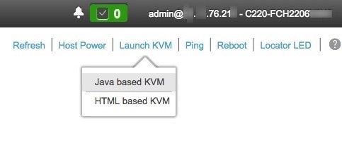
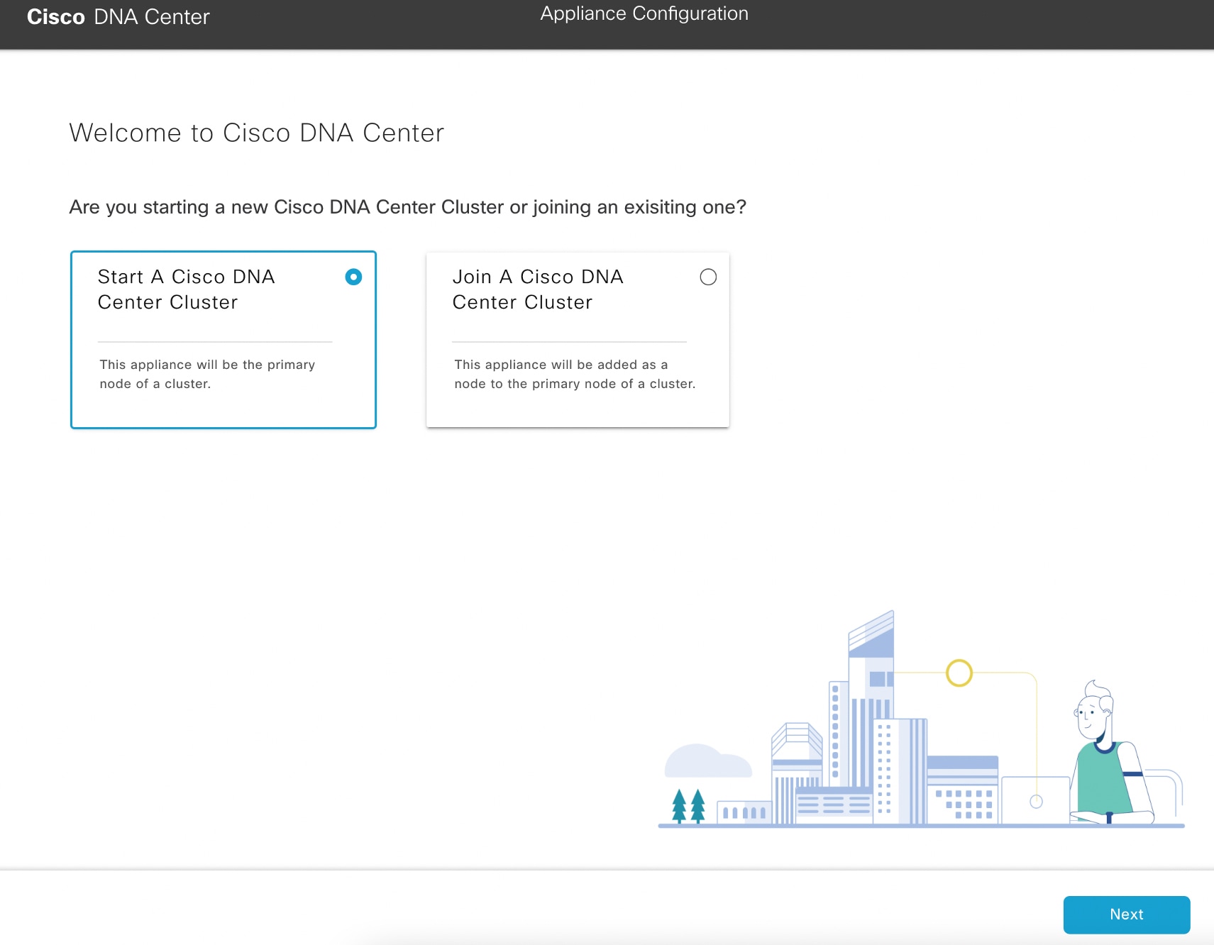
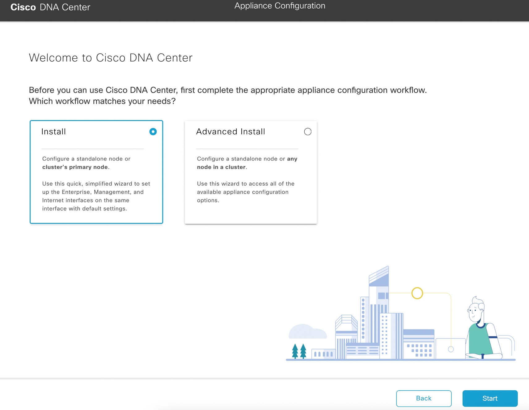
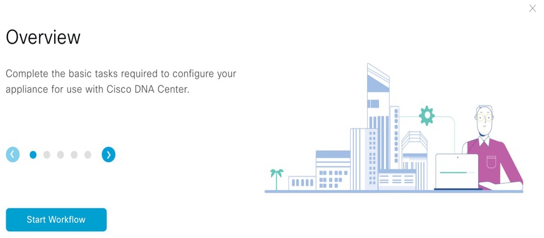
| 1. | Start the Install configuration wizard:
|
|||||||||||||||||||||||||
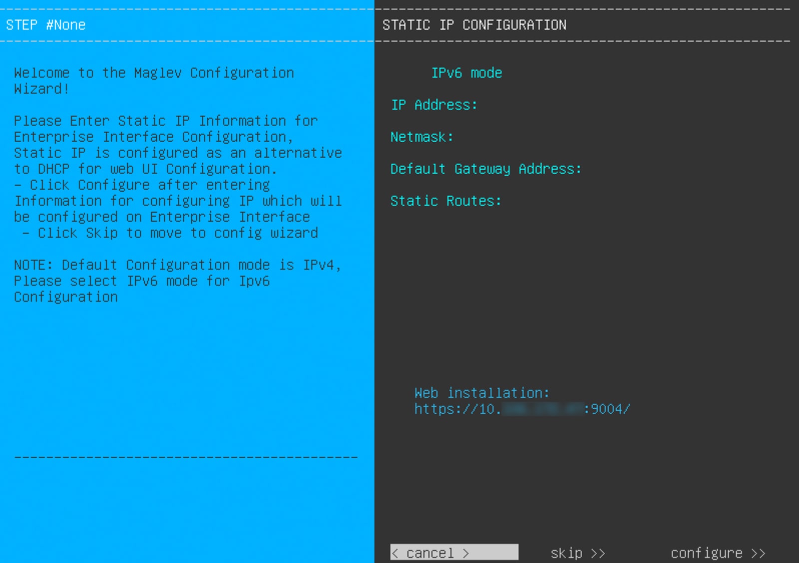
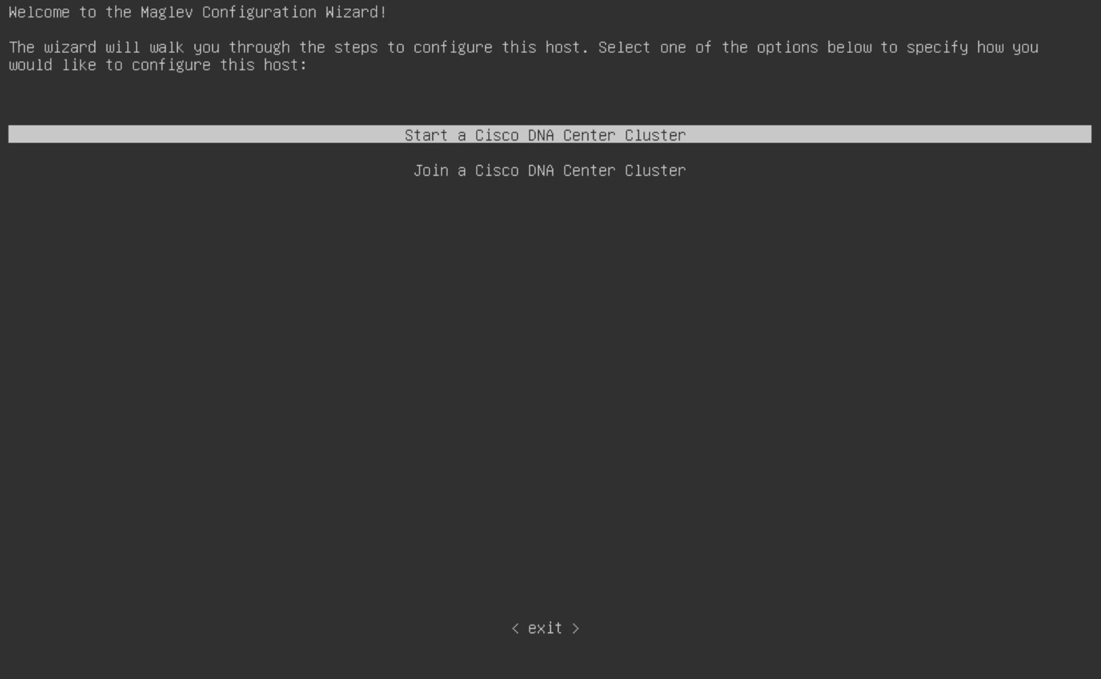
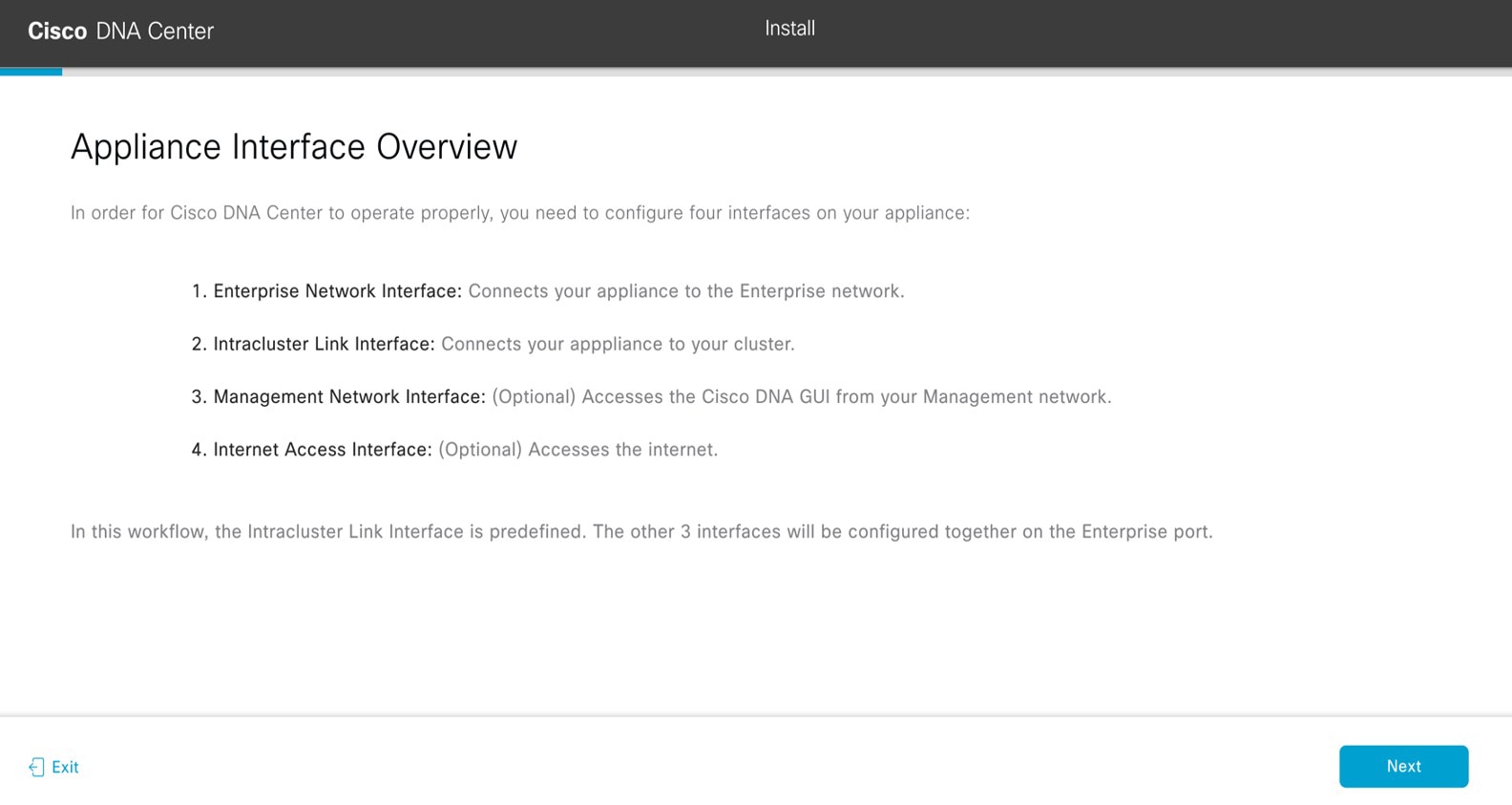
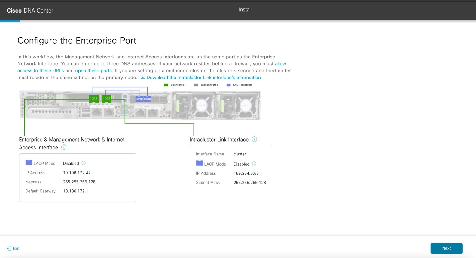
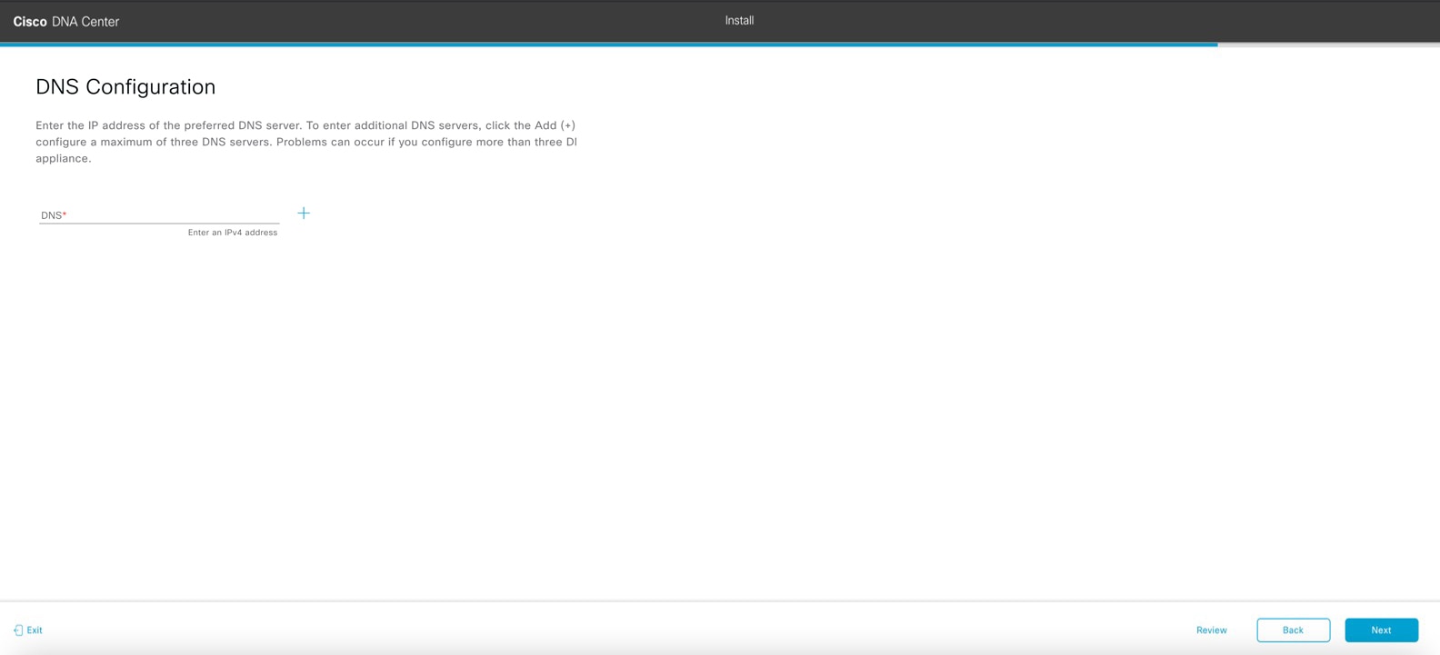
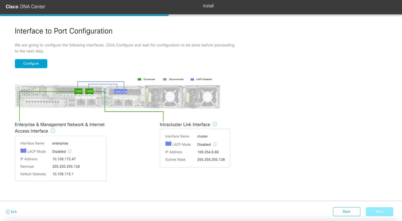
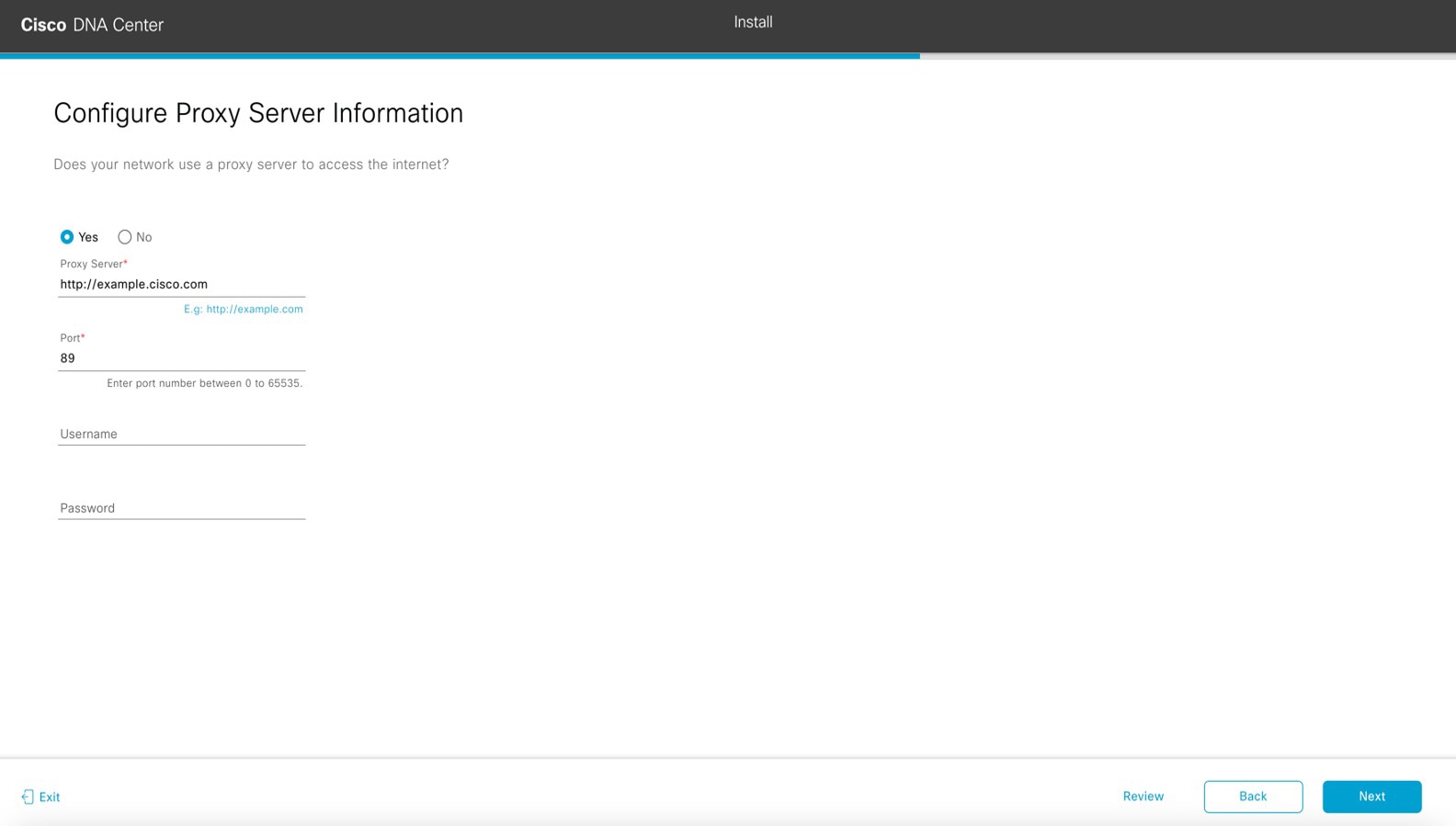
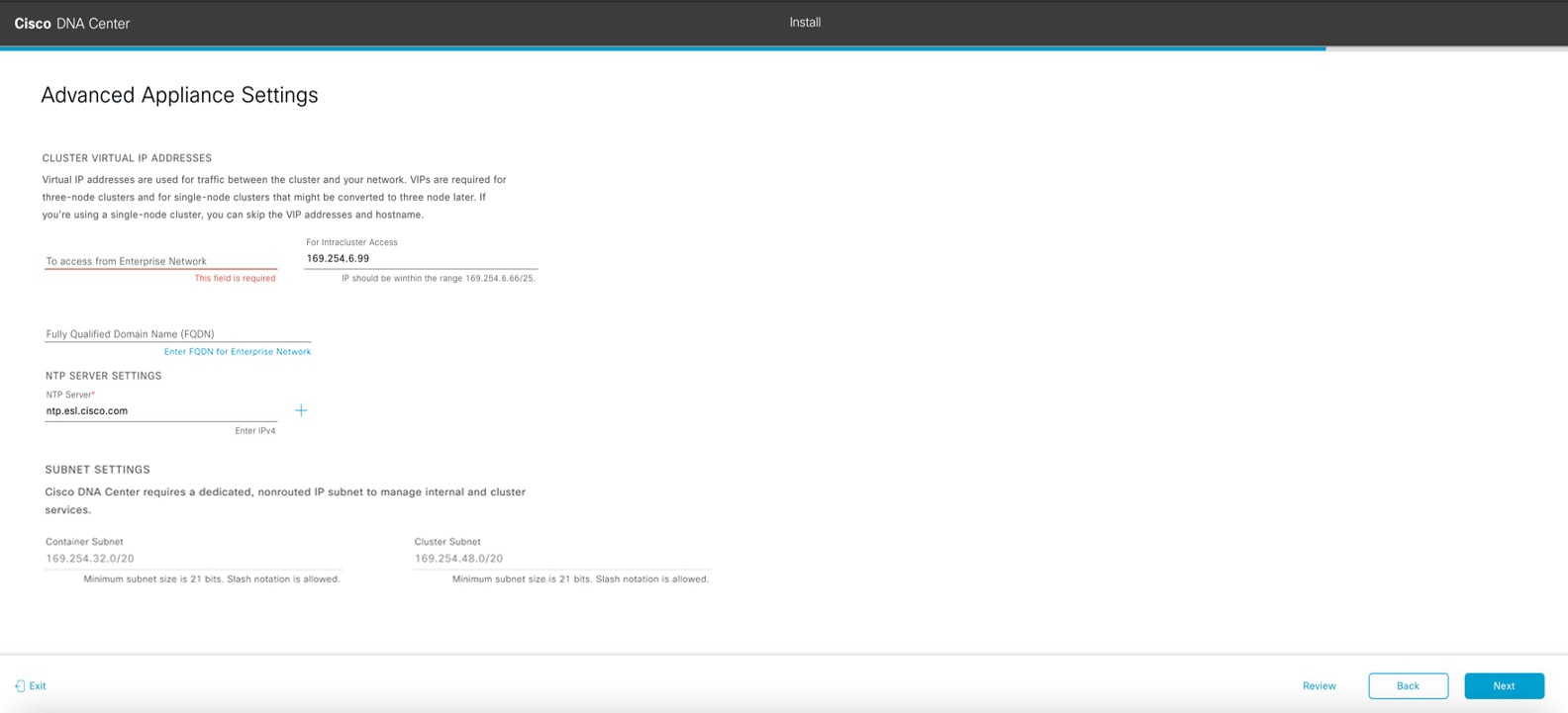
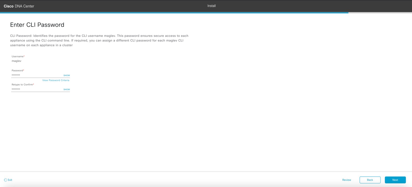
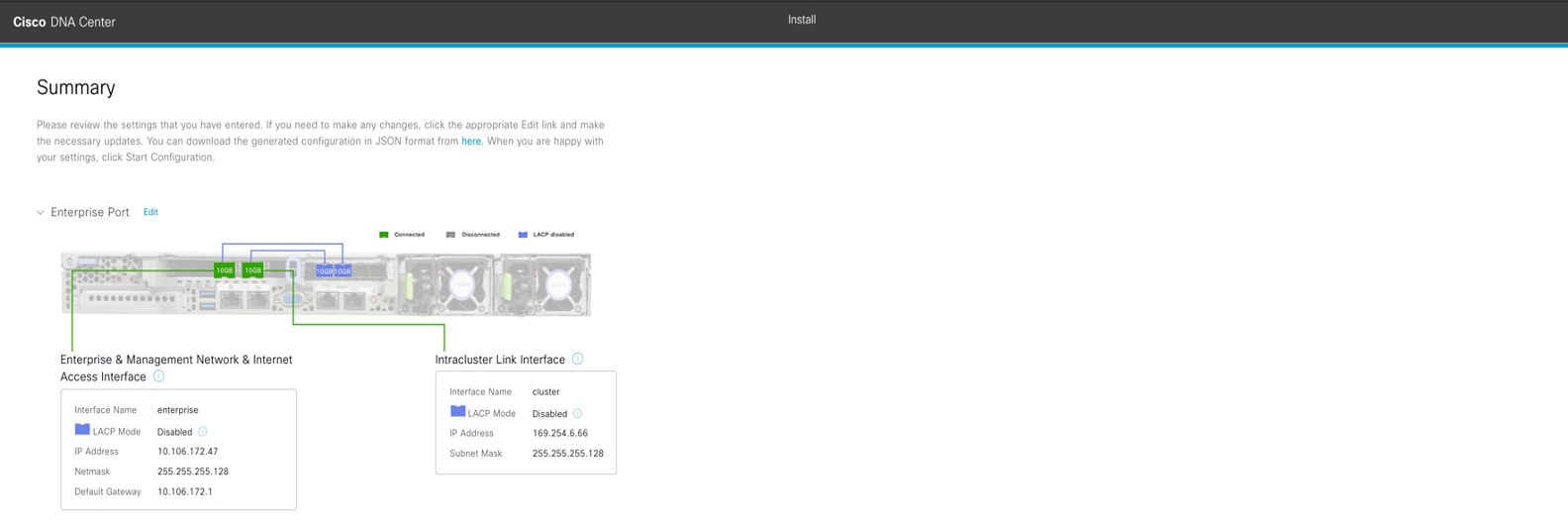
| 2. | Complete the Install configuration wizard:
|
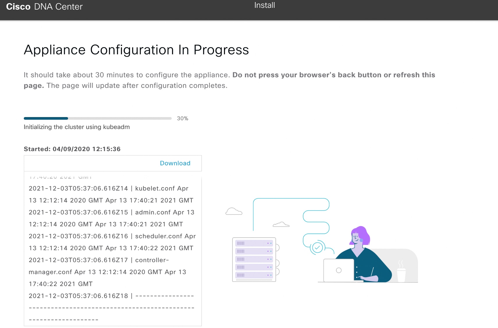
|||||||||||||||||||||||||
| 3. | After appliance configuration completes, click the copy icon in the Catalyst Center - Admin Credential area to copy the default admin superuser password. 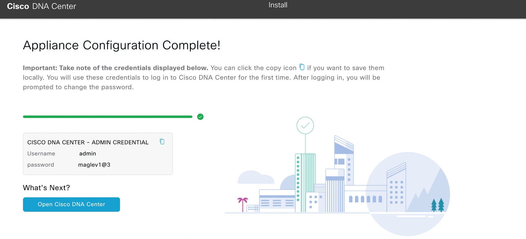
|
|||||||||||||||||||||||||
What to do next
As you are deploying this appliance in standalone mode, continue by performing the first-time setup: First-Time Setup Workflow.