|
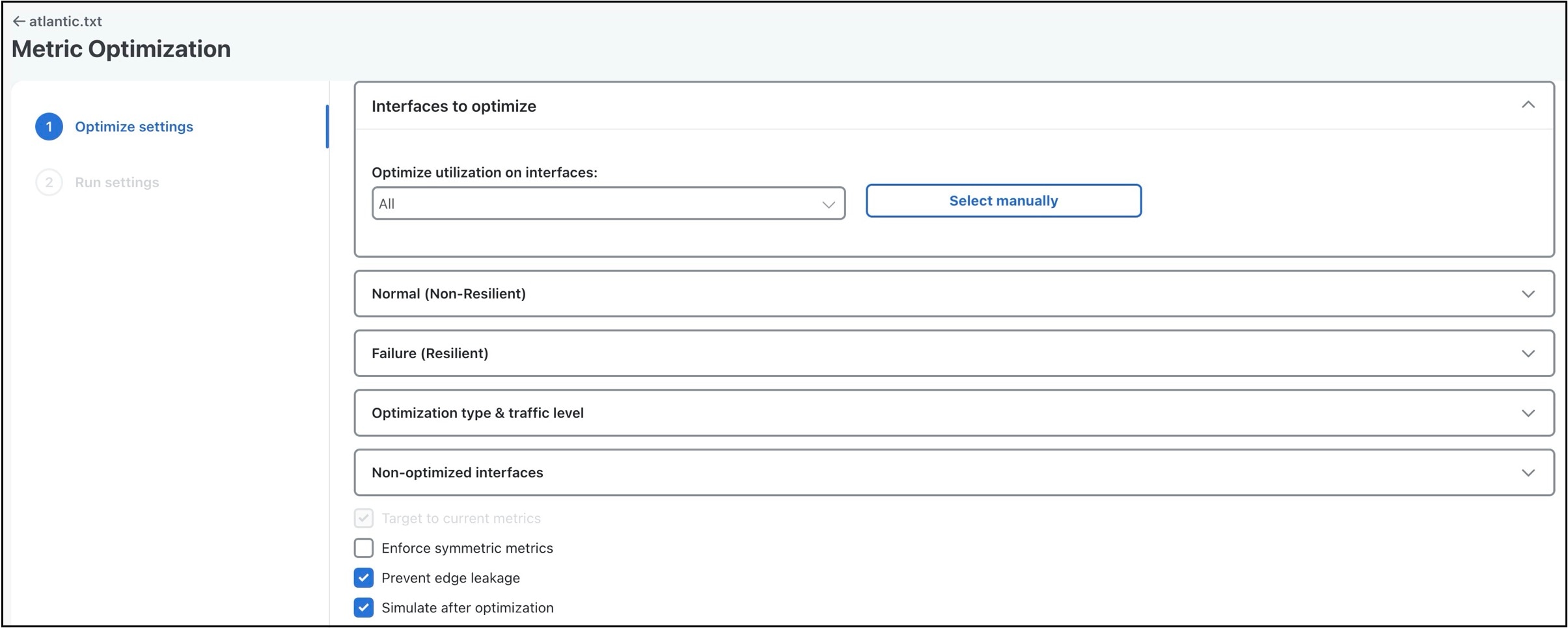
Interfaces to optimize
|
|
Optimize utilization on interfaces
|
By default, Cisco Crosswork Planning optimizes all interfaces. You can restrict the optimized interfaces using this option. Choose the Optimize utilization on interfaces value as Core, or select the interfaces manually using Select manually.
|
|
Normal (Non-Resilient) options
|
|
Minimize maximum interface utilization
|
This default is usually the primary objective, and concentrates on reducing the utilization of the interface with the highest
utilization.
|
|
Minimize # of interfaces with utilization > __ %
|
Often a small number of interfaces are bottlenecks in the network, and their utilizations cannot be reduced through rerouting.
However, it is still desirable to reduce the utilization of other, under-utilized interfaces. This option tries to reduce
all interface utilizations to below a specified utilization level, or, if this is not possible, to minimize the number of
interfaces over this level.
|
|
Minimize average latency
|
If after the optimizations flexibility is available in the choice of metrics, Cisco Crosswork Planning uses this flexibility to minimize the average latency of the routes across the network. This is not user-configurable and
is always on.
|
|
Enforce latency bounds
|
If checked, the choice of paths for each demand is restricted, if possible, to those demands with latency below the latency
bound.
|
|
Failure (Resilient) options
|
|
Minimize maximum interface utilization
|
If checked, Cisco Crosswork Planning selects metrics to minimize the maximum interface utilization over all interfaces and all failure scenarios. If unchecked,
only normal operation is optimized, and the remainder of the failure section is ignored.
|
|
Minimize # of interfaces with utilization > __ %
|
The number of interfaces with utilization (under any failure scenario) above a specified percentage is minimized.
|
|
Enforce no-failure utilization bound
|
If unchecked, maximum failure utilization is minimized with no consideration for utilization under normal operation. It is
often convenient to check this option and place a bound on the utilization under normal operation, which Metric Optimization
then satisfies, if possible.
|
|
Failure sets
|
This option determines the failure scenarios over which optimization is performed. You can select any combination of failures:
All unprotected circuits, SRLGs, nodes, sites, ports, port circuits, parallel circuits, and external endpoint members.
|
|
Optimization type & traffic level options
|
|
Optimization type
|
Cisco Crosswork Planning can perform global or incremental metric optimizations.
-
Global—Creates optimal routes from scratch, and targets the old metrics afterward. Because Cisco Crosswork Planning can choose routes globally, this option tends to perform better under some circumstances, particularly when the target routes
are poorly chosen. However, global optimization typically takes longer than incremental optimization.
-
Incremental—Uses the current routes as a basis from which improvements can be made. The target routes are not changed as
radically as when using global optimizations, and therefore the number of metric changes from the metric targets is typically
much smaller when using the incremental option.
|
|
Set metrics on interfaces
|
By default, Cisco Crosswork Planning sets or changes metrics on any of the core interfaces in the network to achieve its optimization goals. Alternatively, as
provided by this option, Metric optimization restricts metric changes to the following interfaces: all, core, interfaces selected
manually.
|
|
Traffic level
|
The traffic level over which the optimization is performed.
|
|
Non-optimized Interfaces options
|
|
Non-optimized Interfaces
|
For those interfaces that are not optimized, you can set the following:
|
|
Other options
|
|
Target to current metrics
|
There are many sets of metrics that will result in equivalent sets of routes. (Doubling all metrics, for example, does not
change routes.) Cisco Crosswork Planning selects between these sets of metrics by metric targeting. Metrics can be selected to match as closely as possible the current
metrics in the network. This simplifies the changeover from one set of metrics to the next.
|
|
Enforce symmetric metrics
|
This option sets the two metrics on each interface of each circuit equal to one another. This constraint can reduce optimization
performance. However, it ensures that demands from A (source) to Z (destination) and from Z to A (in the core) take the same
path, and so the chances of a session between A and Z being interrupted by a failure is minimized.
|
|
Prevent edge leakage
|
This default option restricts how Cisco Crosswork Planning can change demand routes. If a demand starts by routing only through the core, or from the edge through the core to the edge,
this option prevents the routing from being changed so that it routes through the edge in the middle of its path. This is
usually a desired routing policy restriction.
|
|
Simulate after optimization
|
This default option performs a simulation analysis after optimizing metrics. The simulation analysis allows a detailed view,
for example, of the utilizations under failure resulting from the new metric settings.
|

 Feedback