Optimize capacity
You can set optimization parameters to relieve network congestion and augment capacity. You start by defining a maximum utilization threshold for a specified set of interfaces, and then layering additional options that operate on Layer 3 and across failure sets.
 Note |
Some of the optimizer options are mutually exclusive; for example, if you tell the optimizer to create port circuits, it cannot create parallel circuits at the same time. Other options are complementary; for example, you can specify the creation of parallel circuits and new adjacencies together. |
Procedure
|
Step 1 |
Open the plan file (see Open plan files). It opens in the Network Design page. |
||||
|
Step 2 |
From the toolbar, choose any of the following options:
|
||||
|
Step 3 |
From the Circuits panel, choose the circuits you want the optimizer to consider. Decide on the Layer 3 optimization options to use. The options are described in Optimization options. You can upgrade all existing circuits or a subset of these circuits. If you want to allow the upgrade of just certain circuits, indicate those circuits to be modified. This is useful if you want to limit your upgrades to a certain geographical location in the network. To create new port circuits or parallel circuits, choose one of the following options:
|
||||
|
Step 4 |
(Optional) Override the defaults for how upgraded circuits and new objects are tagged. |
||||
|
Step 5 |
Click Next. |
||||
|
Step 6 |
(Optional) In the Optimization objective section, choose the options to provide additional capacity planning. Describe the cost for the various elements in your design. In the Failure sets section, choose the failure sets, as required. For more information, see Advanced optimization options. |
||||
|
Step 7 |
(Optional) Specify the maximum number of threads. By default, the optimizer tries to set this value to the optimal number of threads based on the available cores. |
||||
|
Step 8 |
Click Next. |
||||
|
Step 9 |
On the Run Settings page, choose whether to execute the task now or schedule it for a later time. Choose from the following Execute options:
|
||||
|
Step 10 |
(Optional) If you want to display the result in a new plan file, specify a name for the new plan file in the Display results section.
|
||||
|
Step 11 |
Click Submit to create the capacity planning optimization reports. |
Cisco Crosswork Planning routes the traffic and looks at the utilization threshold, and any other optimization parameters you specified. If you have specified any advanced options, the optimizer takes into account whether it makes sense to upgrade existing circuits or set up new adjacencies, and considers capacity increments, cost options, and feasibility limits.
After running an optimization, you can look at the summary report to see what the optimizer did to remove congestion. The key metric to look at is the Total Capacity Added (Mb/s). For details, see Analyze optimization reports.
Example
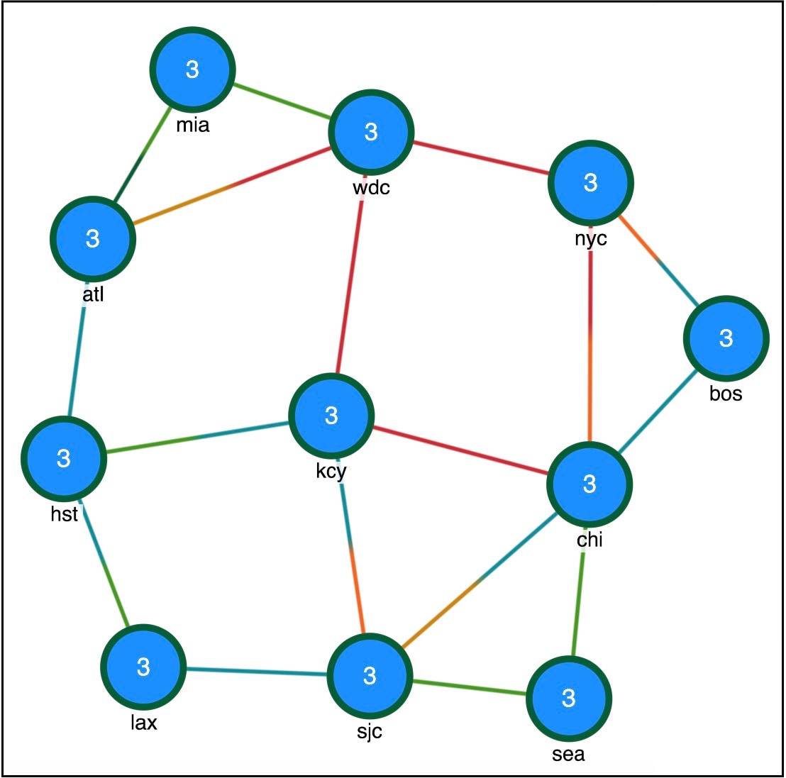
Design before optimization shows an example of a network design before optimization, where extra demands were placed on the network. As a result, you can see congested interfaces in red.
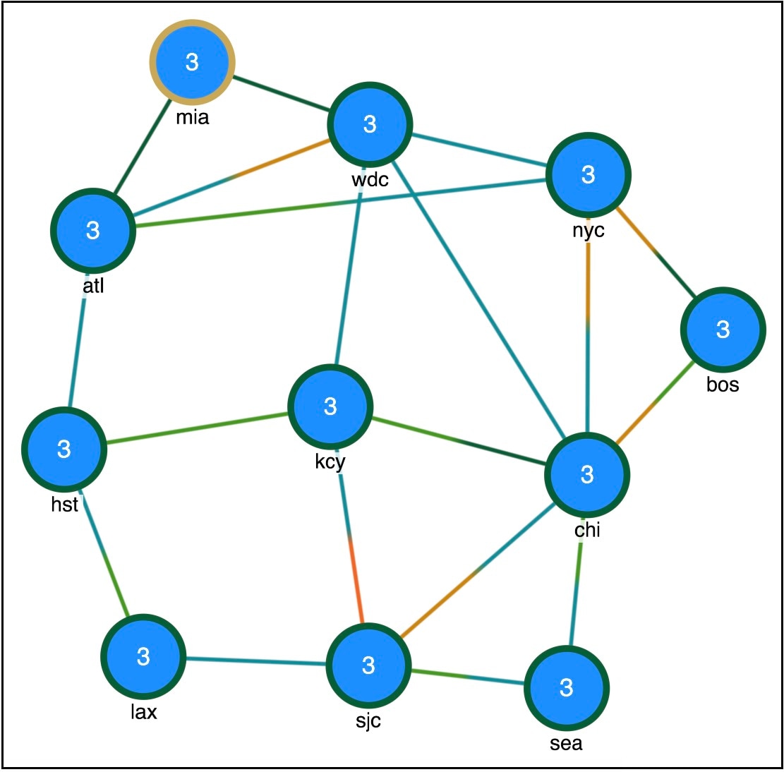
Design after optimization shows the design after optimization using the following parameters (For the remaining options, the default values are used.):
-
Maximum interface utilization—100%
-
Capacity increment—2488 Mbps
-
Circuits—Upgrade All circuits and Create Port circuits (LAGs)
-
Create new adjacencies—Restrict new adjacencies between all nodes
-
Failure sets—Circuits
In this case, the optimizer proposes to set up two new adjacencies:
-
One between Atlanta (atl) and New York City (nyc)
-
One between Washington, D.C. (wdc) and Chicago (chi)
Optimization options
You have several Layer 3 options for capacity planning. These parameters tell the optimizer what your preferences are in terms of utilization thresholds, capacity increments, and whether to upgrade existing circuits, create new adjacencies between nodes, create port circuits, or create parallel circuits.
|
Option |
Description |
|---|---|
|
Interface utilization & capacity |
|
|
Maximum interface utilization |
Defines the maximum utilization threshold that you want to use for all interfaces in the network. By default, the capacity planning optimizer sets the threshold at 100% congestion. However, for future planning purposes, you might want to set the utilization to a lower number, such as 90%. |
|
Capacity increment |
Defines the bandwidth increment value (that is, the allowed capacity increment). You can think of this value as the capacity of the ports. The default is 100000 Mb/s. |
|
Use capacity of existing LAG members |
Augments capacity based on the capacity already defined in the existing LAG Members instead of using the Capacity increment. |
|
Circuits |
|
|
Upgrade Circuits |
You can upgrade all circuits, or just a subset of circuits to reduce congestion. If you want to allow the upgrade of just certain circuits, select those circuits to be modified. This is useful if you want to limit your upgrades to a certain geographical location in the network. By default, none of the circuits are selected. |
|
Create
|
|
|
|
|
Adjacencies |
|
|
Restrict new adjacencies between nodes |
By default, the optimizer does not create new adjacencies. If you specify a set of candidate nodes for it to use, the optimizer proposes new adjacencies. The optimizer restricts a new adjacency between the specified candidate nodes. For example, you might require that only core nodes be directly connected. In this case, specify only core nodes as your candidate nodes. |
|
Maximum number of new adjacencies |
Specifies the maximum number of adjacencies to create between candidate nodes. By default, this is an unbounded number. |
|
Set IGP metric of new interfaces to
|
|
|
|
|
Tag upgraded circuits with |
Defines tags for any upgraded circuits. By default, the optimizer tags upgraded circuits with the label CapacityOpt::Upgraded. |
|
Tag new objects with |
Defines tags for any new objects the optimizer creates. By default, the optimizer tags upgraded circuits with the label CapacityOpt::New. |
Advanced optimization options
Use the advanced optimization options to:
-
Choose whether to optimize for capacity or cost.
-
Define what failure scenarios to consider.
When you run the optimizer, the tool generates a report on the overall cost, including the cost of the added ports, and recommends the most cost-efficient solution.
|
Option |
Description |
|---|---|
|
Optimization objective |
|
|
Minimize capacity |
Minimizes the capacity that is added to your network. This is the default option. |
|
Minimize cost |
Select this option to run the optimization with the objective of reducing the overall cost when adding new capacity. Click
|
|
Failure sets |
Choose the options that you want the optimizer to consider (Circuits, Nodes, Sites, and so on). Entries appear dimmed if they are not available in your design plan. |
|
Maximum number of threads |
Specify the maximum number of threads. By default, the optimizer tries to set this value to the optimal number of threads based on the available cores. |
Parallel circuits design example
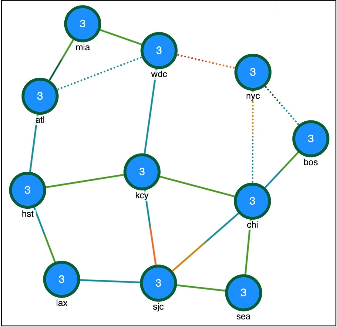
Adding parallel circuits to increase capacity shows the first design in this chapter with parallel circuits added to increase capacity. In this case, the optimizer proposes four sets of parallel circuits as indicated by the dotted lines:
-
One between Atlanta (atl) and Washington, D.C. (wdc)
-
One between Washington, D.C. (wdc) and New York City (nyc)
-
One between New York City (nyc) and Chicago (chi)
-
One between New York City (nyc) and Boston (bos)
 Feedback