Simulate IGP Routing Protocol

This chapter describes options for simulating an IGP. Cisco Crosswork Planning can simulate IS-IS, OSPF, and EIGRP, as well as supports multi-topology routing for IS-IS and OSPF IGPs.

This section contains the following topics:

IGP process ID

An IGP process ID is used to differentiate between multiple instances of the same IGP running on a router. This allows you to have separate IGP configurations for different purposes within the same router.

In Cisco Crosswork Planning, you can specify IGP process ID to an IGP protocol. Also, each interface can be associated with an IGP process ID.

Configure IGP process ID

Follow these steps to create, delete, or edit an IGP process ID.

Procedure


Step 1

Open the plan file (see Open plan files). It opens in the Network Design page.

Step 2

From the toolbar, choose Actions > Edit > IGP process protocols.

The IGP process protocols page opens.

Step 3

Configure IGP process ID.

Figure 1. Configure IGP process ID
  1. To create IGP process ID, click Add icon, enter the name, and select the required IGP protocol. Click Save to save the IGP process ID.

  2. To edit an IGP process ID, click the Edit button of the IGP process ID that you want to edit. Update the values and then click Save.

  3. To delete an IGP process ID, select the IGP process ID that you want to delete, and then click Delete icon or use the Delete button.


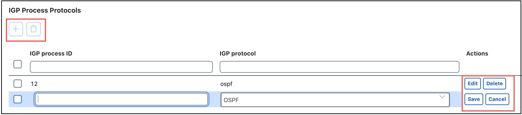
Associate interfaces with an IGP process ID

Follow these steps to associate each interface with an IGP process ID.

Procedure


Step 1

From the Interfaces table, select one or more interfaces for which you want to add the IGP process ID.

Step 2

Click Edit icon and then click the Advanced tab.

Note


If you are editing a single interface, you can also use the > Edit option under the Actions column.

Step 3

In the IGP panel, enter the value in the IGP process ID field.

Step 4

Click Save.


OSPF and IS-IS

OSPF and IS-IS simulations are identical with the following exceptions:

  • OSPF routing uses OSPF areas, if specified. By default, all interfaces are assigned area zero.

  • IS-IS routing uses IS-IS levels, if specified. By default, all interfaces are set to Level 2. Interfaces can belong to Level 1, Level 2, or both. If both, then an alternate metric for Level 1 can also be specified.

OSPF area simulation

OSPF area membership can be specified per interface. For instructions, see Set OSPF area membership.

The two interfaces on each circuit must belong to the same area. Area names can be any string. Area zero, the backbone area, must be denoted by ‘‘0’’, ‘‘0.0.0.0’’, or an empty string. Cisco Crosswork Planning simulates the OSPF area routing configuration in which the areas import Link State Advertisements (LSAs) from the backbone. A demand from a source node to a destination node in a different area will only be routed if it can reach the destination by passing through the source area, directly to area zero, and from there directly to the destination area.

By default, all nodes in a single AS are assumed to belong to a single OSPF area. Nodes are assigned to areas, as follows:

  • If OSPF areas are not defined for interfaces, all nodes are assumed to be in the same area.

  • Each interface can be assigned to only one OSPF area. Note that each node can be assigned to one or more areas.

  • If a node has an interface in an OSPF area, the node is assigned to that area.

  • An Area Border Router (ABR) is a node that belongs to both area 0 and other OSPF areas.

Set OSPF area membership

To specify OSPF area membership, do the following:

Procedure

Step 1

Open the plan file (see Open plan files). It opens in the Network Design page.

Step 2

In the Network Summary panel on the right side, select one or more interfaces from the Interfaces table.

Step 3

Click Edit icon.

Note


If you are editing a single interface, you can also use the > Edit option under the Actions column.

Step 4

Click the Advanced tab.

Step 5

In the IGP panel, enter the required value in the OSPF area field.

Step 6

Click Save.


IS-IS multi-level simulation

By default, IS-IS interfaces are assigned to Level 2, though you can assign them to Level 1 or to both Levels 1 and 2. For instructions, see Set IS-IS multi-level simulation.

  • The IGP metric defines the Level 1 metric for interfaces in Level 1, in Level 2, or in both Level 1 and 2 if these have equal metrics. However, you can change the Level 1 metric.

  • If an interface is in both Level 1 and Level 2 with uneven metrics, the IGP metric defines the Level 2 metric and the Level 1 metric defines the Level 1 metric.

The IS-IS level is listed in the ISIS level column of the Interfaces table, and the Level 1 metric is listed in the Metric ISIS level 1 column.

By default, all nodes in a single AS are assumed to belong to a single IS-IS level. Nodes are assigned to levels, as follows:

  • Each node can be assigned to one or more levels.

  • Two Level 1 nodes are placed in different areas if any route between them (under normal operation) passes through a Level 2 node.

  • A node is assigned to a single Level 2 area if there is at least one interface that is Level 2, or both Level 1 and Level 2.

  • A node is assigned to one of potentially multiple Level 1 areas if any interface is Level 1, or both Level 1 and Level 2.

  • An ABR is a node belonging to both the Level 2 area and another IS-IS area.

Set IS-IS multi-level simulation

To set IGP metrics, IS-IS levels, and Level 1 metrics, do the following:

Procedure

Step 1

Open the plan file (see Open plan files). It opens in the Network Design page.

Step 2

In the Network Summary panel on the right side, select one or more interfaces from the Interfaces table.

Step 3

Click Edit icon.

Note


If you are editing a single interface, you can also use the > Edit option under the Actions column.

Step 4

To set the IGP metric, enter its value in the IGP metric field.

Step 5

To set IS-IS multi-level simulation, click the Advanced tab.

In the IGP panel:

  1. Enter the IGP process ID.

  2. Select the level from the IS-IS level drop-down list.

  3. In the Level 1 metric field, enter the metric value.

Step 6

Click Save.


EIGRP

The IGP Metric value for each interface is not used when EIGRP routing is selected. Instead, EIGRP uses the following formula to derive total feasible distance (total cost) from a node to a destination subnet.

path metric to destination = (10,000/(bandwidth) + (delay) * 256
  • The bandwidth is the minimum interface Capacity value along the path. This is in Mbps. For each interface, if there is no Capacity value, the Capacity Sim value is used instead.

  • The delay is the sum of the interface delays in 10s of microseconds. This is calculated by taking the sum of the EIGRP Delay values and dividing this sum by 10.

You can set this delay in the EIGRP delay field of an interface's Edit window. Here, the value is in microseconds.

If EIGRP delay is not set, Cisco Crosswork Planning uses 10 as the delay in the preceding calculation, which means 10 "10s of microseconds.". For example, if there are eight interfaces, each with an EIGRP Delay value of 15, the delay used in the calculation is (8 x 15) / 10 = 120 / 10 = 12.

Demands show the EIGRP path metric of the path over which they flow in the Path metric column.

Simulate IGP multipath

By default, demands are split equally between all paths from a route of equal distance to the destination, and there is no ECMP limit.

You can specify a maximum number of ECMP paths. In this case, demands transiting through a router are distributed among the available paths up to this maximum ECMP value. Paths are chosen by lowest next-hop IP address, which is the interface IP address for IGP or the destination IP address for LSPs. Paths with no IP address are chosen last.

Follow these steps to configure ECMP.

Procedure


Step 1

Open the plan file (see Open plan files). It opens in the Network Design page.

Step 2

In the toolbar, click Network options or choose Actions > Edit > Network options.

The Network options page opens.

Step 3

Click the Protocols tab.

Step 4

In the IGP section, enter the maximum number of ECMPs in the Max ECMP paths field. A 0 (zero) means there is no limit.

Step 5

Click Save.


Exclude ABR nodes

To exclude the nodes while entering or exiting the domain, do the following:

Procedure


Step 1

Open the plan file (see Open plan files). It opens in the Network Design page.

Step 2

From the toolbar, choose Actions > Edit > Node ABR exclusions.

The Node ABR exclusions page opens. The Node column displays the A and Z end. The Exclude node column displays the node that is excluded.

Step 3

To add a node that has to be excluded:

  1. Click Add icon.

  2. In the Node and Exclude node sections, specify the details of the node and the node that needs to be excluded, respectively.

  3. Click Save.

Step 4

To delete an ABR node:

  1. Select the row that you want to delete.

  2. Click Delete icon.


Configure IGP simulation

Follow these steps to configure IGP simulation.

Procedure


Step 1

Open the plan file (see Open plan files). It opens in the Network Design page.

Step 2

In the toolbar, click Network options or choose Actions > Edit > Network options.

The Network options page opens.

Step 3

Click the Protocols tab.

Step 4

Under the IGP section, choose the appropriate protocol from the Protocol drop-down list.

Step 5

Click the Simulation tab.

Step 6

Select an option for Redistribute routes across IGP process.

The options include:

  • No IGP redistribution

  • Shortest exit

  • Shortest path

Step 7

The Multiple IGP ABRs option is disabled by default. This option is helpful if you want to apply tie breakers for ECMP paths based on BGP ID, IP address, and host name respectively.

Step 8

Click Save.


Simulate multi-topology routing

Cisco Crosswork Planning supports simulation of multi-topology routing. Interfaces can be assigned to one or more IGPs. Demands and LSPs can be assigned to a specific IGP, and will only route through interfaces belonging to that IGP. This multi-topology simulation uses these rules:

  • When an interface is common to more than one topology, all IGP properties of the interface (including the metric) must be the same in both topologies.

  • The IGPs must be defined to be of the same type, for example, OSPF or IS-IS. This is not a restriction in practice unless either the OSPF topology or the IS-IS topology uses multiple areas.

  • Demands and LSPs defined with a specific topology can only route over circuits belonging to that topology. A circuit belongs to a topology if either one of its interfaces does.

  • Demands and LSPs with no defined topology have no restrictions on routing. They are routed using the default topology, to which all interfaces belong.

Configure topologies

To create, rename, or delete topologies, do the following:

Procedure


Step 1

Open the plan file (see Open plan files). It opens in the Network Design page.

Step 2

From the toolbar, choose Actions > Edit > Topologies. The Topologies page opens.

Step 3

To create a new topology:

  1. Click Add icon.

  2. Enter the topology name.

  3. Click the Save button.

Step 4

To delete a topology:

  1. Select the row containing the topology you want to delete.

  2. Click the Delete button in the selected row or click Delete icon.


Add topologies to objects

To associate demands or LSPs with topologies, do the following. Once you have associated the topologies, you can view them by showing the Topology column in the respective tables (use the Show/hide table columns icon (Show/Hide Columns Icon).

Before you begin

Create the topologies. For details, see .

Procedure


Step 1

Open the plan file (see Open plan files). It opens in the Network Design page.

Step 2

In the Network Summary panel on the right side, select one or more demands or LSPs from their respective tables.

Step 3

Click Edit icon.

Step 4

Select the desired topology or topologies, as follows.

  1. From the Topology drop-down list, select the desired topology. You can associate one topology to each demand or LSP.

    In case of LSPs, this drop-down is available under the Advanced tab.

  2. Click Save.

By selecting from a similar Topology drop-down list, you can also add a topology to LSP meshes when creating them.