System Management Configuration Guide, Cisco Catalyst IE3x00 Rugged, IE3400 Heavy Duty, and ESS3300 Series Switches

PDF

System Management Configuration Guide, Cisco Catalyst IE3x00 Rugged, IE3400 Heavy Duty, and ESS3300 Series Switches

NTP to PTP time conversion

Want to summarize with AI?

Log in

Describes a feature that allows you to use Network Time Protocol (NTP) as a time source for PTP, enabling customers to correlate data between PTP networks and enterprise data centers running NTP.


NTP to PTP time conversion is a synchronization feature that allows you to use Network Time Protocol (NTP) as a time source for PTP. This feature enables customers who require very precise synchronization within a site to use PTP, and to use NTP across sites where precision is not required. It also allows customers to correlate data generated in their PTP network with data in their enterprise data centers running NTP.

NTP time synchronization background

NTP is the traditional method of synchronizing clocks across packet based networks. NTP uses a two-way time transfer mechanism between a time source and an end device. NTP is capable of synchronizing a device within a few hundred milliseconds across the Internet and within a few milliseconds in a tightly controlled LAN.

Note

Beginning with the Cisco IOS XE Dublin 17.12.x release, Cisco Catalyst IE3100 Rugged Series Switches are supported for NTP to PTP time conversion.

Industrial network time synchronization implementation

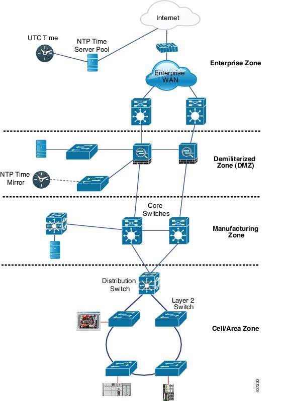
The example illustrates an industrial network based on the Industrial Automation and Control System Reference Model. The enterprise zone and demilitarized zone run NTP, and the manufacturing zone and cell/area zone run PTP with NTP as the time source. The switch with the NTP to PTP conversion feature can be either the Layer 2 Switch or the Distribution Switch in the Cell/Area Zone.
Grandmaster boundary clock hybrid

A grandmaster boundary clock hybrid (GMC-BC) is a PTP clock type that

  • adds grandmaster clock functionality to Cisco PTP, enabling the switch to be a time source as well as forward time,

  • provides an NTP time source for PTP networks by converting NTP to PTP,

  • acts as a boundary clock (BC), a multi-port device in which a single-port GMC is connected to a virtual port on the BC, and

  • switches between acting like a GMC when the GMC-BC is the primary GMC and acting like a BC when the GMC-BC is a backup.

Redundant GMC-BC configuration

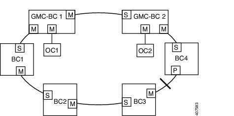
The GMC-BC ensures that all devices on the PTP network remain synchronized in a failover scenario. This figure shows a PTP network with redundant GMC-BCs where GMC-BC 1 is the grandmaster clock, and GMC-BC 2 is both backup GMC and BC.

Figure 1. Redundant GMC-BC configuration
The figure illustrates a PTP network with two redundant Grandmaster Boundary Clocks (GMC-BCs), where GMC-BC 1 serves as the primary grandmaster clock and GMC-BC 2 functions as both a backup grandmaster clock and boundary clock, ensuring synchronization during failover scenarios.

In a network with two GMC-BCs, the secondary GMC-BC can synchronize to both the NTP reference and the PTP reference at the same time, so the secondary GMC-BC can immediately take over when the primary GMC-BC fails. The GMC-BC instantly updates the time during a switchover.


Clock manager

A clock manager is a component in the Cisco NTP to PTP software architecture that

  • keeps track of the various time services and selects the clock that actively provides time

  • notifies the time services of important changes, including state changes, leap seconds, or daylight saving time, and

  • selects the NTP or manually set clock first. If NTP is not active, it selects PTP and the real-time clock.

Time service selection process

This table shows the results of the clock selection process.

Table 1. Time service selection

NTP (Active) or Manually Set

PTP (Active)

Real-Time Clock

Selected Output

True

Don't care

Don't care

NTP or Manually Set

False

True

Don't care

PTP

False

False

True

Real-Time Clock

In general, the clock manager ensures that the time displayed in the Cisco IOS XE commands show ptp clock and show clock match. The show clock command always follows this priority, but there are two corner cases where the show ptp clock time may differ:

  • The switch is either a TC or a BC, and there is no other active reference on the network. To preserve backward compatibility, the TC and BC never take their time from the clock manager; they only obtain their time from the network's PTP GMC. If there is no active PTP GMC, then the time displayed in the show clock and the show ptp clock command output may differ.

  • The switch is a syntonizing TC, a BC with a time recipient port, or a GMC-BC with time recipient port, and the time provided by the PTP GMC does not match the time provided by NTP or the user (that is, manually set). In this case, the PTP clock must forward the time from the PTP GMC. If the PTP clock does not follow the PTP GMC, then the PTP network will end up with two different time bases, which would break any control loops or sequence of event applications using PTP.

This table shows how the Cisco IOS XE and PTP clocks behave given the various configurations. Most of the time, the two clocks match. Sometimes, the two clocks are different. These configurations are highlighted in the table.

Table 2. Expected time flow

IOS XE Clock Configuration

PTP Clock Configuration

IOS XE Clock Source

PTP Clock Source

Calendar

PTP BC, E2E TC, or GMC-BC in BC Mode

PTP

PTP

Manual

PTP BC, E2E TC, or GMC-BC in BC Mode

Manual

PTP

NTP

PTP BC, E2E TC, or GMC-BC in BC Mode

NTP

PTP

Calendar

GMC-BC in GM Mode

Calendar

Calendar

Manual

GMC-BC in GM Mode

Manual

Manual

NTP

GMC-BC in GM Mode

NTP

NTP