Describes common topologies and use cases for implementing PTP over DLR in network environments.
PTP over DLR topologies are network configurations that enable precision time protocol implementation across device level ring networks. It supports various grandmaster clock placement scenarios for different operational requirements and provides fault tolerance through DLR ring recovery mechanisms.
Common PTP over DLR use cases
You can use PTP over DLR in a variety of different topologies for different purposes. This section provides information for two common use cases and topologies.
Single ring topology with grandmaster clock off ring:
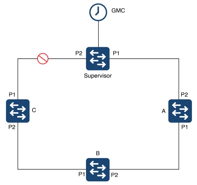
The preceding illustration depicts a single-ring topology with the GMC off the ring and connected to the supervisor. The supervisor operates in transparent clock mode. The ring has no breaks in it, and, as a result, the supervisor blocks all traffic on Port 2 (P2) except for control traffic. The supervisor and DLR-enabled devices A, B, and C, are all in transparent clock mode. The configuration prevents devices on the ring from seeing changes within their PTP system when the Layer 1 infrastructure has a fault. It also causes DLR to open up P2.
In the illustration, a fault occurs between devices A and B. Before the fault, device C would receive PTP messages on P1 because P2 is blocking. After the fault, P2 on the supervisor goes to forwarding state. As a result, the device will receive PTP messages from the supervisor on P2.
If the supervisor is a device with multiple VLANs using normal transparent clock operation, it is not possible to support the forwarding of PTP messages on different VLANs. Configure the DLR supervisor node in transparent clock mode with multiple VLAN support. This configuration allows the use of multiple VLANs while maintaining a single time source on the ring.
DLR ring connected to spanning tree protocol topology:
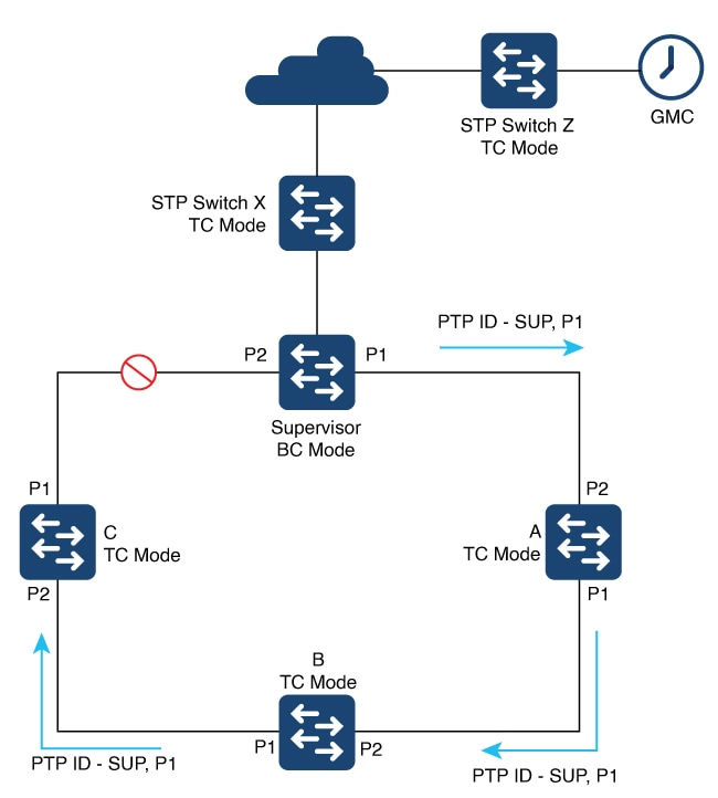
The preceding diagram shows a single DLR ring used with the Spanning Tree Protocol (STP), with the GMC off the ring. The supervisor operates in BC mode, and the ring nodes and STP switches operate in TC mode.
When operating as a boundary clock (BC), all TCs and ordinary clocks view the supervisor as the PTP parent—specifically, the parent and the port number that transmits the PTP messages. In the diagram, the PTP messages are sent from Port 1. TCs and ordinary clocks use the PTP ID to recognize the PTP parent based on the PTP clock ID of the supervisor, the port number (for example, P1), and other attributes. All devices are synchronized to the PTP parent based on messages transmitted from P1.
When a fault occurs in the ring, the supervisor recognizes the fault and opens P2. This action allows all traffic to use that port, enabling the topology to reconverge and restoring connectivity to devices. The supervisor sends PTP messages with the port number set to P2 instead of P1. The change causes the ordinary clocks (the end devices) to perceive a change of the PTP parent. End devices may resynchronize with the new PTP parent, and this transition can be disruptive.
Configure the DLR supervisor node in TC mode with support for multiple VLANs to overcome this limitation. Doing so would allow the use of multiple VLANs while maintaining a single time source on the ring. Because all nodes in the DLR ring are in TC mode, the parent ID and parent port number do not change when a failure occurs in the ring.