Cisco Application Centric Infrastructure (ACI) Design Guide
Available Languages
Bias-Free Language
The documentation set for this product strives to use bias-free language. For the purposes of this documentation set, bias-free is defined as language that does not imply discrimination based on age, disability, gender, racial identity, ethnic identity, sexual orientation, socioeconomic status, and intersectionality. Exceptions may be present in the documentation due to language that is hardcoded in the user interfaces of the product software, language used based on RFP documentation, or language that is used by a referenced third-party product. Learn more about how Cisco is using Inclusive Language.
- US/Canada 800-553-2447
- Worldwide Support Phone Numbers
- All Tools
 Feedback
 Feedback
Table of Contents
Cisco Nexus 9000 Series Hardware
Cisco Application Policy Infrastructure Controller (APIC)
Fabric with Mixed Hardware or Software
Fabric with Different Spine Types
Fabric with Different Leaf Switch Types
Fabric with Different Software Versions
Leaf and Spine Switch Functions
Multi-tier Design Considerations
Per Leaf RBAC (Role-based Access Control)
Virtual Port Channel Hardware Considerations
Hardware Compatibility Between vPC Pairs
Placement of Outside Connectivity
Border Leaf Switches with VRF-lite, SR/MPLS Handoff and GOLF
Using Border Leaf Switches for Server Attachment
Limit the use of L3Out for Server Connectivity
Service Leaf Switch Considerations
In-band and out-of-band Management Connectivity
Multiple Locations Data Centers Design Considerations
Fabric Infrastructure (Underlay) Design
Choosing the Leaf Switch Forwarding Profile
Common Reserved VLANs on External Devices
Hardening the Infrastructure VLAN
BGP Autonomous System Number Considerations
BGP Route-Reflector Placement Considerations
Network Time Protocol (NTP) configuration
In-Band and Out-of-Band Management
In-band Connectivity to the Outside
In-band Management Configuration
Out-of-band Management Configuration
Management Connectivity for VMM Integration
In-band Management Requirements for Telemetry
IS-IS Metric for Redistributed Routes
Configuring the Fabric Infrastructure for Faster Convergence
Cisco APIC Design Considerations
Port tracking and Cisco APIC Ports
In-Band and Out-of-Band Management of Cisco APIC
Internal IP Address Used for Apps
Summary of Cisco APIC design considerations
Cisco ACI Objects Design Considerations
Fabric Infrastructure Configurations
Objects with Overlapping Names in Different Tenants
Connectivity Instrumentation Policy
Fabric-access Policy Configuration Model
Defining VLAN Pools and Domains
Attachable Access Entity Profiles (AAEPs)
Understanding VLAN Use in Cisco ACI and to Which VXLAN They Are Mapped
Domain and EPG VLAN Validations
Cisco Discovery Protocol, LLDP, and Policy Resolution
Port Channels and Virtual Port Channels
Static Port Channel, LACP Active, LACP Passive
Configuration for Faster Convergence with VPCs
Port Channels and Virtual Port Channels Configuration Model in Cisco ACI
Interaction with Cisco APIC Ports
Loop Mitigation Features Overview
LLDP for Mis-Cabling Protection
Mis-Cabling Protocol (MCP) Overview
Link Aggregation Control Protocol (LACP) Suspend Individual Ports
Interface-level Control Plane Policing (CoPP)
Spanning Tree Protocol Considerations
Endpoint Move Dampening, Endpoint Loop Protection, and Rogue Endpoint Control
Rogue Endpoint Control Exceptions
Summary Best Practices for Layer 2 Loop Mitigation
Network-centric and Application-centric Designs (and EPGs Compared with ESGs)
Implementing a Network-centric Topology
Default Gateway for the Servers
Assigning Servers to Endpoint Groups
Layer 2 Connectivity to the Outside with Network Centric Deployments
Using VRF Unenforced Mode or Preferred Groups or vzAny with Network Centric Deployments
Using ESGs to Create the Equivalent of Multiple Preferred Groups
Implementing a Tenant Design With Segmentation Using EPGs or ESGs (Application-centric)
Adding EPGs to Existing Bridge Domains
Merging Bridge Domains and Subnets (with Flood in Encapsulation)
Using Endpoint Security Groups
Adding Filtering Rules with Contracts and Firewalls with vzAny and Service Graph Redirect
Default Gateway (Subnet) Design Considerations
Bridge Domain Subnet, SVI, Pervasive Gateway
Subnet Configuration: Under the Bridge Domain and Why Not Under the EPG
VRF Instances and Bridge Domains in the Common Tenant
VRF Instances in the Common Tenant and Bridge Domains in User Tenants
VRF Ingress Versus VRF Egress Filtering Design Considerations
Bridge Domain Design Considerations
Bridge Domain Configuration for Migration Topologies
BPDU Handling in the Bridge Domain
Using Hardware-Proxy to Reduce Flooding
Layer 2 Multicast and IGMP Snooping in the Bridge Domain
Bridge Domain Enforcement Status
Summary of Bridge Domain Recommendations
Configuring Trunk Ports with Nexus 9300-EX and Newer
Configuring Trunk Ports with First Generation Leaf switches
EPGs, Bridge Domains, and VLAN mapping
EPGs, Physical and VMM Domains, and VLAN Mapping on a Specific Port (or Port Channel or vPC)
Internal VLANs on the Leaf Switches: EPGs and Bridge Domains Scale
Assigning Physical Hosts to EPGs
Using the Application Profile EPG
Assigning Hosts to EPGs from the Attachable Access Entity Profile (AAEP)
Assigning Virtual Machines to EPGs
EPG Configuration Workflow with VMM Integration
Connecting EPGs to External Switches
Using EPGs to connect Cisco ACI to External Layer 2 Networks
EPG and Fabric Access Configurations for Multiple Spanning Tree
Minimize the scope of Spanning Tree Topology Changes
Using EPGs to Connect Cisco ACI to External Layer 2 Networks Using vPCs
Contracts Design Considerations
Security Contracts are ACLs Without IP Addresses
Permit, Deny, Redirect, and Copy
Concept of Direction in Contracts
Understanding the Bidirectional and Reverse Filter Options
Configuring a Stateful Contract
Configuring a Single Contract Between EPG/ESGs
Contracts and Filters in the Common Tenant
Setting the Contract Scope Correctly
Saving Policy-CAM Space with Compression
Pros and Cons of using Contracts from Tenant Common
Unenforced VRF Instances, Preferred Groups, vzAny
Contracts and Filtering Rule Priorities
Resolution and Deployment Immediacy of VRF Instances, Bridge Domains, EPGs, and Contracts
EPG Resolution Immediacy and Deployment Immediacy Options
EPG Resolution Immediacy and Deployment Immediacy Considerations for Virtualized Servers
Endpoint Learning Considerations
Local Endpoint Learning on the Leaf Switches
Endpoint Aging with Multiple IP Addresses for the Same MAC Address
Endpoint Retention Policy at the Bridge Domain and VRF Level
Dataplane Learning from ARP packets
When and How to disable Remote Endpoint Learning (for Border Leaf Switches)
Floating IP Address Considerations
When and How to Disable IP Dataplane Learning
Stale Entries and Endpoint Announce Delete
Server Connectivity and NIC Teaming Design Considerations
Design Model for IEEE 802.3ad with a vPC
NIC Teaming Configurations for Non-Virtualized Servers
Server Active/Active (802.3ad Dynamic Link Aggregation) Teaming with vPC
NIC Teaming Active/Active non-Port Channel-based (non-vPC)
NIC Teaming Configurations for Virtualized Servers (Without the Use of VMM Integration)
NIC Teaming Configurations for Virtualized Servers with VMM Integration
CDP and LLDP in the Policy Group Configuration
Configuring Teaming using the Cisco ACI VMM Integration
Teaming Options with VMM Integration
Choosing between Policy-Group type Access Leaf Port and vPC
Using LACP Between the Virtualized Host and the Cisco ACI Leaf switches
Teaming Configuration with Servers Not Directly Attached to the Cisco ACI Leaf switches
UCS connectivity with Fabric Interconnect
Designing External Layer 3 Connectivity
The evolution of L3Out: VRF-lite, GOLF and SR/MPLS handoff
Layer 3 Outside (L3Out) and External Routed Networks
L3Out Router ID Considerations
Route Announcement Options for the Layer 3 Outside (L3Out)
Route Map Handling Differences Between OSPF, EIGRP and BGP
External Network (External EPG) Configuration Options
Advertisement of Bridge Domain Subnets
Add L3Out SVI Subnets to the External EPG
Bidirectional Forwarding Detection (BFD) for L3Out
Considerations for Multiple L3Outs
External EPGs Have a VRF Scope
Using Dynamic L3Out EPG Classification (DEC)
Considerations When Using More Than Two Border Leaf Switches
Using BGP for External Connectivity
BGP Autonomous System (AS) number
Supported Combinations for Transit Routing
Loop Prevention in Transit Routing Scenarios
Quality of Service (QoS) In Cisco ACI
Quality of Service for Traffic Going to an IPN
VRF Sharing Design Considerations
Inter-Tenant and Inter-VRF Communication
Inter-VRF Communication using EPGs
Inter-VRF Communication using ESGs
Configuration of the Subnet: When to Enter the Subnet Under the EPG
Policy Enforcement with Inter-VRF Traffic
Special Considerations and Restrictions for VRF Sharing Designs
Reducing the Cisco APIC Upgrade Time
Reducing Traffic Disruption During Upgrades
Graceful Upgrades Versus Graceful Insertion and Removal
Features That Must be Disabled Before an Upgrade or a Downgrade
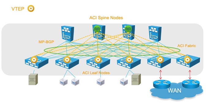
Cisco Application Centric Infrastructure (Cisco ACI™) technology enables you to integrate virtual and physical workloads in a programmable, multi-hypervisor fabric to build a multiservice or cloud data center. The Cisco ACI fabric consists of discrete components connected in a spine and leaf switch topology that it is provisioned and managed as a single entity.
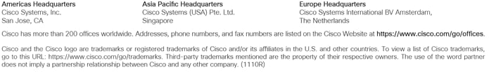
This document describes how to implement a fabric such as the one depicted in Figure 1.
The design described in this document is based on the following reference topology:
● Two spine switches interconnected to several leaf switches
● Top-of-Rack (ToR) leaf switches for server connectivity, with a mix of front-panel port speeds: 1/10/25/40/50/100/200/400-Gbps
● Physical and virtualized servers dual-connected to the leaf switches
● A pair of border leaf switches connected to the rest of the network with a configuration that Cisco ACI calls a Layer 3 Outside (L3Out) connection
● A cluster of three Cisco Application Policy Infrastructure Controllers (APICs) dual-attached to a pair of leaf switches in the fabric
The network fabric in this design provides the following main services:
● Connectivity for physical and virtual workloads
● Partitioning of the fabric into multiple tenants, which may represent departments or hosted customers
● The ability to create shared-services partitions (tenant) to host servers or virtual machines whose computing workloads provide infrastructure services such as Network File System (NFS) and Microsoft Active Directory to the other tenants
● Capability to provide dedicated or shared Layer 3 routed connections to the tenants present in the fabric
A Cisco ACI fabric can be built using a variety of Layer 3 switches that, while compatible with each other, differ in terms of form factors and ASICs to address multiple requirements.
You can find the list of available leaf and spine switches at the following URL:
https://www.cisco.com/c/en/us/products/switches/nexus-9000-series-switches/models-comparison.html
This document is based on features that are present in Cisco ACI release 6.0(1g).
Cisco ACI can integrate with every virtualized server using physical domains and the EPG Static Port configuration for "static binding" (more on this later) and with many external controllers using direct API integration, which is called Virtual Machine Manager (VMM) integration. Cisco APIC can integrate using VMM integration with VMware ESXi hosts with VMware vSphere, Hyper-V servers with Microsoft SCVMM, RedHat Virtualization, Kubernetes, OpenStack, OpenShift, and more. Cisco ACI 5.1(1) and later releases can integrate with VMware NSX-T Data Center (NSX).
The integration using static binding doesn’t require any special software version, whereas for the integration using Virtual Machine Manager you need specific Cisco ACI versions to integrate with specific Virtual Machine Manager versions.
VMware ESXi hosts with VMware vSphere 7.0 can be integrated with Cisco ACI release 4.2(4o) or later using VMM. VMware ESXi hosts integrate with Cisco ACI using the VMware vSphere Distributed Switch (vDS).
Note: This design guide explains design considerations related to teaming with specific reference to the VMM integration with VMware vSphere and it does not include the integration with VMware NSX-T.
For information about the support for virtualization products with Cisco ACI, see the ACI Virtualization Compatibility Matrix.
For more information about integrating virtualization products with Cisco ACI, see the virtualization documentation.
Cisco Nexus 9000 Series Hardware
For a list of available Cisco ACI Nexus 9000 series switches, see Cisco Nexus 9000 Series Switches.
This section provides some clarification about the naming conventions used for the leaf and spine switches referred to in this document:
● N9K-C93xx refers to the Cisco ACI leaf switches
● N9K-C95xx refers to the Cisco modular chassis
● N9K-X97xx refers to the Cisco ACI spine switch line cards
The trailing -E and -X signify the following:
● -E: Enhanced. This refers to the ability of the switch to classify traffic into endpoint groups (EPGs) based on the source IP address of the incoming traffic.
● -X: Analytics. This refers to the ability of the hardware to support analytics functions. The hardware that supports analytics includes other enhancements in the policy CAM, in the buffering capabilities, and in the ability to classify traffic to EPGs.
● -F: Support for MAC security.
● -G: Support for 400 Gigabit Ethernet.
For simplicity, this document refers to any switch without a suffix or with without the -X suffix as a first generation switch, and any switch with -EX, -FX, -GX, or any later suffix as a second generation switch.
Note: The Cisco ACI leaf switches with names ending in -GX have hardware that is capable of operating as either a spine or leaf switch. The software support for either option comes in different releases. For more information, see Cisco Nexus 9300-GX Series Switches Data Sheet.
For port speeds, the naming conventions are as follows:
● G: 100M/1G
● P: 1/10-Gbps Enhanced Small Form-Factor Pluggable (SFP+)
● T: 100-Mbps, 1-Gbps, and 10GBASE-T copper
● Y: 10/25-Gbps SFP+
● Q: 40-Gbps Quad SFP+ (QSFP+)
● L: 50-Gbps QSFP28
● C: 100-Gbps QSFP28
● D: 400-Gbps QSFP-DD
● E: 800-Gbps
For the taxonomy, see Taxonomy for Cisco Nexus 9000 Series Part Numbers.
For more information about Cisco Nexus 400 Gigabit Ethernet switches hardware (which includes Cisco ACI leaf and spine switches switches), see 400G Data Center and Cloud Networking.
In Cisco ACI, all workloads connect to leaf switches. The leaf switches used in a Cisco ACI fabric are Top-of-the-Rack (ToR) switches. A number of leaf switch choices differ based on function:
● Port speed and medium type
● Buffering and queue management: All leaf switches in Cisco ACI provide advanced capabilities to load balance traffic more precisely, including dynamic packet prioritization, to prioritize short-lived, latency-sensitive flows (sometimes referred to as mouse flows) over long-lived, bandwidth-intensive flows (also called elephant flows). The newest hardware also introduces more sophisticated ways to keep track and measure elephant and mouse flows and prioritize them, as well as more efficient ways to handle buffers.
● Policy CAM size and handling: The policy CAM is the hardware resource that allows filtering of traffic between EPGs. It is a TCAM resource in which Access Control Lists (ACLs) are expressed in terms of which EPG (security zone) can talk to which EPG (security zone). The policy CAM size varies depending on the hardware. The way in which the policy CAM handles Layer 4 operations and bidirectional contracts also varies depending on the hardware. -FX and -GX leaf switches offer more capacity compared with -EX and -FX2.
● Multicast routing support in the overlay: A Cisco ACI fabric can perform multicast routing for tenant traffic (multicast routing in the overlay).
● Support for analytics: The newest leaf switches and spine switch line cards provide flow measurement capabilities for the purposes of analytics and application dependency mappings.
● Support for link-level encryption: The newest leaf switches and spine switch line cards provide line-rate MAC security (MACsec) encryption.
● Scale for endpoints: One of the major features of Cisco ACI is the endpoint database, which maintains the information about which endpoint is mapped to which Virtual Extensible LAN (VXLAN) tunnel endpoint (VTEP), in which bridge domain, and so on.
Ability to change the allocation of hardware resources, such as to support more Longest Prefix Match entries, or more policy CAM entries, or more IPv4 entries. This concept is called "tile profiles," and it was introduced in Cisco ACI 3.0. For more information, see Cisco APIC Forwarding Scale Profiles and Verified Scalability Guide.
The -GX hardware can be deployed both as leaf or as a spine switch, and in case of high density 100 or 400 ports leaf switches you can use breakout cables to connect lower speed ports. For more information, see Nexus 9300 400 GE Switches.
For more information about the differences between the Cisco Nexus® 9000 series switches, see the following documents:
● https://www.cisco.com/c/en/us/products/switches/nexus-9000-series-switches/models-comparison.html
The spine switches are available in several form factors both for modular switches as well as for fixed form factors. Cisco ACI leaf switches with name ending in -GX have hardware that can operate both as spine and as leaf switch.
The differences among spine switches with different hardware are as follows:
● Port speeds
● Support for analytics: although this capability is primarily a leaf switch function and it may not be necessary in the spine switch, in the future there may be features that use this capability in the spine switch.
● Support for link-level encryption and for CloudSec. For information, see Cisco ACI Multi-Site Configuration Guide, Release 2.0(x).
● Support for Cisco ACI Multi-Pod and Cisco ACI Multi-Site: Refer to the specific documentation on Cisco ACI Multi-Pod and Cisco ACI Multi-Site, including the respective release notes, for more details.
At the time of this writing, the speed of ports used for spine switches was moving more and more to 400 Gigabit Ethernet density and the same -GX hardware can be used as a leaf or spine switch. For more information, see Nexus 9300 400 GE Switches.
Note: For information about Cisco ACI Multi-Site hardware requirements, see Cisco ACI Multi-Site Hardware Requirements Guide, Release 2.0(x).
The Cisco ACI fabric forwards traffic based on host lookups (when doing routing): all known endpoints in the fabric are programmed in the spine switches. The endpoints saved in the leaf switch forwarding table are only those that are used by the leaf switch in question, thus preserving hardware resources at the leaf switch. As a consequence, the overall scale of the fabric can be much higher than the individual scale of a single leaf switch.
The spine switch models also differ in the number of endpoints that can be stored in the spine proxy table, which depends on the type and number of fabric modules installed.
You should use the verified scalability limits for the latest Cisco ACI release and see how many endpoints can be used per fabric. See the Verified Scalability Guide for your release.
According to the verified scalability limits, the following spine switch configurations have the indicated endpoint scalabilities:
● Max. 450,000 Proxy Database Entries with four (4) fabric line cards
● Max. 180,000 Proxy Database Entries with the fixed spine switches
The above numbers represent the sum of the number of MAC, IPv4, and IPv6 addresses; for instance, in the case of a Cisco ACI fabric with fixed spine switches, this translates into:
● 180,000 MAC-only EPs (each EP with one MAC only)
● 90,000 IPv4 EPs (each EP with one MAC and one IPv4)
● 60,000 dual-stack EPs (each EP with one MAC, one IPv4, and one IPv6)
The number of supported endpoints is a combination of the capacity of the hardware tables, what the software allows you to configure, and what has been tested.
Refer to the Verified Scalability Guide for a given release and to the Capacity Dashboard in the Cisco APIC GUI for this information.
Detailed guidelines about which type of transceivers and cables you should use is outside of the scope of this document. The Transceiver Compatibility Matrix is a great tool to help with this task: https://tmgmatrix.cisco.com/
Cisco Application Policy Infrastructure Controller (APIC)
The Cisco APIC is the point of configuration for policies and the place where statistics are archived and processed to provide visibility, telemetry, and application health information and enable overall management of the fabric. The controller is a physical appliance based on a Cisco UCS® rack server with two interfaces for connectivity to the leaf switches. The Cisco APIC is also equipped with Gigabit Ethernet interfaces for out-of-band management.
For more information about the Cisco APIC models, see Cisco Application Policy Infrastructure Controller Data Sheet.
Note: A cluster may contain a mix of different Cisco APIC models; however, the scalability will be that of the least powerful cluster member.
Note: The naming of the Cisco APICs, such as M3 or L3, is independent of the UCS series names.
Fabric with Mixed Hardware or Software
Fabric with Different Spine Types
In Cisco ACI, you can mix new and old generations of hardware for the spine and leaf switches. For instance, you could have first-generation hardware leaf switches and new-generation hardware spine switches, or vice versa. The main considerations with spine hardware are as follows:
● Uplink bandwidth between leaf and spine switches
● Scalability of the spine proxy table (which depends primarily on the type of fabric line card that is used in the spine)
● Cisco ACI Multi-Site requires spine switches based on the Cisco Nexus 9500 platform cloud-scale line cards to connect to the intersite network
You can mix spine switches of different types, but the total number of endpoints that the fabric supports is the minimum common denominator.
Fabric with Different Leaf Switch Types
When mixing leaf switches of different hardware types in the same fabric, you may have varying support of features and different levels of scalability.
In Cisco ACI, the processing intelligence resides primarily on the leaf switches, so the choice of leaf switch hardware determines which features may be used (for example, multicast routing in the overlay, or FCoE). Not all leaf switches provide the same hardware capabilities to implement all features.
Cisco APIC pushes the managed object to the leaf switches regardless of the ASIC that is present. If a leaf switch does not support a given feature, it raises a fault. For multicast routing you should ensure that the bridge domains and Virtual Routing and Forwarding (VRF) instances configured with the feature are deployed only on the leaf switches that support the feature.
Fabric with Different Software Versions
The Cisco ACI fabric is designed to operate with the same software version on all the APICs and switches. During upgrades, there may be different versions of the OS running in the same fabric.
If the leaf switches are running different software versions, the following behavior applies: Cisco APIC pushes features based on what is implemented in its software version. If the leaf switch is running an older version of software and the Cisco APIC does not understand a feature, the Cisco APIC will reject the feature; however, the Cisco APIC may not raise a fault.
For more information about which configurations are allowed with a mixed OS version in the fabric, see the software and firmware installation and upgrade guides.
Running a Cisco ACI fabric with different software versions is meant to be just a temporary configuration to facilitate upgrades, and minimal or no configuration changes should be performed while the fabric runs with mixed OS versions.
You can connect fabric extenders (FEXes) to the Cisco ACI leaf switches; the main purpose of doing so should be to simplify migration from an existing network with fabric extenders. If the main requirement for the use of FEX is the Fast Ethernet port speeds, you may want to consider the Cisco ACI leaf switch models with -G or -T in the product name, such as Cisco Nexus N9K-C9348GC-FXP, N9K-C93108TC-FX, N9K-C93108TC-FX-24, N9K-C93108TC-EX, N9K-C93108TC-EX-24, N9K-C93216TC-FX2, and N9K-93108TC-FX3P.
To connect a FEX to a Cisco ACI leaf switch, you must assign a FEX ID to each FEX, and this number has leaf scope, so the same FEX ID can be re-used on a different leaf switch.
A FEX can be connected to Cisco ACI using a port channel with what is known as a straight-through topology, and vPCs can be configured between hosts and the FEX, but not between the FEX and Cisco ACI leaf switches.
A FEX can be connected to leaf switch front-panel ports as well as converted downlinks (since Cisco ACI release 3.1).
A FEX has many limitations compared to attaching servers and network devices directly to a leaf switch. The main limitations as follows:
● No support for L3Out on a FEX
● No Rate limiters support on a FEX
● No Traffic Storm Control on a FEX
● No Port Security support on a FEX
● A FEX should not be used to connect routers or Layer 4 to Layer 7 devices with service graph redirect
● The use in conjunction with microsegmentation works, but if microsegmentation is used, then Quality of Service (QoS) does not work on FEX ports because all microsegmented traffic is tagged with a specific class of service. Microsegmentation and a FEX is a feature that at the time of this writing has not been extensively validated.
Support for FCoE on a FEX was added in Cisco ACI release 2.2. See Cisco Application Policy Infrastructure Controller, Release 2.2(1), Release Notes.
When using Cisco ACI with a FEX, you want to verify the verified scalability limits; in particular, the limits related to the number of ports multiplied by the number of VLANs configured on the ports (commonly referred to as P, V). For more information, see the Verified Scalability Guide for your release.
With regard to scalability, you should keep in mind the following points:
● The total scale for VRF instances, bridge domains (BDs), endpoints, and so on is the same whether you are using FEX attached to a leaf switch or whether you are connecting endpoints directly to a leaf switch. This means that, when using FEX, the amount of hardware resources that the leaf switch provides is divided among more ports than just the leaf switch ports.
● The total number of VLANs that can be used on each FEX port is limited by the maximum number of P,V pairs that are available per leaf switch for host-facing ports on FEX. For the latest supported scale numbers, see the Verified Scalability Guide.
● The maximum number of EPGs per FEX port is the maximum number of encapsulations per FEX port as specified in the Verified Scalability Guide.
● For the maximum number of FEXes per leaf switch, see the Verified Scalability Guide.
Note: For more information about which leaf switch is compatible with which fabric extender, refer to the following link:
For more information about how to connect a fabric extender to Cisco ACI, see Nexus 9000 Series Switch FEX Support.
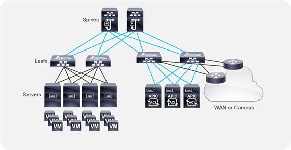
As of release 4.1, a Cisco ACI fabric can be built as a two-tier fabric or as a multi-tier (three-tiers) fabric.
Prior to Cisco ACI 4.1, the Cisco ACI fabric allowed only the use of a two-tier (spine and leaf switch) topology, in which each leaf switch is connected to every spine switch in the network with no interconnection between leaf switches or spine switches.
Starting from Cisco ACI 4.1, the Cisco ACI fabric allows also the use of two tiers of leaf switches, which provides the capability for vertical expansion of the Cisco ACI fabric. This is useful to migrate a traditional three-tier architecture of core-aggregation-access that have been a common design model for many enterprise networks and is still required today. The primary reason for this is cable reach, where many hosts are located across floors or across buildings; however, due to the high pricing of fiber cables and the limitations of cable distances, it is not ideal in some situations to build a full-mesh two-tier fabric. In those cases, it is more efficient for customers to build a spine-leaf-leaf switch topology and continue to benefit from the automation and visibility of Cisco ACI.
Leaf and Spine Switch Functions
The Cisco ACI fabric is based on a two-tier (spine and leaf switch) or three-tier (spine switch, tier-1 leaf switch and tier-2 leaf switch) architecture in which the leaf and spine switches provide the following functions:
● Leaf switches: These devices have ports connected to classic Ethernet devices, such as servers, firewalls, and router ports. Leaf switches are at the edge of the fabric and provide the VXLAN Tunnel Endpoint (VTEP) function. In Cisco ACI terminology, the IP address that represents the leaf switch VTEP is called the Physical Tunnel Endpoint (PTEP). The leaf switches are responsible for routing or bridging tenant packets and for applying network policies.
● Spine switches: These devices interconnect leaf switches. They can also be used to build a Cisco ACI Multi-Pod fabric by connecting a Cisco ACI pod to an IP network, or they can connect to a supported WAN device (see more details in the "Designing external layer 3 connectivity" section). Spine switches also store all the endpoints-to-VTEP mapping entries (spine switch proxies).
Within a pod, all tier-1 leaf switches connect to all spine switches, and all spine switches connect to all tier-1 leaf switches, but no direct connectivity is allowed between spine switches, between tier-1 leaf switches, or between tier-2 leaf switches. If you incorrectly cable spine switches to each other or leaf switches in the same tier to each other, the interfaces will be disabled. You may have topologies in which certain leaf switches are not connected to all spine switches (such as in stretched fabric designs), but traffic forwarding may be suboptimal in this scenario.
Up until Cisco ACI 3.1, fabric ports on leaf switches were hard-coded as fabric (iVXLAN) ports and could connect only to spine switches. Starting with Cisco ACI 3.1, you can change the default configuration and make ports that would normally be fabric links, be downlinks, or vice-versa. For more information, see Cisco Application Centric Infrastructure Fundamentals.
Note: For information about the optics supported by Cisco ACI leaf and spine switches, use the following tool:
https://tmgmatrix.cisco.com/home
Multi-tier Design Considerations
Only Cisco Cloudscale switches are supported for multi-tier spine and leaf switches.
● Spine: EX/FX/C/GX spine switches (Cisco Nexus 9332C, 9364C, and 9500 with EX/FX/GX line cards)
● Tier-1 leaf: EX/FX/FX2/GX except Cisco Nexus 93180LC-EX
● Tier-2 leaf: EX/FX/FX2/GX
Design considerations for multi-tier topology include the following:
● All switch-to-switch links must be configured as fabric ports. For example, Tier-2 leaf switch fabric ports are connected to tier-1 leaf switch fabric ports.
● A tier-2 leaf switch can connect to more than two tier-1 leaf switches, in comparison to a traditional double-sided vPC design, which has only two upstream switches. The maximum number of ECMP links supported by a tier-2 leaf switch to tier-1 leaf switch is 18.
● An EPG, L3Out, Cisco APIC, or FEX can be connected to tier-1 leaf switches or to tier-2 leaf switches.
● Tier-1 leaf switches can have both hosts and tier-2 leaf switches connected on it.
● Changing from a tier-1 to a tier-2 leaf switch and back requires decommissioning and recommissioning the switch.
● Multi-tier architectures are compatible with Cisco ACI Multi-Pod and Cisco ACI Multi-Site.
● Tier-2 leaf switches cannot be connected to remote leaf switches (tier-1 leaf switches).
● Scale: The maximum number of tier-1 leaf switches and tier-2 leaf switches combined must be less than or equal to the maximum number of leaf switches that have been validated for a given release. (400 per pod; 500 per Cisco ACI Multi-Pod as of Cisco ACI release 6.0(1)).
More information about Cisco ACI multi-tier can be found at the following link: https://www.cisco.com/c/en/us/solutions/data-center-virtualization/application-centric-infrastructure/white-paper-c11-742214.html
Per Leaf RBAC (Role-based Access Control)
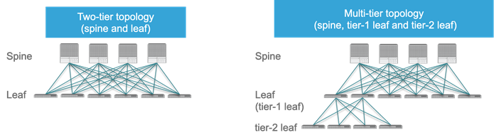
Up until Cisco ACI 5.0, a Cisco ACI fabric administrator could assign a tenant to a security domain to let users have read/write privilege for a specific tenant assigned to that security domain, but that RBAC feature was not applicable to specific leaf switch.
Starting from Cisco ACI 5.0, a leaf switch can be assigned to a security domain so that only specific users can configure leaf switches assigned to that security domain and users in other security domains have no access to the leaf switches assigned to the security domain. For example, a user in Figure 3 can see tenant1 and leaf switch Node-101 only, and can’t see other user tenants or leaf switches, whereas the admin user in Figure 4 Figure 4can see everything. This is useful for allocating leaf switches for different tenants, customers, or organizations.
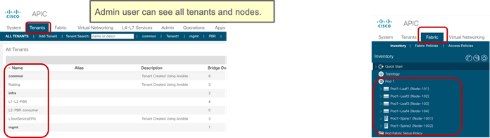
More information can be found at the following link: https://www.cisco.com/c/en/us/td/docs/switches/datacenter/aci/apic/sw/5-x/security/cisco-apic-security-configuration-guide-50x/m-restricted-access-security-domains.html
Virtual Port Channel Hardware Considerations
Cisco ACI provides a routed fabric infrastructure with the capability to perform equal-cost multipathing for Layer 2 and Layer 3 traffic.
In addition, Cisco ACI supports the virtual port channel (vPC) technology on leaf switch ports to optimize server connectivity to the fabric. The purpose of this section is not to describe vPC in detail, but to highlight the relevant considerations for the planning of the physical topology. For more information about vPC, refer to the "Designing the fabric access / Port Channels and Virtual Port Channels" section.
It is very common for servers connected to Cisco ACI leaf switches to be connected through a vPC (that is, a port channel on the server side) to increase throughput and resilience. This is true for both physical and virtualized servers.
vPCs can also be used to connect to existing Layer 2 infrastructure or for L3Out connections (vPC plus a Layer 3 switch virtual interface [SVI]).
Hardware Compatibility Between vPC Pairs
You must decide which pairs of leaf switches in the fabric should be configured as part of the same vPC domain, which in the Cisco ACI configuration is called an "explicit vPC protection group."
When creating a vPC domain between two leaf switches, both switches must be of the same switch generation. Switches not of the same generation are not compatible vPC peers. For example, you cannot have a vPC consisting of a N9K-C9372TX and -EX or -FX leaf switches.
● Generation 1 switches are compatible only with other generation 1 switches. These switch models can be identified by the lack of the "EX," "FX, "FX2," "FX3," "GX" or later suffix at the end of the switch name: for example, N9K-9312TX is a generation 1 switch.
● Generation 2 and later switches can be mixed together in a vPC domain. These switch models can be identified by the "EX," "FX, "FX2," "FX3," "GX" or later suffix at the end of the switch name: for example N9K-93108TC-EX, or N9K-9348GC-FXP are generation 2 switches.
Note When using two different models of the same generation, if there is a difference of scale in terms of forwarding tables, buffers, and so on, you should design your fabric according to the minimum common denominator. We recommend that you use two identical models to be part of the same vPC domain.
Even if two leaf switches of different hardware generation are not meant to be vPC peers, the Cisco ACI software is designed to make the migration from one leaf switch to another compatible switch by using a vPC. Assume that the fabric has Cisco Nexus 9372PX leaf switch pairs (called 9372PX-1 and 9372PX-2 in the following example), and they need to be replaced with Cisco Nexus N9K-C93180YC-EX leaf switches (called 93180YC-EX-1 and 93180YC-EX-2).
The insertion of newer leaf switches works as follows:
● When 93180YC-EX-2 replaces 9372PX-2 in a vPC pair, 9372PX-1 can synchronize the endpoints with 93170YC-EX2.
● The vPC member ports on 93180YC-EX-2 stay down.
● If you remove 9372PX-1, the vPC member ports on 93180YC-EX-2 go up after 10 to 20s.
● 93180YC-EX-1 then replaces 9372PX-1, and 93180YC-EX-2 synchronizes the endpoints with 93180YC-EX-1.
● The vPC member ports on both 93180YC-EX-1 and 93180YC-EX-2 go up.
Members of a vPC must be configured with the same scale profile, however if you need to modify the scale profile on a vPC pair you may need to have two different scale profiles for a transient period required to change the configuration on both.
If you need to modify the scale profile on vPC leaf switches proceed as follows:
● On APIC, configure/enable the new scale profile on a vPC pair. The configuration is pushed to both vPC peers.
● Reload one vPC member at a time (to bring-up the leaf switch with the new profile). During the downtime the other member acts as an active switch.
● Reload the second member vPC leaf switch.
For more information, see the following document:
When configuring vPC pairs, they must be running the same software version. This means that configuration changes should not be performed with different versions, but traffic forwarding for existing configurations still works even with different software versions.
Note: ACI supports certain operations with mixed software versions, but two leaf switches that are part of the same vPC must run the same software release. For more information, see the following document:
With Cisco ACI, you can configure a total of 32 ports as part of the same vPC port channel, with 16 ports on each leaf switch. This capability was introduced in Cisco ACI 3.2. Previously, you could have a total of 16 ports in the vPC with 8 ports per leaf switch.
A FEX can be connected to Cisco ACI with what is known as a straight-through topology, and vPCs can be configured between hosts and FEX.
Different from NX-OS, a FEX cannot be connected to Cisco ACI leaf switches using a vPC.
Placement of Outside Connectivity
The external routed connection, also known as an L3Out, is the Cisco ACI building block that defines the way that the fabric connects to the external world. This can be the point of connectivity of the fabric to a campus core, to the WAN, to the MPLS-VPN cloud, and so on. This topic is extensively covered in the "Designing external layer 3 connectivity" section. The purpose of this section is to highlight physical level design choices related to the external routing technology that you plan to deploy.
Border Leaf Switches with VRF-lite, SR/MPLS Handoff and GOLF
Layer 3 connectivity to the outside can be implemented in one of two ways: by attaching routers to leaf switches (normally designated as border leaf switches) or directly to spine switches. Connectivity using border leaf switches can be further categorized in VRF-lite connectivity and SR/MPLS handoff.
● Connectivity through border leaf switches using VRF-lite: This type of connectivity can be established with any routing-capable device that supports static routing, OSPF, Enhanced Interior Gateway Routing Protocol (EIGRP), or Border Gateway Protocol (BGP), as shown in Figure 5.Figure 5 Leaf switch interfaces connecting to the external router are configured as Layer 3 routed interfaces, subinterfaces, or SVIs.
● Connectivity through border leaf switches using SR/MPLS handoff: This type of connectivity requires -FX or later type of leaf switches (it doesn’t work with first generation leaf switches nor with -EX leaf switches). The router attached to the border leaf switch must be BGP-LU and MP-BGP EVPN-capable. For more information about the SR/MPLS handoff solution, refer to the following document: https://www.cisco.comc/en/us/solutions/collateral/data-center-virtualization/application-centric-infrastructure/white-paper-c11-744107.html#SRMPLSlabelexchangeandpacketwalk
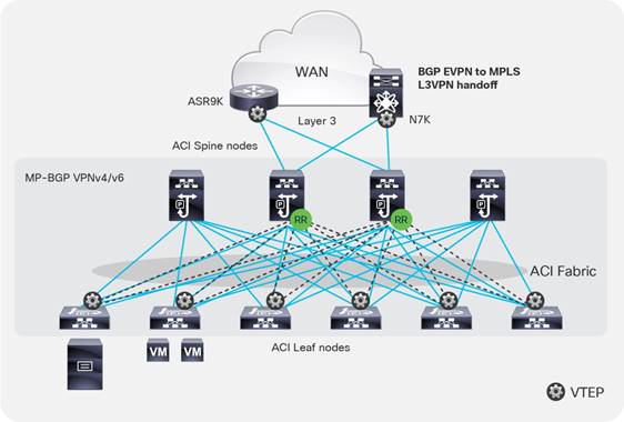
● Connectivity through spine ports with multiprotocol BGP (MP-BGP) EVPN and VXLAN (also known as GOLF): This connectivity option requires that the WAN device that communicates with the spine switches is MP-BGP EVPN-capable and that it optionally supports the OpFlex protocol. This feature uses VXLAN to send traffic to the spine ports as illustrated in Figure 6.Figure 6 This topology is possible only with Cisco Nexus 7000 series and 7700 platform (F3) switches, Cisco® ASR 9000 series Aggregation Services Routers, or Cisco ASR 1000 series Aggregation Services Routers. In this topology, there is no need for direct connectivity between the WAN router and the spine switch. For example, there could be an OSPF-based network in between.
The topology in Figure 5 illustrates the use of border leaf switches to connect to the outside.
The topology in Figure 6 illustrates the connectivity for a GOLF L3Out solution. This requires that the WAN routers support MP-BGP EVPN, OpFlex protocol, and VXLAN. With the topology in Figure 6, the fabric infrastructure is extended to the WAN router, which effectively becomes the equivalent of a border leaf switch in the fabric.
For designs based on the use of a border leaf switch, you can either dedicate leaf switches to border leaf switch functions or use a leaf switch as both a border switch and a computing switch. Using a dedicated border leaf switch is usually considered beneficial, compared to using a leaf switch for both computing and L3Out purposes, for scalability reasons.
For more details about L3Outs based on VRF-lite, or border leaf switches with SR/MPLS handoff or GOLF, refer to the "Designing external layer 3 connectivity" section.
Using Border Leaf Switches for Server Attachment
Attachment of endpoints to border leaf switches is fully supported when all leaf switches in the Cisco ACI fabric are second generation leaf switches or later, such as the Cisco Nexus 9300-EX and Cisco 9300-FX platform switches.
If the topology contains first-generation leaf switches, and regardless of whether the border leaf switch is a first- or second-generation leaf switch, you need to consider the following options:
● If VRF ingress policy is enabled (which is the default configuration), you need to make sure that the software is Cisco ACI release 2.2(2e) or later.
● If you deploy a topology that connects to the outside through border leaf switches that are also used as computing leaf switches, you should disable remote endpoint learning on the border leaf switches.
The recommendation at the time of this writing is that starting with Cisco ACI 3.2 and with topologies that include only -EX leaf switches and newer you don’t need to disable remote endpoint learning.
The "When and How to disable Remote Endpoint Learning" section provides additional information.
Limit the use of L3Out for Server Connectivity
Border leaf switches can be configured with three types of interfaces to connect to an external router:
● Layer 3 (routed) interface
● Subinterface with IEEE 802.1Q tagging
● Switch Virtual Interface (SVI)
When configuring an SVI on an interface of a L3Out, you specify a VLAN encapsulation. Specifying the same VLAN encapsulation on multiple border leaf switches on the same L3Out results in the configuration of an external bridge domain.
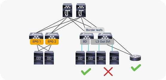
The L3out is meant to attach routing devices including servers that run dynamic routing protocols. It is not meant to attach server interfaces that send Layer 2 traffic directly on the SVI of an L3Out. Sometimes it necessary to use L3Out for server connectivity, when servers run dynamic routing protocols, but except for this scenario, servers should be attached to EPGs and bridge domains.
There are multiple reasons for this:
● The Layer 2 domain created by an L3Out with SVIs is not equivalent to a regular bridge domain.
● The traffic classification into external EPGs is designed for hosts multiple hops away.
You can configure static or dynamic routing protocol peering over a vPC for an L3Out without any special design considerations.
Service Leaf Switch Considerations
When attaching firewalls, load balancers, or other Layer 4 to Layer 7 devices to the Cisco ACI fabric, you have the choice of whether to dedicate a leaf switch or leaf switch pair to aggregate all service devices, or to connect firewalls and load balancers to the same leaf switches that are used to connect servers.
This is a consideration of scale. For large data centers, it may make sense to have leaf switches dedicated to the connection of Layer 4 to Layer 7 services.
For deployment of service graphs with the service redirect feature, dedicated service leaf switches must be used if the leaf switches are first-generation Cisco ACI leaf switches. With Cisco Nexus 9300-EX and newer switches, you do not have to use dedicated leaf switches for the Layer 4 to Layer 7 service devices for the service graph redirect feature.
Cisco ACI has several types of SPAN as the following ones:
● Access SPAN
o Source: access port, port channel (downlink) on a leaf switch
o Destination: local leaf switch interface or an endpoint IP address anywhere in the fabric (ERSPAN)
● Fabric SPAN
o Source: fabric port (fabric link) on a leaf or spine switch
o Destination: an endpoint IP address anywhere in the fabric (ERSPAN)
● Tenant SPAN
o Source: EPGs anywhere in the fabric
o Destination: an endpoint IP address anywhere in the fabric (ERSPAN)
In case of ERSPAN, your SPAN destination can be connected as an endpoint anywhere in the Cisco ACI fabric, which gives more flexibility about where to attach the traffic analyzer (SPAN destination), but it uses bandwidth from the fabric uplinks.
Starting with ACI 4.1 you can use a port channel as a SPAN destination on ACI -EX leaf switches or newer.
Thus, if you need to monitor traffic wherever it’s connected to the Cisco ACI fabric, you might want to consider having a SPAN destination (analyzer) on every single leaf switch. Starting with Cisco ACI 4.2(3), the number of span sessions has increased to 63, which means that you can potentially configure local access span for all front panel ports of a Cisco ACI leaf switch.
In-band and out-of-band Management Connectivity
An administrator can connect to the Cisco APICs, leaf and spine switches of a Cisco ACI fabric using in-band or out-of-band connectivity for management purposes.
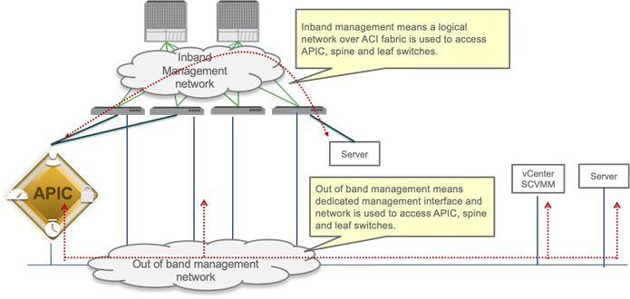
Out-of-band management is mandatory for the Cisco APIC initial setup and requires additional cabling on the management interfaces on the leaf and spine switches (interface mgmt0), whereas in-band management doesn’t require additional cabling as the traffic traverses Cisco ACI fabric.
In-band management is necessary if you plan to use Cisco Nexus Insights: it must be configured on each leaf and spine switch to export telemetry data.
Note: For more information about telemetry, refer to the Cisco Nexus Insight documentation:
https://www.cisco.com/c/en/us/products/data-center-analytics/nexus-insights/index.html
However, an administrator might not be able to connect to leaf and spine switches using an in-band management network if there is something wrong with the Cisco ACI fabric. Thus, the general recommendation is to use out-of-band management or use both in-band and out-of-band managements for critical network connectivity.
If both in-band and out-of-band managements are available, Cisco APIC uses the following forwarding logic:
● Packets that come in an interface go out from the same interface
● Packets sourced from the Cisco APIC, destined to a directly-connected network, go out the directly-connected interface
● Packets sourced from the Cisco APIC, destined to a remote network, prefer in-band, followed by out-of-band by default.
The third bullet needs attention if you have communication sourced from the Cisco APIC, such as VMM domain integration, external logging, export, or import configuration. The preference can be changed at System > System Settings > APIC Connectivity Preferences. Another option is to configure static route on the Cisco APIC, which is available starting from Cisco ACI release 5.1.
For more information about in-band and out-of-band management, refer to the "Fabric Infrastructure (Underlay) / In-Band and Out-of-Band Management" section.
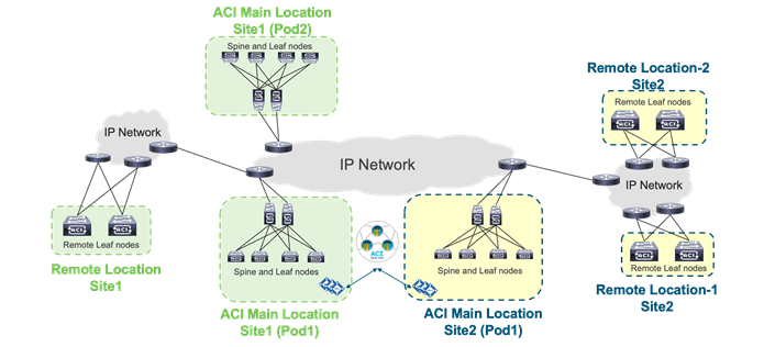
Multiple Locations Data Centers Design Considerations
When having multiple data centers that need to be interconnected with each other, you have the choice of whether to manage network in each location separately, or take advantage of the "Cisco ACI Anywhere" solution that includes Cisco ACI Multi-Pod, Cisco ACI Multi-Site, Remote Leaf, vPod and public cloud integrations.
A detailed description of Cisco ACI Anywhere is outside of the scope of this document, but it is important to keep into account the high-level requirements for extending Cisco ACI when designing and setting up the fabric such as IP addressing used in the infrastructure (TEP pool), Round Trip Time requirements, requirement for Multicast Routing (or not), MTU requirements and so on.
The following solutions are the deployment options to extend multiple on-premises data centers and centrally manage separate physical Cisco ACI fabrics:
● Cisco ACI Multi-Pod: Enables a single Cisco APIC cluster to manage the different Cisco ACI fabrics that are interconnected over a private IP network that must be configured for PIM bidir. Those separate Cisco ACI fabrics are named "pods", and each pod is a regular two-tier or three-tier topology. The same Cisco APIC cluster can manage multiple pods. The main advantage of the Cisco ACI Multi-Pod design is operational simplicity, with multiple separate pods managed as if they were logically a single entity.
● Cisco ACI Multi-Site: Addresses the need for fault domain isolation across different Cisco ACI fabrics that are interconnected over an IP network, which may as well be a WAN without the need for multicast routing in the IP network. Those separate Cisco ACI fabrics are named "Sites", and each site is a regular two-tier or three-tier topology with independent Cisco APIC clusters. Separate Cisco ACI sites are managed by a Cisco ACI Multi-Site Orchestrator (MSO) that provides centralized policy definition and management.
● Remote Leaf Switch: Addresses the need to extend connectivity and consistent policies to remote locations that are connected using a private or a public network (such as a WAN) where it’s not possible or desirable to deploy a full Cisco ACI pod (with leaf and spine switches). The Cisco APIC cluster in the main location can manage the remote leaf switches connected over an IP network as if they were local leaf switches.
Figure 9 provides an example of how to physically connect spine switches and remote leaf switches to the IP network between locations. All of these solutions can be deployed together. The spine and remote leaf switch interfaces are connected to the IP network devices through point-to-point routed interfaces with an 802.1q VLAN 4 value.
The hardware and software requirements are as follows:
● Cisco ACI Multi-Pod requires Cisco ACI 2.0 or later.
● Cisco ACI Multi-Site requires Cisco ACI 3.0 or later, and a second-generation spine switch or later in each site.
● Remote leaf switch requires Cisco ACI 3.1 or later, a second-generation spine switch or later in the main location, and a second-generation leaf switch or later in the remote location.
● First-generation spine switches and second-generation spine switches can be part of the same Cisco ACI fabric. However, only second-generation spine switches should connect to the IP network for Cisco ACI Multi-Site and the remote leaf switch.
● Use of Cisco ACI Multi-Site and a remote leaf switch requires Cisco ACI 4.1(2) or later.
The following design requirements/considerations apply to the IP network between locations:
● MTU (this topic is covered also in the Fabric Infrastructure (undelay) design):
o MTU of the frames generated by the endpoints connected to the fabric: VXLAN encapsulation overhead needs to be taken into consideration. VXLAN data-plane traffic adds 50 bytes of overhead (54 bytes if the IEEE 802.1q header of the original frame is preserved), so you must be sure that all the Layer 3 interfaces in the IP network between locations can accept packets with the increased MTU size. A generic recommendation is to add at least 100 bytes to the MTU configuration on network interfaces for the case where CloudSec encryption is also enabled. For example, if the endpoints are configured with the default 1500-byte value, then the IP network MTU size should be set to 1600 bytes.
o MTU of the MP-BGP control-plane communication between locations: By default, the spine switches generate 9000-byte packets for exchanging endpoint routing information. If that default value is not modified, the IP network between locations must support an MTU size of at least 9000 bytes, otherwise the exchange of control plane information across sites would not succeed (despite being able to establish MP-BGP adjacencies). The default value can be tuned by modifying the corresponding system settings at System > System Settings > Control Plane MTU.
● OSPFv2 is required on external routers that are connected to the spine switch or to a remote leaf switch.
● PIM-Bidir is required for Cisco ACI Multi-Pod.
● DHCP relay is required for Cisco ACI Multi-Pod and a remote leaf switch.
● Ensure that the maximum latency between pods is within the validated limits.
● We recommend that you configure a proper CoS-to-DSCP mapping on Cisco APIC to ensure that traffic received on the destination spine switch or remote leaf switch in a remote location can be assigned to its proper Class of Service (CoS) based on the DSCP value in the outer IP leader of inter-pod VXLAN traffic. This is because the IP network devices between locations are external to the Cisco ACI fabric and may not be possible to assume that the 802.1p values are properly preserved across the IP network and that the DSCP values set by the spine switches before sending the traffic into the IP network can then be used to differentiate and prioritize the different types of traffic. For more information about Cisco ACI QoS, refer to the "Quality of Service (QoS) in ACI" section.
● TEP pool addresses (this topic is covered also in the Fabric Infrastructure (underlay) design):
o Cisco ACI Multi-Pod: Each pod is assigned a separate and non-overlapping infra TEP pool prefix that needs to be routable in the IPN (Interpod Network).
o Cisco ACI Multi-Site: The infra TEP pool prefixes used within each site do not need to be exchanged across sites to allow intersite communication. Instead, the following TEP addresses (which are not from the infra TEP pool): BGP-EVPN Router-ID (EVPN-RID), Overlay Unicast TEP (O-UTEP), and Overlay Multicast TEP (O-MTEP) need to be routable across the Inter-Site Network (ISN) connecting the fabrics. If sites are connected over a WAN, they need to be public routable IP addresses.
o Remote Leaf: Each remote leaf switch location is assigned a remote leaf switch TEP pool that needs to be reachable from all the pods and other remote leaf switches within the same Cisco ACI fabric. Since a Cisco ACI pod could make use of an infra TEP pool that may not be routable across the network infrastructure connecting to the remote leaf switches, you must assign an additional external TEP pool to each Cisco ACI pod part of the fabric. Cisco APICs, spine switches and border leaf switches are automatically allocated TEP IP addresses from these external TEP pools. Due to the fact that the infra TEP pool is meant to be a private network, we strongly recommend that you always configure an external TEP pool.
For more information about each architecture, refer to the white papers:
Fabric Infrastructure (Underlay) Design
The purpose of this section is to describe the initial design choices for the setting up the fabric infrastructure or underlay: the choice of infra VLAN, TEP pool, MP-BGP configuration, hardware profile for the leaf switches, and so on.
This not a replacement to the Cisco APIC Getting Started Guide, which you should consult prior to deploying Cisco ACI:
Choosing the Leaf Switch Forwarding Profile
The hardware of -EX, -FX, FX2, -GX leaf switches or later is based on a programmable hardware architecture. The hardware is made of multipurpose "tiles" where each tile can be used to perform routing functions or filtering functions and so on. Starting with the Cisco ACI 3.0 release, the administrator can choose to which function to allocate more tiles based on predefined profiles.
Note The profile functionality is available on the -EX, -FX, -FX2, and -GX leaf switches, but not on the Nexus 9358GY-FXP switch.
The functions whose scale is configurable using the use of tiles are:
● The MAC address table scalability
● The IPv4 scalability
● The IPv6 scalability
● The Longest Prefix Match table scalability
● The Policy Cam scalability (for contracts/filtering)
● The space for Routed Multicast entries
The default profile (called also "Dual Stack") allocates the hardware as follows:
● MAC address table scalability: 24k entries
● The IPv4 scalability: 24k entries
● The IPv6 scalability: 12k entries
● The Longest Prefix Match table scalability: 20k entries
● The Policy Cam scalability (for contracts/filtering): 64k entries
● Multicast: 8k entries
Table 1 provides the information about the scale of different profiles and in which release they were introduced. The rows in the table that do not specify the type of leaf switch are applicable to -EX, -FX, -FX2, and -GX leaf switches.
| Tile profile |
Cisco ACI Release when first introduced |
EP MAC
|
EP IPv4 |
EP IPv6 |
LPM |
Policy |
Multicast |
| Default |
Release 3.0 |
24K |
24K |
12K |
20K (IPv4) 10k (IPv6) |
61K (Cisco ACI 3.0) 64K (Cisco ACI 3.2) |
8K (Cisco ACI 3.0) |
| IPv4 |
Release 3.0 |
48K |
48K |
0 |
38K (IPv4) 0 (IPv6) |
61K (Cisco ACI 3.0) 64K (Cisco ACI 3.2) |
8K (Cisco ACI 3.0)) |
| High Dual Stack for -EX, -FX2 |
Release 3.1 |
64k |
64k |
24K |
38K (IPv4) 19K (IPv6) |
8k (Cisco ACI 3.1) |
0 (in Cisco ACI 3.1) 512 (in Cisco ACI 3.2) |
| High Dual Stack for -FX, -GX |
Release 3.1 (FX only) |
64K |
64K |
24K (ACI3.1) 48K (Cisco ACI 3.2) |
38K (IPv4) 19K (IPv6) |
8k (Cisco ACI 3.1) 128K (Cisco ACI 3.2) |
0 (in Cisco ACI 3.1) 512 (in Cisco ACI 3.2) 32k (in Cisco ACI 4.0) |
| High LPM |
Release 3.2 |
24K |
24K |
12K |
128k (IPv4) 64k (IPv6) |
8K |
8K |
| High Policy (N9K-C93180YC-FX and N9K-C93600CD-GX with 32GB of RAM only) |
Release 4.2 |
24K |
24K |
12K |
20K (IPv4) 10k (IPv6) |
256K |
8K |
Note: Cisco Nexus 9300-FX2 with the High Dual Stack profile cannot compress policy-cam rules.
When deploying the fabric, you may want to define from the very beginning which forwarding profile is more suitable for the requirements of your data center.
The default profile configures the leaf switch for support of both IPv4 and IPv6 and Layer 3 multicast capacity. But, if you plan to use Cisco ACI primarily as a Layer 2 infrastructure, the IPv4 profile with more MAC address entries and no IPv6 entries may be more suitable. If, instead, you plan on using IPv6, the high dual-stack profile may be more suitable for you. Some profiles offer more capacity for the Longest Prefix Match table for designs where, for instance, Cisco ACI is a transit routing network, in which case the fabric offers less capacity for IPv4 and IPv6.
The profile configuration is done per leaf switch, so you can potentially define different scale profiles for leaf switches that are used for different purposes. For example, you may want to configure a leaf switch that is used as a dedicated border leaf switch with a bigger Longest Prefix Match table.
The configuration of the hardware profiles can be performed from Fabric > Access > Leaf Switches > Policy-Groups > Forwarding Scale Profile Policy as illustrated in the following picture:

Note You need to reboot the leaf switch after changing the hardware profile.
There is also the possibility to set the forwarding scale profile from the capacity dashboard. You should use this second approach with caution, because when you modify the leaf switch profile from the capacity dashboard, the UI selects the profile that is already associated with the leaf switch that you chose. Normally the profile that is associated with all leaf switches is the "default" profile. Hence, if you modify a profile, you will modify the hardware profile for all the leaf switches. To prevent this operational mistake, you should configure a non-default policy group for all the leaf switches or per group of leaf switches that share the same use/characteristics.
For more information about the configurable forwarding profiles, see the following document:
When configuring a Cisco ACI fabric, you need to give a fabric-id to it. The fabric-id should not be confused with the pod-id or the site-id. You should just use "fabric-id 1," unless there is some specific reason not to, such as if you plan to use GOLF with Auto-RT, and all sites belong to the same ASN. Refer to the Cisco ACI Multi-Site Architecture white paper for more information:
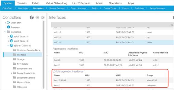
The Cisco APIC communicates with the Cisco ACI fabric through a VLAN that is associated with the tenant called infrastructure, which appears in the Cisco APIC User Interface as tenant "infra". This VLAN is used for internal control communication between fabric switches (leaf and spine switches and Cisco APICs).
The infrastructure VLAN number is chosen at the time of fabric provisioning. This VLAN is used for internal connectivity between the Cisco APIC and the leaf switches.
From the GUI, you can see which infrastructure VLAN is in use, as in Figure 11. From the command-line interface, you can find the infrastructure VLAN; for instance, by using this command on a leaf switch:
leaf1# show system internal epm vlan all | grep Infra
The infrastructure VLAN is also used to extend the Cisco ACI fabric to another device. For example, when using Cisco ACI with Virtual Machine Manager (VMM) integration, the infrastructure VLAN can be used by Cisco ACI Virtual Edge to send DHCP requests and get an address dynamically from the Cisco ACI fabric TEP pool and to send VXLAN traffic.
In a scenario in which the infrastructure VLAN is extended beyond the Cisco ACI fabric (for example, when using Cisco ACI Virtual Edge, OpenStack integration with OpFlex protocol, or Hyper-V integration), this VLAN may need to traverse other (that is, not Cisco ACI) devices.
Note: To enable the transport of the infrastructure VLAN on Cisco ACI leaf switch ports, you just need to select the checkbox in the Attachable Access Entity Profile (AAEP) that is going to be associated with a given set of ports.
Common Reserved VLANs on External Devices
Some platforms (for example, Cisco Nexus 9000, 7000, and 5000 series switches) reserve a range of VLAN IDs, typically 3968 to 4095.
In Cisco UCS, the VLANs that can be reserved are the following:
● FI-6200/FI-6332/FI-6332-16UP/FI-6324: 4030–4047. Note that vlan 4048 is being used by VSAN 1.
● FI-6454: 4030-4047 (fixed), 3915–4042 (can be moved to a different 128 contiguous block VLAN, but requires a reboot).
To avoid conflicts, we highly recommend that you choose an infrastructure VLAN that does not fall within the reserved range of other platforms. For example, choose a VLAN < 3915.
Hardening the Infrastructure VLAN
Starting with Cisco ACI 5.0 it is possible to harden the infrastructure VLAN to limit the traffic that is allowed on the infra VLAN from the front panel ports by restricting it to the traffic generated by the Cisco APICs, or OpFlex or VXLAN-encapsulated traffic generated by hypervisors.
You can configure Cisco ACI for this from System Settings > Fabric-Wide Settings > Restrict Infra VLAN Traffic.
Cisco ACI forwarding is based on a VXLAN overlay. Leaf switches are virtual tunnel endpoints (VTEPs), which, in Cisco ACI terminology, are known as PTEPs (physical tunnel endpoints).
Cisco ACI maintains an endpoint database containing information about where (that is, on which TEP) an endpoint's MAC and IP addresses reside.
Cisco ACI can perform Layer 2 or Layer 3 forwarding on the overlay. Layer 2 switched traffic carries a VXLAN network identifier (VNID) to identify bridge domains, whereas Layer 3 (routed) traffic carries a VNID with a number to identify the VRF.
Cisco ACI uses a dedicated VRF and a subinterface of the uplinks as the infrastructure to carry VXLAN traffic. In Cisco ACI terminology, the transport infrastructure for VXLAN traffic is known as Overlay-1, which exists as part of the tenant "infra".
The Overlay-1 VRF contains /32 routes to each VTEP, vPC virtual IP address, Cisco APIC, and spine-proxy IP address.
The VTEPs representing the leaf and spine switches in Cisco ACI are called physical tunnel endpoints, or PTEPs. In addition to their individual PTEP addresses, spine switches can be addressed by a proxy TEP. This is an anycast IP address that exists across all spine switches and is used for forwarding lookups. Each VTEP address exists as a loopback on the Overlay-1 VRF.
vPC loopback VTEP addresses are the IP addresses that are used when leaf switches forward traffic to and from a vPC port.
The fabric is also represented by a fabric loopback TEP (FTEP), used to encapsulate traffic in VXLAN to a vSwitch VTEP if present. Cisco ACI defines a unique FTEP address that is identical on all leaf switches to allow mobility of downstream VTEP devices.
All these TEP IP addresses are assigned by the Cisco APIC to leaf and spine switches using DHCP addressing. The pool of these IP addresses is called TEP pool, and it is configured by the administrator at the fabric initial setup.
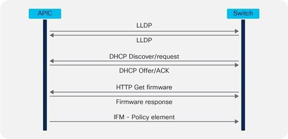
The Cisco ACI fabric is brought up in a cascading manner, starting with the leaf switches that are directly attached to the Cisco APIC. Link Layer Discover Protocol (LLDP) and control-plane IS-IS protocol convergence occurs in parallel to this boot process. The Cisco ACI fabric uses LLDP-based and DHCP-based fabric discovery to automatically discover the fabric switch switches, assign the infrastructure TEP addresses, and install the firmware on the switches.
Figure 12 shows how bootup and autoprovisioning works for the Cisco ACI switches. The switch gets an IP address from the Cisco APIC. Then, the switch asks to download the firmware through an HTTP GET request.
Although TEPs are located inside the fabric, there are some scenarios where the TEP range may be extended beyond the fabric. As an example, when you use Cisco ACI Virtual Edge, fabric TEP addresses are allocated to the virtual switch. Therefore, it is not advisable to use overlapping addresses between the internal TEP range and the external network in your data center. Furthermore, when planning for the TEP pool you, should also keep into account the requirements of Cisco ACI Multi-Pod or Cisco ACI Multi-Site and so on if you plan to deploy a Cisco ACI in multiple data centers as described in the "Multiple locations Data Centers design considerations" section.
It is important to distinguish the following types of TEP pools:
● The infra TEP pool: This is the pool of IP addresses used for the loopbacks on spine switches, leaf switches, vPCs, and so on, and the pool is typically just a private IP address space, which may need to be routable on a private network (for instance on an IPN for Cisco ACI Multi-Pod), but doesn’t need to be externally routable on a WAN. The infra TEP pool is defined at provisioning time (day 0).
● The remote TEP pool: This is a pool to provide addressing for remote leaf switches that you don’t need to configure at the fabric bring up time. The pool has to be a routable pool of IP addresses and not just a private pool, as it is possibly used over a WAN. This pool is configured when and if there is a need to connect remote leaf switches. The configuration can be found at: Fabric > Inventory > Pod Fabric Setup Policy > Physical Pods > Remote Pools.
● The external TEP pool: This is a pool that doesn’t need to be configured at the fabric bring up. The purpose of this pool is to provide externally routable IP addresses for the Cisco APICs, spine switches, and border leaf switches for scenarios where some TEP addresses need to be routable over a public network. Examples are the use of remote leaf switches and the Inter-Site L3Out. This feature has been added from Cisco ACI 4.1(2). The configuration can be found at: Fabric > Inventory > Pod Fabric Setup Policy > Physical Pods > External TEP. The external TEP pool feature gives more freedom in the design of the IP network (to connect to remote leaf switches for instance) in that you don’t need to plan to carry infra TEP addresses on it, instead Cisco ACI uses the external TEP pool addresses for traffic that needs to be sent over the WAN. You can find more information in the following document:
● Other External TEP addresses: You need addresses such as the Control-Plane External Tunnel Endpoint, the Data-Plane ETEP, the Head-End Replication ETEP when and if deploying Cisco ACI Multi-Site. The addresses can be external, public routable IP addresses that are not from the infra TEP pool nor from the external TEP pool. You can configure the addresses using the Cisco ACI Multi-Site Orchestrator.
For the purpose of this design guide, the focus is on the infra TEP pool.
The number of addresses required for the infra TEP address pool depends on a number of factors, including the following:
● Number of Cisco APICs
● Number of leaf and spine switches
● Number of Cisco ACI Virtual Edge instances, Hyper-V hosts or, more generally, virtualized hosts managed using VMM integration and integrated with OpFlex
● Number of vPCs required
Note: In this calculation, you do not need to include the count of switches of a different pod because each pod uses its own TEP pool that should not overlap with other pod pools, as described in the following document:
To avoid issues with address exhaustion in the future, we strongly recommend that you allocate a /16 or /17 range, if possible. If this is not possible, a /19 range should be considered the absolute minimum. However, this may not be sufficient for larger deployments. It is critical for you to size the TEP range appropriately, because you cannot easily modify the size later.
You can verify the TEP pool after the initial configuration by using the following command:
Apic1# moquery –c dhcpPool
If you are planning to use Cisco ACI Multi-Pod, Cisco ACI Multi-Site, a remote leaf switch, and vPod in the future, the following list summarizes the TEP address-related points:
● Cisco ACI Multi-Pod: You need to make sure the pool you define is nonoverlapping with other existing or future pods. However, to count the infra TEP pool range, you do not need to include the count of switches of a pod other than the one you are configuring, because each pod uses its own infra TEP pool that should not overlap with other pod pools, as described in the following document:
● Cisco ACI Multi-Site: With Cisco ACI Multi-Site, each site uses an independent TEP pool, so you could potentially re-use the same infra TEP pool as another site. Quoting https://www.cisco.com/c/en/us/solutions/collateral/data-center-virtualization/application-centric-infrastructure/white-paper-c11-739609.pdf: "The TEP pool prefixes used within each site do not need to be exchanged across sites to allow intersite communication. As a consequence, there are no technical restrictions regarding how those pools should be assigned. However, the strong recommendation is not to assign overlapping TEP pools across separate sites so that your system is prepared for future functions that may require the exchange of TEP pool summary prefixes."
● Cisco ACI Multi-Site uses these public routable TEP addresses in addition to the infra TEP pool: The Control-Plane External Tunnel Endpoint (one per spine connected to the Inter-Site Network), the Data-Plane ETEP (one per site per pod) and the Head-End Replication ETEP (one per site).
● The support for Intersite L3Out mandates the deployment of an "external TEP pool" for each site that is part of the Cisco ACI Multi-Site domain. These addresses are added to the border leaf switch infra TEP address. For more information, refer to the following document:
● For remote leaf switches, you need to consider the need to configure a routable TEP pool for the Cisco APICs, spine switches, and border leaf switches, but starting from Cisco ACI 4.1(2) you can use the external TEP pool feature instead. You can find more information in the following document:
Note You can view the infra TEP pool as well as the external TEP pools from Fabric > Inventory > Pod Fabric Setup Policy.
In the bring up phase, you need to provide a multicast range that Cisco ACI uses as an external multicast destination for traffic in a bridge domain. This address can be any address in the range 225.0.0.0/15 to 231.254.0.0/15, and it should be a /15. This address range is needed for Cisco ACI to forward multidestination traffic on bridge domains because Cisco ACI implements routed multicast trees in the underlay for this type of traffic.
Each bridge domain is assigned a group IP outer (GIPo) address (as opposed to group IP inner [GIPi] or the multicast address in the overlay). This is also referred to as the flood GIPo for the bridge domain and is used for all multidestination traffic on the bridge domain inside the fabric. The multicast tree in the underlay is set up automatically without any user configuration. The roots of the trees are always the spine switches, and traffic can be distributed along multiple trees according to a tag, known as the forwarding tag ID (FTAG).
With Cisco ACI Multi-Pod, the scope of this multicast address range encompasses all pods, hence multicast routing must be configured on the Inter-Pod Network.
Routing in the infrastructure VRF is based on IS-IS. Routing within each tenant VRF is based on host routing for endpoints that are directly connected to the Cisco ACI fabric, or Longest Prefix Match (LPM) with bridge domain subnets or routes from external routers learned from a border leaf switch. A border leaf switch is where Layer 3 Outs (L3Outs) are deployed.
Cisco ACI uses MP-BGP VPNv4/VPNv6 to propagate external routes in tenant VRF instances within a pod.
In the case of Cisco ACI Multi-Pod and Cisco ACI Multi-Site, Cisco ACI uses MP-BGP VPNv4/VPNv6/EVPN to propagate endpoint IP/MAC addresses and external routes in tenant VRF instances between pods or sites.
Cisco ACI uses BGP route reflectors to optimize the number of BGP peers.
There are two types of route reflectors in Cisco ACI:
● Regular BGP route reflectors are used for VPNv4/VPNv6 within a pod between leaf and spine switches.
● External BGP route reflectors are used for VPNv4/VPNv6/EVPN across pods between spine switches for Cisco ACI Multi-Pod, or sites for Cisco ACI Multi-Site.
The BGP Route Reflector Policy controls which spine switches should operate as BGP reflectors within a pod (regular) and between pods/sites (external).
Regular BGP route reflectors must be configured per pod while external BGP route reflectors are optional.
When using Cisco ACI Multi-Pod or Cisco ACI Multi-Site, if external BGP route reflectors are not configured, spine switches between pods or sites will form a full mesh of iBGP peers.
It is important to note that the BGP Autonomous System (AS) number is a fabric-wide configuration setting that applies across all Cisco ACI pods that are managed by the same Cisco APIC cluster (Cisco ACI Multi-Pod).
To enable and configure MP-BGP within the fabric, you can find the configuration depending on the release as follows:
● Under Fabric > Fabric Policies > Pod Policies > BGP Route Reflector default
● Under System > System Settings > BGP Route Reflector.
The default BGP Route Reflector Policy should then be added to a Pod Policy Group and pod profile to make the policy take effect, as shown in Figure 13.
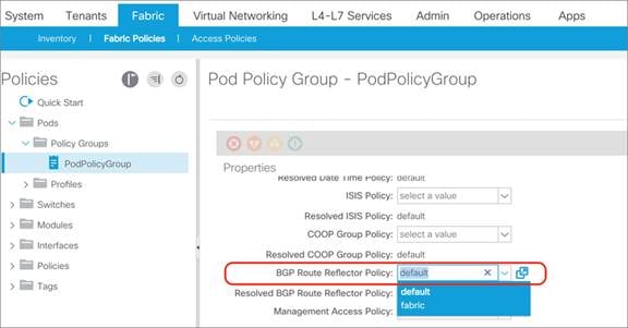
After spine switches are configured as regular BGP route reflectors, all leaf switches in the same pod will establish MP-BGP VPNv4/v6 neighborship with those spine switches through the infra VRF.
After the border leaf switch learns the external routes, it redistributes the external routes within the same tenant VRF first so that the routes are populated in the BGP IPv4/v6 routing table, then exports them to the MP-BGP VPNv4/v6 address family instance in the infra VRF along with their original tenant VRF information.
Within MP-BGP in the infra VRF, the border leaf switch advertises routes to a spine switch, which is a BGP route reflector. The routes are then propagated to all the leaf switches. Then, the leaf switch imports the routes from the VPNv4/v6 table into the respective tenant VRF IPv4/v6 table if the VRF is instantiated on it.
Figure 14 illustrates the routing protocol within the Cisco ACI fabric and the routing protocol between the border leaf switch and external router using VRF-lite.
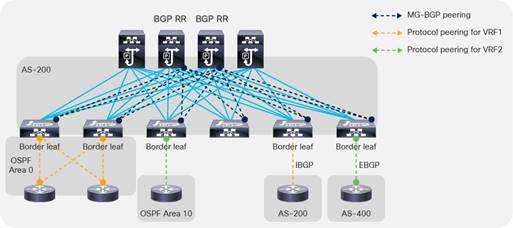
BGP Autonomous System Number Considerations
The Cisco ACI fabric supports one Autonomous System (AS) number. The same AS number is used for internal MP-BGP and for the BGP session between the border leaf switches and external routers. Although you could use the local AS configuration per BGP neighbor so that the external routers can peer using another BGP AS number, the real Cisco ACI BGP AS number still appears in the AS_PATH attribute of BGP routes. Hence, we recommend that you pick a number so that you can design your BGP network with the whole Cisco ACI fabric as one BGP AS.
BGP Route-Reflector Placement Considerations
For regular BGP route reflectors that are used for traditional L3Out connectivity (that is, through leaf switches within each pod), you must configure at least one route reflector per pod. However, we recommend that you configure a pair of route reflectors per pod for redundancy, as shown in Figure 15.
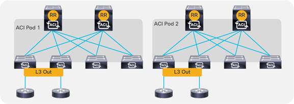
For external BGP route reflectors that are used for Cisco ACI Multi-Pod/Cisco ACI Multi-Site, we generally recommend that you use full mesh BGP peering instead of using external BGP route reflectors for the sake of configuration simplicity. Refer to the following documents for details on Cisco ACI Multi-Pod and Cisco ACI Multi-Site external route reflector deployments:
● Cisco ACI Multi-Pod White Paper
● Cisco ACI Multi-Site Architecture White Paper
As with any other deployment running BGP, it is good practice to limit the number of AS paths that Cisco ACI can accept from a neighbor. This setting can be configured per tenant under Tenant > Networking > Protocol Policies > BGP > BGP Timers by setting the Maximum AS Limit value.
Network Time Protocol (NTP) configuration
As part of the initial configuration of the Cisco ACI fabric you want and need to configure the NTP protocol to synchronize leaf switches, spine switches, and Cisco APIC nodes to a valid time source.
This is done over the out-of-band management network.
Figure 16 illustrates where to configure NTP.
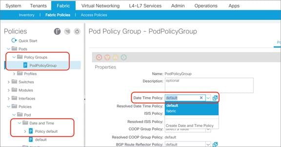
Cisco ACI can also be configured so that the Cisco ACI leaf switches provide the NTP server functionality for the servers attached to the fabric.
For more information about NTP, refer to the following documents:
Cisco ACI also lets you configure the Precision Time Protocol (PTP), but in Cisco ACI, NTP and PTP are used for different purposes. Cisco ACI 3.0 introduced support for the PTP protocol for -EX and newer leaf switches for latency measurements within the fabric. Cisco ACI 4.2(5) and 5.1(1) then introduced support for timing synchronization with external PTP nodes using down links of leaf switches. Support for the PTP Telecom profile with Full Timing Support (ITU-T G.8275.1) was also introduced from Cisco ACI 5.2(1).
The latency measurements features let you measure the latency of the traffic that the Cisco ACI leaf and spine switches are forwarding. Cisco ACI provides two types of measurements:
· Ongoing latency measurements between leaf switches (between PTEPs)
· On-demand latency measurements for troubleshooting (for instance to measure latency between two endpoints).
This use of PTP doesn’t require an external PTP GM clock because the purpose of PTP here is to calculate the time delta between ACI switches for latency measurements, but not to show the accurate time.
To support latency measurements across ACI pods, all pods need to synchronize to the same clock.
For this purpose, it is recommended, but not required, to connect an external PTP GM with primary reference time clock (PRTC) such as GPS/GNSS to the IPN and configure IPN nodes as PTP nodes such that each pod can synchronize to the GM through IPN with almost the same number of hops. If a GM with a Primary Reference Time Clock (PRTC) is not available, one of the IPN nodes or one of the ACI switches can be used as the GM (even if it cannot sync with a PRTC).
This is done by following the Best Master Clock Algorithm (BMCA) which is an algorithm defined in the IEEE 1588 standard for PTP.
By default, ACI switches are configured with PTP “priority1” of 255 (or starting from 4.2(5) to a user configurable value) except for one spine in each pod which is configured with PTP priority1 set to the value of the other ACI switches minus one, that is 254: this ensures a deterministic assignment of a GM per each pod if the IPN is not configured to forward PTP frames but it is desirable and recommended that all devices in the same fabric synchronize to the same GM.
To make sure that all pods synchronize to the same clock, IPN nodes must be configured as PTP nodes or at least must not block PTP messages from one pod to another.
ACI can also be used for the timing synchronization with external PTP nodes via down links of leaf switches. This allows the use of ACI switches as regular PTP boundary clocks (BC) to provide synchronization to ordinary clocks (OC) on the endpoints. For this use case, an external PTP GM is required.
COOP is used within the Cisco ACI fabric to communicate endpoint information between spine switches. Starting with software release 2.0(1m), the Cisco ACI fabric has the ability to authenticate COOP messages.
The COOP Group Policy (which can be found under System Settings, COOP group or with older releases under Fabric Policies, Pod Policies) controls the authentication of COOP messages. Two modes are available: Compatible Mode and Strict Mode. Compatible Mode accepts both authenticated and non-authenticated connections, provides backward compatibility, and is the default option. Strict Mode allows MD5 authentication connections only. The two options are shown in Figure 17.
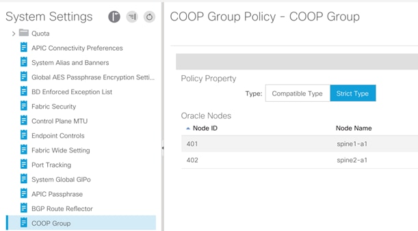
We recommend that you enable Strict Mode in production environments to help ensure the most secure deployment.
In-Band and Out-of-Band Management
Management access to the APICs and the leaf and spine switches of a Cisco ACI fabric can be defined using in-band or out-of-band connectivity. In-band management consists in managing all the Cisco ACI leaf and spine switches from one or more leaf switch ports. The advantage is that you can just connect a couple of ports from one or more leaf switches of your choice, and Cisco ACI routes the management traffic to all the leaf and spine switches in the fabric using the fabric links themselves.
With out-of-band connectivity you can manage Cisco ACI leaf and spine switches using the management port (mgmt0).
Both in-band and out-of-band connectivity configurations in Cisco ACI are performed in the special predefined tenant "mgmt".
In classic NX-OS networks, access control for in-band management is configured using the vty access-lists, whereas the configuration to control access to the out-of-band management is configured using an access-group on the mgmt0 port, as described in the following document:
In Cisco ACI, access control is performed using EPGs and contracts and this is no different for in-band or out-of-band management access, except for the fact that the in-band and out-of-band EPGs are not the regular EPGs, but they are configured as node management EPGs of type In-Band or Out-of-Band and, in the case of out-of-band management, contracts are a different object than regular contracts; they are "Out-of-Band Contracts."
The in-band management addresses are just loopback IP addresses defined in a special tenant called "mgmt" on a predefined bridge domain called "inb" on a predefined VRF called also "inb". These IP addresses belong to the special in-band EPG, which it can be the default one called "default" or a new EPG of type In-Band EPG that you have created. The in-band and out-of-band management addresses are defined from Tenants > mgmt > Node Management Addresses.
This configuration requires entering the switch ID, the IP address for the device that you want to configure, the default gateway, and which EPG (of type In-Band or Out-of-Band) it is associated with. Assuming that you defined the In-Band EPG "default" with VLAN-86 for example, and that you defined as a node management address for node-1 (APIC1) 10.62.104.34/29 and that the default gateway is the inb bridge domain subnet 10.62.104.33, then the configuration on the Cisco APIC would be updated with a subinterface for bond0, in this case for VLAN 86, hence bond0.86:
admin@apic-a1:~> ifconfig -a
bond0.86: flags=4163<UP,BROADCAST,RUNNING,MULTICAST> mtu 1496
inet 10.62.104.34 netmask 255.255.255.248 broadcast 10.62.104.39
admin@apic-a1:~> ip route
default via 10.62.104.33 dev bond0.86 metric 32
Out-of-band management addresses are IP addresses assigned to the mgmt0 interfaces in the special tenant called "mgmt." The IP addresses belong to the special out-of-band EPG (either the "default" or an EPG of type Out-of-Band that you created). Out-of-band contracts are a different object (vzOOBBrCP) from the regular contracts, and can only be provided by the special EPGs, the out-of-band EPGs (mgmtOoB) and can only be consumed by a special "L3 external" the External Management Instance Profile (mgmtInstP).
In-band Connectivity to the Outside
The "inb" bridge domain in principle is meant to connect primarily APICs and Cisco ACI leaf and spine switches. You could theoretically connect management devices to the inb bridge domain, but we do not recommend doing this because Cisco ACI has implicit configurations in place in this bridge domain to enable Cisco APIC to Cisco ACI leaf and spine switch communication.
Also, Cisco ACI spine switches have a requirement such that management traffic to the loopback management interface has to be routed (this is because of hardware reasons), hence we normally recommend that you configure another bridge domain for outside connectivity, or you can use an L3Out.
There are two ways for in-band management to connect to the outside and they can be used simultaneously (they don’t exclude each other):
● Define an "external" bridge domain with an external EPG with a contract to the in-band EPG: If you create a bridge domain, this must belong to the same "inb" VRF, and you would also need to define an EPG to associate the external traffic to this bridge domain. A contact defines which management traffic is allowed between the EPG that you created for outside traffic and the in-band EPG. This configuration is useful if Cisco APIC needs to manage devices directly attached to the Cisco ACI leaf switches (for example, a Virtual Machine Manager device directly attached to the fabric) or if the network management devices are directly attached to the Cisco ACI leaf switches.
● Define an L3Out: This L3out would be associated with the inb VRF and you would need to define a Layer 3 Outside to match the management IP addresses or subnets, and a contract between the Layer 3 Outside and the in-band EPG. This configuration is useful if network management devices are not directly connected to the Cisco ACI leaf switches.
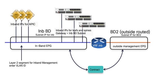
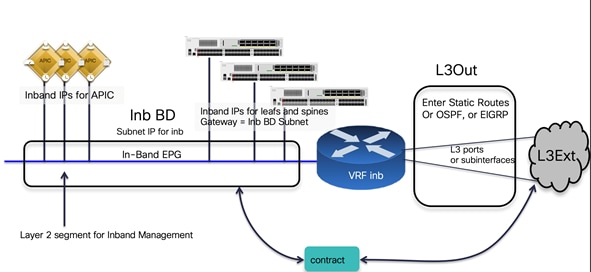
In-band Management Configuration
Assuming that you want to define the same security policy for the Cisco APICs, leaf and spine switches, the configuration for in-band management using an L3Out includes the following steps:
● Assigning a subnet to the in-band bridge domain and using this subnet address as the gateway in the node management address configuration.
● Assigning all the Cisco APICs, leaf switches, and spine switches to the same in-band EPG (for instance the default one). Whether you are using the predefined "default" EPG of type In-Band EPG or you create a new EPG of type In-Band EPG, you need to assign a VLAN to the in-band EPG, which needs to be trunked to the Cisco APIC too. The assignment of Cisco APICs, leaf switches, and spine switches to the in-band EPG is done using the static node management address configuration where you define both the IP address to give to the Cisco ACI node as well as to which in-band EPG it belongs. Alternately, you can perform the assignment using the managed node connectivity groups if you want to just provide a pool of IP addresses that Cisco ACI assigns to the switches.
● Defining the list of which management hosts or subnets can access Cisco APIC, leaf switches, and spine switches. For this you can define a L3Out and an external EPG associated with the VRF inb.
● Defining a contract for in-band management that controls which protocol and ports can be used by the above hosts to connect to the Cisco APIC, leaf switches, and spine switches.
● Providing the in-band contract from the in-band EPG and consuming the contract from the L3Out.
Out-of-band Management Configuration
Assuming that you want to define the same security policy for the Cisco APICs, leaf switches, and spine switches, the configuration of out-of-band management includes the following steps:
● Assigning all the Cisco APICs, leaf switches, and spine switches to the same out-of-band EPG (for instance the default one). This is done using the static node management address configuration where you define both the IP address to give to the Cisco ACI node as well as which out-of-band EPG it belongs to. You can also perform the assignment using the managed node connectivity groups if you want to just provide a pool of IP addresses that Cisco ACI assigns to the switches.
● Defining the list of which management hosts can access Cisco APIC, leaf switches, and spine switches. This is modeled in a way that is similar to an external EPG called the external management instance profile (mgmtInstP)
● Defining the out-of-band contracts (vzOOBBrCP) that control which protocol and ports can be used by the above hosts to connect to the Cisco APIC, leaf switches, and spine switches.
● Providing the out-of-band contract from the out-of-band EPG and consuming the contract from the external management instance profile.
The following picture illustrates the configuration of out-of-band management in tenant mgmt. Notice that the name of the default out-of-band EPG is "default," just as with the name of the default in-band EPG, but these are two different objects and so the names can be identical.
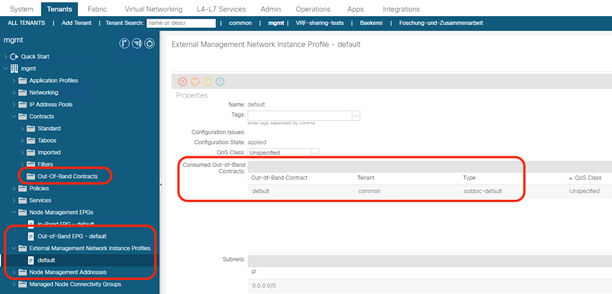
If both in-band and out-of-band managements are available, Cisco APIC uses the following forwarding logic:
● Packets that come in an interface, go out from the same interface. Therefore, if your management station manages Cisco APIC from out-of-band, Cisco APIC keeps using that out-of-band interface to communicate with the management station.
● Packets sourced from the Cisco APIC, destined to a directly connected network, go out the directly connected interface.
● Packets sourced from the Cisco APIC, destined to a remote network, prefer in-band, followed by out-of-band by default. The preference can be changed at System > System Settings > APIC Connectivity Preferences > Interface to use for External Connections.
● Another option is to configure static routes on the Cisco APIC by entering the route in the EPG: Tenant mgmt > Node Management EPGs > In-Band EPG – default or Out-of-Band EPG – default. This option is available starting from Cisco APIC release 5.1.
You can configure routes on the Cisco APIC or on the other leaf and spine switches for the management interfaces from Tenant mgmt > Node Management EPGs > In-Band EPG – default or Out-of-Band EPG – default by configuring static routes as part of this special EPG configuration.
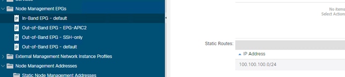
In this example, assigning a static route to the In-Band EPG – default creates the following route on the Cisco APIC:
100.100.100.0/24 via 10.62.104.33 dev bond0.86
Management Connectivity for VMM Integration
If you use a VMM configuration, Cisco APIC must talk to the Virtual Machine Manager API (for instance, the VMware vCenter API).
For this management connectivity, it is a good idea to use a path that has the least number of dependencies on the fabric. Consider for instance if the VMM is reachable using an L3Out and if there are configuration changes on the MP-BGP configuration, this may also affect the Cisco APIC-to-VMM communication path.
Because of this, it can be preferable to use one of the following options for management communication between Cisco APIC and the Virtual Machine Manager:
● An out-of-band network
● A bridge domain associated with the in-band VRF in tenant Management
In-band Management Requirements for Telemetry
The following list highlights some design considerations related to deployment of in-band and out-of-band management:
● In-band management is required for hardware telemetry. For more information, refer to the following document:
● Nexus Dashboard requires in-band connectivity for Network Insight Advisor and Network Insight Resources and out-of-band connectivity for Cisco ACI MSO. If the Nexus Dashboard is directly attached to the Cisco ACI fabric, it can be configured for in-band connectivity using the external EPG/bridge domain approach. If instead the Nexus Dashboard is several hops away from the fabric, it can be configured to access Cisco ACI fabrics using an L3Out in-band configuration.
IS-IS Metric for Redistributed Routes
It is considered a good practice to change the IS-IS metric for redistributed routes to lower than the default value of 63. This is to ensure that when (for example) a spine switch is rebooting because of an upgrade, the switch is not in the path to external destinations until the entire configuration of the spine switch is completed, at which point the metric is set to the lower metric, such as 32.
This configuration can be performed from Fabric/Fabric Policies/Policies/Pod/ISIS Policy default.
Figure 22 shows the format of the VXLAN encapsulated traffic in the Cisco ACI fabric.
An Ethernet frame may arrive at a fabric access port encapsulated with a VLAN header, but the VLAN header is removed so the Ethernet frame size that is encapsulated in the VXLAN payload is typically 1500 for the original MTU size + 14 bytes of headers (the frame-check sequence [FCS] is recalculated and appended, and the IEEE 802.1q header is removed). In addition, the Ethernet frame transported on the fabric wire carries IP headers (20 bytes), UDP headers (8 bytes), and iVXLAN headers (8 bytes).
The VXLAN header used in the Cisco ACI fabric is shown in Figure 22.
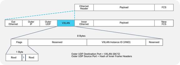
Therefore, the minimum MTU size that the fabric ports need to support is the original MTU + 50 bytes. The Cisco ACI fabric uplinks are configured with the MTU of the incoming packet (which is set by default to 9000 Bytes) + 150 bytes.
The MTU of the fabric access ports is 9000 bytes, to accommodate servers sending jumbo frames.
Note: In contrast to traditional fabrics, which have a default MTU of 1500 bytes, Cisco ACi does not need you to configure jumbo frames manually, because the MTU is already set to 9000 bytes.
You normally do not need to change the MTU defaults of a Cisco ACI fabric. However, if necessary, you can change the defaults from: Fabric > Fabric Polices > Policies > Global > Fabric L2 MTU Policy. This MTU refers to the payload of the VXLAN traffic. Starting with Cisco ACI release 3.1(2), you can change the MTU to 9216 bytes; the setting takes effect when you configure EPG binding to a port.
Starting with Cisco ACI 3.1(2), the Cisco ACI uplinks have an MTU of 9366 bytes (9216 + 150).
If the VXLAN overlay must be carried across an IPN, you need to make sure that the MTU is configured correctly.
For more information about the MTU configuration with Cisco ACI Multi-Pod, refer to the following document:
Configuring the Fabric Infrastructure for Faster Convergence
Cisco ACI release 3.1 introduced multiple enhancements to improve the convergence time for the following failure scenarios:
● Fabric link failures and spine reload: These are failures of links between the leaf switch and the spine switch or simply the failure of an entire spine switch, which can be detected by a leaf switch from the loss of connectivity on fabric links. Cisco ACI 3.1 introduces a Fast Failover Link feature, which reduces the time for the traffic to use the alternate fabric links to around 10ms instead of the default of around 100-200ms.
● Port channel port down: The convergence time for the reassignment of traffic of a link going down to the remaining links of a port channel has been improved. If you want to achieve less than 100ms of recovery time, you need to use optical SFPs and configure the debounce timer to be less than 100ms.
● vPC ports down: When all ports of a given vPC go down on one vPC peer, Cisco ACI switches the forwarding to the other vPC peer leaf switch. This has been the case also with releases prior to Cisco ACI 3.1, but with Cisco ACI 3.1 this sequence of processing has been improved. To reap the benefits of this enhancement you need to use optical SFPs for the improved convergence times and to configure the debounce timer to be more aggressive (if the link to which the SFP is connected is stable, hence a long debounce timer is not necessary).
● vPC peer down: When an entire leaf switch goes down, the convergence time for vPC has been improved by leveraging ECMP from the spine switches to the leaf switches.
The "Fast Link Failover" feature utilizes a block in the ASIC pipeline on -EX or later leaf switches, which is called LBX. When the Fast Link Failover feature is enabled, the link detection is offloading a significant amount of software processing that is normally involved with detecting the failure and reprogramming the hardware. The "software" processing normally takes 100-200ms. With Fast Link Failover, the entire detection and switch takes over 10ms.
This feature is located at "Fabric > Access Policies > Policies > Switch > Fast Link Failover" and can be enabled on a per-leaf switch basis. Keep in mind the following things when using this feature:
● This feature requires -EX or later hardware.
● The leaf switch needs to be rebooted after the feature is enabled for it to be installed in hardware.
● SPAN cannot be configured on fabric links on the leaf switch when Fast Link Failover is enabled.
● The Port Profile feature to change the role of interfaces between fabric links and down links cannot be used on the leaf switch when Fast Link Failover is enabled.
If you want to achieve less than 100ms failover time for port channel link failures or for vPC member links failures, you need to also lower the debounce timer on the interfaces. The debounce timer is a default 100msec timer that is in place between the moment when the loss of signal is detected on a link and when this is considered a link-down event.
Before deciding whether to lower the debounce timer, we recommend that you verify your setup and determine the appropriate timer value for your environment based on the stability of the signal, especially when the switch is connected to a service provider, WAN, DWDM, and so on. When the timer interval is substantially small, even a transient fluctuation in the signal may be detected as a link down and may cause unnecessary link flaps.
Figure 23 illustrates how to configure the debounce timer.
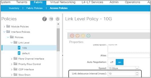
Cisco APIC Design Considerations
The Cisco Application Policy Infrastructure Controller (APIC) is a clustered network control and policy system that provides image management, bootstrapping, and policy configuration for the Cisco ACI fabric.
Cisco APICs can be of different kinds based on the scale requirements: APIC-M up to 1200 edge ports, APIC-L for more than 1200 edge ports. There are multiple generations of APIC clusters where the clusters labeled with a trailing 1 are the older ones and the ones with a trailing 3 and the upcoming ones labeled with a trailing 4 are the newer ones.
The Cisco APIC provides the following control functions:
● Policy manager: Manages the distributed policy repository responsible for the definition and deployment of the policy-based configuration of Cisco ACI.
● Topology manager: Maintains up-to-date Cisco ACI topology and inventory information.
● Observer: The monitoring subsystem of the Cisco APIC; serves as a data repository for Cisco ACI operational state, health, and performance information.
● Boot director: Controls the booting and firmware updates of the spine and leaf switches as well as the Cisco APIC elements.
● Appliance director: Manages the formation and control of the Cisco APIC appliance cluster.
● Virtual machine manager (or VMM): Acts as an agent between the policy repository and a hypervisor and is responsible for interacting with hypervisor management systems such as VMware vCenter.
● Event manager: Manages the repository for all the events and faults initiated from the Cisco APIC and the fabric switches.
● Appliance element: Manages the inventory and state of the local Cisco APIC appliance.
Cisco APICs are equipped with two Network Interface Cards (NICs) for fabric connectivity. These NICs should be connected to different leaf switches for redundancy. Cisco APIC connectivity is automatically configured for active-backup teaming, which means that only one interface is active at any given time. You can verify (but not modify) this configuration from the Bash shell under /proc/net/bonding.
Figure 24 shows a typical example of the connection of the Cisco APIC to the Cisco ACI fabric.
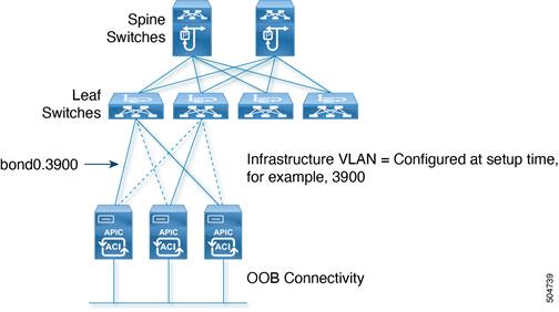
Cisco APIC software creates bond0 and bond0 infrastructure VLAN interfaces for in-band connectivity to the Cisco ACI leaf switches. It also creates bond1 as an out-of-band (OOB) management port.
The network interfaces are as follows:
● bond0: This is the NIC bonding interface for in-band connection to the leaf switch. No IP address is assigned for this interface.
● bond0.<infra VLAN>: This subinterface connects to the leaf switch. The infra VLAN ID is specified during the initial Cisco APIC software configuration. This interface obtains a dynamic IP address from the pool of TEP addresses specified in the setup configuration.
● bond1: This is the NIC bonding interface for OOB management. No IP address is assigned. This interface is used to bring up another interface called oobmgmt.
● oobmgmt: This OOB management interface allows users to access the Cisco APIC. The IP address is assigned to this interface during the Cisco APIC initial configuration process in the dialog box.
Port tracking and Cisco APIC Ports
The port tracking feature is described in the "Designing the fabric access / Port Tracking" section. The port tracking configuration is located under System > System Settings > Port Tracking. Port tracking is a useful feature to ensure that server NICs are active on leaf switches that have fabric connectivity to the spine switches. By default, port tracking doesn’t bring down Cisco APIC ports, but starting in Cisco ACI 5.0(1), there’s an option called "Include APIC Ports when port tracking is triggered". If this option is enabled, Cisco APIC also brings down leaf switch ports connected to Cisco APIC ports if the fabric uplinks go down .
In-Band and Out-of-Band Management of Cisco APIC
When bringing up the Cisco APIC, you enter the management IP address for OOB management as well as the default gateway. The Cisco APIC is automatically configured to use both the OOB and the in-band management networks. If later you add an in-band management network, the Cisco APIC will give preference to the in-band management network connectivity.
You can control whether Cisco APIC prefers in-band or out-of-band connectivity by configuring Cisco APIC connectivity preferences under Fabric > Fabric Policies > Global Policies.
You can also configure static routes for the Cisco APIC by using the in-band management EPG (Tenant mgmt > Node Management EPG > In-Band EPG – default) configuration as described in the "Fabric infrastructure / In-Band and Out-of-Band Management" section.
Internal IP Address Used for Apps
The Cisco ACI 2.2 and later releases have the ability to host applications that run on Cisco APIC itself. This is done with a container architecture whose containers are addressed with IP addresses in the 172.17.0.0/16 subnet. At the time of this writing, this subnet range is not configurable, hence when configuring Cisco APIC management connectivity, make sure that this IP address range does not overlap with management IP addresses or with management stations.
Cisco APICs discover the IP addresses of other Cisco APICs in the cluster using an LLDP-based discovery process. This process maintains an appliance vector, which provides mapping from a Cisco APIC ID to a Cisco APIC IP address and a universally unique identifier (UUID) for the Cisco APIC. Initially, each Cisco APIC has an appliance vector filled with its local IP address, and all other Cisco APIC slots are marked as unknown.
Upon switch reboot, the policy element on the leaf switch gets its appliance vector from the Cisco APIC. The switch then advertises this appliance vector to all its neighbors and reports any discrepancies between its local appliance vector and the neighbors’ appliance vectors to all the Cisco APICs in the local appliance vector.
Using this process, Cisco APICs learn about the other Cisco APICs connected to the Cisco ACI fabric through leaf switches. After the Cisco APIC validates these newly discovered Cisco APICs in the cluster, the Cisco APICs update their local appliance vector and program the switches with the new appliance vector. Switches then start advertising this new appliance vector. This process continues until all the switches have the identical appliance vector, and all of the Cisco APICs know the IP addresses of all the other Cisco APICs.
To support greater scale and resilience, Cisco ACI uses a concept known as data sharding for data stored in the Cisco APIC. The basic theory behind sharding is that the data repository is split into several database units, known as shards. Data is placed in a shard, and that shard is then replicated three times, with each replica assigned to a Cisco APIC appliance, as shown in Figure 25.
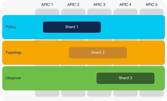
Figure 25 shows that the policy data, topology data, and observer data are each replicated three times on a cluster of five Cisco APICs.
In a Cisco APIC cluster, there is no one Cisco APIC that acts as a leader for all shards. For each replica, a shard leader is elected, with write operations occurring only on the elected leader. Therefore, requests arriving at a Cisco APIC are redirected to the Cisco APIC that carries the shard leader.
After recovery from a "split-brain" condition in which Cisco APICs are no longer connected to each other, automatic reconciliation is performed based on timestamps.
The Cisco APIC can expand and shrink a cluster by defining a target cluster size.
The target size and operational size may not always match. They will not match when:
● The target cluster size is increased.
● The target cluster size is decreased.
● A controller node has failed.
When a Cisco APIC cluster is expanded, some shard replicas shut down on the old Cisco APICs and start on the new Cisco APICs to help ensure that replicas continue to be evenly distributed across all Cisco APICs in the cluster.
When you add a node to the cluster, you must enter the new cluster size on an existing node.
If you need to remove a Cisco APIC node from the cluster, you must remove the appliance at the end. For example, you must remove node number 4 from a 4-node cluster; you cannot remove node number 2 from a 4-node cluster.
Each replica in the shard has a use preference, and write operations occur on the replica that is elected leader. Other replicas are followers and do not allow write operations.
If a shard replica residing on a Cisco APIC loses connectivity to other replicas in the cluster, that shard replica is said to be in a minority state. A replica in the minority state cannot be written to (that is, no configuration changes can be made). However, a replica in the minority state can continue to serve read requests. If a cluster has only two Cisco APIC nodes, a single failure will lead to a minority situation. However, because the minimum number of nodes in a Cisco APIC cluster is three, the risk that this situation will occur is extremely low.
Note: When bringing up the Cisco ACI fabric, you may have a single Cisco APIC or two APICs before you have a fully functional cluster. This is not the desired end state, but Cisco ACI lets you configure the fabric with one Cisco APIC or with two Cisco APICs because the bootstrap is considered an exception.
The Cisco APIC is always deployed as a cluster of at least three controllers, and at the time of this writing, the cluster can be increased to five controllers for one Cisco ACI pod or to up to seven controllers for multiple pods. You may want to configure more than three controllers, primarily for scalability reasons.
Note Refer to the verified scalability guide for information about how many controllers you need based on how many leaf switches you are planning to deploy:
https://www.cisco.com/c/en/us/td/docs/dcn/aci/apic/6x/verified-scalability/cisco-aci-verified-scalability-guide-601.html
This mechanism helps ensure that the failure of an individual Cisco APIC will not have an impact because all the configurations saved on a Cisco APIC are also stored on the other two controllers in the cluster. In that case, one of the remaining two backup Cisco APICs will be promoted to primary.
If you deploy more than three controllers, not all shards will exist on all Cisco APICs. In this case, if three out of five Cisco APICs are lost, no replica may exist. Some data that is dynamically generated and is not saved in the configurations may be in the fabric, but not on the remaining Cisco APICs. To restore this data without having to reset the fabric, you can use the fabric ID recovery feature.
The standby Cisco APIC is a controller that you can keep as a spare, ready to replace any active Cisco APIC in a cluster in one click. This controller does not participate in policy configurations or fabric management. No data is replicated to it, not even administrator credentials.
In a cluster of three Cisco APICs + 1 standby, the controller that is in standby mode has, for instance, a node ID of 4, but you can make the controller active as node ID 2 if you want to replace the Cisco APIC that was previously running with node ID 2.
If all the fabric controllers are lost and you have a copy of the configuration, you can restore the VXLAN network identifier (VNID) data that is not saved as part of the configuration by reading it from the fabric, and you can merge it with the last-saved configuration by using fabric ID recovery.
In this case, you can recover the fabric with the help of the Cisco® Technical Assistance Center (TAC).
The fabric ID recovery feature recovers all the TEP addresses that are assigned to the switches and node IDs. Then this feature reads all the IDs and VTEPs of the fabric and reconciles them with the exported configuration.
The recovery can be performed only from a Cisco APIC that is already part of the fabric.
Summary of Cisco APIC design considerations
Design considerations associated with Cisco APICs are as follows:
● Each Cisco APIC should be dual-connected to a pair of leaf switches. vPC is not used, so you can connect to any two leaf switches.
● Consider enabling port tracking and "Include APIC Ports when port tracking is triggered."
● Ideally, Cisco APIC servers should be spread across multiple leaf switches.
● Adding more than three controllers does not increase high availability, because each database component (shard) is replicated a maximum of three times. However, increasing the number of controllers increases control-plane scalability.
● Consider using a standby Cisco APIC.
● You should consider the layout of the data center to place the controllers in a way that reduces the possibility that the remaining controllers will be in read-only mode, or that you will have to perform fabric ID recovery.
● You should periodically export the entire XML configuration file. This backup copy does not include data such as the VNIs that have been allocated to bridge domains and VRF instances. Run-time data is regenerated if you restart a new fabric, or it can be rebuilt with fabric ID recovery.
Cisco ACI Objects Design Considerations
The Cisco ACI configuration is represented in the form of objects to make the reuse of configurations easy and avoid repetitive operations, which are more prone to human errors. Although you could still configure each single piece repetitively like a traditional switch, you should avoid doing so because it makes the configuration much more complex in Cisco ACI. In this section, we provide some guidelines regarding Cisco ACI object configuration design, such as what to reuse and what not to reuse.
The Cisco APIC management model divides the Cisco ACI fabric configuration into these two categories:
● Fabric infrastructure configurations: This is the configuration of the physical fabric in terms of vPCs, VLANs, loop prevention features, underlay BPG protocol, and so on.
● Tenant configurations: These configurations are the definition of the logical constructs, such as application profiles, bridge domains, and EPGs.
In each category, very roughly speaking, there are objects to be referenced (reused) and objects that reference others. In simple cases, objects to be referenced tend to be called policies in the Cisco APIC GUI, while other objects tend to be called profiles. Every object is also technically a policy.
Most of the time, each type of policy has a default policy that is referenced by all related objects unless specified otherwise. We recommend that you create non-default objects for your purpose so that your configuration changes do not affect objects that you didn’t specifically intend to modify.
The following sections provide guidelines with some examples.
Fabric Infrastructure Configurations
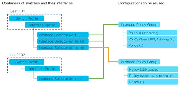
Let’s use fabric access policies to discuss an example guideline for fabric infrastructure configurations.
The following ordered list explains the guideline depicted in Figure 26.
1. Create a fixed switch and interface profile per node and per vPC pair.
For instance, leaf 101, leaf 102 and leaf101-102.
2. Create the interface policies to be reused.
For instance, CDP policies for CDP_Enabled and CDP_Disable, or link level policies for "Speed 10G, Auto Negotiation On," and "Speed 1G, Auto Negotiation Off."
3. Create reuseable interface policy groups as a set of interface policies.
For instance, a policy group for server group A, and a policy group for server group B.
In the case of a PC/vPC, do not reuse interface policy groups because interfaces in the same interface policy group are considered as a member of the same PC/vPC.
You can choose to create multiple interface profiles per node and use profiles as a logical container per usage, such as VMM connectivity and bare metal server connectivity. However, interface policy groups can achieve a similar purpose and too many levels of logical separations tend to make the configuration more complex. Hence, we typically recommend following the above example regarding how to position each object and which one should be reused.
Then, you can group multiple interface policy groups using the Attachable Access Entity Profile (AAEP) as an interface pool. Then, bind AAEP(s) and a VLAN pool using a domain such as physical domain to define which VLANs can be used on which interfaces. See the "Designing the fabric access" section for details on the functionality of each object.
In the tenant, examples of objects that should be reused are protocol policies, such as the OSPF interface policy for the network type, the hello interval, match rules and set rules for route maps (route profiles), or the endpoint retention policy for the endpoint aging timer.
These policies are reused and referenced by EPGs, bridge domains, VRF instances, L3Outs, and so on. You can define the policies in tenant common so that other tenants can use them without duplicating policies with the same parameters.
Tenant common is a special tenant that can share its objects with other tenants as a common resource. However, sometimes you may want to duplicate policies in individual tenants on purpose because changes to the policies in tenant common will impact any tenants that use the common policies.
Another example of tenant objects to be reused is a filter for contracts, such as ICMP and HTTP. In general, contracts should be created in each tenant instead of tenant common, unless there are specific requirements. This is to avoid allowing unexpected traffic across tenants by mistake. However, using filters from tenant common in different contracts from multiple tenants do not pose such a concern. Hence, you can create filters with some common network parameters, such as SSH and HTTP, in tenant common, and reuse the filters from contracts in other tenants. Refer to the Cisco ACI Contract Guide for some scenarios where you want to create contracts in tenant common.
Unlike the interface profiles, which are just containers in Fabric Access Policies, tenant objects such as EPGs, bridge domains, VRF instances, L3Outs are more than a container. They define how your networks and security are structured. Check the "Designing the tenant network" section for details on how those can be and should be structured.
On top of understanding how your configurations should be structured, a clear and consistent naming convention for each object is also important to aid with manageability and troubleshooting. We highly recommend that you define the policy-naming convention before you deploy the Cisco ACI fabric to help ensure that all policies are named consistently.
Table 2 Sample naming conventions
| Type |
Syntax |
Examples |
|
| Tenants |
|||
| Tenants |
[Function] |
Production Development |
|
| VRFs |
[Function] |
Trusted Untrusted |
Production Development |
| Bridge Domains |
[Function] |
Web App |
AppTier1 AppTier2 |
| EPGs (Endpoint Groups) |
[Function] |
Web App |
App_Tier1 App_Tier2 |
| Contracts |
[Prov]_to_[cons] [EPG/Service]_[Function] |
Web_to_App |
App_keepalive |
| Subjects |
[Rulegroup] |
WebTraffic |
keepalive |
| Filters |
[Resource-Name] |
HTTP |
UDP_1000 TCP_2000 |
| Application Profiles |
[Function] |
SAP Exchange |
Sales HumanResource |
| Fabric |
|||
| Domains |
[Function] |
BareMetalHosts VMM |
L2DCI L3DCI |
| VLAN pools |
[Function] |
VMM BareMetalHosts |
L3Out_N7K |
| AAEPs (Attachable Access Entity Profiles) |
[Function] |
VMM BareMetalHosts |
L3Out_N7K |
| Interface Policy Groups |
[Type]_[Functionality] |
PORT_Server_GroupA PORT_Server_GroupB |
vPC_ESXi_Host1 PC_ESXi_Host1 |
| Interface profiles |
[Node] [Node1]_[Node2] (for vPC) |
101 101_102 |
leaf_101 leaf_102 |
| Interface Policies |
[Type] [Enable|Disable] |
CDP_Enable CDP_Disable |
LLDP_Disable LACP_Active |
Although some naming conventions may contain a reference to the type of object (for instance, a tenant may be called Production_TNT or similar), these suffixes are often felt to be redundant, for the simple reason that each object is of a particular class in the Cisco ACI fabric. However, some customers may still prefer to identify each object name with a suffix to identify the type.
Note: In general, we recommend that you avoid using "-" (hyphen) in the name of objects because the distinguished name (DN) uses hyphens to prefix the user configured name. The DN is a unique identifier for each object and often used for API interaction, such as automation or when you need to check details in the object tree. For example, the DN for EPG "web_linux" in application profile "AP1" and tenant "TN1" is "/uni/tn-TN1/ap-AP1/epg-web_linux". Also, you should not use a name with "N-" (N followed by hyphen) as a substring for the object that defines a Layer 4 to Layer 7 device. You should not use a name that includes the substring "C-" for a bridge domain that is used as part of the service graph deployment. Such a bridge domain is one that needs to be selected in the device selection policy configuration of a service graph.
Objects with Overlapping Names in Different Tenants
The names you choose for VRF instances, bridge domains, contracts, and so on are made unique by the tenant in which the object is defined. Therefore, you can reuse the same name for objects that are in different tenants except for those in tenant common.
Tenant common is a special Cisco ACI tenant that can be used to share objects, such as VRF instances and bridge domains, across multiple tenants. For example, you may decide that one VRF instance is enough for your fabric, so you can define the VRF instance in tenant common and use it from other tenants.
Objects defined in tenant common should have a unique name across all tenants. This approach is required because Cisco ACI has a resolution framework that is designed to automatically resolve relationships when an object of a given name is not found in a tenant by looking for it in tenant common as a fallback. See the https://www.cisco.com/c/en/us/td/docs/dcn/aci/apic/5x/aci-fundamentals/cisco-aci-fundamentals-51x/m_policy-model.html#concept_08EC8412BE094A11A34DA1DEDCDF39E9 document, which states:
"In the case of policy resolution based on named relations, if a target MO [Managed Object] with a matching name is not found in the current tenant, the Cisco ACI fabric tries to resolve in the common tenant. For example, if the user tenant EPG contained a relationship MO targeted to a bridge domain that did not exist in the tenant, the system tries to resolve the relationship in the common tenant. If a named relation cannot be resolved in either the current tenant or the common tenant, the Cisco ACI fabric attempts to resolve to a default policy. If a default policy exists in the current tenant, it is used. If it does not exist, the Cisco ACI fabric looks for a default policy in the common tenant. Bridge domain, VRF, and contract (security policy) named relations do not resolve to a default."
If you define objects with overlapping names in tenant common and in a regular tenant, the object of the same name in the tenant is selected instead of the object in tenant common.
For instance, if you defined a bridge domain, BD-1 in tenant Tenant-1 and if you defined VRF VRF-1 in tenant common and also in Tenant-1, you could associate BD-1 to Tenant-1/VRF-1, but Cisco ACI won't let you associate BD-1 to Common/VRF-1. If VRF-1 in Tenant-1 is deleted later on, Cisco APIC will automatically resolve the relation of BD-1 to VRF-1 in tenant Common because the relation points to the VRF with the name VRF-1 and the name resolution within the same tenant failed.
Connectivity Instrumentation Policy
When you create any configuration or design in Cisco ACI, for objects to be instantiated and programmed into the hardware, they must meet the requirements of the object model. If a reference is missing when you are creating an object, Cisco ACI tries to resolve the relation to objects from tenant common. If instead you specify a reference to an object that doesn’t exist or if you delete an object (such as a VRF) and existing objects have a reference to it, Cisco ACI will raise a fault.
For instance, if you create a new bridge domain and you don’t associate the bridge domain with a VRF, Cisco APIC automatically associates your newly created bridge domain with the VRF from tenant common (common/default).
Whether this association is enough to enable bridging or routing from the bridge domain depends on the configuration of the connectivity instrumentation policy (Tenant common > Policies > Protocol Policies > Connectivity Instrumentation Policy).
Fabric-access policies are concerned with classic Layer 2 configurations, such as VLANs, and interface-related configurations, such as LACP, LLDP, Cisco Discovery Protocol, port channels, and vPCs.
These configurations are performed from the Cisco APIC controller from Fabric > Access Policies.
Fabric-access Policy Configuration Model
Interface policies are responsible for the configuration of interface-level parameters, such as LLDP, Cisco Discovery Protocol, LACP, port speed, storm control, and Mis-Cabling Protocol (MCP). Interface policies are brought together as part of an interface policy group.
Each type of interface policy is preconfigured with a default policy. In most cases, the feature or parameter in question is set to disabled as part of the default policy.
We highly recommend that you create explicit policies for each configuration item rather than relying on and modifying the default policy. For example, for LLDP configuration, you should configure two policies, with the name LLDP_Enabled and LLDP_Disabled or something similar, and use these policies when either enabling or disabling LLDP. This helps prevent accidental modification of the default policy, which may have a wide impact.
Note: You should not modify the Fabric Access Policy LLDP default policy because this policy is used by spine switches and leaf switches for bootup and to look for an image to run. If you need to create a different default configuration for the servers, you can create a new LLDP policy and give it a name, and then use this one instead of the policy called default.
The access policy configuration generally follows the workflow shown in Figure 27.
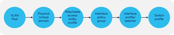
Consider an example where an interface policy group is configured with a certain policy, such as a policy to enable LLDP. This interface policy group is associated with a range of interfaces (for example, 1/1–2), which is then applied to a set of switches (for example, 101 to 104). The administrator now decides that interface 1/2 on a specific switch only (104) must run Cisco Discovery Protocol rather than LLDP. To achieve this, interface override policies can be used.
An interface override policy refers to a port on a specific switch (for example, port 1/2 on leaf node 104) and is associated with an interface policy group. In the example here, an interface override policy for interface 1/2 on the leaf node in question can be configured and then associated with an interface policy group that has been configured with Cisco Discovery Protocol, as shown in Figure 28.
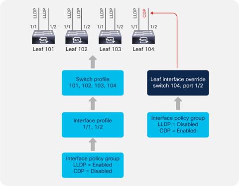
Interface overrides are configured in the Interface Policies section under Fabric Access Policies, as shown in Figure 29.
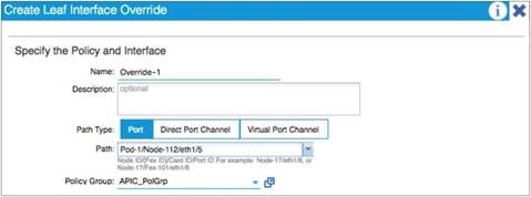
If the interface override refers to a port channel or vPC, a corresponding port channel or vPC override policy must be configured and then referenced from the interface override.
Defining VLAN Pools and Domains
In the Cisco ACI fabric, a VLAN pool is used to define a range of VLAN numbers that will ultimately be applied on specific ports on one or more leaf switches. A VLAN pool can be configured either as a static or a dynamic pool or even a mix of the two:
● Static pools: These are generally used for hosts and devices that will be manually configured in the fabric. For example, bare-metal hosts or Layer 4 to Layer 7 service devices.
● Dynamic pools: These are used when the Cisco APIC needs to allocate VLANs automatically. For instance, when using VMM integration. When associating a dynamic pool to an EPG (using a VMM domain), Cisco APIC chooses which VLAN to assign to the virtualized host port group. Similarly, when configuring a service graph with a virtual appliance using VMM integration, Cisco ACI does all of the following: it allocates the VLANs for the virtual appliance port groups dynamically, it creates port groups for the virtual appliance and programs the VLAN, and it associates the vNICs to the automatically created port groups.
● Dynamic pool including static ranges: You can also define a dynamic pool that includes both a dynamic VLAN range and a static range. When associating such a pool to an EPG (using a VMM domain), this gives you the option to either let Cisco APIC pick a VLAN from the pool or to enter manually a VLAN for this EPG (from the static range). When entering a VLAN manually for an EPG associated with a VMM domain, Cisco APIC programs the VLAN that you entered on the virtualized host port group.
A common practice is to divide VLAN pools into functional groups, as shown in Table 3.
| VLAN range |
Type |
Use |
|
||
| 1000 – 1100 |
Static |
Bare-metal hosts |
|||
| 1101 – 1200 |
Static |
Firewalls |
|||
| 1201 – 1300 |
Static |
External WAN routers |
|||
| 1301 – 1400 |
Dynamic |
Virtual machines |
|||
A domain is used to define the scope of VLANs in the Cisco ACI fabric. In other words, where and how a VLAN pool will be used. There are a number of domain types: physical, virtual (VMM domains), external Layer 2, and external Layer 3. It is common practice to have a 1:1 mapping between a VLAN pool and a domain.
A VLAN pool consists of one or more ranges. It is considered best practices not to define just one big range, rather multiple ranges, for instance instead of configuring a single range from 1000 to 2000, you could define 10 ranges of 100 VLANs each. This is because at some point you may need to modify the VLAN pool and removing/adding back a modified range of ˜100 VLANs is less disruptive than modifying a single range of 1000 VLANs.
When choosing VLAN pools, keep in mind that if the servers connect to Cisco ACI using an intermediate switch or a Cisco UCS Fabric Interconnect, you need to choose a pool of VLANs that does not overlap with the reserved VLAN ranges of the intermediate devices, which means using VLANs < 3915.
Cisco Nexus 9000, 7000, and 5000 series switches reserve the range 3968 to 4095.
Cisco UCS reserves the following VLANs:
● FI-6200/FI-6332/FI-6332-16UP/FI-6324: 4030-4047. Note vlan 4048 is being used by VSAN 1
● FI-6454: 4030-4047 (fixed), 3915-4042 (can be moved to a different 128 contiguous VLAN block, but requires a reboot). See the following document for more information:
In order to prevent misconfigurations, we recommend that you enable the domain validation features globally at System Settings > Fabric Wide Settings.
Even without validations being enabled, ACI raises Fault F0467 "Configuration failed for <static path> due to Invalid Path Configuration" if an EPG is configured with a static {port , VLAN} where a domain containing this VLAN is not present, but this won’t prevent traffic forwarding. In order to prevent traffic forwarding in case of misconfiguration you need to enable “Enforce Domain Validation”.
There are two configurable options:
● Enforce Domain Validation: this validation prevents traffic forwarding on the {port, VLAN} specified by an EPG static port if the EPG doesn’t have a domain configured for that VLAN. Once this validation is turned on it cannot be turned off.
● Enforce EPG VLAN Validation: this validation prevents the assignment of domains with overlapping VLANs to the same EPG
Attachable Access Entity Profiles (AAEPs)
The Attachable Access Entity Profile (AAEP) is used to map domains (physical or virtual) to interface policies, with the end goal of mapping VLANs to interfaces. Typically, AAEPs are used simply to define which interfaces can be used by EPGs, L3Outs, and so on through domains. The deployment of a VLAN (from a VLAN range) on a specific interface is performed using EPG static path binding (and other options that are covered in the "EPG and VLANs" section), which is analogous to configuring switchport access vlan x or switchport trunk allowed vlan add x on an interface in a traditional Cisco NX-OS configuration. You can also configure EPG mapping to ports and VLANs directly on the AAEP. Such a configuration is roughly analogous to configuring switchport trunk allowed vlan add x on all interfaces in the AAEP in a traditional Cisco NX-OS configuration. In addition, AAEPs allow a one-to-many relationship (if desired) to be formed between interface policy groups and domains, as shown in Figure 30.
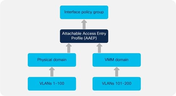
In the example in Figure 30, an administrator needs to have both a VMM domain and a physical domain (that is, using static path bindings) on a single port or port channel. To achieve this, the administrator can map both domains (physical and virtual) to a single AAEP, which can then be associated with a single interface policy group representing the interface or the port channel.
Note: You can have multiple VMM domains mapped to the same AAEP. You can have multiple VMM domains mapped to the same EPG.
The EPG configuration within a tenant defines the mapping between the traffic from an interface (and a VLAN) and a bridge domain. The EPG configuration includes the definition of the domain (physical or virtual) that the EPG belongs to, and the binding to the Cisco ACI leaf switch interfaces and VLANs.
When the EPG configuration deploys a VLAN on a port, the VLAN and the port need to belong to the same domain using a VLAN pool and an AAEP respectively.
For instance, imagine that EPG1 from Tenant1/BD1 uses port 1/1, VLAN10, and that VLAN10 is part of physical domain domain1, that same physical domain domain1 must have been configured on port 1/1 as part of the fabric access AAEP configuration.
Understanding VLAN Use in Cisco ACI and to Which VXLAN They Are Mapped
To understand which VLAN configurations are possible in Cisco ACI, it helps to understand how VLANs are used and how Cisco ACI handles Layer 2 multidestination traffic (broadcast, unknown unicast and multicast). Cisco ACI uses VXLAN to carry both Layer 2 and Layer 3 traffic, hence there is no use for VLANs within the fabric itself. On the other hand, traffic that reaches the front panel ports from servers or external switches is tagged with VLANs. Cisco ACI then encapsulates the traffic and assigns a VXLAN VNID before forwarding it to the spine switches. The VXLAN VNID assignment depends primarily on whether the traffic is switched (Layer 2) or routed (Layer 3), because Layer 2 traffic is assigned the VNID that identifies the bridge domain and Layer 3 traffic is assigned the VNID that identifies the VRF.
The forwarding of Layer 2 multidestination traffic (BUM) is achieved by using a routed multicast tree. Each bridge domain is assigned a multicast group IP outer (GIPo) address, as opposed to group IP inner (GIPi) or the multicast address in the overlay. The bridge domain forwards BUM traffic (for example for a Layer 2 multidestination frame) over the multicast tree of the bridge domain (GIPo). The multidestination tree is built using IS-IS. Each leaf switch advertises membership for the bridge domains that are locally enabled. The multicast tree in the underlay is set up automatically without any user configuration. The roots of the trees are always the spine switches, and traffic can be distributed along multiple trees according to a tag, known as the forwarding tag ID (FTAG).
Frames with a Layer 2 multidestination address are flooded on the bridge domain, which means that the frames are sent out to all the local leaf switch ports and other leaf switches ports that are on the same bridge domain regardless of the encapsulation VLAN used on the port, as long as the ports all belong to the same bridge domain. The traffic is forwarded in the Cisco ACI fabric as a VXLAN packet with VNID of the bridge domain and with the multicast destination address of the bridge domain.
Among the Layer 2 frames that require multidestination forwarding, Cisco ACI handles spanning tree BPDUs in a slightly different way than other frames because to avoid loops and to preserve the access encapsulation VLAN information associated to the BPDU (within the bridge domain), this traffic is assigned the VXLAN VNID that identifies the access encapsulation VLAN (instead of the bridge domain VNID) and flooded to all ports of the bridge domain that carry the same access encapsulation (regardless of the EPG). This behavior also applies more in general to Layer 2 flooding when using the feature called "Flood in Encapsulation". In this document, we refer to this specific encapsulation as the FD_VLAN VXLAN encapsulation or FD_VLAN VNID, or FD VNID for simplicity. The FD_VLAN fabric encapsulation (or FD_VLAN VNID or FD VNID) is different from the bridge domain VNID.
To accommodate all of the above requirements, it is important to distinguish these type of VLANs:
● Access VLAN or access encapsulation: This is the VLAN used on the wire between an external device and the Cisco ACI leaf switch access port
● BD_VLAN (a VLAN locally significant to the leaf switch): This is the bridge domain VLAN. This VLAN is common across all EPGs in the same bridge domain, and is used to implement Layer 2 switching within the bridge domain, among all EPGs. This is mapped to the Fabric Encapsulation VXLAN VNID for the bridge domain (bridge domain VNID) before being forwarded to the spine switches. The bridge domain then encompasses multiple leaf switches. The bridge domain has a local BD_VLAN on each leaf switch, but the forwarding across the leaf switches is based on the bridge domain VNID for Layer 2 flooding.
● FD_VLAN (a VLAN locally significant to the leaf switch): This is a VLAN that does not encompass the entire bridge domain. You can think of it as a "subset" of the bridge domain. This is a Layer 2 domain for the traffic from the same access (encapsulation) VLAN in the same bridge domain, regardless of from which EPG it comes. The traffic that is forwarded according to the FD_VLAN also gets encapsulated in a VXLAN VNID, the FD VNID, before being forwarded to the spine switches. From a user perspective, the FD VNID is relevant for three reasons:
o The ability to forward spanning tree BPDUs
o A feature called "Flood in Encapsulation"
o The fact that endpoint synchronization between vPC peers takes the FD VNID into account, and hence the configuration must guarantee that the same EPG/endpoint gets the same FD VNID on either vPC peer.
BD_VLANs and FD_VLANs are locally significant to the leaf switch. What matters from a forwarding perspective are the bridge domain VNID and the FD VNID.
The FD VNID that a VLAN maps to depends on the VLAN number itself and on the VLAN pool object (and because of this, indirectly also the domain, but if two domains use the same VLAN pool, the same VLAN gets the same FD VNID) that it is from. Defining the same encap VLAN range in two VLAN pools does not result in the same FD VNID being assigned to the same VLAN number. In other words, the FD VNID is a function of the VLAN encapsulation number and the VLAN pool object. Each VLAN on a given bridge domain has a unique FD_VLAN VNID and this number is identical on all leaf switches where the same bridge domain and VLAN are present.
The FD VNID assignment uses the following rules:
● Every access VLAN in a VLAN pool has a corresponding FD VNID irrespective of which EPG in the bridge domain is using that VLAN from the pool. This is again to ensure that STP BPDUs are forwarded across the fabric on the tree of the "FD_VLAN".
● If you create different VLAN pools with the same VLANs and overlapping ranges (or even the same range) Cisco ACI gives the same encapsulation VLAN a different FD VNID depending on which pool it is configured from. For instance, if you have two pools poolA and poolB and both have the range of VLANs 10-20 defined, if you have an EPG associated with VLAN 10 from poolA and another EPG of the same bridge domain associated with VLAN 10 from poolB, these two VLANs are assigned to two different FD VNID encapsulations.
● A given VLAN number (with scope global) on a given leaf switch can get only one FD_VLAN VNID. In other words, if there are two or more configurations that are using the same VLAN encapsulation from different VLAN pools (and typically domains) on a leaf switch, they both use the same FD_VLAN VNID (which FD_VLAN VNID is used can depend on the configuration sequence).
There are designs and configurations where the admin may configure overlapping VLAN pools as part of an AAEP or as part of an EPG configuration. This can happen when the admin defines VLAN pools with overlapping VLANs, which then are assigned to different domains and these domains in their turn are associated to the same AAEP or the same EPG.
Defining domains with overlapping VLAN pools is not a concern if they are used by different EPGs of different bridge domains, potentially with VLAN port scope local if the EPGs map to ports of the same leaf switch.
The problem of overlapping VLANs is primarily related to having an EPG with multiple domains, which contain overlapping VLAN ranges. The main reason to avoid this configuration is the fact that BPDU forwarding doesn’t work correctly within the fabric and also the fact that vPC synchronization may not function because endpoints of the same VLAN may be on mismatched FD_VLAN VNIDs.
In the case of having an EPG with multiple domains mapped to ports configured with a policy group of type vPC with an AAEP with multiple domains if the FD VNID is different between vPC peers, the endpoint synchronization doesn’t work correctly. For this very reason Cisco ACI raises fault F3274 for vPC ports with different FD VNIDs.
Mismatched FD_VLAN VNIDs can also be a problem for orphan ports in a vPC configuration. This is because when two leaf switches are configured as part of a vPC domain, the synchronization of the endpoint information for orphan ports is also based on the vPC "peer-link" (which in ACI is implemented using the fabric links), instead of simply relying on endpoint learning. If you have single homed devices and the ACI leaf switches are configured as a vPC domain, you must ensure that the same FD_VLAN VNID is present on both vPC peers so that the MAC address and IP address of single homed devices are learned by the other vPC peer.
You can easily avoid the potential misconfigurations of using overlapping VLANs by configuring the EPG VLAN validation (System > System Settings > Fabric-Wide Settings > Enforce EPG VLAN Validation), which would prevent the configuration of domains with overlapping VLANs in the same EPG.
The rest of this section describes various EPG and AAEP configurations with VLAN pools that have overlapping VLAN ranges assuming that the EPG VLAN validation is not enabled.
The explanations are organized as follows:
● EPG/AAEPs with multiple domains that point to the same VLAN pool
● EPGs with a single domain and AAEPs with multiple domains
● EPGs with multiple domains and AAEPs with a single domain
● EPGs with multiple domains and AAEPs with multiple domains
Defining multiple domains that have overlapping VLANs pointing to the same VLAN pool, is not a problem as the same VLAN encapsulation maps consistently to the same FD VNID:
● EPG mapped to one domain with a static path to two ports configured respectively with two policy groups pointing to two AAEPs pointing both to the same domain as the EPG and pointing to one VLAN pool
● EPG mapped to one domain with a static path to two ports configured respectively with two policy groups pointing to the same AAEP pointing to the same domain as the EPG and pointing to one VLAN pool
● EPGs mapped to two domains with a static path to two ports configured respectively with two policy groups pointing to two AAEPs pointing each to one of the domains defined in the EPGs with both domains pointing to the same VLAN pool (one single VLAN pool referred by two domains).
In summary, if you map policy groups that use AAEPs that point to the same VLAN pool to interfaces that carry traffic from the same bridge domain, then the FD VNID assignment is consistent for the same VLAN encapsulation.
Having domains that map to different VLAN pools with overlapping VLAN ranges in the same AAEP per se is not a problem, but it can be depending on the EPG configuration:
● If there is only one EPG in a bridge domain that contains only one of the domains, this is not an issue because when mapping the EPG configuration to an interface/VLAN, Cisco ACI matches the EPG domain with the domain of the same name contained in the AAEP, and as a result the configuration allows the use of only one VLAN pool, the one that is present both in the EPG configuration and in the AAEP configuration. Remember that on a given leaf switch, a given VLAN can only be used by one EPG in a bridge domain, unless the port local VLAN scope is used.
● If there are multiple EPGs in the same bridge domain using the same VLAN on different leaf switches and some use one domain and others use another domain, the FD VNID assignment will be different between EPGs of the same bridge domain, which could be a problem for BPDU forwarding.
If an EPG is mapped to multiple domains, pointing to different VLAN pools with overlapping VLANs tends to be a problem. If these EPGs are mapped to physical interfaces with different AAEPs, Cisco ACI tries to find the intersection between the domains defined in the EPG and the ones defined in the AAEP.
If:
● EPG1 is associated with domain1 and domain2 on a VLAN that is present in both
● Leaf 1 interface1 is associated with an AAEP with domain1
● Leaf 1 interface2 is associated with an AAEP with domain2
● EPG1 has a static binding with both Leaf 1 interface1 and Leaf 1 interface2
Considering that per leaf switch there can only be one FD_VNID per VLAN encapsulation, unless VLAN scope port local is used, Cisco ACI does the following:
● Cisco ACI assigns traffic from the VLAN on Leaf 1 interface1 to the same BD_VLAN VNID as interface2, and to a FD VNID
● Cisco ACI assigns traffic from the VLAN on Leaf 1 interface 2 to the same BD_VLAN VNID as interface1, and also the same FD VNID as interface1
In theory, the FD VNIDs should be different for interface 1 and interface 2, as the domain that is picked is different, but because only one FD VNID can be used per leaf switch, one of the two interfaces uses the FD VNID of the other. Upon reboot, this assignment could be different. Because of this, this configuration should not be used, as it may work, but after a reboot you may have two vPC pairs with different FD VNIDs for the same encapsulation VLAN. This may cause vPC endpoint synchronization not to work.
Be careful when mapping multiple domains with VLAN pools containing overlapping VLAN ranges to the same EPG and also to the same AAEP, because the FD VNID can be nondeterministic. An example of such a configuration is an EPG with multiple domains and interface policy groups pointing to one AAEP pointing to multiple domains with each domain pointing to a different VLAN pool (different VLAN pools with overlapping VLANs).
This configuration is not ok either for the purpose of BPDU forwarding within the same bridge domain nor for vPC synchronization between vPC peers, because the vPC synchronization requires the FD VNID to be the same on both vPC peers.
With this configuration, the fabric encapsulation for the given EPG and VLAN on each leaf switch/interface may not be consistent or may change after a clean reboot or an upgrade of the leaf switch.
The following table summarizes the examples:
Table 4 Various outcomes for configurations with overlapping VLAN pools
|
|
Example1 |
Example 2 |
Example 3 |
Example 4 |
||||
| EPGs on the same bridge domain |
EPG1 (domain1) |
EPG1 (domain1) or EPG1 (domain1, domain2) |
EPG2 (domain 2) or EPG1 (domain1, domain 2) |
EPG1(domain1) |
EPG1(domain1)
|
EPG2 (domain2)
|
||
| Interface Policy-Group
|
Policy-Group 1 |
Policy-Group 2 |
Policy-Group 1 |
Policy-Group 2 |
Policy-Group 1 |
Policy-Group 2 |
Policy-Group 1 |
Policy-Group 2 |
| AAEP |
Same AAEP |
AAEP 1 |
AAEP 2 |
AAEP 1 |
AAEP 2 |
AAEP 1 |
AAEP 2 |
|
| Domain |
Domain 1 |
Domain 1 |
Domain 2 |
Domain 1 |
Domain 1 |
Domain 2 |
||
| VLAN pool |
VLAN pool 1 |
VLAN pool 1 |
VLAN pool 1 |
VLAN pool 1 |
VLAN pool 2 |
|||
| Forwarding Result |
Identical FD VNID for the same VLAN in the same bridge domain |
Identical FD VNID for the same VLAN in the same bridge domain |
Identical FD VNID for the same VLAN in the same bridge domain |
Identical FD VNID for the same VLAN in the same bridge domain |
Identical FD VNID for the same VLAN in the same bridge domain |
Identical FD VNID for the same VLAN in the same bridge domain |
Different FD VNID for the same VLAN in the same bridge domain |
Different FD VNID for the same VLAN in the same bridge domain |
If you have an EPG with two domains that contain overlapping VLAN pools with a static path configuration to a vPC, and if the corresponding vPC policy group contains the two domains, the FD VNID for the encapsulation VLAN is not deterministic, which can be a problem for endpoint synchronization.
The configuration of an EPG with multiple VMM domains for the same path, with the VMM domains using the same VLAN pool is a valid configuration. However, as of Cisco ACI 5.1(2e), if "Enforce EPG VLAN Validation" is enabled, Cisco ACI rejects this configuration.
On a single leaf switch, it is not possible to re-use a VLAN in more than one EPG. To be able to re-use a VLAN for a different EPG, which must be in a different bridge domain, you need to change the Layer 2 interface VLAN scope from "Global" to "Port Local Scope." This configuration is an interface configuration, hence all the VLANs on a given port that is set for VLAN scope port local have scope port local and can be re-used by a different EPG on a different bridge domain, on the same leaf switch.
This can be done by configuring a policy group on a port with a Layer 2 interface policy set with VLAN scope = Port Local Scope: Fabric > Access Policies > Policies > Interface > L2 Interface > VLAN Scope > Port Local Scope.
The other requirement for this feature is that the physical domain and the VLAN pool object of the VLAN that is re-used must be different on the EPGs that re-use the same VLAN.
While this feature provides the flexibility to re-use the same VLAN number on a single leaf switch, from a scalability perspective, measured in terms of port x VLANs per leaf switch, the use of the default (scope Global) provides greater scalability than scope local. Also, be aware that changing from VLAN scope Global to VLAN scope local is disruptive.
Domain and EPG VLAN Validations
To help ensure that the configuration of the EPG with domains and VLANs is correct, you can enable the following validations:
● System > System Settings > Fabric-wide Settings > Enforce Domain Validation: This validation helps ensure that the EPG configuration includes a domain.
● System > System Settings > Fabric-wide Settings > Enforce EPG VLAN Validation: This validation helps ensure that the EPG configurations don’t include domains with overlapping VLAN pools.
This configuration is illustrated in Figure 31.
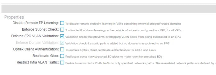
It is a best practice to enable these two validations despite the stringent restriction for multiple VLAN pools with an overlapping VLAN range in the same EPG, even if those VLAN pools are configured in an appropriate way. This is because an inappropriate use of overlapping VLAN pools, such as the vPC issue mentioned before, has a risk of an unexpected outage. You may be surprised by such an outage because the configuration may not cause any issues until you reboot or upgrade the switches.
An appropriate use case of overlapping VLAN pools is to separate STP BPDU failure domains, for instance one STP domain per pod even when an EPG is expanded across pods with the same encap VLAN ID. Domain 1 contains an AAEP for interfaces in pod 1 and domain 2 contains an AAEP for pod2, while each domain has its own VLAN pool with the overlapping VLAN ID range. Configuring one VLAN pool for each pod with the same VLAN range allows you to assign a different FD VNID to the same VLAN ID for each pod. This is helpful to minimize the impact of STP TCN that can be triggered by a topology change, such as an interface flap in the external network connected to Cisco ACI. When STP TCN is propagated throughout the STP domain, normal switches flush the MAC address table. Cisco ACI switches do the same and flush the endpoint table for the given VLAN. If a constant interface flap happens within the external network, this flap generates multiple STP TCNs and the Cisco ACI switches in the same STP domain will receive the TCNs. As a result, the endpoint table on those switches keeps getting flushed. If STP BPDU domains are closed within each pod, the impact of such an event is also closed within each pod. However, if the external networks connected to each pod are connected to each other using external links, you should have one STP BPDU domain across pods to avoid a potential Layer 2 loop using the external links and IPN.
If you feel confident on the design of VLAN pools after reading this section, you can opt to not rely on the EPG VLAN Validation option and have more flexible STP domain separations within Cisco ACI.
Cisco Discovery Protocol, LLDP, and Policy Resolution
In Cisco ACI VRF instances and bridge domains, Switch Virtual Interfaces (SVIs) are not configured on the hardware of the leaf switch unless there are endpoints on the leaf switch that require an SVI. Cisco ACI determines whether these resources are required on a given leaf switch based on Cisco Discovery Protocol, LLDP, or OpFlex (when the servers support it).
Note: For more information, see the "Resolution and deployment immediacy of VRF instances, bridge domains, EPGs, and contracts" section later in this document.
Therefore, the Cisco Discovery Protocol (CDP) or LLDP configuration is not just for operational convenience, but is necessary for forwarding to work correctly.
Be sure to configure Cisco Discovery Protocol or LLDP on the interfaces that connect to virtualized servers.
In Cisco ACI, by default, LLDP is enabled with an interval of 30 seconds and a holdtime of 120 seconds. The configuration is global and can be found in Fabric > Fabric Policies > Global.
CDP uses the usual Cisco CDP timers with an interval of 60s and a holdtime of 120s.
If you do not specify any configuration in the policy group, LLDP, by default, is running and CDP is not. The two are not mutually exclusive, so if you configure CDP to be enabled on the policy group, Cisco ACI generates both CDP and LLDP packets.
If you are using fabric extenders (FEX) in the Cisco ACI fabric, support for the Cisco Discovery Protocol has been added in Cisco ACI release 2.2. If you have a design with fabric extenders and you are running an older version of Cisco ACI, you should configure LLDP for fabric extender ports.
Give special considerations to the LLDP and CDP configuration with VMM integration with VMware vSphere, as these protocols are key to resolving the policies on the leaf switches. The following key considerations apply:
● VMware vDS supports only one of CDP/LLDP, not both at the same time.
● LLDP takes precedence if both LLDP and CDP are defined.
● To enable CDP, the policy group for the interface should be configured with LLDP disabled and CDP enabled.
● By default, LLDP, is enabled and CDP is disabled.
If virtualized servers connect to the Cisco ACI fabric through other devices, such as blade switches using a Cisco UCS fabric interconnect, be careful when changing the management IP address of these devices. A change of the management IP address may cause flapping in the Cisco Discovery Protocol or LLDP information, which could cause traffic disruption while Cisco ACI policies are being resolved.
If you use virtualized servers with VMM integration, make sure to read the "NIC Teaming Configurations for Virtualized Servers with VMM Integration" section.
Port Channels and Virtual Port Channels
In Cisco ACI, vPCs are used to connect leaf switch front panel ports to servers, Layer 3 devices, or other Layer 2 external networks.
vPCs provide the following technical benefits:
● They eliminate Spanning Tree Protocol (STP) blocked ports
● They use all available uplink bandwidth
● They allow dual-homed servers to operate in active-active mode
● They provide fast convergence upon link or device failure
● They offer dual active/active default gateways for servers
vPC also leverages native split horizon/loop management provided by the port channeling technology: a packet entering a port channel cannot immediately exit that same port channel.
vPC leverages both hardware and software redundancy aspects:
● vPC uses all port channel member links available so that in case an individual link fails, the hashing algorithm will redirect all flows to the remaining links.
● A vPC domain is composed of two peer devices. Each peer device processes half of the traffic coming from vPCs. In case a peer device fails, the other peer device will absorb all the traffic with minimal convergence time impact.
● Each peer device in the vPC domain runs its own control plane, and both devices work independently. Any potential control plane issues stay local to the peer device and does not propagate or impact the other peer device.
From a Spanning Tree standpoint, vPC eliminates STP blocked ports and uses all available uplink bandwidth. Spanning Tree can be used as a failsafe mechanism and does not dictate the Layer 2 path for vPC-attached devices.
Which leaf switches are part of a vPC pair is determined by the configuration of what ACI calls (depending on the software version) a vPC Protection Group, a virtual Port Channel Policy, or virtual Port Channel Security. You can perform the configuration of which leaf switches are part of the same vPC pair from the following configuration path: Fabric > Access Policies > Policies > Switch > Virtual Port Channel default > Explicit vPC Protection Groups.
As a result of this configuration, Cisco APIC assigns a TEP IP address to each vPC pair. The endpoints attached to the leaf switches through a vPC that are discovered by ACI are learned in the spine switch proxy as coming from the TEP IP address of the vPC pair (instead of the TEP IP address of the leaf switch itself). In case the link to one of the vPC leaf switches goes down and the endpoint is connected to only one of the two vPC pairs, the endpoint MAC and IP addresses are updated in the spine switch proxy and associated with the leaf switch TEP IP address.
In ACI vPCs do not require a dedicated peer-link. The peer-link and the peer keepalive communications are automatically implemented by ACI through the ZMQ protocol.
● The ZMQ protocol is used to synchronize information between the vPC peers. The ZMQ protocol is used to synchronize the endpoint MAC and IP information for both vPC connected ports as well as orphan ports. The VLANs of the ports must match between the vPC pairs for the synchronization to work.
● The peer keepalive function is achieved via IS-IS: the ACI software component called vPC manager registers with URIB for peer route notifications. When another vPC manager registers with URIB, IS-IS discovers the route to the vPC peer and URIB notifies the vPC manager of the leaf switch. When a vPC peer goes down, the route disappears from IS-IS and the vPC manager is notified.
You can check the ZMQ Channel by using this command:
show system internal vpcm zmq statistics
In a vPC pair there is one node which is vPC primary and the other is vPC secondary, this information is used in case of split-brain scenarios for ACI to decide which links to shut down or keep up.
One vPC peer is Designated Forwarder (DF) the other is a non-DF for multidestination traffic. If the source of multidestination traffic is behind a vPC, the traffic is sent locally to the vPCs. If the source of multi-destination traffic is not on the same vPC pair, the traffic is hashed, and the hash is used to determine which leaf switch is the vPC DF for that flow.
Static Port Channel, LACP Active, LACP Passive
A vPC can be configured in static mode, or it can be configured with the Link Aggregation Control Protocol (LACP), IEEE 802.3ad.
When using LACP you can choose between:
● LACP active: The Cisco ACI leaf switch puts a port into an active negotiating state, in which the port initiates negotiations with remote ports by sending LACP packets. This option is typically the preferred option when Cisco ACI leaf switch ports connect to servers.
● LACP passive: The Cisco ACI leaf switch places a port into a passive negotiating state, in which the port responds to LACP packets it receives, but does not initiate LACP negotiation.
The LACP protocol uses the system-mac and the key to decide which ports can be bundled together. The LAG ID format is Lag Id: [system-priority, system-mac, key, port-priority, port].
With LACP negotiated port channels, making the system-mac unique prevents the bundling of unrelated ports. In vPCs, this is achieved by assigning a unique domain-id to each vPC pair. In ACI as in NXOS, the domain-id defined for the vPC domain is used to generate the system MAC address (or system ID) of the system comprised of the vPC peers. In ACI, the domain-id is configured as part of the vPC explicit protection group.
The generated vPC system-mac in ACI is has the format of 00:23:04:ee:be:<domain-id>.
The other information that LACP uses to decide how to bundle the ports is the actor key. In LACP, terminology the actor is the device on which you are configuring LACP and the partner is the other device with which the actor device negotiates the port channel. The actor key is basically the port channel number, which in ACI is different when defining a different policy group type vPC. ACI translates the policy group type vPC into a dynamically-generated port channel number.
As a result of this, it is considered best practices to configure vPCs as follows:
● Assigning a different domain-id to each vPC pair
● Using a different policy group type vPC for ports in different vPC domains
Even if the recommendation is to use different domain-ids for different vPC pairs, in ACI re-using the same domain-id in different vPC pairs is not a problem because even if you re-use the same policy group type vPC on the same port number, the "key" in the Lag Id: [system-priority, system-mac, key, port-priority, port] is different on different vPC pairs.
The same is true for re-using the same policy group of type vPC on different vPC pairs. We do not recommend that you do this, but the port channel number or key that is autogenerated is unlikely to be identical to the ones of another vPC pair, so this is unlikely to result in an incorrect port channel bundling.
Cisco ACI offers additional modes to "bundle" links to specifically support connectivity to virtualized hosts integrated using the VMM domain. These modes are called MAC pinning, MAC pinning with Physical NIC Load, and Explicit Failover Order. These options are covered in the "NIC Teaming Configurations for Virtualized Servers with VMM Integration" section.
The LACP options are configured as part of the Fabric > Access Policies > Policies > Interface > Port Channel policy configuration and associated with the policy group.
The classic vPC topologies can be implemented with Cisco ACI: single-sided vPC and double-sided vPC. A vPC can be used in conjunction with an L3Out and routing peering over vPC works without special considerations. Different from NX-OS, a FEX cannot be connected to Cisco ACI leaf switches using a vPC.
Cisco ACI performs load distribution of the traffic destined to a vPC connected to a MAC and IP address by hashing the outer VXLAN UDP headers. The hashing ensures traffic distribution for different traffic flows encapsulated in VXLAN because the UDP source port (on the outer VxLAN header) is derived from the inner packets five tuple as described in rfc7348:
● Source Port: It is recommended that the UDP source port number be calculated using a hash of fields from the inner packet -- one example being a hash of the inner Ethernet frame's headers. This is to enable a level of entropy for the ECMP/load-balancing of the VM-to-VM traffic across the VXLAN overlay. When calculating the UDP source port number in this manner, it is recommended that the value be in the dynamic/private port range 49152-65535 [RFC6335].
As a result, the flow distribution for traffic destined to a vPC is achieved by performing ECMP on the VXLAN packets. In case of multiple flows traffic is distributed to both vPC leaf switches and as a result to vPC member ports of both vPC peers.
You can also choose which hashing configuration to use for a port channel if you select the option "Symmetric hashing" in the port channel policy control configuration. Cisco ACI offers the following options:
● Source IP address
● Destination IP address
● Source Layer 4 port
● Destination Layer 4 port
Only one hashing option can be chosen per leaf switch.
The port channel hashing choice is applied locally to each leaf switch, so if you have one single link per leaf switch, you cannot expect the port channel hashing choice to have any influence on the vPC.
Because of this, you can configure port channel hashing on individual leaf switches to be symmetric, but vPC symmetric hashing is not possible.
Configuration for Faster Convergence with VPCs
Starting with Cisco ACI release 3.1, the convergence times for several failure scenarios have been improved. One such failure scenario is the failure of a vPC from a server to the leaf switches. To further improve the convergence times, you should configure the link debounce interval timer under the Link Level Policies for 10ms, instead of the default of 100ms.
Port Channels and Virtual Port Channels Configuration Model in Cisco ACI
In a Cisco ACI fabric, port channels and vPCs are created using interface policy groups. You can create interface policy groups under Fabric > Access Policies > Interface Profiles > Policy Groups > Leaf Policy Groups.
A policy group can be for a single interface, for a port channel or for a vPC, and for the purpose of this discussion the configurations of interest are the port channel policy group and the vPC policy group:
● The name that you give to a policy group of the port channel type is equivalent to the Cisco NX-OS command channel-group channel-number.
● The name that you give to a policy group of the vPC type is equivalent to the channel-group channel-number and vpc-number definitions.
The interface policy group ties together a number of interface policies, such as Cisco Discovery Protocol, LLDP, LACP, MCP, and storm control. When creating interface policy groups for port channels and vPCs, it is important to understand how policies can and cannot be reused. Consider the example shown in Figure 32.
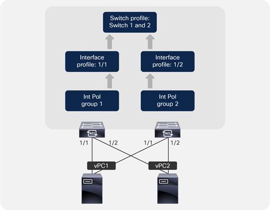
In this example, two servers are attached to the Cisco ACI leaf switch pair using vPCs. In this case, two separate interface policy groups must be configured, associated with the appropriate interface profiles (used to specify which ports will be used), and assigned to a switch profile. A common mistake is to configure a single interface policy group and attempt to reuse it for multiple port channels or vPCs on a single leaf switch. However, using a single interface policy group and referencing it from multiple interface profiles will result in additional interfaces being added to the same port channel or vPC, which may not be the desired outcome.
Note: When you assign the same policy group to multiple interfaces of the same leaf switches or of two different leaf switches, you are defining the way that all these interfaces should be bundled together. In defining the name for the policy group, consider that you need one policy group name for every port channel and for every vPC.
A general rule is that a port channel or vPC interface policy group should have a 1:1 mapping to a port channel or vPC.
Bundling in the same vPC interfaces with the same number from different leaf switches (such as interface 1/1 of leaf1 bundled with interface 1/1 of leaf2) is good practice, but it is not mandatory. Configuring the same vPC policy group on two interfaces of different leaf switches, with interfaces of a different number, such as interface 1/1 from leaf1 with interface 1/2 from leaf2, is a valid configuration.
Administrators should not try to reuse port channel and vPC interface policy groups for more than one port channel or vPC. This rule applies only to port channels and vPCs. Re-using leaf switch access port interface policy groups is fine as long as the person who manages the Cisco ACI infrastructure realizes that a configuration change in the policy group applies potentially to a large number of ports.
You might be tempted to use a numbering scheme for port channels and vPCs: for example, PC1, PC2, vPC1, and so on. However, this is not recommended because Cisco ACI allocates an arbitrary number to the port channel or vPC when it is created, and it is unlikely that this number will match, which could lead to confusion. Instead, we recommend that you use a descriptive naming scheme, such as Firewall_Prod_A.
Endpoints connected through a vPC are synchronized between vPC peers, and for this they must be on the same FD_VLAN VNID. If the vPC member ports of the same EPG are on different FD_VLAN VNIDs, Cisco APIC raises a FD_VNID mismatch (F3274) fault.
For the same bridge domain VLAN, the FD_VLAN is the same if there are no domains with overlapping VLANs on the same EPG. If the EPG has multiple domains with overlapping VLANs, then the FD_VLAN varies. For more information, see the "Overlapping VLANs Ranges" section.
When two Cisco ACI leaf switches are configured as a vPC pair, meaning that they are part of the same vPC domain (a vPC protection group in Cisco ACI terminology), the ports that are not part of a vPC policy group are called "orphan" ports. An orphan port is a port configured with a policy group type access or port-channel (but not vPC) on a Cisco ACI leaf switch that is part of a vPC domain.
Endpoints that are on orphan ports are also synchronized between vPC peers (similar to endpoints connected through a vPC), which requires the same VLAN (or to be more accurate, the same FD VNID) to exist on both vPC peers. The requirement is that the same FD_VLAN is present; there is no requirement for the FD_VLAN to be associated with the same port number as the vPC peer. A leaf switch that is member of a vPC pair learns the endpoint IP address and MAC address of a vPC peer leaf switch through vPC synchronization and not through dataplane learning (the entry appears in the leaf switch's show endpoint output as "-O"). If a host is dual attached with a NIC teaming configuration, such as active/standby, this condition is automatically met. If instead the host is single attached to only one Cisco ACI leaf switch, this condition is not met and under normal circumstances this is not a problem. However, it is good practice to make sure that the EPG that has a static port configuration with an orphan port on a leaf switch has the same VLAN encapsulation defined on a static port configuration on the vPC pair leaf switch.
Note A common misconception is that with an active/standby teaming configuration, the same FD_VLAN may not be present on the leaf switch where the standby interface is connected. This is typically not the case because of two reasons. The first reason is that with active/standby teaming, the standby interface is not down. The standby interface is up, but it is not forwarding traffic. The second reason is that with physical domain the resolution immediacy is immediate, so the fact that ACI programs the FD_VLAN is independent of whether the interface is up or down. With VMM domains, if the resolution is on-demand, the FD_VLAN is programmed regardless of the teaming options, as long as there is one VM attached to the port group (EPG).
This requirement instead can cause disruption during migration scenarios where a host interface is moved from one interface that is using a VLAN on a Cisco ACI leaf switch to another interface that is using a different VLAN on the Cisco ACI leaf switch peer. An example is if you move a vNIC of a virtual machine from one port group that has a single VMNIC connected to only one Cisco ACI leaf switch, to another port group that has only one VMNIC connected to the other Cisco ACI leaf switch.
When such a condition exists, Cisco ACI raises a fault. So, before migrating a vNIC from one VLAN on an orphan port to a different VLAN on another orphan port of a different Cisco ACI leaf switch, verify whether this condition exists. A simple solution is to ensure that the same VLAN encapsulation is configured on both vPC pairs.
The port tracking feature (first available in release 1.2(2g)) manages the status of downlink ports (or in other words ports connected to other devices that Cisco ACI spine switches or Cisco ACI leaf switches) on each leaf switch based on the status of its fabric ports. Fabric ports are the links between leaf and spine switches, and the links between tier-1 and tier-2 leaf switches in the case of multi-tier topologies. Port tracking checks the conditions to bring down the ports or bring up the ports every second on each leaf switch.
When this feature is enabled and the number of operational fabric ports on a given leaf switch goes below the configured threshold, the downlink ports of the leaf switch will be brought down so that external devices can switch over to other healthy leaf switches. Port tracking doesn’t bring down the links between FEX and the leaf switches (these links are also known as network interface, NIF).
The port tracking feature configurations apply only to non-vPC ports because vPC ports already implement a similar logic to make sure that a host connected to a vPC port uses only the path where the leaf switch has connectivity to the spine switch.
Starting from Cisco ACI switch release 14.2(1), the status of fabric infra ISIS adjacency is also checked as an alternative condition to trigger the shut-down of downlink ports. This is to cover a scenario where fabric ports on a given leaf switch are up, but the leaf switch has lost reachability to other Cisco ACI switches for another reason. This condition is always checked when the feature is enabled regardless of the other parameters, such as the minimum number of operational fabric ports.
The port tracking feature addresses a scenario where a leaf switch may lose connectivity to all spine switches in the Cisco ACI fabric and where hosts connected to the affected leaf switch in an active-standby manner may not be aware of the failure for a period of time (Figure 33).
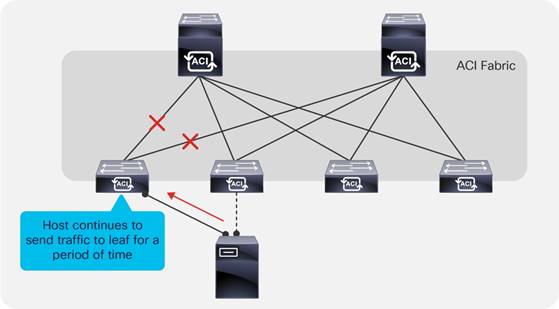
The port tracking feature detects a loss of fabric connectivity on a leaf switch and brings down the host-facing ports. This allows the host to fail over to the second link, as shown in Figure 34.

Except for very specific server deployments, servers should be dual-homed, and port tracking should always be enabled. Port tracking is located under System > System Settings > Port Tracking.
When the number of operational fabric ports comes back up, the downlink ports will be brought back up if the number of uplink ports is greater than the configured threshold. Cisco ACI doesn’t activate the downlink ports immediately once these conditions are met, because even if the fabric uplinks are up, the protocols that are necessary for forwarding to work may not be yet converged. To avoid blackholing traffic from the servers to the spine switch, the Cisco ACI leaf switch delays the downlink ports bring up for the configured delay time.
The delay timer unit of measurement is in seconds, and the default value is 120 seconds. The timer applies to all ports, including vPC (more on this in the next section).
Ports configured as part of a vPC operate as if port tracking was enabled without the need for any extra configuration. vPC fabric port tracking, as with port tracking, uses the ISIS adjacency information in addition to the physical link status to bring up or down the vPC front panel ports. Also, when fabric links are restored, Cisco ACI delays the vPC ports bring up to avoid blackholing traffic.
Interaction with Cisco APIC Ports
By default, port tracking doesn’t bring down Cisco APIC ports, but from Cisco ACI 5.0(1) this option is configurable. The option is called "Include APIC ports." If this option is disabled, port tracking brings down all downlinks except Cisco APIC ports. If this option is enabled, Cisco ACI also brings down ports connected to Cisco APIC ports.
Loop Mitigation Features Overview
Cisco ACI is a routed fabric, hence there is intrinsically no possibility of a loop at the fabric infrastructure level. On the other hand, you can build bridge domains on top of the routed fabric, and you could potentially introduce loops by merging these domains with external cabling or switching. You can also to have a loop on the outside networks connected to the Cisco ACI fabric, and these loops could also have an impact on the Cisco ACI fabric.
Examples of loops include a cable connecting two front panel ports that are both on the same bridge domain (but they could very well be on different EPGs) or a misconfigured blade switch connected to Cisco ACI leaf switches without spanning tree and with a vPC not correctly configured.
In both cases, what happens is that a multidestination frame would be replicated infinite times, causing both a surge in the amount of traffic on all the links that transport the bridge domain traffic and MAC address flapping between the ports where the source MAC of the frame really comes from and the ports where this traffic is replicated (the ports causing the loop). Features such as storm control address the problem of the congestion on the links, and features such as endpoint loop protection or rogue endpoint control address the problem of the MAC address moving too many times.
The impact of a loop, even a temporary one, can be vary greatly depending on which servers on the bridge domain will send a broadcast or a multidestination frame exactly while the conditions for the loop are present. It is very possible that a temporary loop is present, but doesn’t cause MAC movements nor a surge in the amount of multidestination traffic.
The usual design best practices for mitigating the effects of loops apply to Cisco ACI as well. For instance, when Cisco ACI takes a loop mitigation action for a Layer 2 domain, this applies potentially to the entire bridge domain (depending on the feature that you choose and depending also on the endpoint movement). Hence, it is a good practice to use segmentation in Cisco ACI as well, which means considering bridge domain separation as a way to reduce the impact of potential loops.
This section illustrates the features that can be configured at the fabric access policy level to reduce the chance for loops or reduce the impact of loops on the Cisco ACI fabric.
The following features help prevent loops: the Mis-Cabling Protocol (MCP), forwarding BPDUs in the Cisco ACI fabric in the bridge domain, or using BPDU Guard on ports that are not meant to be connected to an external Layer 2 network. Use BPDU guard only where applicable, which is where servers are directly connected to ACI leaf switches, because in the case of ports connected to an external Layer 2 network, forwarding BPDUs may be instead the right way to keep the topology loop free.
Other features help minimize the impact of loops on the fabric itself: storm control, control plane policing per interface per protocol (CoPP), endpoint move dampening, endpoint loop protection, and rogue endpoint control.
LLDP for Mis-Cabling Protection
Cisco ACI has a built-in check for incorrect wiring, such as a cable connected between two ports of the same leaf switch or different leaf switches. This is done by using the LLDP protocol. The LLDP protocol by itself is not designed to prevent loops, and it is slow in that it sends an LLDP packet every 30 seconds by default, but it can be quite effective at detecting mis-cabling because at port link up Cisco ACI sends an LLDP frame, which, normally leads to detecting mis-cabling within less than one second. This is possible because there are specific LLDP TLV fields that Cisco ACI uses to convey the information about the role of the device that is sending the LLDP packet, and if a leaf switch sees that the neighbor is also a leaf switch, it disables the port.
When the port is in the disabled state, this port is only able to send/receive LLDP traffic and DHCP traffic. No data traffic can be forwarded. This helps avoiding loops that are caused by incorrect wiring.
Mis-Cabling Protocol (MCP) Overview
Unlike traditional networks, the Cisco ACI fabric does not participate in the Spanning Tree Protocol and does not generate BPDUs. BPDUs are, instead, transparently forwarded through the fabric between ports mapped to the same EPG on the same VLAN. Therefore, Cisco ACI relies to a certain degree on the loop prevention capabilities of external devices.
Some scenarios, such as the accidental cabling of two leaf switch ports together, are handled directly using LLDP in the fabric. However, there are some situations where an additional level of protection is necessary. In those cases, enabling MCP can help.
MCP, if enabled, provides additional protection against misconfigurations that would otherwise result in loops. MCP is a per physical port feature, and not a per bridge domain feature. With MCP enabled, Cisco ACI disables the port (s) where a loop is occurring while keeping one port up: if a loop occurs it means that there are multiple Layer 2 paths for the same Layer 2 network, hence only one front panel port needs to stay up, the others can be disabled.
If the Spanning Tree Protocol is running on the external switching infrastructure, under normal conditions MCP does not need to disable any link. Should Spanning Tree Protocol stop working on the external switches, MCP intervenes to prevent a loop.
Even if MCP detects loops per VLAN, if MCP is configured to disable the link and if a loop is detected in any of the VLANs present on a physical link, MCP then disables the entire link.
Spanning Tree Protocol provides better granularity such that if a looped topology is present, external switches running Spanning Tree Protocol provide more granular loop-prevention. MCP is useful if Spanning Tree Protocol stops working or if Spanning Tree is simply not used when connecting external switches to Cisco ACI.
Link Aggregation Control Protocol (LACP) Suspend Individual Ports
When connecting a Cisco ACI leaf switch using a port channel to other switching devices such as a separate physical switch or a blade switch, we recommend that you ensure that the LACP suspend individual port is enabled. This configuration may be different than the recommended configuration when connecting Cisco ACI leaf switch ports directly to a host. This section explains why.
It is outside the scope of this document to describe LACP. For information about LACP, refer to this document: https://www.cisco.com/c/en/us/td/docs/ios/12_2sb/feature/guide/sbcelacp.html
The states of a port configured to run the Link Aggregation Control Protocol can be one of these:
● Bundled, when the port is bundled with the other ports
● Individual, when LACP is not running on the partner port and the LACP Suspend Individual Port option is not selected
● Suspended when LACP is not running on the partner port and the LACP Suspend Individual Port option is selected
● Standby
● Down
The LACP Suspend Individual Port option (Fabric > Access Policies > Policies > Interface > Port Channel > Port Channel Policy) lets you choose between these two outcomes for the scenario where the peer device doesn’t send any LACP packets to a leaf switch port configured for LACP:
● If the LACP "Suspend Individual Port" Control option is selected: the port is put into the Suspended state. This potentially can prevent loops, because an individual port could be part of the same Layer 2 domain as the other ports that are configured for port channeling. This option is mostly beneficial if the Cisco ACI port channel is connected to an external switch.
● If the LACP "Suspend Individual Port" Control option is not selected: the port is kept in the Individual state. This means that it operates the same as any other switch port. This option can be useful when the port channel is connected to a server, because if the server performs a PXE boot, the server is not able to negotiate the port channel at the very beginning of the boot up phase. In addition, a server typically won’t switch traffic across the NIC teaming interfaces of the port channel, hence keeping the port in the Individual state while waiting for the server bootup, which should not introduce any loops.
When loop conditions are present due to miscabling or a wrong configured switch connected to Cisco ACI leaf switches, multidestination frames from servers can be replicated infinite times, creating a significant amount of multidestination traffic that could congest the links including the uplinks from the leaf switches to the spine switches as well as the servers that are in the same bridge domain. The purpose of storm control is not to protect the Cisco ACI leaf switches’ CPU. The CPUs are protected by CoPP.
Examples of server-generated frames that can be replicated in presence of a loop are for instance BOOTP frames, ARP frames, and so on. Storm control applies both to regular dataplane traffic destined to a broadcast address or to an unknown unicast address, as well as to "control plane" traffic, such as ARP, DHCP, and ND.
If a bridge domain is set to use hardware proxy for unknown unicast traffic, the traffic storm control policy will apply to broadcast and multicast traffic. However, if the bridge domain is set to flood unknown unicast traffic, traffic storm control will apply to broadcast, multicast, and unknown unicast traffic.
With traffic storm control, Cisco ACI monitors the levels of the incoming broadcast, multicast, and unicast traffic over a fixed time interval. During this interval, the traffic level, which is a percentage of the total available bandwidth of the port, is compared with the traffic storm control level that administrator configured. When the ingress traffic reaches the traffic storm control level that is configured on the port, traffic storm control drops the traffic until the interval ends.
Starting with Cisco ACI 4.2(6) and 5.1(3), storm control has been improved to include certain control plane protocols that were previously only rate limited by CoPP. Specifically, starting in these releases, storm control works on all control plane protocols and with flood in encapsulation.
Traffic storm control on the Cisco ACI fabric is configured by opening the Fabric > Access Policies menu and choosing Interface Policies.
Traffic storm control takes two values as configuration input:
● Rate: Defines the rate level against which traffic will be compared during a 1-second interval. The rate can be defined as a percentage or as the number of packets per second. The policer has a "minimum" rate enforcement of 1 Mbps. This means that any traffic rate that is below this number cannot be rate limited by storm control. 1 Mbps with 256 bytes packets is (1000000/(256*8)) = 488 packets. If traffic exceeds the "rate" (see previous bullet), it is rate limited, but if during previous intervals the traffic was less than the specified "rate", tokens are accumulated that can be used by a burst. Traffic rate above this rate can be allowed if there is an accumulation of tokens.
● Max burst rate: In a given interval, Cisco ACI may allow a traffic rate higher than the defined "rate". The "max burst rate" specifies the absolute maximum traffic rate after which traffic storm control begins to drop traffic. This rate can be defined as a percentage or the number of packets per second.
Interface-level Control Plane Policing (CoPP)
Control Plane Policing (CoPP) was introduced in Cisco ACI 3.1. With this feature, control traffic is rate-limited first by the interface-level policer before it hits the aggregated CoPP policer. This prevents traffic from one interface from flooding the aggregate COPP policer, and as a result ensures that control traffic from other interfaces can reach the CPU in case of loops or Distributed Denial of Service (DDoS) attacks from the configured interface.
The per-interface-per-protocol policer supports the following protocols: Address Resolution Protocol (ARP), Internet Control Message Protocol (ICMP), Cisco Discovery Protocol (CDP), Link Layer Discovery Protocol (LLDP), Link Aggregation Control Protocol (LACP), Border Gateway Protocol (BGP), Spanning Tree Protocol, Bidirectional Forwarding Detection (BFD), and Open Shortest Path First (OSPF). It requires Cisco Nexus 9300-EX or later switches.
Spanning Tree Protocol Considerations
The Cisco ACI fabric does not run Spanning Tree Protocol natively, but it can forward BPDUs within the EPGs.
The flooding scope for BPDUs is different from the flooding scope for data traffic. The unknown unicast traffic and broadcast traffic are flooded within the bridge domain. Spanning tree protocol BPDUs are flooded within a specific VLAN encapsulation (also known as FD_VLAN), and in many cases, though not necessarily, an EPG corresponds to a VLAN. This topic is covered in further detail in the "Bridge Domain Design Considerations" and "Connecting EPGs to External Switches" section.
Figure 35 shows an example in which external switches connect to the fabric.
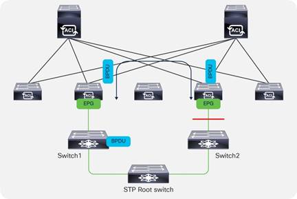
Cisco ACI handles the BPDU traffic using the MCP process, but this handling works even if MCP is not enabled. Cisco ACI parses the BPDUs in order to verify if the TCN bit is set and in case the MST protocol is used, Cisco ACI also reads the region configuration. In fact, in order to verify Cisco ACI’s handling of the spanning tree traffic you have to use the command: show mcp internal info vlan <vlan number>.
BPDU traffic received from a leaf switch is classified by Cisco ACI as belonging to the control plane qos-group, and this classification is preserved across pods. If forwarding BPDUs across pods, make sure that either dot1p preserve or tenant "infra" CoS translation is configured.
It is good practice to configure ports that connect to physical servers with BPDU Guard so that if an external switch is connected instead, the port is error-disabled.
It can also be useful to configure BPDU Guard on virtual ports (in the VMM domain).
The loop detection performed by MCP consists of the following key mechanisms:
● Cisco ACI leaf switch ports generate MCP frames at the frequency defined in the configuration. When everything is normal, Cisco ACI doesn’t receive MCP frames. If Cisco ACI receives MCP frames, it can be the symptom of a loop.
● In a port channel, MCP frames are sent only on the first port that became operational in the port channel.
● With vPCs, Cisco ACI sends MCP frames from both vPC peers.
● If a Cisco ACI leaf switch port receives an MCP frame generated by the very same fabric, this is a symptom of a loop. Hence, after receiving N MCP frames (with N configurable), Cisco ACI compares the MCP priority to determine which port will be shut down.
● To determine which port stays up and which one is shut down, Cisco ACI compares the fabric ID, the leaf switch ID, the vPC information, and the port ID. The lower number has the higher priority. If a loop is between the ports of the same leaf switch, then vPC has higher priority than port channels, and port channels have higher priority than physical ports.
● The time that it takes for MCP to shut down a port is: (tx interval * loop detection multiplier) + (tx_interval/2). The loop detect multiplication factor is the number of continuous packets that a Cisco ACI leaf switch port must receive before declaring a loop.
● If the port is blocked (error-disabled) [MCP_BLOCKED state], the port doesn’t send/receive any user traffic. However, STP/MCP packets are still allowed.
● Admin shut/no-shut clears the port state to the forwarding state, but you can also configure an err-disable recovery policy for MCP to bring up the port again with a default time of 300 seconds.
We recommend that you enable MCP on ports facing external switches or similar devices where there is a possibility that they may introduce loops. Make sure to enable MCP on leaf switch ports while staying within the scalability limit based on the verified scalability guide.
The MCP policy group level default configuration sets MCP as enabled on the interface, but MCP does not work until and unless MCP is configured as globally enabled. Hence, even if the Fabric > Access Policies > Policies > Interface > MCP Interface > MCP default configuration is set as enabled and thus enabled on all the interfaces that use the default, you need to enable a global MCP configuration for MCP to work.
This can be done using the Global Policies section of the Fabric > Access Policies tab, as shown in Figure 36.
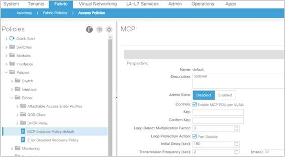
The configuration of MCP requires entering a key to uniquely identify the fabric.
The initial delay should be set in case the Cisco ACI leaf switches connect to an external network that runs STP to give time to STP to converge. If instead it is assumed that there is no STP configuration on the external network, then it is reasonable to set the initial delay to 0 for MCP to detect loops more quickly.
With a default transmission frequency of 2 seconds and a loop detection multiplier of 3, it takes ~7s for MCP to detect a loop.
In the presence of short loops due to cabling of external switches that do not run STP, it may be beneficial that MCP detects loops faster than 7s. This can be achieved by setting a frequency of a few hundred milliseconds with a loop detection multiplier of 3 so that the time to detect a loop becomes: ~350-400ms.
Because aggressive timers increase the utilization of the control plane, before you do this you should see the scalability guide to ensure that your configuration is within the scale limits and test the configuration in your environment.
If you want to lower the detection time to prevent loops during cabling, the best approach is to use MCP strict instead of aggressive timers.
Prior to Cisco ACI release 2.0(2f), MCP detected loops at the link level by sending MCP PDUs untagged. Software release 2.0(2f) added support for per-VLAN MCP. With this improvement, Cisco ACI sends MCP PDUs tagged with the VLAN ID specified in the EPG for a given link. Therefore, now MCP can be used to detect loops in non-native VLANs.
Even if MCP can detect loops per-VLAN, if MCP is configured to disable the link, and if a loop is detected in any of the VLANs present on a physical link, MCP then disables the entire link.
Prior to Cisco ACI release 6.0(2), per-VLAN MCP supported a maximum of 256 VLANs per link, which means that if there are more than 256 VLANs on a given link, MCP generates PDUs on the first 256. Starting with Cisco ACI 6.0(2), you can configure MCP to work on up to 2000 VLANs on the same port.
Per-VLAN MCP can be CPU intensive depending on how many VLANs are used and on how many ports they are used on. This limit is documented in terms of Port, VLANs (or in short P, V): which is ∑(#VLANs(Pi)) with i = 1 to #Logical Ports, where a logical port is a regular port or a port channel. To be more precise, considering that MCP sends MCP on the first 256 VLANs, the formula is: ∑ [min(256, #VLANs(Pi))] with i = 1 to #Logical Ports.
This limit is measured per leaf switch, and you can verify how many P, V are used on a given leaf switch by using the following command: show mcp internal info interface all | grep "Number of VLANS in MCP packets are sent" and adding the output from all the lines. The total must be less than 2000 or 12000 depending on the software release of the Cisco ACI fabric.
Starting from Cisco ACI 6.0(2), you can selectively enable per-VLAN MCP on a per-port basis, which gives more control to keep MCP within the scalability limits.
These limits can be found in the Verified Scalability Guide for Cisco APIC and Cisco Nexus 9000 Series ACI-Mode Switches document.
As a result of the enhancements introduced in Cisco ACI 6.0(2), there are two configurations in Cisco APIC that control per-VLAN MCP:
● A global configuration: Fabric > Access Policies > Policies > Global > MCP Instance Global Policy. By default, per-VLAN MCP is set to disabled.
● An interface configuration: Fabric > Access Policies > Policies > Interface > MCP Interface. By default, per-VLAN MCP is set to enabled.
Cisco ACI sends MCP PDUs per-VLAN if you enabled both options. Given that the MCP Interface option by default is enabled, if you choose per-VLAN MCP in the MCP Instance Global Policy, Cisco ACI leaf switches send MCP per VLAN on all ports. This is also true in Cisco ACI releases prior to 6.0(2)).
Given that per-VLAN MCP at scale can be CPU intensive, the preferred configuration option for greenfield deployments starting from Cisco ACI 6.0(2) is to disable per-VLAN MCP on the default MCP interface policy and to enable per-VLAN MCP selectively on the interfaces where you needed it. This best practice ensures that even if you enable per-VLAN MCP globally, Cisco ACI does not send MCP on all VLANs on all ports.
MCP loop detection takes about 350 milliseconds with an aggressive timer configuration or up to 7 seconds with a default configuration. During this time, if there is a loop, rogue endpoint control can declare several endpoints as rogue, which could potentially result in a disruption in the bridge domain.
Cisco ACI 5.2(4) introduced an enhancement that combines the benefits of MCP with aggressive timers and the scale benefits of MCP with normal timers.
MCP in strict mode is a mode with which Cisco ACI moves a port to the forwarding state only after the MCP loop detection completes and no loops are detected. The loop detection is performed at link up with aggressive timers.
MCP strict is configured per interface. The timers allow you to define the speed of the detection performed by MCP at link up: TX frequency for the initial transmission frequency and the grace period, which is the time during which MCP monitors the link for loops before putting the port into forwarding mode. With 500 milliseconds of transmission frequency and a grace period of 3,000 milliseconds, MCP monitors the link for 3 seconds for loops by sending frames at a 500-millisecond interval before putting the link into forwarding mode. Subsequently, MCP monitors the link with the default MCP timers.
If MCP is configured per-VLAN, MCP strict verifies the link for loops on only the first 256 VLANs defined on a link.
Endpoint Move Dampening, Endpoint Loop Protection, and Rogue Endpoint Control
To understand how Endpoint Move Dampening, Endpoint Loop Protection, and Rogue Endpoint Control work, it is important to first clarify what an endpoint is from a Cisco ACI perspective and what an endpoint move means. The endpoint can be:
● A MAC address
● A MAC address with a single IP address
● A MAC address with multiple IP addresses
An endpoint move can be one of the following events:
● A MAC moving between interfaces or between leaf switches. If a MAC address moves, all IP addresses associated with the MAC address move too.
● An IP address moving from a MAC address to another.
Cisco ACI has three features that look similar in that they help when an endpoint (a MAC address primarily) is moving too often between ports:
● Endpoint move dampening is configured from the bridge domain under the Endpoint Retention Policy and is configured as "Move Frequency." The frequency expresses the number of aggregate moves of endpoints in the bridge domain. When the frequency is exceeded, Cisco ACI stops learning on this bridge domain. The amount of time that learning is disabled is configurable by setting the "Hold Interval" in the endpoint retention policy in the bridge domain configuration and by default is 5 minutes.
● The endpoint loop protection is a feature configured at the global level (System Settings > Endpoint Controls). The feature is turned on for all bridge domains, and it counts the move frequency of individual MAC addresses. When too many moves are detected, you can choose whether Cisco ACI should suspend one of the links that cause the loop (you cannot control which one), or disable learning on the bridge domain. The amount of time that learning is disabled is configurable by setting the "Hold Interval" in the endpoint retention policy in the bridge domain configuration and by default is 5 minutes.
● Rogue endpoint control is similar to the endpoint loop protection feature in that it is a global setting (System Settings > Endpoint Controls) and it counts the move frequency of individual endpoints. Different from endpoint loop protection, rogue endpoint control counts the frequency of MAC address moves, but also the frequency of IP address-only moves. When a "loop" is detected, Cisco ACI just quarantines the endpoint; that is, Cisco ACI freezes the endpoint as belonging to a VLAN on a port and disables learning for this endpoint. The amount of time that the endpoints are "quarantined" is configurable with the "Hold interval" parameter in the System Settings > Endpoint Controls > Rogue EP Control. With the Cisco ACI release 5.2(2) and earlier, the hold timer is 30 minutes. Starting with Cisco ACI 5.2(3), the hold timer can be set to a minimum value of 5 minutes.
While these features do not prevent loops, if a loop occurs and it causes MAC flapping between ports, these features help minimize the impact of the loop. For example, by using rogue endpoint control, if a loop occurs in a given bridge domain, the result of the loop will be that the endpoints that were flapping within a given bridge domain are quarantined, while the other bridge domains are able to continue functioning normally.
Note: The L3Out SVI in Cisco ACI is an external bridge domain with an SVI interface. As with all bridge domains, the external bridge domain is configured for endpoint move dampening with parameters that cannot be configured. If endpoint controls, such as rogue endpoint control, are configured, they also apply to the L3Out SVI external bridge domain.
Endpoint move dampening counts the aggregate moves of endpoints. Hence, if you have a single link failover with a number of endpoints whose count exceeds the configured "move frequency" (the default is 256 "moves"), endpoint move dampening may also disable learning. When the failover is the result of the active link (or path) going down, this is not a problem because the link going down flushes the endpoint table of the previously active path. If instead the new link takes over without the previously active one going down, endpoint dampening will disable the learning after the configurable threshold (256 endpoints) is exceeded. If you use endpoint move dampening you should tune the move frequency to match the highest number of active endpoints associated with a single path (link, port channel, or vPC). This scenario doesn’t require special tuning for endpoint loop protection and rogue endpoint control because these two features count moves in a different way.
When there are too many moves, endpoint move dampening disables learning in the bridge domain and flushes the endpoint that was moving too frequently. At the time of this writing, there is a bug that may result in other endpoints on the same bridge domain to be flushed as a result of endpoints moving too fast.
The duration for which a bridge domain will be in the learn disable state depends on the hold interval specified in the retention policy. The default value is 300 seconds,
If you are concerned with endpoint move dampening disabling learning on a bridge domain unnecessarily, you can configure the move frequency to be 1024 moves, which is the maximum value that you should use even if the GUI may allow you to enter higher values.
Endpoint move dampening is configured from Tenant > Tenant Name > Networking > Bridge Domains > BD name > Policy > General > Endpoint Retention Policy.
Figure 37 illustrates how endpoint loop protection and rogue endpoint control help with either misconfigured servers or with loops. In the figure, an external Layer 2 network is connected to a Cisco ACI fabric, and due to some misconfiguration, traffic from H1 (such as an ARP packet) is looped and in this theoretical example, it moves ten times between leaf 1 and leaf 4 (in a real case scenario it would be much more). Endpoint loop protection and rogue endpoint control would then respectively disable learning on BD1 or for the MAC address of H1. If there are four endpoints that have generated a multidestination frame during the loop, Cisco ACI leaf switches use a deduplication feature that lets the Cisco ACI count the move of individual endpoints (see the right-hand side of the figure) and detect a loop regardless of whether a single endpoint is moving too often (which most likely is not a loop, but maybe an incorrect NIC-teaming configuration) or multiple endpoints are moving too often (as happens with loops).

Endpoint loop protection takes action if the Cisco ACI fabric detects an endpoint moving more than a specified number of times during a given time interval. Endpoint loop protection can take one of two actions if the number of endpoint moves exceeds the configured threshold:
● It disables endpoint learning within the bridge domain.
● It disables the port to which the endpoint is connected.
Endpoint loop protection is configured from System > System Settings > Endpoint Controls > EP Loop Protection.
The default parameters for endpoint loop protection are as follows:
● Loop detection interval: 60
● Loop detection multiplication factor: 4
These parameters state that if an endpoint moves more than four times within a 60-second period, the endpoint loop-protection feature will take the specified action (for example, disabling the port). The recommended configuration is to set bridge domain learn disable as the action.
If the action taken during an endpoint loop-protection event is to disable the port, the administrator may wish to configure automatic error disabled recovery; in other words, the Cisco ACI fabric will bring the disabled port back up after a specified period of time. This option is configured by choosing Fabric > Access Policies > Global Policies and choosing the Frequent EP Moves option.
If endpoint loop protection detects a loop, it raises the fault F3261 "Learning is disabled on BD <BD name> - Loop is detected for MAC <MAC address> on node with id <node id> with name <leaf name>".
If the action taken is to disable bridge domain learning, the duration of this action is configurable by changing the "Hold interval" under the endpoint retention policy for the bridge domain. This same policy is used for Endpoint Move dampening.
The configuration of endpoint loop protection is global, but you define the control for how long learning is disabled on a bridge domain in the endpoint retention policy of the bridge domain at Tenant > Tenant Name > Networking > Bridge Domains > BD name > Policy > General > Endpoint Retention Policy.
Rogue endpoint control is a feature introduced in Cisco ACI 3.2 that can help in case there are MAC or IP addresses that are moving too often between ports. With the other loop protection features, Cisco ACI takes the action of disabling learning on an entire bridge domain or it err-disables a port.
With rogue endpoint control, only the misbehaving endpoint (MAC/IP address) is quarantined, which means that Cisco ACI keeps its TEP and port fixed for a certain amount of time when learning is disabled for this endpoint. The feature also raises a fault F3013 to allow easy identification of the problematic endpoint.
Note: Rogue endpoint control is configurable in Cisco ACI 3.1, but the feature was released only in Cisco ACI 3.2. Because of this, if you downgrade from Cisco ACI 3.2 to a previous release, you must disable this feature. If you upgrade from a 4.0 or 4.1 release to a 4.2 release, you should disable rogue endpoint control before the upgrade and re-enable it after.
The default parameters for rogue endpoint control are as:
● Rogue endpoint detection interval: 60
● Rogue endpoint detection multiplication factor: 6
In the presence of a loop or simply when an endpoint moves more than 6 times in a 60-second interval, when rogue endpoint control is configured, Cisco ACI quarantines only the endpoints that move too frequently. In case of loops, these are the endpoints that may have sent a broadcast frame during the loop. The other endpoints do not experience any disruption unless their traffic path is through the endpoints that were quarantined. Each leaf switch independently evaluates to which port the endpoint belongs. Hence, the endpoint may be quarantined on a local port or on a tunnel port. Cisco ACI does not have a way to know which is the "right" port, so statistically it is possible that an endpoint may be quarantined on the "wrong" port.
After endpoints are quarantined, Cisco ACI disables dataplane learning for these endpoints for the amount of time specified in the hold interval in the configuration, which by default is 1800 seconds (30 minutes), but starting from Cisco ACI 5.2(3) it can be set to 5 minutes.
If it is necessary to re-establish learning for endpoints that have been quarantined, the administrator can check on which leaf switches Cisco ACI raised fault F3013 by using the command admin@apic1:~> moquery -c faultInst -f 'fault.Inst.code=="F3013". The administrator can clear the rogue endpoints on the leaf switches by using the CLI (clear system internal epm endpoint rogue) or using the GUI (Fabric Inventory > POD > Leaf, right click Clear Rogue Endpoints).
If rogue endpoint control is enabled, loop detection and endpoint dampening (bridge domain move frequency) will not take effect. The feature works within a site.
Rogue Endpoint Control Exceptions
Rogue endpoint control also helps in case of incorrect configurations on servers, which may cause endpoint flapping. In such a case, Cisco ACI does not disable the server ports, as endpoint loop protection may do., Instead, Cisco ACI stops the learning for the endpoint that is moving too often and provides a fault with the IP address of the endpoint that is moving too often so that the administrator can verify its configuration.
For instance, if servers are doing active/active TLB teaming or if there are active/active clusters, the IP address may be moving too often between ports. Rogue Endpoint Control would then quarantine these IP addresses and raise a fault. To fix this problem, you could either change teaming on the servers or you may disable IP dataplane learning.
For more information, see the "When and how to disable IP dataplane learning" section.
With IP dataplane learning is disabled Cisco ACI, will learn the endpoint IP address from ARP, which will fix the forwarding issue, and rogue endpoint control will not raise additional faults after the configuration change. Rogue endpoint control still protects from scenarios where the MAC address moves too frequently or when the IP address moves too frequently because of continuous ARPs with changing IP address to MAC address information.
There are scenarios where IP addresses or MAC addresses may flap temporarily. This may be due to the failover of a device, such as a Layer 4 to Layer 7 services device (such as a firewall). In these cases, rogue endpoint control may quarantine the device MAC address or IP address, which could cause disruption to the traffic that pass through the device.
If the issue is caused by an IP address that is temporarily active on both devices while the MAC address does not move, you can disable IP dataplane learning to address this problem.
If the issue instead is caused by a MAC address that is simultaneously used by both devices during the failover, starting from Cisco ACI 5.2(3), you can exclude the MAC address from rogue endpoint control.
This is possible If the bridge domain is a Layer 2 bridge domain (that is, the bridge domain does not do routing). You can find the configuration at Tenant > Networking > BD > Advanced/Troubleshooting Tab > Rogue/COOP Dampening List. A maximum of 100 MAC addresses can be excluded across the entire fabric in Cisco ACI 5.2(3) and 500 from Cisco ACI 5.2(4).
Summary Best Practices for Layer 2 Loop Mitigation
In summary, to reduce the chance of loops and their impact on the fabric, you should do the following:
● Make sure that port channels use LACP and that the option LACP Suspend Individual ports is enabled unless the port channel is connected to a server. In such a case, you should evaluate the pros/cons of the LACP suspend individual feature based on the type of server.
● Enable either loop endpoint protection or global rogue endpoint control (with a preference for rogue endpoint control) after understanding the pros and cons of each option to mitigate the impact of loops and incorrect NIC teaming configurations on the Cisco ACI fabric. Make sure the operations team understands how to check rogue endpoint faults and can clear rogue endpoints manually if the loop is resolved. Neither endpoint loop protection nor rogue endpoint control can stop a Layer 2 loop, but they provide mitigation of the impact of a loop on the COOP control plane by quarantining the endpoints.
We recommend that you enable MCP selectively on the ports where MCP is most useful, such as the ports connecting to external switches or similar devices if there is a possibility that they may introduce loops. The default MCP protocol interface policy that gets applied to the interface policy group normally has MCP enabled. Therefore, if you enabled MCP globally, MCP will be enabled on the interface. To disable MCP on the interfaces that do not need it, you should create a new MCP protocol interface policy with MCP disabled and apply it to the interface policy group for the interfaces where MCP is not needed.
● Enable MCP in the fabric access global policies by entering a key to identify the fabric and by changing the administrative state to enabled. Configure the Initial delay depending on the external Layer 2 network. We recommend a value of 0 if the external network doesn’t run Spanning Tree. Otherwise, you should enter a value that gives time for Spanning Tree to converge.
● Enable per-VLAN MCP with caution. Starting with ACI 6.0(2) it is possible to enable per-VLAN MCP selectively on specific interfaces only. See the Verified Scalability Guide to make sure that the P, V scale is within the limits.
● Consider the use of MCP strict instead of aggressive timers
● Configure Cisco ACI so that the BPDUs of the external network are forwarded by Cisco ACI by configuring EPGs with consistent VLAN mappings to ports connected to the same Layer 2 network.
● Configure spanning tree BPDU guard on server ports.
● You can also configure traffic storm control as an additional mitigation in case of loops.
● Most networking devices today support both LLDP and CDP, so make sure the Cisco ACI leaf switch interfaces are configured with the protocol that matches the capabilities of connected network devices.
This section summarizes some of the "Global" settings that are considered best practices.
The following settings apply to all tenants:
● Configure two BGP route reflectors from the available spine switches. This configuration is located at System Settings > BGP Route Reflector.
● The "Disable remote endpoint learning" configuration in System > System Settings should be kept unchecked with second generation Cisco ACI leaf switches. This option is useful to prevent stale entries in the remote table of the border leaf switches only with first generation Cisco ACI leaf switches.
● Enable "Enforce Subnet Check": This configuration ensures that Cisco ACI leaf switches learn only endpoints whose IP address belongs to the bridge domain subnet to which the port is associated through the EPG. It also ensures that leaf switches learn the IP address of remote endpoints only if the IP address belongs to the VRF with which they are associated.
● Enable IP address aging: This configuration is useful to age individual IP addresses when there are many IP addresses that may be associated with the same MAC address, such as in the case of a device that does NAT and is connected to the Cisco ACI.
● Enable "Enforce Domain validation" and "Enforce EPG VLAN Validation": This option ensures that the fabric access domain configuration and the EPG configurations are correct in terms of VLANs, thus preventing configuration mistakes.
● At the time of this writing, if you plan to deploy Kubernetes (K8s) or Red Hat OpenShift Container Platform, you should deselect OpFlex Client Authentication.
● Verify the MCP scalability limits in the verified scalability guide.
● For a greenfield deployment with Cisco ACI release 6.0(2) or later, change the default MCP Interface policy to disable per-VLAN MCP, then you can enable MCP with the MCP Instance Global Policy (including the per-VLAN option if you plan to selectively enable per-VLAN MCP on specific interfaces).
● For Cisco ACI releases earlier than 6.0(2), decide on which ports MCP should be enabled or disabled, then you can enable MCP with the MCP Instance Global Policy (including the per-VLAN option only if the per-leaf switch scale is compatible with the verified scalability limits).
● Enable either endpoint loop protection or rogue endpoint detection: These features limit the impact of a loop on the fabric by either disabling dataplane learning on a bridge domain where there is a loop or by quarantining the endpoints whose MAC address or IP address moves too often between ports.
● Configure a lower cost for IS-IS redistributed routes than the default value of 63.
Note: For more information about disabling remote endpoint learning and enabling IP address aging, see the "Cisco ACI endpoint management" section.
Figure 38 shows how to configure the global system settings.
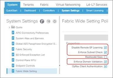
This option causes a Cisco ACI fabric to learn the endpoint MAC address and IP address of the untagged traffic arriving on the Cisco ACI fabric. By default, such traffic is dropped if there is an EPG deployed on the leaf switch interface, hence the endpoint MAC address or IP address are not learned/discovered.
By enabling this feature, Cisco ACI discovers the endpoints and shows them under the System Settings > Global Endpoints view. You can then utilize the endpoint MAC address and IP address information to create the matching criteria for uSeg EPG or ESGs instead of relying on VLAN ID for EPG classification.
This feature is disabled by default and is configurable at the following GUI location: System > System Settings > Global Endpoints.
Note: This option was introduced as beta feature in Cisco ACI release 4.2(4). As of Cisco ACI release 5.1(3), it’s still beta.
The VLAN ID of the configuration System Settings > Global Endpoints > End Point Listen Encap must not belong to any VLAN pool that is used for EPG classification. Endpoints learned by this feature can’t talk to other endpoints in the fabric until proper EPG or ESG classification for the endpoint is performed.
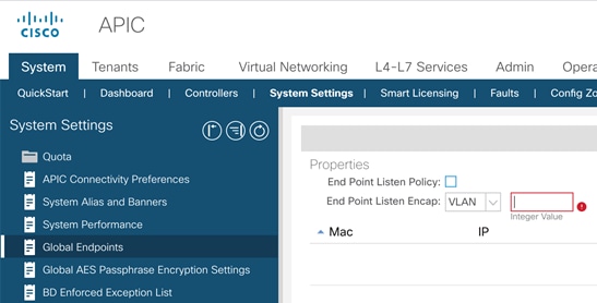
The Cisco ACI fabric uses VXLAN-based overlays to provide the abstraction necessary to share the same infrastructure across multiple independent forwarding and management domains, called tenants. Figure 40 illustrates the concept.
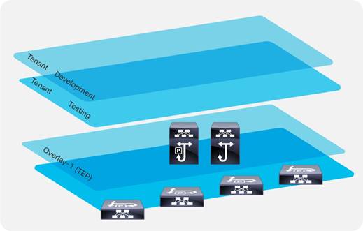
A tenant is a collection of configurations that belong to an entity. Tenants primarily provide a management domain function, such as the development environment in Figure 40, that keeps the management of those configurations separate from those contained within other tenants.
By using VRF instances and bridge domains within the tenant, the configuration also provides a dataplane isolation function. Figure 41 illustrates the relationship among the building blocks of a tenant.
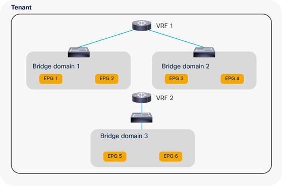
In a traditional network infrastructure, the configuration steps consist of the following:
1. Define a number of VLANs at the access and aggregation layers.
2. Configure access ports to assign server ports to VLANs.
3. Define a VRF instance at the aggregation-layer switches.
4. Define an SVI for each VLAN and map these to a VRF instance.
5. Define Hot Standby Router Protocol (HSRP) parameters for each SVI.
6. Create and apply Access Control Lists (ACLs) to control traffic between server VLANs and from server VLANs to the core.
A similar configuration in Cisco ACI requires the following steps:
1. Create a tenant and a VRF instance.
2. Define one or more bridge domains, configured either for traditional flooding or for using the optimized configuration available in Cisco ACI.
3. Create EPGs for each server security zone and map them to ports and VLANs.
4. Configure the default gateway (known as a subnet in Cisco ACI) as part of the bridge domain or the EPG.
5. Create contracts.
6. Configure the relationship between EPGs and contracts.
Network-centric and Application-centric Designs (and EPGs Compared with ESGs)
This section clarifies two commonly used terms to define and categorize how administrators configure Cisco ACI tenants.
If you need to implement a simple topology, you can create one or more bridge domains and EPGs and use the mapping of 1 bridge domain = 1 EPG = 1 VLAN. This approach is commonly referred to as a network-centric design.
You can implement a Layer 2 network-centric design where Cisco ACI provides only bridging or a Layer 3 network-centric design where Cisco ACI is used also for routing and to provide the default gateway for the servers.
If you want to create a more complex topology with more security zones, you can divide the bridge domain with more EPGs or classify traffic into endpoint security groups (ESG) and use contracts to define ACL filtering between EPGs or ESGs. This design approach is often referred to as an application-centric design.
Note You can configure contracts between EPGs or between ESGs but not between an EPG and an ESG. You can however define a contract between an External EPG and an ESG.
These are just commonly used terms to refer to a way of configuring Cisco ACI tenants. There is no restriction about having to use only one approach or the other. A single tenant may have bridge domains configured for a network-centric type of design and other bridge domains and EPGs configured in an application-centric way. A "network-centric" design can also be an intermediate step during a migration from a traditional network to a full-fledged Cisco ACI implementation with segmentation.
Starting with Cisco ACI 5.0, you can implement an “application-centric” design using ESGs.
Figure 42 illustrates the two approaches to segmentation:
● Using EPGs to segment bridge domains: each EPG is a colored rectangle and is fully contained within a bridge domain
● Using ESGs to segment endpoints that may be in multiple bridge domains: each ESG is a colored rectangle and can span bridge domains of the same VRF instance
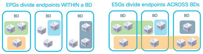
The following table illustrates the difference between EPGs and ESGs.
Table 5 Comparison between EPGs and ESGs
|
|
EPGs |
ESGs |
| Traffic within the EPG/ESG is allowed without contracts |
Yes |
Yes |
| Traffic between EPGs/ESGs requires a contract |
Yes |
Yes |
| scope |
Bridge domain |
VRF |
| class-id |
local, global with inter-VRF contracts |
global |
| networking semantics |
Yes: for mapping of VLANs to Bridge domains, subnets for route leaking |
No, only security semantics |
| can be preferred group member |
Yes |
Yes |
| can be used with vzAny |
Yes |
Yes |
| can be used with service graph |
Yes |
Yes |
| works with Multi-Pod |
Yes |
Yes |
| Works with Multi-Site |
Yes |
Not as of ACI 6.0(1) |
Implementing a Network-centric Topology
If you need to implement a topology with simple segmentation, you can create one or more bridge domains and EPGs and use the mapping of 1 bridge domain = 1 EPG = 1 VLAN.
You can then configure the bridge domains for unknown unicast flooding mode. See the section "Bridge domain design considerations" for more details.
In the Cisco ACI object model, the bridge domain has to have a relation with a VRF instance, so even if you require a pure Layer 2 network, you must still create a VRF instance and associate the bridge domain with that VRF instance.
If a reference is missing, Cisco ACI tries to resolve the relation to objects from tenant common.
You can control whether the association of the bridge domain with the VRF from tenant common is enough to enable bridging or routing by configuring the Instrumentation Policy (Tenant common > Policies > Protocol Policies > Connectivity Instrumentation Policy).
Default Gateway for the Servers
With this design, the default gateway can be outside of the Cisco ACI fabric itself, or Cisco ACI can be the default gateway.
To make Cisco ACI the default gateway for the servers, you need to configure the bridge domain with a subnet and enable unicast routing in the bridge domain.
Making Cisco ACI the default gateway and hence using Cisco ACI for routing traffic requires a minimum understanding of how Cisco ACI learns the IP addresses of the servers and how it populates the endpoint database.
Before moving the default gateway to Cisco ACI, make sure you verify whether the following type of servers are present:
● Servers with active/active transmit load-balancing teaming
● Clustered servers where multiple servers send traffic with the same source IP address
● Microsoft network load balancing servers
If these types of servers are present, you should first understand how to tune dataplane learning in the bridge domain before making Cisco ACI the default gateway for them. Refer to the "Endpoint Learning Considerations" section for more information.
Assigning Servers to Endpoint Groups
To connect servers to a bridge domain, you need to define the endpoint group and to define which leaf switch, port, or VLAN belongs to which EPG. You can do this in two ways:
● From Tenant > Application Profiles > Application EPGs > EPG by using Static Ports or Static Leafs
● From Fabric >Access Policies > Policies > Global > Attachable Access Entity Profiles > Application EPGs
Layer 2 Connectivity to the Outside with Network Centric Deployments
Connecting Cisco ACI to an external Layer 2 network with a network-centric design is easy because the bridge domain has a 1:1 mapping with a VLAN, thus there is less risk of introducing loops by merging multiple external Layer 2 domains using a bridge domain.
The connectivity can consist of a vPC to an external Layer 2 network, with multiple VLANs, each VLAN mapped to a different bridge domain and EPG.
The main design considerations with this topology are:
● Avoiding traffic blackholing due to missing Layer 2 entries. This is achieved by configuring the bridge domain for unknown unicast flooding instead of hardware-proxy.
● Limiting the impact of TCN BPDUs on the endpoint table.
You can limit the impact of TCN BPDUs on the endpoint table by doing one of two things:
● If the external network connectivity to Cisco ACI is kept loop-free by Spanning Tree Protocol, then you should reduce the impact of TCN BPDUs by making sure that the external Layer 2 network uses a VLAN on the EPG that is different from the VLAN used by servers that belong to the same EPG and are directly attached to Cisco ACI.
● If the external network connects to Cisco ACI in an intrinsically loop-free way, such as by using a single vPC, you could consider filtering BPDUs from the external network. However, this should be done only if you are sure that no loop can be introduced by incorrect cabling or by a misconfigured port channel. Hence, you should make sure LACP is used to negotiate the port channel and that LACP suspend individual ports is enabled.
The "Connecting EPGs to External Switches" section provides additional details about connecting a bridge domain to an external Layer 2 network.
Using VRF Unenforced Mode or Preferred Groups or vzAny with Network Centric Deployments
For a simple network-centric Cisco ACI implementation, initially you may want to define a permit-any-any type of configuration where all EPGs can talk. This can be done in three ways:
● Configuring the VRF for unenforced mode
● Enabling preferred groups and putting all the EPGs in the preferred group
● Configuring vzAny to provide and consume a permit-any-any contact
Figure 43 illustrates the three options.
The first option configures the entire VRF to allow all EPGs to talk to each other.
Preferred groups let you specify which EPGs can talk without contracts; you can also put EPGs outside of the preferred groups. To allow servers in the EPGs outside of the preferred group to send traffic to EPGs in the preferred group, you need to configure a contract between the EPGs.
The third option consists of making vzAny (also known as EPG collection for VRF) a provider and consumer of a permit-any-any contract.
The second and third approach are the most flexible because they make it easier to migrate to a configuration with more specific EPG-to-EPG contracts:
● If you used the preferred group, you can, in the next phase, move EPGs outside of the preferred group and configure contracts.
● If you used vzAny, you can, in the next phase, either add a redirect to a firewall instead of a permit to apply security rules on the firewall, or you can add more specific EPG-to-EPG contracts with an allowed list followed by a deny to gradually add more filtering between EPGs. This is possible because in Cisco ACI, more specific EPG-to-EPG rules have priority over the vzAny-to-vzAny rule.
For more information about contracts, refer to the "Contract design considerations" section.
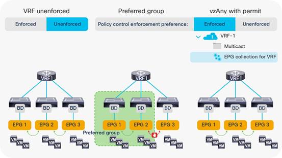
Using ESGs to Create the Equivalent of Multiple Preferred Groups
There can only be one Preferred Group per VRF. Endpoints that are part of the same ESG can communicate without any contract. In case you want to create multiple groups of EPGs where within each group endpoints can communicate without any contracts you can use ESGs to segment the VRF into multiple groups.
Starting with ACI 5.2(1) you can configure an ESG to match all the traffic from one or more EPGs. This is done with the EPG selector. By using the EPG selector, you can create multiple ESGs each aggregating multiple EPGs. The ESGs created with this approach are equivalent to having multiple Preferred Groups, with the only difference that an ESG cannot include an External EPG. Between an ESG and an External EPG you need to define a contract.
Figure 44 illustrates this point: ESG A is configured to match EGP 1, EPG 2, EPG 3, and ESG B is configured to match EPG 4, EPG 5, and EPG 6. Traffic from and to endpoints that belong to EPG1, 2, 3 is allowed to and from endpoints that belong to EPG 1, 2, 3, and similarly traffic from and to endpoints that belong to EPG 4, 5, 6 is allowed to and from endpoints that belong to EPG 4, 5, 6, but traffic between endpoints of EPG 1, 2, 3 to and from EPG 4, 5, 6 requires a contract.
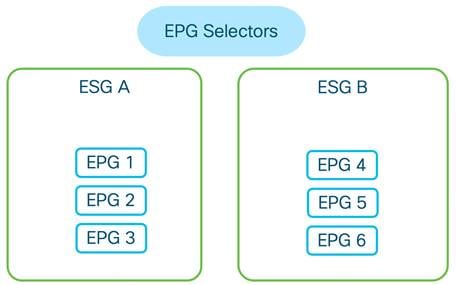
Implementing a Tenant Design With Segmentation Using EPGs or ESGs (Application-centric)
If you implement a Cisco ACI design with segmentation of bridge domain in multiple EPGs or with ESGs, the following design considerations apply:
● Define how many security zones you want to introduce into the topology.
● Plan on making Cisco ACI the default gateway for servers.
● Before making Cisco ACI the default gateway for the servers, make sure you know how to tune dataplane learning for the special cases of NIC teaming active/active, for clustered servers, and for MNLB servers.
● For bridge domains connected to an external Layer 2 network, use the unknown unicast flooding option in the bridge domain. Also make sure you read the "Connecting EPGs to External Switches" section.
● Carve EPGs per bridge domain based on the number of security zones, keeping in mind the verified scalability limits for EPGs and contracts.
● You have to use a different VLAN (or different VLANs) for each EPG in the same bridge domain on the same leaf switch. In practice, you should try to use a different VLAN for each EPG in the same bridge domain. VLAN re-use on the same leaf switch is only possible on a different bridge domains. For more information about VLAN re-use, see the "EPG and VLANs" section.
● Make sure that the number of EPG plus bridge domains utilized on a single leaf switch is less than the verified scalability limit. At the time of this writing, the maximum number of EPG plus bridge domains per leaf switch is 3960.
● Make sure you understand contract rules priorities to define correctly the EPG-to-EPG filtering rules and ESG-to-ESG filtering rules by using permit, deny, and optionally service graph redirect.
● You can change the default action for traffic between EPGs in the VRF to be permitted or redirected to a firewall by using vzAny with contracts.
● Configure policy CAM compression for contract filters.
When migrating to an application-centric design, you should start by defining how many security zones you need to define in the tenant network.
Let’s assume, for instance, that you need three security zones: IT, non-IT, and shared services, as shown in Figure 45.
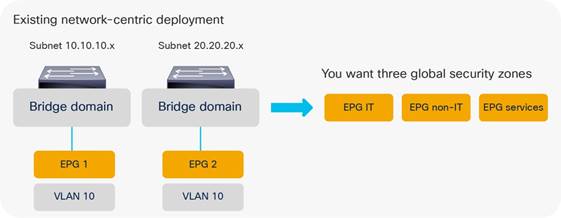
You can use one of the following approaches to introduce these security zones:
● Simply add an IT-EPG to BD1 and BD2, BD3, and so on, which results in a total number of EPGs that is equal to the number of security zones times the number of bridge domains, as shown in Figure 46.
● Reduce the number of bridge domains by merging them, ideally into one bridge domain and adding three EPGs to the single bridge domain, as shown in Figure 47.
● Define 1 EPG per bridge domain and use endpoint security groups (ESGs) to create the IT, non-IT and services security zone.
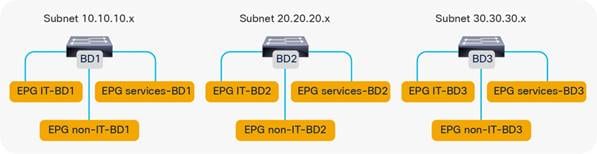
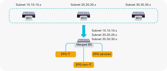
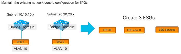
Adding EPGs to Existing Bridge Domains
The approach of creating additional EPGs in the existing bridge domains has the advantage of maintaining an existing Layer 2 design or bridge domain configuration by just adding security zones.
The disadvantages of adding EPGs to bridge domains are mostly related to scale and manageability:
● At the time of this writing, the validated number of EPG plus bridge domains per leaf switch is 3960.
● The number of EPGs and contracts can also grow significantly.
With many bridge domains, you are likely going to have many EPGs, and if all EPGs need to talk to all EPGs, the hardware consumption of the policy CAM entry becomes, in the order of magnitude of # EPGs * (# EPG – 1) * the number of filters, because of all of the EPG pairs that need to be defined.
The verified scalability guide states that a single EPG providing one contract consumed by 1,000 EPGs is a validated design. The verified scalability guide also states that the validated scale for multiple EPGs providing the same contract is a maximum of 100 EPGs, and the maximum number of EPGs consuming the same contract (provided by multiple EPGs) is 100 as well.
Merging Bridge Domains and Subnets (with Flood in Encapsulation)
With the approach of merging bridge domains into one, the number of EPGs and contracts is more manageable. But, because all EPGs and VLANs are in the same bridge domain, it may be necessary to use the flooding optimization features that Cisco ACI offers.
Flood in encapsulation is a feature that can be used on -EX and later leaf switches. The feature lets you scope the flooding domain to the individual VLANs on which the traffic is received. This is roughly equivalent to scoping the flooding to the EPGs.
Designs based on merged bridge domains with flood in encapsulation have the following characteristics:
● Cisco ACI scopes all unknown unicast and multicast flooded traffic, broadcast traffic, and control plane traffic in the same VLAN.
● Cisco ACI performs proxy ARP to forward traffic between servers that are in different VLANs. Because of this, traffic between EPGs (or rather between different VLANs) is routed even if the servers are in the same subnet.
● Flood in encapsulation also works with VMM domains.
Note: When using Flood in Encapsulation it is recommended to use a separate VLAN pool for EPGs of different Bridge Domains.
For more details, refer to the "Bridge domain design considerations" section.
When using a single bridge domain with multiple subnets, the following considerations apply:
● The DHCP server configuration may have to be modified to keep into account that all DHCP requests are originated from the primary subnet.
● Cisco ACI works fine with a large number of subnets under the same bridge domain, as described in the Verified Scalability Guide. The number that is validated at the time of this writing is 1,000 subnets under the same bridge domain with normal flooding configurations and 400 subnets with Flood in Encapsulation, but when using more than ~200 subnets under the same bridge domain, configuration changes performed to individual bridge domains in a nonbulk manner (for instance, using GUI or CLI configurations) can take a great deal of time to be applied to the fabric.
Using Endpoint Security Groups
Using Endpoint Security Groups has the advantage of preserving the existing EPG and bridge domain design. When using ESGs, the EPG function is primarily the mapping of the traffic to the correct Bridge Domain, while the ESG provides the classification function of the endpoints into security zones.
Starting with Cisco ACI 5.2(1), you can classify endpoints into ESGs in the following ways:
● By matching an EPG
● By matching a subnet or a host IP address
● By tagging a bridge domain subnet or in other words by classifying the traffic based on the bridge domain subnet
● By tagging the MAC or IP address of an endpoint and matching the tag, or in other words by classifying the traffic based on MAC or IP address
● By tagging a virtual machine
You can also start from a network-centric deployment with 1 EPG = 1 bridge domain, then adding ESGs to create the equivalent of multiple preferred groups and later define more precise ESGs by matching specific MAC and IP addresses.
Adding Filtering Rules with Contracts and Firewalls with vzAny and Service Graph Redirect
After dividing the bridge domains in security zones, you need to add contracts between them. The contract configuration can follow approaches such as these:
● Adding individual contracts between EPGs or ESGs, with a default implicit deny
● Configuring vzAny with a contract to redirect all traffic to an external firewall and using specific EPG-to-EPG or ESGs-to-ESGs contracts for specific traffic
The first approach is the allowed list approach, where all traffic is denied unless there is a specific contract to permit EPG-to-EPG or ESG-to-ESG traffic.
The second approach consists of configuring vzAny as a provider and consumer of a contract with service graph redirect to one or more firewalls. With this approach, any EPG-to-EPG or ESG-to-ESG traffic (even within the same bridge domain) is redirected to a firewall for ACL filtering. This approach uses Cisco ACI for segmentation and the firewall for ACL filtering. You can configure EPG-to-EPG or ESG-to-ESG specific contracts that have higher priority than the vzAny with redirect to allow, for instance, backup traffic directly using the Cisco ACI fabric without sending it to a firewall. Figure 49 illustrates this approach.
Two or more firewalls are connected to the Cisco ACI fabric (you can also cluster several firewalls with symmetric policy-based routing (PBR) hashing). By using vzAny in conjunction with a service graph redirect attached to a contract, all traffic between EPGs or ESGs is redirected to the firewall pair. For instance, traffic between EPG IT-BD1 and non-IT-BD1 has to go through the firewall first and, similarly, traffic between EPG non-IT-BD1 and services-BD1.
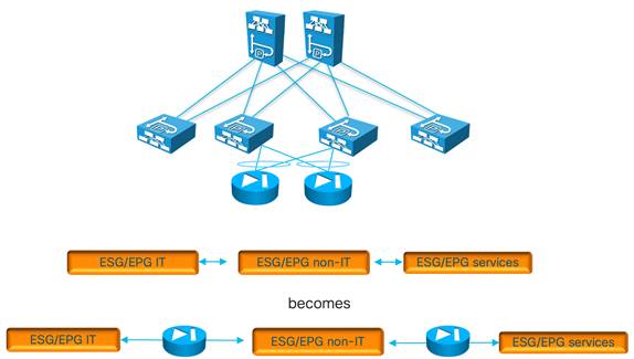
Figure 50 illustrates the configuration of vzAny with the contract to redirect the traffic.
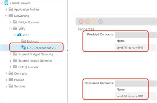
With application-centric deployments, the policy CAM is more utilized than with network-centric deployments because of the number of EPGs, contracts, and filters.
Depending on the leaf switch hardware, Cisco ACI offers many optimizations to either allocate more policy CAM space or to reduce the policy CAM consumption:
● Cisco ACI leaf switches can be configured for policy-CAM-intensive profiles
● Range operations use one entry only in TCAM
● Bidirectional subjects take one entry
● Filters can be reused with an indirection feature (at the cost of granularity of hardware statistics that you may be using when troubleshooting)
Note Contracts compression can only be used with permit rules, it cannot be enabled on rules with service graph redirect or with deny.
Figure 51 illustrates how to enable policy CAM compression when configuring filters.
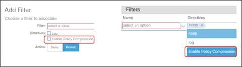
For more information about contracts, refer to the "Contract design considerations" section and to the following white paper:
Default Gateway (Subnet) Design Considerations
Bridge Domain Subnet, SVI, Pervasive Gateway
The Cisco ACI fabric operates as an anycast gateway for the IP address defined in the bridge domain subnet configuration. This is known as a pervasive gateway. The configuration is found under Tenant > Networking > Bridge Domains > Subnets.
The pervasive gateway Switch Virtual Interface (SVI) is configured on a leaf switch wherever the bridge domain of the tenant is present.
Subnet Configuration: Under the Bridge Domain and Why Not Under the EPG
When connecting servers to Cisco ACI, you should set the servers' default gateway as the subnet IP address of the bridge domain.
Subnets can have the following properties:
● Advertised Externally: This option indicates that this subnet should be advertised to an external router by a border leaf switch (through an L3Out connection). A subnet that is configured to be advertised externally is also referred to as a public subnet.
● Private to VRF: This option indicates that this subnet is contained within the Cisco ACI fabric and is not advertised to external routers by the border leaf switch. This option has been removed in the latest releases as it is the opposite of Advertised Externally.
● Shared Between VRF Instances: This option is for shared services. It is used to indicate that this subnet should be leaked to one or more VRF instances. The shared subnet attribute is applicable to both public and private subnets.
Cisco ACI also lets you enter the subnet IP address at the EPG level for designs that require VRF leaking. In Cisco ACI releases earlier than release 2.3, the subnet defined under an EPG that is the provider of shared services had to be used as the default gateway for the servers. You can find more information about this topic in the "VRF sharing design considerations" section.
Starting with Cisco ACI release 2.3, the subnet defined at the bridge domain should be used as the default gateway also with VRF sharing.
The differences between a subnet under the bridge domain and a subnet under the EPG are as follows:
● Subnet under the bridge domain: If you do not plan any route leaking among VRF instances and tenants, the subnets should be placed only under the bridge domain. If Cisco ACI provides the default gateway function, the IP address of the SVI providing the default gateway function should be entered under the bridge domain.
● Subnet under the EPG: If you plan to make servers on a given EPG accessible from other tenants (such as in the case of shared services), you must configure the provider-side subnet also at the EPG level. This is because a contract will then also place a route for this subnet in the respective VRF instances that consume this EPG. The subnets configured on the EPGs under the same VRF must be nonoverlapping. The subnet defined under the EPG should have the No Default SVI Gateway option selected.
The bridge domain lets you configure two different MAC addresses for the subnet:
● Custom MAC address
● Virtual MAC address
The primary use case for this feature is related to Layer 2 extension of a bridge domain if you connect two fabrics at Layer 2 in order for each fabric to have a different custom MAC address. This feature is normally referred to as the common pervasive gateway.
You can find more information about this feature at the following link:
https://www.cisco.com/c/en/us/td/docs/dcn/aci/apic/5x/l3-configuration/cisco-apic-layer-3-networking-configuration-guide-51x/m_common_pervasive_gateway_v2.html
If you configure a unique custom MAC address per fabric, you will also want to configure a virtual MAC address that is identical in both fabrics to help ensure a transparent vMotion experience.
When the fabric sends an ARP request from a pervasive SVI, it uses the custom MAC address.
When the server sends ARP requests for its default gateway (the virtual IP address for the subnet), the MAC address that it gets in the ARP response is the virtual MAC address.
Note: In the Cisco Nexus 93128TX, 9372PX and TX, and 9396PX and TX platforms, when the virtual MAC address is configured, traffic is routed only if it is sent to the virtual MAC address. If a server chooses to send traffic to the custom MAC address, this traffic cannot be routed.
The VRF is the dataplane segmentation element for traffic within or between tenants. Routed traffic uses the VRF as the VNID. Even if Layer 2 traffic uses the bridge domain identifier, the VRF is always necessary in the object tree for a bridge domain to be instantiated.
Therefore, you need either to create a VRF in the tenant or refer to a VRF in the common tenant.
There is no 1:1 relationship between tenants and VRF instances:
● A tenant can rely on a VRF from the common tenant.
● A tenant can contain multiple VRF instances.
A popular design approach in multitenant environments where you need to share an L3Out connection is to configure bridge domains and EPGs in individual user tenants while referring to a VRF residing in the common tenant.
Shared L3Out connections can be simple or complex configurations, depending on the option that you choose. This section covers the simple and recommended options of using a VRF from the common tenant.
When creating a VRF, you must consider the following choices:
● Whether you want the traffic for all bridge domains and EPGs related to a VRF to be filtered according to contracts
● The policy control enforcement direction (ingress or egress) for the traffic between EPGs and the outside. The default is "ingress," which means that the "ingress" leaf switch (it would be more accurate to say, the "compute" leaf switch) filters the traffic from the Cisco ACI fabric to the L3Out, and traffic from the L3Out to servers connected to the Cisco ACI fabric is filtered on the leaf switch where the server is connected.
Each tenant can include multiple VRF instances. The current number of supported VRF instances per tenant is documented in the Verified Scalability Guide:
Regardless of the published limits, it is good practice to distribute VRF instances across different tenants to have better control plane distribution on different Cisco APICs.
VRF Instances and Bridge Domains in the Common Tenant
In this scenario, you create the VRF instance and bridge domains in the common tenant and create EPGs in the individual user tenants. You then associate the EPGs with the bridge domains of the common tenant. This configuration can use static or dynamic routing (Figure 52).
The configuration in the common tenant is as follows:
1. Configure a VRF under the common tenant.
2. Configure an L3Out under the common tenant and associate it with the VRF.
3. Configure the bridge domains and subnets under the common tenant.
4. Associate the bridge domains with the VRF instance and L3Out connection.
The configuration in each tenant is as follows:
1. Under each tenant, configure EPGs and associate the EPGs with the bridge domain in the common tenant.
2. Configure a contract and application profile under each tenant.
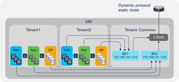
This approach has the advantage that each tenant has its own EPGs and contracts.
This approach has the following disadvantages:
● Each bridge domain and subnet are visible to all tenants.
● All tenants use the same VRF instance. Hence, they cannot use overlapping IP addresses.
VRF Instances in the Common Tenant and Bridge Domains in User Tenants
In this configuration, you create a VRF in the common tenant and create bridge domains and EPGs in the individual user tenants. Then, you associate the bridge domain of each tenant with the VRF instance in the common tenant as shown in Figure 53.
Configure the common tenant as follows:
1. Configure a VRF instance under the common tenant.
2. Configure an L3Out under the common tenant and associate it with the VRF instance.
Configure the individual tenants as follows:
1. Configure a bridge domain and subnet under each customer tenant.
2. Associate the bridge domain with the VRF in the common tenant and the L3Out.
3. Under each tenant, configure EPGs and associate the EPGs with the bridge domain in the tenant itself.
4. Configure contracts and application profiles under each tenant.
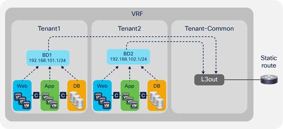
The advantage of this approach is that each tenant can see only its own bridge domain and subnet.
VRF Ingress Versus VRF Egress Filtering Design Considerations
The VRF can be configured for ingress policy enforcement or egress policy enforcement.
Before describing what this feature does, it is important to clarify the terminology "ingress" filtering and "egress" filtering and to underline the difference between "ingress filtering/egress filtering" and "VRF ingress filtering/VRF egress filtering."
In Cisco ACI, policy filtering is based on the lookup of the source class ID and destination class ID in the policy-cam. If the "ingress" leaf switch, that is the leaf switch where the traffic is received from the host, has all the information to derive the source and destination class ID, the filtering is performed on the very "ingress" leaf switch. While the source class ID is always known because of the EPG configuration on the leaf switch where traffic is received, the ingress leaf switch may not have the information about the destination class ID. This information is available if either the destination endpoint is local to the very leaf switch, or in case the MAC/IP address of the destination endpoint is populated in the forwarding tables because of previous traffic between the local leaf switch endpoints and the remote endpoint. If the "ingress" leaf switch doesn’t have the information about the destination endpoint (and, as a result, of the destination class ID), Cisco ACI forwards the traffic to the "egress" leaf switch, where the Cisco ACI leaf switch can derive the destination class ID and perform policy filtering. An exception to this filtering and forwarding behavior is the case of the use of vzAny to vzAny contracts, in which case filtering is always performed on the egress leaf switch.
When it comes to the "VRF ingress" and "VRF egress" configurations, the "ingress" and "egress" don’t refer generically to traffic between EPGs of Cisco ACI leaf switches, instead it refers only to policy filtering for traffic between an EPG and the external EPG. This configuration doesn’t change anything about how filtering is done for traffic between any other EPG pairs.
It would be more accurate to call the VRF options as "compute leaf policy enforcement" and "border leaf switch policy enforcement." This configuration controls whether the ACL filtering performed by contracts that are configured between the external EPGs and EPGs is implemented on the leaf switch where the endpoint is or on the border leaf switch.
You can configure the VRF instance for ingress or egress policy by selecting the Policy Control Enforcement Direction option Egress under Tenants > Networking > VRFs.
The configuration options do the following:
● VRF ingress policy enforcement means that the ACL filtering performed by the contract is implemented on the leaf switch where the endpoint is located. This configuration makes the policy CAM of the border leaf switch less utilized because the policy CAM filtering rules are configured on the "compute" leaf switches. With ingress policy enforcement, the filtering happens consistently on the "compute" leaf switch for both directions of the traffic.
● VRF egress policy enforcement means that the ACL filtering performed by the contract is also implemented on the border leaf switch. This makes the policy CAM of the border leaf switch more utilized. With egress policy enforcement, the border leaf switch does the filtering for the L3Out-to-EPG direction after the endpoint has been learned as a result of previous traffic. Otherwise, if the endpoint to destination class mapping is not yet known on the border leaf switch, the policy CAM filtering happens on the compute leaf switch.
The VRF ingress policy enforcement feature is implemented by populating the information about the external EPGs on all the compute leaf switches that have a contract with the external EPGs and by configuring the hardware on the border leaf switch in a way that traffic from the L3Out is forwarded to the compute leaf switch. This improves policy CAM utilization on the border leaf switches by distributing the filtering function across all regular leaf switches, but it distributes the programming of the external EPG entries on all the leaf switches. This is mostly beneficial in case you are using first-generation leaf switches and in the case where the external EPG table is not heavily utilized. The VRF egress policy enforcement feature optimizes the use of entries for the external EPGs by keeping the table configured only on the border leaf switch.
You can find more information about the policy filtering and the VRF ingress versus VRF egress configuration in the following white paper: https://www.cisco.com/c/en/us/solutions/collateral/data-center-virtualization/application-centric-infrastructure/white-paper-c11-743951.html#Trafficflowdescription
Some features scale or work better with VRF ingress filtering and other features work better with VRF egress filtering. At the time of this writing (that is, as of Cisco ACI release 6.0(1)), most features work better with, and some require, VRF ingress filtering. The features that require VRF ingress filtering are:
● IP-based EPGs for microsegmentation
● Direct server return
● GOLF
● Multi-Site with a Layer 4 to Layer 7 service graph based on PBR for intra-VRF L3Out to EPG contracts
The features at the time of this writing that require VRF egress filtering are:
● Quality of Service (QoS) on the L3Out using a contract
● Microsoft network load balancing (NLB): you can still deploy MNLB with the VRF set for ingress filtering. But, if you need to configure a contract between a L3Out and the MNLB EPG, you need to use a workaround. For instance, you can set the L3Out and the MNLB EPG on different VRF instances. The MNLB configuration described in the Cisco APIC Layer 3 Networking Configuration Guide provides additional workarounds.
● Integration with Cisco Software-Defined Access (SD Access)
Note: In case you use features that require the VRF to be set in different modes, you can consider using multiple VRF instances and VRF sharing.
In terms of scale, the use of VRF ingress filtering optimizes the policy-cam utilization on the border leaf switch, while VRF egress filtering optimizes the programming of external prefixes by limiting them to the border leaf switch. Table 6 illustrates the pros and cons from a scalability perspective.
Table 6 VRF ingress versus egress filtering and hardware resources
|
|
Ingress |
Egress |
| Policy-cam Rules |
Only on non-border leaf switches |
On non border leaf switches and border leaf switches |
| External EPGs prefixes |
On non border leaf switches and border leaf switches |
Only on border leaf switches |
| Summary |
Optimizes policy-cam on border leaf switches |
Avoids pushing of external EPG prefixes to all non-border leaf switches |
Bridge Domain Design Considerations
The main bridge domain configuration options that should be considered when tuning bridge domain behavior are as follows:
● Whether to use hardware proxy or unknown unicast flooding
● Whether to enable or disable Address Resolution Protocol (ARP) flooding
● Whether to enable or disable unicast routing
● Whether or not to define a subnet
● Whether to define additional subnets in the same bridge domain
● Whether to constrain the learning of the endpoints to the subnet address space
● Whether to configure the endpoint retention policy
● Whether to use Flood in Encapsulation
With the Layer 2 unknown unicast option set to hardware proxy, Cisco ACI forwards Layer 2 unknown unicast traffic to the destination leaf switch and port without relying on flood-and-learn behavior, as long as the MAC address is known to the spine switch. Hardware proxy works well when the hosts connected to the fabric are not silent hosts because it allows Cisco ACI to program the spine switch proxy table with the MAC-to-VTEP information.
With the Layer 2 unknown unicast option set to flood, the forwarding does not use the spine switch-proxy database: Layer 2 unknown unicast packets are flooded in the bridge domain using one of the multicast trees rooted in the spine switches.
If ARP flooding is enabled, ARP traffic will be flooded inside the bridge domain in the fabric as per regular ARP handling in traditional networks. If the ARP flooding option is deselected, Cisco ACI forwards the ARP frame to the leaf switch and port where the endpoint with the target IP address in the ARP packet payload is located. This effectively eliminates ARP flooding on the bridge domain in the Cisco ACI fabric. This option applies only if unicast routing is enabled on the bridge domain. If unicast routing is disabled, ARP traffic is always flooded.
If the unicast routing option in the Layer 3 Configurations tab is set and if a subnet address is configured, the fabric provides the default gateway function and routes the traffic. The subnet address configures the SVI IP addresses (default gateway) for the bridge domain. Enabling unicast routing also enables ACI to learn the endpoint IP-to-VTEP mapping for this bridge domain. The IP address learning is not dependent upon having a subnet configured under the bridge domain.
The limit local IP Learning to BD/Subnet is used to configure the fabric not to learn IP addresses from a subnet other than the one configured on the bridge domain. If Enforce Subnet Check is enabled globally, this option is not necessary.
Note: Many bridge domain configuration changes require removal of the MAC and IP address entries from the hardware tables of the leaf switches, so the changes are disruptive. When changing the bridge domain configuration, keep in mind that this change can cause traffic disruption.
Bridge Domain Configuration for Migration Topologies
When connecting to an existing Layer 2 network, you should consider deploying a bridge domain with L2 Unknown Unicast set to Flooding . This means enabling flooding for Layer 2 unknown unicast traffic and ARP flooding in the bridge domain.
Consider the topology of Figure 54. The reason for using unknown unicast flooding instead of hardware proxy in the bridge domain is that Cisco ACI may take a long time to learn the MAC addresses and IP addresses of the hosts connected to the existing network (switch A and switch B). Servers connected to leaf 1 and leaf 2 may trigger the learning of the MAC addresses of the servers connected to switch A and B because they would perform an ARP address resolution for them, which would then make hardware proxy a viable option. Now, imagine that the link connecting switch A to leaf 3 goes down, and that the link connecting switch B to leaf 4 becomes a forwarding link. All the endpoints learned on leaf 3 are now cleared from the endpoint database. Servers connected to leaf 1 and leaf 2 still have valid ARP entries for the hosts connected to switch A and switch B, so they will not perform an ARP address resolution again immediately. If the servers connected to leaf 1 and leaf 2 send frames to the servers connected to switch A and switch B, these will be dropped until the servers connected to switch A and switch B send out some traffic that updates the entries on leaf 4. Switches A and B may not flood any traffic to the Cisco ACI leaf switches until the MAC entries expire in the existing network forwarding tables. The servers in the existing network may not send an ARP request until the ARP caches expire. Therefore, to avoid traffic disruption you should set the bridge domain that connects to switches A and B for unknown unicast flooding.
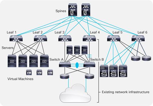
When using the bridge domain configured for Layer 2 unknown unicast flooding, you may also want to select the option called Clear Remote MAC Entries. Selecting Clear Remote MAC Entries helps ensure that, when the leaf switch ports connected to the active Layer 2 path go down, the MAC address entries of the endpoints are cleared both on the local leaf switch (as for leaf 3 in the previous example) and associated remote endpoint entries in the tables of the other leaf switches in the fabric (as for leaf switches 1, 2, 4, 5, and 6 in the previous example). The reason for this setting is that the alternative Layer 2 path between switch B and leaf 4 in the example may be activated, and clearing the remote table on all the leaf switches prevents traffic from becoming black-holed to the previous active Layer 2 path (leaf 3 in the example).
By default, bridge domains are configured with Multidestination Flooding set to Flood in Bridge Domain. This configuration means that when a multidestination frame (or an unknown unicast with unknown unicast flooding selected) is received from an EPG on a VLAN, it is flooded in the bridge domain (with the exception of BPDUs which are flooded in the FD_VLAN VNID).
Consider the example shown in Figure 55. In this example, bridge domain 1 (BD1) has two EPGs, EPG1 and EPG2, and they are respectively configured with a binding to VLANs 5, 6, 7, and 8 and VLANs 9, 10, 11, and 12. The right side of the figure shows to which ports the EPGs have a binding. EPG1 has a binding to leaf 1, port 1, on VLAN 5; leaf 1, port 2, on VLAN 6; leaf 4, port 5, on VLAN 5; leaf 4, port 6, on VLAN 7; and so on. These ports are all part of the same broadcast domain, regardless of which VLAN is used. For example, if you send a broadcast to leaf 1, port 1/1, on VLAN 5, it is sent out from all ports that are in the bridge domain across all EPGs, regardless of the VLAN encapsulation.
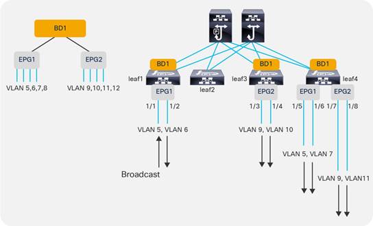
BPDU Handling in the Bridge Domain
When a switching device is attached to a leaf switch, a mechanism is needed to help ensure interoperability between a routed VXLAN-based fabric and the loop-prevention features used by external networks to prevent loops inside Layer 2 broadcast domains.
Cisco ACI addresses this by flooding external BPDUs within a specific encapsulation, not through the entire bridge domain. Because per-VLAN Spanning Tree Protocol carries the VLAN information embedded in the BPDU packet, the Cisco ACI fabric must also be configured to take into account the VLAN number itself.
For instance, if EPG1, port 1/1, is configured to match VLAN 5 from a switch, another port of that switch for that same Layer 2 domain can be connected only to EPG1 using the same encapsulation of VLAN 5. Otherwise, the external switch would receive the BPDU for VLAN 5 tagged with a different VLAN number. Cisco ACI floods BPDUs only between the ports in the bridge domain that have the same encapsulation.
As Figure 56 illustrates, if you connect an external switch to leaf 1, port 1/1, the BPDU sent by the external switch would be flooded only to port 1/5 of leaf 4 because it is also part of EPG1 and tagged with VLAN 5.
As described in the "Understanding VLAN use in ACI and which VXLAN they are mapped to" section, BPDUs are flooded throughout the fabric with the FD_VLAN VXLAN VNID, which is a different VNID than the one associated with the bridge domain to which the EPG belongs. This is to keep the scope of BPDU flooding separate from general multidestination traffic in the bridge domain.
Note: When the EPG is configured with intra-EPG isolation enabled, Cisco ACI does not forward BPDUs.
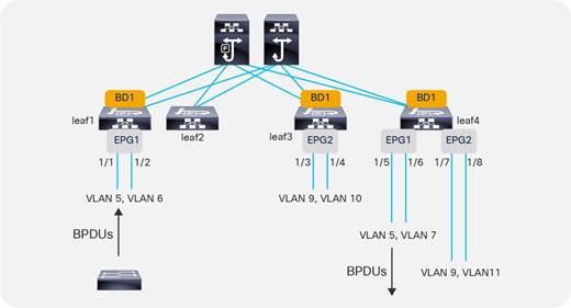
The bridge domain Multi Destination Flooding option can be set to flood in encapsulation. Flood in encapsulation is a feature that can be useful when merging multiple existing Layer 2 domains into a single bridge domain and you want to scope the flooding domain to the VLAN from which the traffic came.
With flood in encapsulation, Cisco ACI floods packets to all of the EPGs having the same VLAN encapsulation coming from same namespace (that is, from the same VLAN pool under the same domain). This is the FD_VLAN that was previously described in the "Defining VLAN pools and domains" section. Because normally you use a different VLAN in different EPGs, using flood in encapsulation is roughly equivalent to scoping the flooding to the EPGs.
Designs based on merged bridge domains with flood in encapsulation have the following characteristics:
● Flood in encapsulation can be configured on the bridge domain or on specific EPGs.
● With flood in encapsulation, Cisco ACI scopes all unknown unicast and multicast flooded traffic, broadcast traffic, and control plane traffic in the same VLAN.
● Prior to Cisco ACI 3.1, flood in encapsulation was scoping primarily unknown unicast traffic, link-local traffic, broadcast traffic, and Layer 2 multicast traffic, but not protocol traffic. Starting from Cisco ACI 3.1, flood in encapsulation is able to limit flooding of the following types of traffic: multicast traffic, broadcast traffic, link-local traffic, unknown unicast traffic, OSPF, EIGRP, ISIS, BGP, STP, IGMP, PIM, ARP, GARP, RARP, ND, HSRP, and so on.
● Cisco ACI performs proxy ARP to forward traffic between servers that are in different VLANs. Because of this, traffic between EPGs (or rather, between different VLANs) is routed even if the servers are in the same subnet.
● Flood in encapsulation also works with VMM domains if the transport is based on VLANs and VXLANs. The support for VXLAN is available starting from Cisco ACI 3.2(5).
● Starting with Cisco ACI 4.2(6) and 5.1(3), storm control has been improved to work on all control plane protocol also with flood in encapsulation. Prior to these releases, storm control used in conjunction with flood in encapsulation didn’t rate limit ARP and DHCP.
● With flood in encapsulation, multicast is flooded only on the ports that are on the same VLAN as the incoming traffic. Even if Internet Group Management Protocol (IGMP) snooping is on, the multicast is flooded on the ports in the same encapsulation, the scope of the flooding is dependent on IGMP reports received per leaf switch. If there was an IGMP report on that specific leaf switch, traffic is sent to that port only if it is in the same encapsulation.
● With flood in encapsulation, given that ARP packets are sent to the CPU, there is the risk that one link could use all of the aggregate capacity that the global COPP allocated for ARP. Because of this, we recommend that you enable per protocol per interface COPP to ensure fairness among the ports that are part of the EPG/bridge domain.
Flood in encapsulation has the following requirements:
● You must use -EX or later leaf switches.
● MAC addresses in different VLANs that are in the same bridge domain must be unique.
● Different bridge domains should use different VLAN pools, that is EPGs of different bridge domains should be associated with domains that use different VLAN pools.
● Unicast routing must be enabled and a subnet must be configured on the bridge domain for Layer 2 communication between EPGs that are in the same subnet.
● The option for optimizing ARP in the bridge domain (no ARP flooding) cannot be used.
The following features either do not work in conjunction with the bridge domain where flood in encapsulation is enabled or have not been validated
● IPv6
● Multicast routing
● Microsegmentation
Note: Flood in encapsulation and microsegmentation are incompatible features because with flood in encapsulation Cisco ACI forwards traffic between endpoints in the same VLAN at Layer 2 without any proxy ARP involvement. In contrast, with microsegmentation the VLAN is a private VLAN and proxy ARP is required for all communication within the VLAN. Because of this, the two features try to set the VLAN and proxy ARP differently.
You can find more information about flood in encapsulation in the following document:
Using Hardware-Proxy to Reduce Flooding
Cisco ACI offers the following features to limit the amount of flooding in the bridge domain:
● Flood in encapsulation, which is designed to scope the flooding domains to EPG/VLANs.
● Hardware-proxy, which is focused on optimizing flooding for unknown unicast traffic while keeping the bridge domain as the flooding domain for other multidestination traffic.
When using hardware-proxy, you should consider enabling unicast routing and defining a subnet on the bridge domain. This is because with hardware-proxy on, if a MAC address has been aged out in the spine switch-proxy, traffic destined to this MAC address is dropped. For Cisco ACI to maintain an up-to-date endpoint database, Cisco ACI must perform an ARP address resolution of the IP addresses of the endpoints; this also refreshes the MAC address table.
If you want to reduce flooding in the bridge domain that is caused by Layer 2 unknown unicast frames, you should configure the following options:
● Configure hardware-proxy to remove unknown unicast flooding.
● Configure unicast routing to enable the learning of endpoint IP addresses.
● Configure a subnet to enable the bridge domain to use ARP to resolve endpoints when the endpoint retention policy expires, and also to enable the bridge domain to perform ARP gleaning for silent hosts. When configuring a subnet, you also should enable the option Limit IP Learning to Subnet.
● Define an endpoint retention policy. This is important if the ARP cache timeout of hosts is longer than the default timers for MAC address entries on the leaf and spine switches. With an endpoint retention policy defined, you can either tune the timers to last longer than the ARP cache on the servers, or, if you have defined a subnet IP address and unicast routing on the bridge domain, Cisco ACI will send ARP requests to for the hosts before the timer has expired, in which case the tuning may not be required. For more information about tuning the endpoint retention policy, refer to the "Endpoint Aging" section.
Note: The endpoint retention policy is configured as part of the bridge domain or of the VRF configuration. The endpoint retention policy configured at the bridge domain level controls the aging of the MAC addresses. The endpoint retention policy configured at the VRF level controls the aging of the IP addresses.
When changing bridge domain settings in a production network, use caution because endpoints that had been learned in the endpoint database may be then flushed after the change. This is because, in the current implementation, the VNID used by the same bridge domain configured for unknown unicast flooding or for hardware-proxy differs.
If you change the bridge domain settings from Layer 2 Unknown Unicast to Hardware-Proxy, the following could happen:
● Cisco ACI flushes the endpoints on the bridge domain.
● The ARP entries on the hosts may not expire immediately afterward.
● The host tries to send traffic to another host hence that host will effectively be generating unknown unicast MAC address traffic.
● This traffic in hardware-proxy mode is not flooded, but is sent to the spine switch proxy.
● The spine switch proxy does not have an updated entry unless the destination host has spoken after you changed the bridge domain settings.
● As a result, this traffic will be dropped.
Because of this, it is best to start a deployment with a bridge domain set to Hardware-Proxy and maybe change it later to Layer 2 Unknown Unicast Flooding if necessary, or have a script to ping all hosts in a bridge domain after the change so that Cisco ACI repopulates the endpoint information.
If the ARP flooding option is deselected, a Layer 3 lookup occurs for the target IP address of the ARP packet: Cisco ACI forwards the ARP packet like a Layer 3 unicast packet until it reaches the destination leaf switch and port.
With clustered servers or HA pairs of firewalls and load balancers, you need to configure ACI to flood Gratuitous ARP in a bridge domain, because after a failover, the same IP address may be using a different MAC address.
In these scenarios, Gratuitous ARP (GARP) is used to update host ARP caches or router ARP caches, so in this case you should select the ARP flooding option in the bridge domain.
GARP-based detection is an option that was introduced for first-generation switches. This option was useful when a host connected to a Cisco ACI leaf switch through an intermediate switch changed the MAC address for the same IP address, for instance because of a floating IP address. This resulted in a change of IP address to MAC address mapping on the same interface, and GARP-based detection was required to address this scenario.
In second generation Cisco ACI leaf switches, this option provides no benefits as long as IP address dataplane learning is enabled. It may be useful primarily if you need to disable IP address dataplane learning and if an endpoint moves and it sends a GARP right after, in which case this option punts GARP packet to the leaf switch CPU, thus allowing Cisco ACI to update the endpoint information despite IP address dataplane learning being disabled. Having said that, the per-VRF IP address dataplane learning configuration automatically sets GARP detection, so whether you configure this option or not is not important.
Note: Live Migration of a virtual machine is followed by a RARP packet generated by the virtualized host, and this doesn’t require GARP-based detection to function.
Layer 2 Multicast and IGMP Snooping in the Bridge Domain
Cisco ACI forwards multicast frames on the overlay multicast tree that is built between leaf and spine switches.
The Cisco ACI forwarding configuration options control how the frames are forwarded on the leaf switches.
Cisco ACI forwarding for non-routed multicast traffic works as follows:
● Layer 2 multicast frames—that is, multicast frames that do not have a multicast IP address—are flooded.
● Layer 3 multicast frames—that is, multicast frames with a multicast IP address--the forwarding in the bridge domain depends on the configurations of the bridge domain.
The following two bridge domain configurations allow optimizing the Layer 2 forwarding of IP address multicast frames with or without unicast routing enabled:
● IGMP snooping
● Optimized flood
IGMP snooping is on by default on the bridge domain, because the IGMP snooping policy "default" that is associated with the bridge domain defines IGMP snooping to be on.
It is better to define your own IGMP snooping policy so that you can change the querier configuration and the querier interval for this configuration alone without automatically changing many other configurations.
To have an IGMP querier, you can simply configure a subnet under the bridge domain, and you need to select the "Enable querier" option.
Cisco ACI refers to "unknown Layer 3 multicast" as a multicast IP address for which there was no IGMP report. Unknown Layer 3 multicast is a per-leaf switch concept, so a multicast IP address is an unknown Layer 3 multicast if on a given leaf switch there has not been an IGMP report. If there was an IGMP report such as an IGMP join on a leaf switch, then the multicast traffic for that multicast group is not an unknown Layer 3 multicast, and it is not flooded on the leaf switch if IGMP snooping is on.
If Optimized Flood is configured, and if an "unknown Layer 3 multicast" frame is received, this traffic is only forwarded to multicast router ports. If Optimized Flood is configured and a leaf switch receives traffic for a multicast group for which it has received an IGMP report, the traffic is sent only to the ports where the IGMP report was received.
Cisco ACI uses the multicast IP address to define the ports to which to forward the multicast frame, hence it is more granular than traditional IGMP snooping forwarding.
Bridge Domain Enforcement Status
By default, servers from an EPG of a given bridge domain (such as BD1) can ping the SVI (subnet) of another bridge domain (such as BD2). If you wish to constrain a host to be able to ping only the SVI of the bridge domain that it belongs to, you can use the BD Enforcement Status option configuration in the VRF as illustrated in Figure 57. This feature blocks ICMP, TCP, and UDP traffic to the subnet IP address of bridge domains that are different from the one to which the server belongs.
You can also specify IP addresses for devices that need to be able to reach the bridge domain SVIs regardless of to which bridge domain they are connected. This configuration option is available from System > System Settings > BD Enforced Exception List.
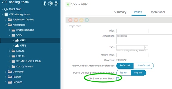
Summary of Bridge Domain Recommendations
The recommended bridge domain configuration that works in most scenarios consists of the following settings:
● With designs consisting of endpoints directly attached to the Cisco ACI leaf switches, we recommend configuring unicast routing, adding a subnet in the bridge domain, and configuring hardware-proxy.
● For bridge domains connected to existing Layer 2 networks, you should configure the bridge domain for unknown unicast flooding and select the Clear Remote MAC Entries option.
● Use of ARP flooding is often required because of the variety of teaming implementations and the potential presence of floating IP addresses.
● If you need to merge multiple Layer 2 domains in a single bridge domain, consider the use of flood in encapsulation.
● Except for some specific scenarios with first generation leaf switches, there is no need to configure GARP-based detection.
The EPG feature is the tool to map traffic from a leaf switch port to a bridge domain.
Traffic from endpoints is classified and grouped into EPGs based on various configurable criteria.
Cisco ACI can classify three types of endpoints:
● Physical endpoints
● Virtual endpoints
● External endpoints (endpoints that send traffic to the Cisco ACI fabric from an L3Out)
The EPG provides two main functionalities:
● Mapping traffic from an endpoint (a server, virtual machine, or container instance) to a bridge domain
● Mapping traffic from an endpoint (a server, virtual machine, or container instance) to a security zone.
The second function can be performed also with the feature called endpoint security groups (ESGs) for which you can find more information in the following document:
You can configure the classification of the endpoint traffic as follows:
● Based on Cisco ACI leaf switch incoming port and VLAN.
● Based on the network and mask or IP address for traffic originating outside the fabric. That is, traffic considered to be part of an external EPG, which is an object called L3extInstP and often referred to as "L3ext".
● Based on explicit virtual NIC (vNIC) assignment to a port group. At the hardware level, this translates into a classification based on a dynamic VLAN or VXLAN negotiated between Cisco ACI and the VMM.
● Based on the source IP address or subnet. For physical machines, this function requires the hardware to support source IP address classification (Cisco Nexus E platform leaf switches and later platforms).
● Based on the source MAC address. For physical machines, this requires the hardware to support MAC-based classification and Cisco ACI 2.1 or higher.
● Based on virtual machine attributes. This option assigns virtual machines to an EPG based on attributes associated with the virtual machine. At the hardware level, this translates into a classification based on MAC addresses.
This section illustrates the most common classification criteria, which is the criteria based on port and VLANs. You can find details about the other options at the following link: https://www.cisco.com/c/en/us/solutions/collateral/data-center-virtualization/application-centric-infrastructure/white-paper-c11-743951.html#Microsegmentation
With regard to the use of EPG and VLANs, certain topics have already been covered in this document. Refer to the relevant section:
● For overlapping VLANs, refer to the "Overlapping VLAN ranges" section under "Defining VLAN pools and domains".
● For Flood in Encapsulation, refer to the "Flood in Encapsulation" section in the "Bridge Domain Design Considerations" main section.
● VLAN scope port local, refer to the "VLAN Scope: Port Local Scope" section under "Defining VLAN pools and domains".
The most common way to assign endpoints to an EPG is by matching the VLAN tagging of the traffic. This section explains how to configure trunking options on EPG static ports and how to map VLANs to bridge domains and EPGs.
Configuring Trunk Ports with Nexus 9300-EX and Newer
In Cisco ACI, all leaf switches ports are trunks, but you can configure EPGs to match traffic both when it is tagged and when it is untagged (this last option is mainly used for non-virtualized hosts).
You can configure ports that are used by EPGs in one of the following ways:
● Trunk or tagged (classic IEEE 802.1q trunk): The leaf switch expects to receive traffic tagged with the configured VLAN to be able to associate the traffic with the EPG. Traffic received untagged is discarded. Traffic from the EPG is sourced by the leaf switch with the specified VLAN tag.
● Access (untagged): This option programs the EPG VLAN on the port as an untagged VLAN. Traffic received by the leaf switch as untagged or with the tag specified during the static binding configuration is associated with the EPG. Traffic from the EPG is sourced by the leaf switch as untagged. This setting is not configuring the leaf switch port as a classic "switchport access port". From a switch port perspective, you can think of this option more like setting the native VLAN on a trunk port and associating this untagged VLAN with the EPG.
● Access (IEEE 802.1p) or native: With Cisco Nexus 9300-EX and later switches, this option is equivalent to the Access (untagged) option. This option exists because of first generation leaf switches. On Cisco Nexus 9300-EX or later switches, you can assign the native VLAN to a port either by using the Access (untagged) option or the Access (IEEE 802.1p) option. However, we recommend that you use the Access (untagged) option because the Access (IEEE 802.1p) option was implemented specifically to address requirements of first generation leaf switches and in a future release it may disappear because of this reason.
If you are using a Cisco Nexus 9300-EX or later platform as a leaf switch, and if you want to migrate a classic NXOS access port configuration to Cisco ACI, you can configure EPGs with static binding of type Access (untagged). You can also have a mix of access (untagged) and trunk (tagged) ports in the same EPG and you can have other EPGs with (static binding) tagged on that very same port.
Configuring Trunk Ports with First Generation Leaf switches
The same configuration options described in the previous section equally apply to first generation switches, but there are differences about the way that Access (untagged) and Access (IEEE 802.1p) work.
With first generation leaf switches, it is not possible to have different interfaces of a given EPG in both the trunk and access (untagged) modes at the same time. Therefore, for first-generation leaf switches it is a good practice to select the Access (IEEE 802.1p) option to connect an EPG to a bare-metal host because that option allows "access" and trunk ports in the same EPG.
If a port on a leaf switch is configured with multiple EPGs, where one of those EPGs is in access (IEEE 802.1p) mode and the others are in trunk mode, traffic from the EPG in IEEE 802.1p mode will exit the port tagged as VLAN 0 instead of being sent untagged.
With first generation leaf switches, using the Access (IEEE 802.1p) EPG binding for access ports also works for most servers, but this setting sometimes is incompatible with hosts using the preboot execution environment (PXE) and non-x86 hosts. This is the case because traffic from the leaf switch to the host may be carrying a VLAN tag of 0. Whether or not an EPG with access ports configured for access (IEEE 802.1p) has a VLAN tag of 0 depends on the configuration.
In summary, if you are using first-generation leaf switches, you can have EPGs with both access and trunk ports by configuring access ports as type Access (IEEE 802.1p). This option is also called "native."
EPGs, Bridge Domains, and VLAN mapping
When discussing the rules of EPG to VLAN mapping, you must distinguish configurations based on the "scope" of the VLAN, which depends on the interface configuration (Fabric > Access Policies > Policies > Interface > L2 Interface):
● VLANs configured on an interface with scope "global" (the default): With the normal VLAN scope, VLANs have local significance on a leaf switch. This means that as a general rule you can "re-use" a VLAN for a different EPG when you define a static port on a different leaf switch, but you cannot re-use the same VLAN on a different port of the same leaf switch for a different EPG.
● VLANs configured on an interface with VLAN set to scope port local: VLANs used by an interface configured with scope port local were discussed in the "VLAN Scope: Port Local Scope" section. If a VLAN has been used on an interface set for scope local, this same VLAN can be re-used in the same leaf switch on a different EPG if the bridge domain is different. The physical domain and the VLAN pool object of the VLAN that is re-used must be different on the EPGs that re-use the same VLAN. Using the VLAN scope set to Port Local scales less efficiently than the VLAN set to Global Scope because it uses a hardware mapping table with a finite size.
The rules of EPG-to-VLAN mapping with interfaces where the VLAN scope is set to global (the default) and flooding is set to the bridge domain (and not to the encapsulation) are as follows:
● You can map an EPG to a VLAN that is not yet mapped to another EPG on that leaf switch.
● You can map an EPG to multiple VLANs on the same leaf switch.
● You cannot configure the same static port or static leaf switch for the same EPG with more than one VLAN.
● Regardless of whether two EPGs belong to the same or different bridge domains, on a single leaf switch you cannot reuse the same VLAN used on a port for two different EPGs.
● The same VLAN number can be used by one EPG on one leaf switch and by another EPG on a different leaf switch. If the two EPGs are in the same bridge domain, they share the same flood domain VLAN for BPDUs and they share the broadcast domain.
Figure 58 illustrates when and how you can re-use the same VLAN number. If you are using flood in encapsulation, you should not re-use the same VLAN in two EPGs (such as in the second scenario from the top left) because traffic is forwarded according to the FD_VLAN. When using flood in encapsulation, the fourth scenario from the top left should be used in conjunction with a different VLAN pool/domain for each bridge domain.
The rules of EPG-to-VLAN mapping with interfaces where the VLAN scope is set to port local are as follows:
● You can map two EPGs of different bridge domains to the same VLAN on different ports of the same leaf switch if the two ports are configured for different physical domains, each with a different VLAN object pool.
● You cannot map two EPGs of the same bridge domain to the same VLAN on different ports of the same leaf switch.
The bottom of Figure 58 illustrates these points.
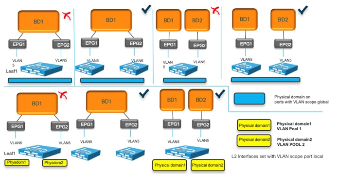
We recommend that you use unique VLANs per EPG within a bridge domain and across leaf switches to be able to scope flooding and BPDUs within the EPG if so desired.
EPGs, Physical and VMM Domains, and VLAN Mapping on a Specific Port (or Port Channel or vPC)
When using an EPG configured with a physical domain you cannot assign more than one VLAN per port to this EPG either using a static port nor using a static leaf switch.
For instance, with physical domains if you have a static binding (static port) for EPG 10 on port 1/10, VLAN 10, you cannot also have another static binding for the same EPG for port 1/10, VLAN 20.
This restriction doesn’t apply to the case where you have a physical domain and a VMM domain on the same EPG with non-overlapping VLANs. For instance, you could have EPG 10 with static binding on port 1/10, VLAN 10 and also the same EPG mapped to a VMM and sending/receiving traffic to/from the EPG 10 port group on the virtualized host using VLAN 20.
This restriction doesn’t apply to the case of multiple VMM domains either. Multiple VMM domains can connect to the same leaf switch if they do not have overlapping VLAN pools on the same port. For more information refer to the following link: https://www.cisco.com/c/en/us/td/docs/dcn/aci/apic/5x/virtualization-guide/cisco-aci-virtualization-guide-51x/Cisco-ACI-Virtualization-Guide-421_chapter_010.html#concept_892ACA4D8A924717A23BF780BC434DD9
For instance, you could have EPG10 configured with VMM domain1 and VMM domain2, and as a result have two port groups on the virtualized host. One port group could be mapped to VLAN 10 and one mapped to VLAN 20, and both port groups send traffic to Cisco ACI on the same port 1/10 for the same EPG. This is a classic design scenario when multiple virtualized hosts are connected to Cisco ACI using an intermediate switch. The Cisco ACI port is typically a vPC.
Table 7 summarizes these points.
Table 7 Allowed configurations with EPGs configured with static binding and/or VMM domain on a port
|
|
Example 1: EPG 10 |
Example 2: EPG 10 |
Example 3: EPG10 |
|||
| Domain |
Physical domain |
Physical domain |
VMM domain 1 |
VMM domain 1 |
VMM domain 2 |
|
| Path |
Static binding port 1/10 |
Static binding port 1/10 |
Static binding port 1/10 |
Port group 1 on vDS 1 sending traffic to port 1/10 |
Port group 1 on vDS 1 sending traffic to port 1/10 |
Port group 2 on vDS 2 sending traffic to port 1/10 |
| VLAN |
VLAN 10 |
VLAN 20 |
VLAN 10 |
Dynamically picked VLAN, e.g. 20 |
Dynamically picked VLAN, e.g. 20 |
Dynamically picked VLAN, e.g. 30 |
| Configuration Allowed/Not Allowed |
Configuration Rejected (not a hardware limitation, just a configuration restriction) |
Valid Configuration |
Valid Configuration |
|||
It is outside the scope of this document to describe the features of microsegmented EPGs in detail. For more information about microsegmented EPGs, refer to the following document:
The following is a list of uSeg EPG configuration and design points to keep in mind:
● The uSeg EPG domain must be configured to match the base EPG domain.
● Base EPGs and uSeg EPGs must be in the same bridge domain and the bridge domain must have an IP address subnet.
● In the case of physical domains, under the uSeg EPG configuration, you need to define on which leaf switch the policies related to the uSeg EPG should be programmed. The configuration is done using the "Static Leafs" option.
● In the case of a VMware vDS VMM domain, "Allow Micro-Segmentation" must be enabled at the base EPG. This automatically configures private VLANs (PVLAN) on the port group for the base EPG and proxy-ARP within the base EPG. If there is an intermediate switch, such as a UCS Fabric interconnect, in-between a Cisco ACI leaf switch and a VMware vDS, PVLAN must be configured at the intermediate switch.
● uSeg EPG is also part of vzAny and supports preferred group, intra EPG isolation, intra EPG contract, and other configurations per EPG.
Internal VLANs on the Leaf Switches: EPGs and Bridge Domains Scale
The scale of EPGs is ˜15,000 fabric-wide. The scale of bridge domains is also ˜15,000 fabric-wide as described in the verified scalability guides:
While the Cisco ACI fabric offers an aggregate capacity of ˜15,000 EPGs and/or bridge domains, on a per-leaf switch basis you need to take into account the fact that VLAN tags are used locally to divide the traffic in different EPGs and different bridge domains. The total number of VLANs used on the switch depends on the number of EPGs and bridge domains; the total count must be under 3960. You can monitor the utilization of these hardware resources from the Operations > Capacity Dashboard > Leaf Capacity.
Because VLANs have local significance, the same VLAN number can be reused on other leaf switches and can be mapped to the same or to a different bridge domain and as a result the fabric-wide scale for EPGs and bridge domains is higher than the per-leaf switch scale.
The per-leaf switch scale numbers also apply when using Cisco ACI Virtual Edge with VXLANs, because leaf switches internally have hardware tables that use VLAN numbers (locally) to keep EPG traffic separate, to map EPGs to bridge domains, and to maintain information about bridge domains.
Assigning Physical Hosts to EPGs
To assign hosts/endpoints to EPGs, you can use one of the following approaches:
● Define the path from Tenant > Application Profiles > Application EPGs > EPG > Static Ports configuration
● Apply the Fabric > Access Policies > Policies > Global > AAEP configuration to the interface (s) and select the Tenant, Application Profile, Application EPG from the AAEP itself.
In either case, you need to specify the domain (a physical domain for physical hosts) for the EPG: Tenant > Application Profiles > Application EPGs > EPG > Domains.
The domain entered in the EPG and the domain applied to the interface from the Fabric > Access Policies > Interfaces must match.
This methodology can be used to assign both physical hosts and virtualized hosts (without VMM integration). For virtualized hosts, you need to match the VLAN information entered in the EPG with the VLAN assigned to port groups in the virtualized host.
Using the Application Profile EPG
You can assign a workload to an EPG as follows:
● Static port: Map an EPG statically to a port and VLAN.
● Static leaf: Map an EPG statically to a VLAN switch-wide on a leaf switch. If you configure EPG mapping to a VLAN switch-wide (using a static leaf switch binding configuration), Cisco ACI configures all leaf switch ports as Layer 2 ports. This configuration is practical, but it has the disadvantage that if the same leaf switch is also a border leaf switch, you cannot configure Layer 3 interfaces because this option changes all the leaf switch ports into trunks. Therefore, if you have a L3Out connection, you must use SVI interfaces.
Note: Use the static leaf configuration only on leaf nodes that are not connected to controllers. Deploying the static leaf configuration on controller-connected nodes is not supported as of release 6.0(2h).
● EPGs can have a mix of mappings: The very same EPG may include static ports as well as VMM domains.
Assigning Hosts to EPGs from the Attachable Access Entity Profile (AAEP)
You can configure which EPG the traffic from a port belongs to based on the VLAN with which it is tagged. This type of configuration is normally performed from the tenant configuration, but it can be tedious and error prone.
An alternative and potentially more efficient way to configure this is to configure the EPG mappings directly from the Attachable Access Entity Profile (AAEP), as described in Figure 59.
You can find more information about the configuration in the following document:
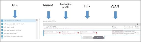
Assigning Virtual Machines to EPGs
Cisco ACI can be integrated with virtualized servers using either EPG static port binding or through a VMM domain:
● With EPG static port configurations (static binding), the VLAN assignment to port groups is static; that is, defined by the administrator.
● When you use a VMM domain, the VLAN allocation is dynamic and maintained by the Cisco APIC. The resolution in this case is also dynamic, so the allocation of VRF, bridge domain, EPG, and other objects on a leaf switch is managed by the Cisco APIC through the discovery of a virtualized host attached to a leaf switch port. This dynamic allocation of resources works if one of the following control plane protocols is in place between the virtualized host and the leaf switch: Cisco Discovery Protocol, LLDP, or OpFlex protocol.
Using the integration with VMware vSphere as an example, with the VMM integration, Cisco APIC uses the VMware vCenter APIs to configure a vDS and coordinates the VLAN configuration on vDS port groups to encapsulate traffic with VLANs.
The VMM integration with VMware vSphere can be done in two different ways:
● By using the API integration between Cisco APIC and VMware vCenter: This integration doesn’t require installing any software nor virtual appliance on the VMware ESXi host. This section focuses on this type of integration.
● By using the API integration between Cisco APIC and VMware vCenter and an optional Cisco software switching component on the ESXi host called Application Virtual Edge (AVE), which at the time of this writing is End of Sale (https://www.cisco.com/c/en/us/products/collateral/cloud-systems-management/application-policy-infrastructure-controller-apic/eol-apic-virtual-edge-pod-pb.html).
This document focuses on the Cisco ACI integration with VMware vCenter with the integration based on APIs, where Cisco ACI creates a VMware vDS on the virtualized servers.
You can find more information about Cisco ACI Virtual Edge at the following links:
With VMM integration, and more specifically in this example with VMM integration with VMware vSphere, Cisco APIC manages the following networking properties on VMware vSphere:
● On VMware vDS: LLDP, CDP, MTU, LACP, ERSPAN, statistics
● On the VMware vDS port groups: VLAN assignment and teaming, and failover on the port groups
VMM integration is based on the definition of a VMM domain. A VMM domain is defined as the virtual machine manager information and the pool of VLANs or multicast addresses for VXLANs that this VMM uses to send traffic to the leaf switches.
With VMM integration in the EPG configuration, you don’t need to enter the exact path where to send/receive traffic to/from the port group of the Virtual Machine. This is automatically resolved by Cisco ACI using LLDP, CDP, OpFlex, and so on.
With VMM integration in the EPG configuration, you don’t need to enter the VLAN to be used to send/receive traffic to/from the port group of the virtual machine. This is automatically programmed by Cisco APIC on the virtualized host.
Because of this, the VLAN pool defined in the VMM domain should be configured as dynamic to allow the Cisco APIC to allocate VLANs to EPGs and port groups as needed.
A VLAN pool can consist of both dynamic and static ranges. The static range may be required if you need to define a static binding to a specific VLAN used by the same virtualized host that is part of a VMM domain.
In summary, when using VMM integration, the configuration of the EPG doesn’t need to include the static port (that is, the reference to the leaf switch and port or the vPC) and VLAN. Instead, you just need to add the VMM domain information to the EPG domain field.
EPGs can have a mix of mappings: the very same EPG may include static ports as well as VMM domains.
The EPG could be mapped to more than one VMM domain and also multiple VMM domains may be sending traffic to Cisco ACI using the same port (or more likely the same virtual port channel) as described in the following document:
The following sections discuss configurations and design considerations for the deployment of Cisco ACI with a virtualized environment and, in particular, with VMware vSphere.
The initial configuration consists of providing Cisco APIC with all the information to connect to the Virtual Machine Manager (in this example VMware vCenter).
The steps to configure the Cisco ACI integration with VMware vSphere are as follows:
● The administrator creates a VMM domain in the Cisco APIC with the IP address and credentials for connecting to VMware vCenter.
● The Cisco APIC connects to VMware vCenter and creates a new vDS under VMware vCenter.
● The VMware vCenter administrator adds the ESXi host to the vDS controlled by the Cisco APIC and assigns the ESXi host ports as uplinks on the vDS. These uplinks must connect to the Cisco ACI leaf switches.
● The Cisco APIC learns to which leaf switch port the hypervisor host is connected using LLDP or Cisco Discovery Protocol.
After this initial configuration you can assign EPGs to the VMM domain and that creates port groups in the virtualized host.
EPG Configuration Workflow with VMM Integration
You can assign a virtual machine workload to an EPG as follows:
● Map an EPG to a VMM domain.
● Set the Resolution and Deployment Immediacy as desired by following the recommendations in the "Resolution Immediacy and Deployment Immediacy Considerations for Virtualized Servers" section. If one vDS EPG is providing management connectivity for VMware vCenter, you should configure Resolution Immediacy as Pre-Provision.
● The Cisco APIC automatically creates VMware vDS port groups in VMware vCenter. The EPG is automatically mapped to port groups. This process provisions the network policy in VMware vCenter.
● The VMware vCenter administrator creates virtual machines and assigns the virtual machine vNIC to port groups (there is one port group per each EPG that has the VMM Domain configured).
● The Cisco APIC learns about the virtual machine placements based on the VMware vCenter events.
For microsegmentation, the configuration steps are as follows:
1. Create a base EPG and map it to a VMM domain.
2. The Cisco APIC automatically creates a VMware vDS port group in VMware vCenter. The EPG is automatically mapped to the port group. This process provisions the network policy in VMware vCenter.
3. The VMware vCenter administrator creates virtual machines and assigns the virtual machine vNIC to the only port group: the base EPG port group. The Cisco APIC learns about the virtual machine placements based on the VMware vCenter events.
4. Create microsegments based on virtual machine attributes to classify the VMs into uSeg EPGs.
For each VMM domain defined in Cisco ACI, the Cisco APIC creates a VMware vDS in the hypervisor. If the user configured two VMM domains with the same VMware vCenter but with different data centers, Cisco APIC creates two vDS instances.
In most cases, a single vDS with multiple port groups provides sufficient isolation. However, in some cases multiple vDSs may be required for administrative reasons.
You can have multiple vDSs on the same VMware ESXi host (either Cisco APIC controlled or static) as long as they use different uplink VMNIC interfaces, and you should define a nonoverlapping range of VLANs for each VMM domain.
You can have vDSs of different types. For instance, one could be a VMware vSphere-created vDS and another could be a VMM-created VMware vDS.
The following are examples of supported deployment scenarios if each vDS uses a different set of uplink VMNICs:
● vDS (unmanaged by Cisco APIC) and vDS (managed by Cisco APIC) on the same host: This is a common scenario for migrating from a deployment other than Cisco ACI to Cisco ACI.
● vDS (managed) and vDS (managed)
Connecting EPGs to External Switches
When connecting Cisco ACI to external switches, preventing a Layer 2 loop is the key design consideration.
The "Loop mitigation features / Spanning Tree Protocol considerations" section describes how STP interacts with Cisco ACI.
This section focuses on the how-to of the connectivity with the goal of reducing the chance of Layer 2 Loops.
You can connect a bridge domain to an external Layer 2 network with either of the following configurations:
● Using the Tenant > Networking > L2Outs configuration
● Using a regular Tenant > Application Profiles > EPG configuration
The two configurations are functionally the same, except that the L2Out configuration is more restrictive to help the user prevent loops due to misconfigurations. With the L2Out configuration, you would define the bridge domain and one external Layer 2 EPG, and only one VLAN per L2Out. The configuration would look more similar to the L3Out in terms of object model.
Because of the fact that the L2Out and the EPG configurations are functionally the same, but the EPG configuration is more flexible and more widely used, this document recommends and focuses on the use of the EPG configuration for Layer 2 external connectivity.
Using EPGs to connect Cisco ACI to External Layer 2 Networks
You need to consider that in Cisco ACI, the bridge domain is the equivalent of the classic VLAN or Layer 2 network. A bridge domain is able to forward Layer 2 multidestination traffic. If multiple encapsulation VLANs are mapped to the same bridge domain using EPGs, broadcast or an unknown unicast or a multicast traffic is forwarded from the EPG where it came from (on a given VLAN) to all the other EPGs of the same bridge domain, which may be configured with the same or different VLANs. A wrong configuration can lead to a Layer 2 loop.
To address this concern, Cisco ACI forwards BPDUs as described in the "BPDU Handling" section. Cisco ACI forwards BPDUs if they are received on a regular EPG. Isolated EPGs don’t forward BPDUs.
Figure 60 provides an example that helps understanding how external Layer 2 networks can be connected to Cisco ACI and how Spanning Tree running in the external network can keep the topology free from loops, as well as how a wrong configuration on the outside network could introduce a loop.
In Figure 60, a bridge domain is configured with two different EPGs (you could call this an application-centric model) and two external switches are connected to two different EPGs within the fabric. In this example, VLANs 10 and 20 from the outside network are stitched together by the Cisco ACI fabric. The Cisco ACI fabric provides Layer 2 bridging for traffic between these two VLANs. These VLANs are in the same flooding domain. From the perspective of the Spanning Tree Protocol, the Cisco ACI fabric floods the BPDUs within the EPG (within the same VLAN ID). When the Cisco ACI leaf switch receives the BPDUs on EPG 1 on VLAN 10, it floods them to all leaf switch ports in EPG 1, VLAN 10, and it does not send the BPDU frames to ports in the other EPGs because they are on different VLANs.
This BPDU forwarding behavior can break the potential loop within the respective EPGs (EPG1 and EPG2, VLAN 10 and VLAN 20), but this doesn’t break a potential loop introduced by bridging VLAN 10 with VLAN 20 by connecting the external switch pairs to each other. You should ensure that VLANs 10 and 20 do not have any physical connections other than the one provided by the Cisco ACI fabric.
You must ensure that the external switches are not directly connected outside the fabric because you are already using the Cisco ACI fabric to provide redundant Layer 2 connectivity between them. We strongly recommend in this case that you enable BPDU guard on the access ports of the external switches to help ensure that any accidental direct physical connections are blocked immediately.
The "Flood in Encapsulation" section describes how you can also configure Cisco ACI to flood multidestination traffic only in the same VLAN as the one that the traffic was received from. With Flood in Encapsulation, the network on VLAN 10 and the network on VLAN 20 would become effectively two separate Layer 2 networks, even if they belong to the same bridge domain.
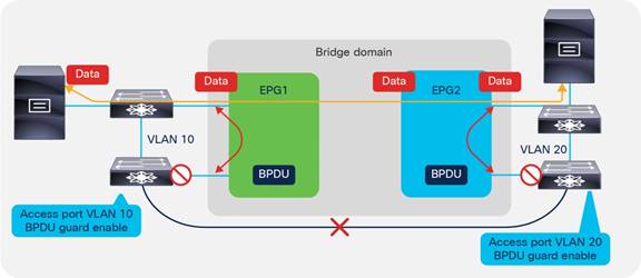
EPG and Fabric Access Configurations for Multiple Spanning Tree
BPDU frames for Per-VLAN Spanning Tree (PVST) and Rapid Per-VLAN Spanning Tree (RPVST) have a VLAN tag. The Cisco ACI leaf switch can identify the EPG on which the BPDUs need to be flooded based on the VLAN tag in the frame.
However, for MST (IEEE 802.1s), BPDU frames do not carry a VLAN tag, and the BPDUs are sent over the native VLAN. Typically, the native VLAN is not used to carry data traffic, and the native VLAN may not be configured for data traffic on the Cisco ACI fabric. As a result, to help ensure that MST BPDUs are flooded to the desired ports, you must create an EPG (this is a regular EPG that you define) for VLAN 1 (or the VLAN used as a native VLAN on the outside network) as the native VLAN to carry the BPDUs. This EPG connects to the external switches that run MST with a static port configuration that uses mode access (802.1p) and vlan-1 as encap. On second generation leaf switches, you can also use the access (untagged) option for the static port configuration in this EPG.
In addition, the administrator must configure the mapping of MST instances to VLANs to define on which VLAN must the MAC address table entries be flushed when a Topology Change Notification (TCN) occurs. As a result of this configuration, when a TCN event occurs on the external Layer 2 network, this TCN reaches the leaf switches and it flushes the local endpoints on the VLANs listed. As a result, these entries are removed from the spine switch-proxy endpoint database. This configuration is performed from Fabric > Access Policies > Policies > Switch > Spanning Tree. You need to apply this configuration to the leaf switches using a policy group: Fabric > Access Policies > Switches > Leaf Switches > Policy Groups > Spanning Tree Policy.
Minimize the scope of Spanning Tree Topology Changes
As part of the Spanning Tree design, you should make sure that Spanning Tree topology change notifications (TCNs) due to changes in the forwarding topology of an external Layer 2 network do not unnecessarily flush the bridge domain endpoints in the Cisco ACI fabric.
When Cisco ACI receives a TCN BPDU on a VLAN in a bridge domain, it flushes all the endpoints associated with this VLAN in that bridge domain.
To avoid clearing endpoints that are directly connected to the Cisco ACI leaf switches, you should use a different VLAN for the local endpoint connectivity and for the connectivity to an external switched network. This approach limits the impact of Spanning Tree TCN events to clearing the endpoints learned on the external switched network.
Using EPGs to Connect Cisco ACI to External Layer 2 Networks Using vPCs
Figure 61 illustrates a better approach for Layer 2 external switches connectivity than the one described in Figure 60:
● Use a vPC to connect to the outside so that there is no blocking port.
● Use LACP on the vPC with LACP suspend individual port enabled.
● Ensure that the external Layer 2 network has Spanning Tree enabled so that if a loop occurs Spanning Tree can help prevent the loop.
● Use MCP.
● If you use one VLAN per EPG and one EPG per bridge domain (network centric model) for Layer 2 external reduces significantly the risk of introducing loops in the bridge domain.
● Use Endpoint Loop Protection with the option to disable learning on the bridge domain if a loop occurs.
● Follow the recommendations described in the "Loop Mitigation Features" section for the details on how to tune the individual features.
● Define the operational sequence of adding a new external Layer 2 network to minimize transient states, which could introduce loops. For instance, create the EPG for external Layer 2 connectivity, set the EPG first with the option "Shutdown EPG" selected, associate the EPG with the policy group type vPC, make sure that the port channel ports are bundled using LACP (that is, in the ports are in the LACP P state), then bring up the EPG by deselecting the "Shutdown EPG" option.
Figure 61 illustrates the fact that to avoid introducing loops, it is considered best practice to connect external switches to Cisco ACI using vPCs and ensure that there is no physical loop outside of the Cisco ACI fabric itself.
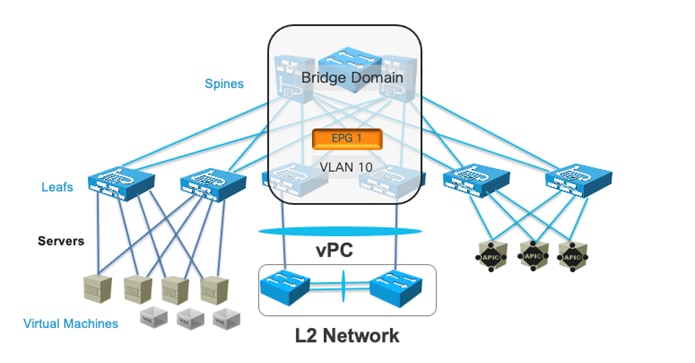
Figure 62 illustrates a topology for Layer 2 external connectivity similar to the one of Figure 61 in that the external networks are connected using vPC, but where the bridge domain has multiple EPGs, just as in Figure 60.
The key difference with the topology of Figure 60 is that external Layer 2 networks are connected using vPCs. They are the same Layer 2 network (that is, the same subnet) because they are bridged together by the Cisco ACI bridge domain, and if you were to connect L2 network 1 and L2 network 2 directly outside of the Cisco ACI fabric there would indeed be a loop.
There are variations to the topology of Figure 62 depending on the design goal:
● You could be using VLAN 10 on both EPG1 and EPG2, so that BPDUs from Spanning Tree could detect a potential loop due to miscabling between L2 Network 1 and L2 Network 2. This design choice depends on whether it makes sense to merge the Spanning Tree topology of Network 1 with Network 2, and having a single root for both networks. If you can guarantee that Network 1 and Network 2 are not connected to each other outside of Cisco ACI, there would be no requirement to use the same VLAN.
● You could use different VLANs in EPG1 and EPG2 as in the picture together with flood in encapsulation. This would keep Layer 2 Network 1 and Layer 2 Network 2 separate while merging them under the same bridge domain object. This could be useful if there is no need to exchange Layer 2 traffic between servers of Layer 2 network 1 and servers of Layer 2 Network 2. Servers of Network 1 and Network 2 would still be in the same subnet (Cisco ACI would do proxy ARP).
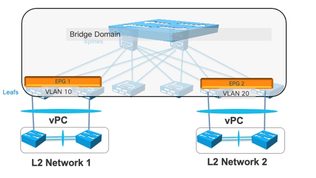
This section includes some features that are useful either for operational reasons, or that are important to know for completeness in the design document.
Starting from Cisco ACI, 4.0 you can shut down an EPG. This configuration can be useful in many situations where the admin desires to prevent traffic from a given EPG from being received by the fabric, assigned to the bridge domain, and so on. Before Cisco ACI 4.0, this required removing the EPG configuration or removing the VMM/physical domain configuration and the static port or leaf switch configuration.
When the administrator shuts down an EPG, the VLAN configuration related to that EPG is removed from the leaf switch as well as the policy CAM programming. Clearly, if more than one EPG are on a given bridge domain, shutting down the EPG doesn’t remove the bridge domain gateway from the leaf switches if there are other EPGs that are not shut down.
The configuration is located under Tenant > Application Profiles > EPG > Shutdown EPG.
In addition to the main functionalities of mapping traffic to the bridge domain based on incoming port and VLAN, the EPG also includes some configurations that are more related to routing functions.
One of them is the ability to define a static route as a /32. This is not really a static route. It is primarily a way to map an IP address that doesn’t belong to the bridge domain subnet to another IP address that instead is in the bridge domain subnet.
This is configured from the Subnet field under the EPG with a "Type Behind Subnet" of type "EP Reachability" and a next-hop IP address.
If you really require configuring proper static routing, you should use a L3Out configuration instead.
Another routing feature that depends on the EPG configuration is proxy ARP. Cisco ACI enables automatically proxy ARP when you configure flood in encapsulation and when you configure microsegmented EPGs (uSeg EPGs).
ARP from a uSeg EPG to a regular EPG doesn’t require Cisco ACI to answer with proxy ARP, nor does ARP from a regular EPG to a uSeg EPG. On the other hand, an ARP request from a server on a uSeg EPG to a server on the base EPG or to another uSeg EPG requires Cisco ACI to answer with proxy ARP.
If you enable intra-EPG isolation, Cisco ACI displays the option "Forwarding Control" to enable proxy ARP.
Contracts Design Considerations
A contract is a policy construct used to define communication between EPGs or ESGs. Without a contract between EPGs or ESGs, no communication is possible between those EPGs/ESGs, unless the VRF instance is configured as unenforced. Within an EPG or an ESG, a contract is not required to allow communication, although communication can be prevented with microsegmentation features or with intra-EPG or intra-ESG contracts. Figure 63 shows the relationship between EPGs/ESGs and contracts.
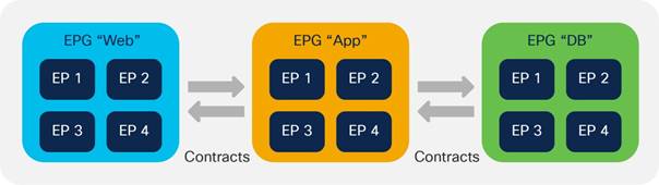
An EPG/ESG provides or consumes a contract, or provides and consumes a contract. For instance, the App EPG in the example in Figure 63 provides a contract that the App Web consumes, and consumes a contract that the DB EPG provides.
Note You can use a contract between EPGs or between ESGs, but not between an EPG and an ESG. You can use a contract between an external EPG and an ESG.
While this section provides examples based on EPGs, all the concepts explained in this section equally apply to the use of ESGs.
Defining which side is the provider and which one is the consumer of a given contract allows establishing a direction of the contract for where to apply ACL filtering. For instance, if the EPG Web is a consumer of the contract provided by the EPG App, you may want to define a filter that allows HTTP port 80 as a destination in the consumer-to-provider direction and as a source in the provider-to-consumer direction.
If, instead, you had defined the Web EPG as the provider and the App EPG as the consumer of the contract, you would define the same filters in the opposite direction. That is, you would allow HTTP port 80 as the destination in the provider-to-consumer direction and as the source in the consumer-to-provider direction.
In normal designs, you do not need to define more than one contract between any EPG pair. If there is a need to add more filtering rules to the same EPG pair, this can be achieved by adding more subjects to the same contract.
For more information about contracts, refer to the following white paper:
Security Contracts are ACLs Without IP Addresses
You can think of security contracts as ACLs between EPGs or ESGs. As Figure 64 illustrates, the forwarding between endpoints is based on routing and switching as defined by the configuration of VRF instances and bridge domains. Whether the endpoints in the EPGs or ESGs can communicate depends on the filtering rules defined by the contracts.
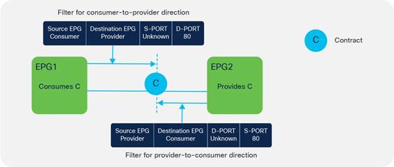
Note: Contracts can also control more than just the filtering. If contracts are used between EPGs in different VRF instances, they are also used to define the VRF route-leaking configuration.
A filter is a rule specifying fields such as the TCP port and protocol type, and it is referenced within a contract to define the communication allowed between EPGs or ESGs in the fabric.
A filter contains one or more filter entries that specify the rule. The example in Figure 65 shows how filters and filter entries are configured in the Cisco APIC GUI.
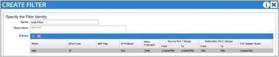
A subject is a construct contained within a contract and typically references a filter. For example, the contract Web might contain a subject named Web-Subj that references a filter named Web-Filter.
Permit, Deny, Redirect, and Copy
The action associated with each filter is either permit or deny. The subject can also be associated with a service graph configured for PBR (redirect) or copy. These options give the flexibility to define contracts where traffic can be permitted, dropped, or redirected, or provide a copy similar to what SPAN does, but for a specific contract.
Refer to the "Contracts and Filtering Rule Priority" section to understand which rule wins in case of multiple matching rules.
Concept of Direction in Contracts
Filter rules have a direction, similar to ACLs in a traditional router. ACLs are normally applied to router interfaces. In the case of Cisco ACI, contracts differ from classic ACLs in the following ways:
● The interface to which they are applied is the connection line of two EPG/ESGs.
● The directions in which filters are applied are the consumer-to-provider and the provider-to-consumer directions.
● Contracts do not include IP addresses because traffic is filtered based on EPG/ESGs (or source group or class ID, which are synonymous).
Understanding the Bidirectional and Reverse Filter Options
When you create a contract, two options are typically selected by default:
● Apply Both Directions
● Reverse Filter Ports
The Reverse Filter Ports option is available only if the Apply Both Directions option is selected (Figure 66).
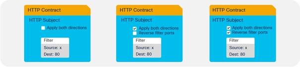
An example clarifies the meaning of these options. If you require EPG-A (the consumer) to consume web services from port 80 on EPG-B (the provider), you must create a contract that allows source Layer 4 port "any" ("unspecified" in Cisco ACI terminology) to talk to destination Layer 4 port 80. You must then consume the contract from EPG-A and provide the same contract from the EPG-B (Figure 67).
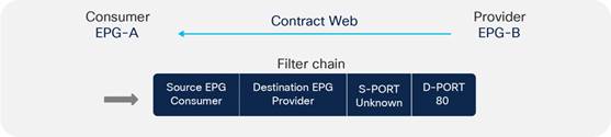
The effect of enabling the Apply Both Directions option is to program two TCAM entries: one that allows source port "unspecified" to talk to destination port 80 in the consumer-to-provider direction, and one for the provider-to-consumer direction that allows source port "unspecified" to talk to destination port 80 (Figure 68).
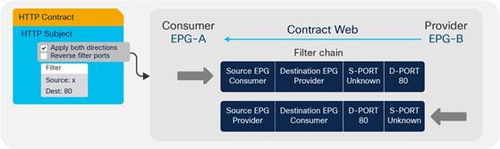
As you can see, this configuration is not useful because the provider (server) would generate traffic from port 80 and not to port 80.
If you enable the option Reverse Filter Ports, Cisco ACI reverses the source and destination ports on the second TCAM entry, thus installing an entry that allows traffic from the provider to the consumer from Layer 4 port 80 to destination port "unspecified" (Figure 69).
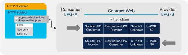
Cisco ACI by default selects both options: Apply Both Directions and Reverse Filter Ports.
Configuring a Stateful Contract
The Stateful option allows TCP packets from provider to consumer only if the ACK flag is set. This option is disabled by default. We recommend that you enable the Stateful option in the TCP filter entries for better security unless Enable Policy Compression is required. The policy compression can’t be applied if the Stateful option is enabled.
Figure 70 shows how to enable the stateful option.
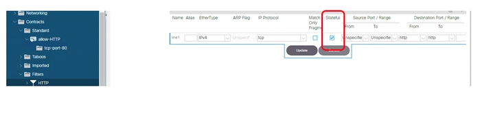
With this option enabled, a bidirectional contract gets automatically programmed with a permit entry for the specified ports for the consumer-to-provider direction and with a permit entry from the specified port and with the ACK bit set for the provider-to-consumer direction as illustrated in Table 8. Table 8 shows the policy-CAM programming for a contract with a filter for port 80 with the stateful option selected.
Table 8 Policy CAM programming for contracts with stateful filters
| Source class |
Source Port |
Dest class |
Destination Port |
Flag |
Action |
| Consumer |
* |
Provider |
80 |
* |
Permit |
| Provider |
80 |
Consumer |
* |
ACK |
Permit |
Configuring a Single Contract Between EPG/ESGs
An alternative method for configuring filtering rules on a contract is to manually create filters in both directions: consumer-to-provider and provider-to-consumer.
With this configuration approach, you do not use Apply Both Directions nor Reverse Filter Ports, as you can see in Figure 71.
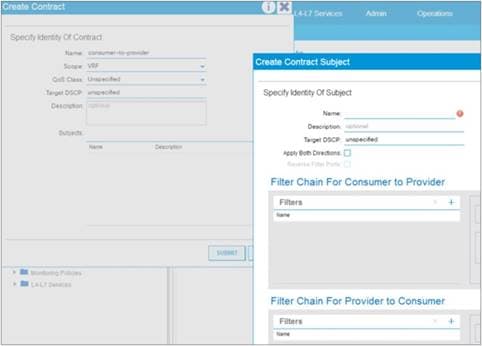
The configuration of the contract in this case consists of entering filter rules for each direction of the contract. As you can see from this example, more than one contract between any two EPG/ESGs is not generally required. If you need to add filtering rules between EPG/ESGs, you can simply add more subjects to the contract, and you can choose whether the subject is bidirectional or unidirectional.
If you configure bidirectional subject Cisco ACI programs automatically, the reverse filter port rule and with Cisco Nexus 9300-EX or later, this can be optimized to consume only one policy CAM entry by using compression. For more information about policy compression, refer to the "Policy CAM compression" section. If you configure unidirectional subject rules, you can define filter ports for the consumer-to-provider direction and the provider-to-consumer direction independently.
The scope of a contract defines the EPGs to which the contract can be applied:
● VRF: EPGs associated with the same VRF instance can use this contract.
● Application profile: EPGs in the same application profile can use this contract.
● Tenant: EPGs in the same tenant can use this contract even if the EPGs are in different VRF instances.
● Global: EPGs throughout the fabric can use this contract.
Contracts and Filters in the Common Tenant
As described in the "ACI objects design considerations" section, in Cisco ACI, the common tenant provides resources that are visible and can be used from other tenants. For instance, instead of configuring multiple times the same filter in every tenant, you can define the filter once in the common tenant and use it from all the other tenants.
Defining contracts in tenant common can be convenient for operational reasons and combined with compression it helps reduce policy-CAM utilization, but it is important to understand the scope of contracts first in order to avoid making configurations that do not reflect the original connectivity requirements.
Setting the Contract Scope Correctly
Although it is convenient to use filters from the common tenant, it is not always a good idea to use contracts from the common tenant for the following reasons:
● The name used for contracts in the common tenant should be unique across all tenants. If a tenant is using a contract called for instance "web-to-app" from the common tenant (common/web-to-app), and you define a new contract with the same name inside of the tenant itself (mytenant/web-to-app), Cisco ACI will change the EPG relations that were previously associated with common/web-to-app to be associated to the locally defined contract mytenant/web-to-app.
● If multiple tenants provide and consume the same contract from the common tenant, you are effectively allowing communication across the EPGs of different tenants if the contract scope is set to Global.
For instance, imagine that in the common tenant you have a contract called web-to-app and you want to use it in tenant A to allow the EPGA-web of tenant A to talk to the EPGA-app of tenant A. Imagine that you also want to allow the EPGB-web of tenant B to talk to EPGB-app of tenant B. If you configure EPGX-app in both tenants to provide the contract web-to-app and you configure EPGX-web of both tenants to consume the contract you are also enabling EPGA-web of tenant A to talk to EPGB-app of tenant B.
This is by design, because you are telling Cisco ACI that EPGs in both tenants are providing and consuming the same contract.
To implement a design where the web EPG talks to the app EPG of its own tenant, you can use one of the following options:
● Configure the contract web-to-app in each individual tenant.
● Define contracts from the common tenant and set the scope of the contract correctly at the time of creation. For example, set the contract scope in the common tenant to Tenant. Cisco ACI will then scope the contract to each tenant where it would be used, as if the contract had been defined in the individual tenant.
Saving Policy-CAM Space with Compression
If you understand how to set the scope correctly, then re-using contracts from tenant common in different tenants could be a good idea if combined with compression to reduce the policy-CAM utilization.
Imagine that you have two tenants: TenantA with EPGA-web and EPGA-app and TenantB with EPGB-web and EPGB-app. Both of them are using a contract web-to-app with filter ABC from tenant common, and the contract scope is "tenant".
Instead of replicating the same filter multiple times in the policy-cam per tenant, Cisco ACI can program:
● EPGA-web to EPGA-app to reference filter ABC
● EPGB-web to EPGB-app to reference filter ABC
The above configuration is not sufficient for compression. For the above to happen, there are a few more conditions to be met: in each tenant there must be at least one more EPG providing the same contract and the condition for compression must be met per leaf switch. This means that each Cisco ACI leaf switch evaluates the EPGs and Tenants that are locally present on the leaf switch itself to optimize the policy-CAM programming.
Pros and Cons of using Contracts from Tenant Common
In summary if you configure contracts in tenant common, you configure the contract scope correctly, and you configure compression, you can reduce the policy-CAM utilization by re-using the contract in multiple tenants as well as within the tenant.
While this saves policy-CAM space, putting all contracts in tenant common can also create more control plane load on a single shard compared to spreading contracts in multiple tenants, which equals spreading the control plane load across multiple Cisco APIC shards. As such, you should keep the number of contracts within the verified scalability limits and gauge the pros and cons of policy-CAM space saving versus Cisco APIC control plane scale.
Unenforced VRF Instances, Preferred Groups, vzAny
In certain deployments, all EPG/ESGs associated with a VRF instance may need to be able to communicate freely. In this case, you could configure the VRF instance with which they are associated as "unenforced." This approach works, but then it will be more difficult, later on, to add contracts.
You can also use a VRF instance as "enforced," and use the preferred groups feature. In this case, you need to organize the EPGs into two groups:
● EPG/ESG members of the preferred group: The endpoints in these EPG/ESGs can communicate without contracts even if they are in different EPGs. If one of two endpoints that need to communicate is part of the preferred group and the other is not, a contract is required.
● EPG/ESGs that are not in the preferred group: These are regular EPG/ESGs.
Another approach consists in configuring a contract that permits all traffic that is applied to all the EPG/ESGs in the same VRF, using vzAny.
vzAny is a special object that represents all EPG/ESGs associated with a given VRF instance, including the Layer 3 external EPG. This configuration object can be found in the Cisco ACI GUI in Networking > VRFs > VRF-name > EPG Collection for VRF.
This concept is useful when a configuration has contract rules that are common across all the EPG/ESGs under the same VRF instance. In this case, you can place the rules that are common across the VRF instance into a contract associated with vzAny.
When using vzAny, you must understand how vzAny interacts with VRF route leaking and with L3Out.
One common use of the vzAny object relates to consumption of the same set of shared services provided by an EPG in a different VRF instance. vzAny can only be a consumer of shared services, not a provider.
For more details about vzAny restrictions, refer to the following document:
An additional consideration when using vzAny is the fact that it includes the Layer 3 external connection of the VRF. If vzAny is consuming a contract provided by an EPG within a different VRF, the subnets defined under this EPG may be announced from the L3Out interface. For example, if you have vzAny from VRF1 consuming a contract provided by an EPG from a different VRF (VRF2), the subnets of VRF1 that are marked as public will be announced through the L3Out interface of VRF2.
When using ESGs, VRF instance sharing works differently than with EPGs. With ESGs there is a dedicated configuration to define which routes are leaked to which VRF instance, and as a result there is no need to configure subnets under the ESG (nor under the EPG).
Contracts and Filtering Rule Priorities
When using contracts that include a combination of EPG-to-EPG contracts, with EPGs that may be part of preferred groups or vzAny contracts, you must understand the relative priority of the filtering rules that are programmed in the policy CAM to understand the filtering behavior.
The relative priority of the rules that are programmed in the policy CAM are as follows:
● Filtering rules for contracts between specific EPG/ESGs have priority 7.
● Filtering rules for contracts defined for vzAny-to-vzAny have priority 17 if configured with a filter with an EtherType such as IP or Protocol, and source and destination ports that can be any.
● Preferred group entries that disallow non-preferred-group EPG/ESGs to any, have priorities 18 and 19.
● The implicit permit for preferred group members is implemented as any-to-any permit, with priority 20.
● vzAny configured to provide and consume a contract with a filter such as common/default (also referred to as an any-any-default-permit) is programmed with priority 21.
● The implicit deny has priority 21.
Rules with a lower priority number win over rules with a higher numerical value.
Specific EPG-to-EPG or ESG-to-ESG contracts have priority 7, hence they win over contracts defined, for instance, with vzAny because it is considered less specific.
Among filtering rules with the same priority, the following applies:
● Within the same priority, deny wins over permit and redirect.
● Between redirect and permit, the more specific filter rule (in terms of protocol and port) wins over the less specific.
● Between redirect and permit, if the filter rules are same, redirect wins. If the filter rules have overlapping ports and have the same priority, the priority is not deterministic. Between permit and redirect actions, you should not have overlapping rules with the same priority to avoid indeterministic results.
When entering a filter with a deny action, you can specify the priority of the filter rule:
● Default value: The same as the priority would be, in case there is permit for the same EPG pair
● Lowest priority: Corresponding to vzAny-to-vzAny rules (priority 17)
● Medium priority: Corresponding to vzAny-to-EPG rules (priority 13)
● Highest priority: Same priority as EPG-to-EPG rules (priority 7)
Depending on the leaf switch hardware, Cisco ACI offers many optimizations to either allocate more policy CAM space or to reduce the policy CAM consumption:
● Cisco ACI leaf switches can be configured for policy-CAM-intensive profiles.
● Range operations use one entry only in TCAM.
● Bidirectional subjects take one entry.
● Filters can be reused with an indirection feature, at the cost of granularity of statistics.
The compression feature can be divided into two main optimizations:
● Ability to look up the same filter entry from each direction of the traffic, hence making bidirectional contracts use half of the entries in the policy CAM. This optimization is available on Cisco Nexus 9300-EX or later.
● Ability to reuse the same filter across multiple EPG/ESG pairs in the contract. This optimization is available on Cisco Nexus 9300-FX or later.
The two features are enabled as a result of choosing the "Enable Policy Compression" option in the filter configuration in a contract subject.
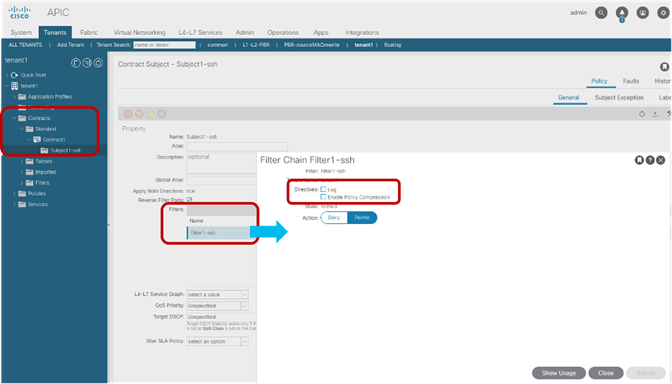
The ability to reuse the same filter is a policy CAM indirection feature where a portion of the TCAM (first-stage TCAM) is used to program the EPG pairs and the link to the entry in the second-stage TCAM that is programmed with the filter entries. If more than one EPG pair requires the same filter, the filter can be programmed in the first-stage TCAM and point to the same filter entry in the second-stage TCAM.
With Cisco Nexus 9300-FX or later hardware, when you can enable "Enable Policy compression" on the filter in a contract subject this enables both the bidirectional optimization and, if the scale profile you chose allows it, policy CAM indirection.
Whether a leaf switch does policy CAM indirection depends on the profile you chose:
● Cisco Nexus 9300-FX can do policy CAM indirection with the default profile, IPv4 scale profile, and High Dual Stack profile.
● Cisco Nexus 9300-FX2 can do policy CAM indirection with the default profile and IPv4 scale profile, but not with the high dual stack profile.
You can find more information about policy CAM compression at the following link:
Resolution and Deployment Immediacy of VRF Instances, Bridge Domains, EPGs, and Contracts
Cisco ACI optimizes the use of hardware and software resources by programming the hardware with VRF instances, bridge domains, SVIs, pervasive routes, EPGs, and contracts only if endpoints are present on a leaf switch that is associated with these.
Cisco ACI programs the VRF and bridge domain SVI pervasive gateway on all the leaf switches that have endpoints for the EPG (and associated bridge domain).
On the other leaf switches where there is no local endpoint for the EPG, Cisco ACI programs a pervasive route for the bridge domain subnet only if there is a local EPG configuration with a contract with this EPG (and hence the associated bridge domain). The pervasive route for the bridge domain subnet points to the spine-proxy IP address.
There are two configurable options to define when and if the VRF, bridge domain, SVI pervasive gateway, and so on are programmed on a leaf switch:
● Resolution Immediacy: This option controls when VRF, bridge domains, and SVIs are pushed to the leaf switches.
● Deployment Immediacy: This option controls when contracts are programmed in the hardware.
Resolution and Deployment Immediacy are configuration options that are configured when an EPG is associated with a physical domain or a VMM domain. A domain represents either a set of VLANs mapped to a set of leaf switches and associated ports (physical domain) or a VMM vDS for a given data center (VMM domain).
They can be configured as follows:
● For physical domains: You can set the deployment immediacy as part of the static port (static binding) configuration. In older releases, the resolution and deployment immediacy option may have been visible as part of the assignment of the physical domain to an EPG, but that configuration doesn’t take effect because resolution immediacy is not applicable to physical domains and deployment immediacy depends on the static port configuration.
● For VMM domains: Both resolution and deployment immediacy are configurable when applying the domain to the EPG.
With ESGs, the resolution and deployment immediacy work slightly differently compared to EPGs. With ESGs, all bridge domain subnets are deployed on all leaf switches with the VRF instance when an ESG is associated to the VRF instance.
With EPGs, based on contracts between EPGs, bridge domain subnets are deployed on other leaf switches in addition to switches with the bridge domain SVIs. This is because Cisco APIC can tell that endpoints need to talk to someone in the other subnet based on the contract.
With ESGs, even without a contract, endpoints may need to talk to someone in another subnet because an ESG can span across multiple bridge domains, and this is why bridge domain subnets are deployed on all switches where the VRF instance is present.
With ESGs the deployment is not configurable and it is always on-demand: if there are endpoints discovered in the ESG, the contract gets programmed, once the contract is removed, the contracts are kept up until a timer expires. This timer is the longer bounce timer in the endpoint retention policy of the bridge domain and the VRF.
The following sections focus on the resolution and deployment immediacy for EPGs.
EPG Resolution Immediacy and Deployment Immediacy Options
The options for Resolution Immediacy (that is, for programming of the VRF, bridge domain, and SVI) are as follows:
● Pre-Provision: This option means that the VRF, bridge domain, SVI, and EPG VLAN mappings are configured on the leaf switches based on where the domain (or to be more precise, the attachable access entity profile) is mapped within the fabric access configuration. If EPG1 is associated with VMM domain 1, the bridge domain and the VRF to which EPG1 refers are instantiated on all the leaf switches where the VMM domain is configured.
● Immediate: This option means that the VRF, bridge domain, SVI, and EPG VLAN mappings are configured on a leaf switch as soon as a Cisco APIC VMM virtual switch is associated with a hypervisor and VMnic connected to this leaf switch. A discovery protocol such as Cisco Discovery Protocol and LLDP (or the OpFlex protocol) is used to form the adjacency and discover to which leaf switch the virtualized host is attached. If an EPG is associated with a VMM domain, the bridge domain and the VRF to which this EPG refers to are instantiated on all leaf switches where Cisco ACI leaf switches have discovered the host.
● On-Demand: This option means that the VRF, bridge domain, SVI, and EPG VLAN mappings are configured on a leaf switch only when a virtual switch managed by the Cisco APIC is associated with a hypervisor and a VMNIC connected to this leaf switch, and at least one virtual machine on the host is connected to a port group (and as a result connected to an EPG) that is using this physical NIC (VMNIC) as uplink.
The options for Deployment Immediacy (that is, for programming of the policy CAM) are as follows:
● Immediate: The policy CAM is programmed on the leaf switch as soon as the policy is resolved to the leaf switch (see the discussion of Resolution Immediacy, above) regardless of whether the virtual machine on the virtualized host has sent traffic.
● On-Demand: The policy CAM is programmed as soon as first dataplane packet reaches the switch.
Table 9 illustrates the result of the various configuration options depending on the configuration event. For instance, if the Resolution is set to Immediate and the Deployment is set to On-Demand, the VRF, bridge domain and SVIs are programmed on the leaf switch where the host is connected when the host is discovered using CDP, whereas the policy CAM is programmed when the virtual machine sends traffic.
Table 9 Resolution and Deployment Immediacy Results based on Immediacy Configurations and Events
|
|
Resolution |
Pre-Provision |
Immediate |
On-Demand |
|||||||||
|
|
Deployment |
On-Demand |
Immediate |
On-Demand |
Immediate |
On-Demand |
Immediate |
||||||
| Hardware resource |
|
VRF, bridge domain, and SVI |
Policy CAM |
VRF, bridge domain, and SVI |
Policy CAM |
VRF, bridge domain, and SVI |
Policy CAM |
VRF, bridge domain, and SVI |
Policy CAM |
VRF, bridge domain, and SVI |
Policy CAM |
VRF, bridge domain, and SVI |
Policy CAM |
| Event |
Domain associated to EPG |
On leaf switches where AEP and domain are present |
|
On leaf switches where AEP and domain are present |
On leaf switches where AEP and domain are present |
|
|
|
|
|
|
|
|
| Host discovered on leaf switch through Cisco Discovery Protocol |
Same as above |
|
Same as above |
Same as above |
On leaf switch where host is connected |
|
On leaf switch where host is connected |
On leaf switch where host is connected |
|
|
|
|
|
| Virtual machine associated with port group |
Same as above |
|
Same as above |
Same as above |
Same as above |
|
Same as above |
Same as above |
On leaf switch where virtual machine is associated with EPG |
|
On leaf switch where virtual machine is associated with EPG |
On leaf switch where virtual machine is associated with EPG |
|
| Virtual machine sending traffic |
Same as above |
On leaf switch where virtual machine sends traffic |
Same as above |
Same as above |
Same as above |
On leaf switch where virtual machine sends traffic |
Same as above |
Same as above |
Same as above |
On leaf switch where virtual machine sends traffic |
Same as above |
Same as above |
|
EPG Resolution Immediacy and Deployment Immediacy Considerations for Virtualized Servers
The use of the On-Demand option saves hardware resources when deploying servers, especially when the servers are virtualized and integrated using the VMM domain.
The On-Demand option is compatible with live migration of Virtual Machines and requires coordination between Cisco APIC and the VMM. One caveat to using this option with virtualized environments is if all the Cisco APICs in a cluster are down.
If all the Cisco APICs in a cluster are down, live migration of a virtual machine from one virtual host connected to one leaf switch to another virtual host connected to a different leaf switch may occur, but the virtual machine may not have connectivity on the destination leaf switch. An example of this situation is if a virtual machine moves from a leaf switch where the VRF, bridge domain, EPG, and contracts were instantiated to a leaf switch where these objects have not yet been pushed. The Cisco APIC must be informed by the VMM about the move to configure the VRF, bridge domain, and EPG on the destination leaf switch. If no Cisco APIC is present due to multiple failures, if the On-Demand option is enabled, and if no other virtual machine was already connected to the same EPG on the destination leaf switch, the VRF, bridge domain, and EPG cannot be configured on this leaf switch. In most deployments, the advantages of On-Demand option for resource optimization outweigh the risk of live migration of virtual machines during the absence of all Cisco APICs.
Some special considerations apply for the following scenarios:
● When the virtualized hosts management connectivity uses vDS port groups created using EPGs from Cisco ACI. This is the case when the management interface of a virtualized host is connected to the Cisco ACI fabric leaf switch. For this you can choose to use the Pre-Provision option for Resolution Immediacy, as described in the Cisco ACI Fundamentals document (https://www.cisco.com/c/en/us/td/docs/dcn/aci/apic/5x/aci-fundamentals/cisco-aci-fundamentals-51x/m_vmm-domains.html#concept_EF87ADDAD4EF47BDA741EC6EFDAECBBD): "This helps the situation where management traffic for hypervisors/virtual machine controllers are also using the virtual switch associated to Cisco APIC VMM domain (VMM switch)". Deploying a VMM policy on a Cisco ACI leaf switch requires Cisco APIC to collect CDP/LLDP information from both hypervisors using a virtual machine controller and Cisco ACI leaf switches. If the virtual machine controller uses the same VMM switch to communicate with its hypervisors or even the Cisco APIC, the CDP/LLDP information can never be collected because the policy required for virtual machine controller/hypervisor management traffic is not deployed yet.
● Resolution and Deployment immediacy work slightly differently on uSeg EPGs and base EPGs compared to regular EPGs, and this also depends on the domain type. For more information, refer to the following white paper: https://www.cisco.com/c/en/us/solutions/collateral/data-center-virtualization/application-centric-infrastructure/white-paper-c11-743951.html#Microsegmentation
Endpoint Learning Considerations
The endpoint learning mechanisms implemented by Cisco ACI are fundamental to the way Cisco ACI does routing and can be used to optimize traffic forwarding and policy (filtering) enforcement.
Cisco ACI implements an endpoint database that holds the information about the MAC, IPv4 (/32), and IPv6 (/128) addresses of all endpoints and the leaf switch/VTEP on which they are located. This information also exists in hardware in the spine switches (referred to as the spine switch-proxy function).
The endpoint information is necessary to build the spine proxy table in the spine switches and more in general it is necessary to route traffic. In addition to this, the endpoint database is useful for day 2 operations, troubleshooting.
Local Endpoint Learning on the Leaf Switches
Cisco ACI leaf switches learn MAC and IP addresses and update the spine switches through COOP.
MAC address learning occurs regardless of the bridge domain configuration. IP address learning instead happens only when the unicast routing option is enabled in the bridge domain Layer 3 configuration. If routing is disabled under the bridge domain:
● Cisco ACI learns the MAC addresses of the endpoints
● Cisco ACI floods ARP requests (regardless of whether ARP flooding is selected).
If routing is enabled under bridge domain:
● Cisco ACI learns MAC addresses for Layer 2 traffic (this happens with or without unicast routing).
● Cisco ACI learns MAC and IP addresses for Layer 3 traffic
● You can configure the bridge domain for ARP to be handled in a way that removes flooding. See the "ARP flooding" section.
We do not recommend it, but you can have unicast routing enabled without having a default gateway (subnet) configured.
MAC-to-VTEP mapping information in the spine switch is used only for:
● Handling unknown DMAC unicast if hardware-proxy is enabled.
IP-to-VTEP mapping information in the spine switch is used for:
● Handling ARP if ARP flooding is set to disabled and if the leaf switch doesn’t find a /32 hit for the target IP address.
● Handling routing when the leaf switch is not aware yet of the destination IP host address, but the destination IP address belongs to a subnet defined in the Cisco ACI fabric, or when the destination does not match the longest-prefix-match (LPM) table for external prefixes. The leaf switch is configured to send unknown destination IP address traffic to the spine switch-proxy node by installing a subnet route for the bridge domain on the leaf switch and pointing to the spine switch-proxy TEP for this bridge domain subnet.
You can explore the content of the endpoint database by opening the GUI to Fabric > Inventory > Spine > Protocols, COOP > End Point Database.
You can verify the endpoint learning in Cisco ACI by viewing the Client Endpoints field on the EPG Operational tab.
The learning source field will typically display one of the following learning source types:
● vmm: This value is learned from a VMM, such as VMware vCenter or SCVMM. This is not an indication of an entry learned through the dataplane. Instead, it indicates that the VMM has communicated to the Cisco APIC the location of the virtual machine endpoint. Depending on the Resolution and Deployment Immediacy settings that you configured, this may have triggered the instantiation of the VRF, bridge domain, EPG, and contract on the leaf switch where this virtual machine is active.
● learn: The information is from ARP or data-plane forwarding.
● vmm, learn: This means that both the VMM and the dataplane (both real dataplane and ARP) provided this entry information.
● static: The information is manually entered.
● static, learn: The information is manually entered, plus the entry is learned in the dataplane.
Cisco ACI offers two similar configurations related to limiting the dataplane learning of endpoints’ IP addresses to local subnets: per-BD Limit IP Learning To Subnet and Global Enforce Subnet Check.
Enforce Subnet Check ensures that Cisco ACI learns endpoints whose IP addresses belong to the bridge domain subnet. Enforce Subnet Check also ensures that leaf switches learn remote IP address entries whose IP addresses belong to the VRF with which they are associated. This prevents the learning of local and remote IP addresses that are not configured as subnets on the bridge domains of the VRF. In addition, Enforce Subnet Check is implemented in the hardware.
This option is under System Settings > Fabric Wide Settings. For more information, refer to the following document:
Enabling Enforce Subnet Check clears all of the remote entries and prevents learning remote entries for a short amount of time. The entries in the spine-proxy are not cleared, hence traffic forwarding keeps working even during the configuration change.
Note: While no disruption is expected when enabling Enforce Subnet Check, there is the possibility that a given network is working with traffic from subnets that do not belong to the VRF. If this is the case, enabling this feature will cause interruption of these traffic flows.
Enforce Subnet Check requires second generation leaf switches.
Using the Limit IP Learning to Subnet option at the bridge domain level helps ensure that only endpoints that belong to the bridge domain subnet are learned. Global Enforce Subnet Check is superior to Limit IP Learning to Subnet because it also prevents learning of remote endpoint IP addresses whose subnet doesn’t belong to the VRF and it eliminates the need for the Limit IP Learning to Subnet.
Before Cisco ACI 3.0, if this option was enabled on a bridge domain that was already configured for unicast routing, Cisco ACI would flush all the endpoints whose IP address had been learned on the bridge domain, and it would pause learning for two minutes. Starting from Cisco ACI 3.0, endpoint IP addresses that belong to the subnet are not flushed and learning is not paused.
Limit IP Learning to Subnet works on both first generation leaf switches and second generation leaf switches.
If no activity occurs on an endpoint, the endpoint information is aged out dynamically based on the setting of an idle timer. The default timer for the table that holds the host information on the leaf switches is 900 seconds. If no activity is detected from a local host after 75 percent of the idle timer value has elapsed, the fabric checks whether the endpoint is still alive by sending a probe to it. If the endpoint does not actively send traffic for the configured idle time interval, the Cisco ACI leaf switch notifies both the object store and the spine switches using COOP to indicate that the endpoint should be deleted.
Leaf switches also have a cache for remote entries that have been programmed as a result of active conversations. The purpose of this cache is to store entries for active conversations with a given remote MAC or IP address, so if there are no active conversations with this MAC or IP address, the associated entries are removed after the expiration of the timer (which is 300 seconds by default).
Note: You can tune this behavior by changing the Endpoint Retention Policy setting for the bridge domain.
For Cisco ACI to be able to maintain an updated table of endpoints, you should have the endpoints learned using the IP address (that is, they are not just considered to be Layer 2 hosts) and have a subnet configured under a bridge domain.
A bridge domain can learn endpoint information with unicast routing enabled and without any subnet. However, if a subnet is configured, the bridge domain can send an ARP request for the endpoint whose endpoint retention policy is about to expire, to see if it is still connected to the fabric.
It is good practice to make sure that the Cisco ACI configuration ensures that up-to-date endpoint information is both in the database as well as in the hardware tables.
This is even more important when using the hardware-proxy option in the bridge domain configuration. Hence, if the bridge domain is not configured for unicast routing, make sure to tune the endpoint retention policy for the Layer 2 entries idle timeout to be longer than the ARP cache timeout on the servers.
Endpoint Aging with Multiple IP Addresses for the Same MAC Address
Cisco ACI maintains a hit-bit to verify whether an endpoint is in use or not. If neither the MAC address nor the IP address of the endpoint is refreshed by the traffic, the entry ages out.
If there are multiple IP addresses for the same MAC address as in the case of a device that performs Network Address Translation (NAT), these are considered to be the same endpoint. Therefore, only one of the IP addresses needs to be hit for all the other IP addresses to be retained.
First- and second-generation Cisco ACI leaf switches differ in the way that an entry is considered to be hit:
● With first-generation Cisco ACI leaf switches, an entry is considered still valid if the traffic matches the entry IP address even if the MAC address of the packet does not match.
● With and second-generation Cisco ACI leaf switches, an entry is considered still valid if the traffic matches the MAC address and the IP address.
When many IP addresses are associated with the same MAC address, we always recommend that you enable IP address aging. Depending on the software version, you can enable the IP Aging feature at one of these two locations:
● IP Aging option under Fabric > Access Policies > Global Policies > IP Aging Policy.
● System Settings > Endpoint Controls > IP Aging
For more information, refer to the following document:
Before discussing the options to age out endpoints in the Cisco ACI fabric, you must have an understanding of the common timers used by various servers implementation to keep the ARP tables updated. A server that ARPs the default gateway (the bridge domain subnet) automatically also updates the endpoint database in Cisco ACI. If the timeout of the ARP entries on the servers is faster than the local endpoint timeout on the Cisco ACI leaf switch, then the endpoint database is automatically updated without the need for Cisco ACI to ARP the endpoint itself.
The timeout of common server operating system implementations is normally a few minutes, such as 1 or 2 minutes, or less. The endpoint retention timer in Cisco ACI by default is 900 seconds, so Cisco ACI will re-ARP for endpoints every (0.75 * configured ARP timers) seconds, which with default settings means ~675 seconds. But, with normal OS ARP timeout timers, in principle Cisco ACI doesn’t need to ARP all the endpoints to keep the endpoint table updated.
Endpoint Retention Policy at the Bridge Domain and VRF Level
The endpoint retention policy configures the amount of time that Cisco ACI leaf switches hold entries before they timeout. There are multiple timers for different types of entry.
These timers are configurable in two different configuration locations:
● As part of the bridge domain configuration: Tenant > Networking > BD > Policy > General > Endpoint Retention Policy
● As part of the VRF configuration: Tenant > Networking > VRF > Policy > Endpoint Retention Policy
The same options appear in both configuration locations:
● Bounce Entry Aging Interval: This is the timeout for bounce entries, which is the entry that is installed when an endpoint moves to a different leaf switch.
● Local Endpoint Aging Interval: This is the timeout for locally learned endpoints.
● Remote Endpoint Aging Interval: This is the timeout for entries on the leaf switch that point to a different leaf switch (remote entries).
● Hold Interval: This entry refers to the Endpoint Move Dampening feature and the Endpoint Loop Protection feature, is the amount of time that dataplane learning is disabled if a loop is observed.
● Move Frequency: This option refers to the Endpoint Move Dampening feature.
Depending on the type of endpoint aging that you want to configure, you may have to change the endpoint retention policy either on the bridge domain or on the VRF.
For locally learned endpoints, the bridge domain configuration of the local endpoint aging interval is sufficient for both the MAC and the IP address aging.
For the aging of remote IP address entries and bounce IP address entries, the configuration must be performed on the remote aging interval on the VRF endpoint retention policy.
If you do not enter any endpoint retention policy, Cisco ACI uses the one from the common tenant:
● Bounce Entry Aging Interval: 630 seconds
● Local Endpoint Aging Interval: 900 seconds
● Remote Endpoint Aging Interval: 300 seconds
The following table illustrates where to configure which option and the effect of these configurations:
Table 10 Endpoint retention policy configuration
|
|
Bridge Domain level Endpoint Retention Policy Option |
VRF level Endpoint Retention Policy Option |
| Local IP Aging |
Local Endpoint Aging Interval |
|
| Local MAC Aging |
Local Endpoint Aging Interval |
|
| Remote IP Aging |
|
Remote Endpoint Aging Interval |
| Remote MAC Aging |
Remote Endpoint Aging Interval |
|
| Bounce IP entries Aging |
|
Bounce Entry Aging Interval |
| Bounce MAC entries Aging |
Bounce Entry Aging Interval |
|
| Endpoint Move Frequency |
Move Frequency |
|
| Hold Timer after disabling learning |
Hold Timer |
|
Cisco ACI performs learning of the MAC and IP addresses of the endpoints using both dataplane and control plane. An example of control plane learning is Cisco ACI learning about an endpoint from an ARP packet directed to the Cisco ACI bridge domain subnet IP address. An example of dataplane learning is Cisco ACI learning the endpoint IP address by routing a packet originated by the endpoint itself. Dataplane leaning, as the name implies, doesn’t involve the leaf switch CPU. With default configurations, Cisco ACI uses dataplane learning to keep the endpoint information updated without the need for the Cisco ACI leaf switch to ARP for the endpoint IP addresses.
If the bridge domain is configured for unicast routing, the fabric learns the IP address, VRF, and location of the endpoint in the following ways:
● Learning of the endpoint IPv4 or IPv6 address can occur through Address Resolution Protocol (ARP), Gratuitous ARP (GARP) and Neighbor Discovery.
● Learning of the endpoint IPv4 or IPv6 address can occur through dataplane routing of traffic from the endpoint. This is called IP dataplane learning.
The learning of the IP address, VRF, and VTEP of the endpoint occurs on the leaf switch on which the endpoint generates traffic. This IP address is then installed on the spine switches through COOP.
When traffic is sent from the leaf switch (leaf1) where the source endpoint is to the leaf switch (leaf2) where the destination endpoint is, the destination leaf switch also learns the IP address of the source endpoint and which leaf switch it is on.
The learning happens as follows:
● Leaf1 forwards the traffic to the spine switch.
● The spine switch, upon receiving the packet, looks up the destination identifier address in its forwarding tables, which contain all the fabric endpoints. The spine switch then re-encapsulates the packet using the destination locator while retaining the original ingress source locator address in the VXLAN encapsulation. The packet is then forwarded as a unicast packet to the intended destination.
● The receiving leaf switch (leaf2) uses information in the VXLAN packet to update its forwarding tables with the endpoint IP and MAC address information and information about from which VTEP the packet is sourced.
To be more precise, leaf switches learn the remote endpoints and VTEP where they are located as follows:
● With bridged traffic, the leaf switch learns the MAC address of the remote endpoint and the tunnel interface from which the traffic is coming.
● With routed traffic, the leaf switch learns the IP address of the remote endpoint and the tunnel interface from which it is coming.
With ARP traffic the learning of remote entries is described in the next section.
For more information, refer to the following document:
Dataplane Learning from ARP packets
Parsing of the ARP packets is performed partially in hardware and partially in software, and ARP packets are handled differently depending on multiple factors:
● Whether the Cisco ACI leaf switch is a first- or second-generation switch
● Whether unicast routing is enabled
● Whether the ARP is directed to a host or to the bridge domain subnet
With first-generation Cisco ACI leaf switches, Cisco ACI leaf switches use the ARP packet information to learn local endpoints as follows:
● Cisco ACI learns the source MAC address of the endpoint from the payload of the ARP packet with or without unicast routing enabled.
With second-generation Cisco ACI leaf switches, Cisco ACI leaf switches uses ARP packets information to learn local entries as follows:
● If unicast routing is not enabled, Cisco ACI learns the MAC address from the outer ARP header and not from the payload.
● If unicast routing is enabled:
o If the ARP packet is directed to the bridge domain subnet IP address, Cisco ACI learns the endpoint MAC address and the IP address from the payload of the ARP packet.
o If the ARP packet is not directed to the bridge domain subnet IP address, Cisco ACI learns the source MAC address of the endpoint from the source MAC address of the ARP packet and the IP address from the payload of the ARP packet.
With ARP traffic, Cisco ACI leaf switches learn remote entries as follows:
● If ARP flooding is set: The leaf switch learns both the remote IP address and the remote MAC address from the tunnel interface. ARP packets are sent with the bridge domain VNID.
● If ARP flooding is not set (no ARP flooding, aka ARP unicast mode): The leaf switch learns the remote IP address from the tunnel interface. ARP packets are sent with the VRF VNID in the iVXLAN header hence the leaf switch only learns the remote IP address.
When and How to disable Remote Endpoint Learning (for Border Leaf Switches)
A remote endpoint is the IP address of a server that is on a leaf switch that is different from the leaf switch where the server is located. Cisco ACI leaf switches learn the remote endpoint IP addresses to optimize policy CAM filtering on the very ingress leaf switch where traffic is sent from the server to the fabric.
With VRF enforcement direction configured for ingress (which is the default), Cisco ACI optimizes the policy CAM filtering for traffic between the fabric and the L3Out, by making sure that the filtering occurs on the leaf switch where the endpoint is and not on the border leaf switch.
With first generation leaf switches there were scenarios where using VRF ingress and having endpoints connected to a border leaf switch could cause stale entries, as described in the following document:
The "Using border leafs for server attachment" section mentions that in a fabric that includes first generation leaf switches, this problem is addressed by disabling remote IP address learning. This scenario instead doesn’t require any specific configurations with a fabric consisting of -EX or later leaf switches that are running Cisco ACI version 3.2 or later.
The "Disable Remote Endpoint Learning" configuration option disables the learning of remote endpoint IP addresses only on border leaf switches. This feature considers a leaf switch as a border leaf switch for a given VRF instance if there is at least one external bridge domain for that VRF instance. That is, if there is an L3Out SVI for the VRF instance of interest.
This option is used to prevent a leaf switch from learning the source IP address of routed traffic if an L3Out is configured on the same leaf switch. Traffic can be destined to the L3Out or traffic can be destined to another endpoint on the border leaf switch. In both cases, with this feature enabled the source IP address of the traffic is not learned on the leaf switch as a remote endpoint.
This configuration option does not change the learning of the MAC addresses of the endpoints, nor does it change the learning of the source IP address from routed multicast traffic.
With this option, the IP addresses of the remote multicast sources are still learned. As a result, if a server is sending both unicast and multicast traffic and then it moves, unicast traffic won’t update the entry in the border leaf switch. This could result in stale entries with Cisco ACI versions earlier than Cisco ACI 3.2(2).
Depending on the Cisco ACI version, you can disable remote IP address endpoint learning on the border leaf switch from either of the following GUI locations:
● Fabric > Access Policies > Global Policies > Fabric Wide Setting Policy, by selecting Disable Remote EP Learn
● System > System Settings > Fabric Wide Setting > Disable Remote EP Learning
At the time of this writing, it is considered best practice not to select the option to disable remote endpoint learning. This is because the endpoint announce delete feature that was introduced in release 3.2(2) addresses the stale endpoints scenarios. With endpoint announce delete, the endpoint manager (EPM) interacts with COOP to check and potentially flush all stale endpoints post move after the endpoint bounce timer expires.
Floating IP Address Considerations
In some deployments, an IP address may be associated with multiple MAC addresses. The same IP address may be using multiple MAC addresses in the following typical scenarios:
● NIC teaming active/active, such as transmit load balancing.
● Microsoft Hyper-V switch independent teaming with address hash or dynamic distribution.
● Designs where, in the same bridge domain, there is a firewall or load balancer with some servers using the firewall or the load balancer, and other servers using the Cisco ACI bridge domain, as the default gateway.
● In the case of clustering, an IP address may move from one server to another, thus changing the MAC address and announcing the new mapping with a GARP request. This notification must be received by all hosts that had the IP address request cached in their ARP tables.
● In case of Active/Active appliances, multiple devices may be simultaneously active and send traffic with the same source IP address with different MAC addresses.
● Microsoft Network Load Balancing (MNLB)
In these cases, a single IP address may change its MAC address frequently.
Cisco ACI considers the frequent move of an IP address from one MAC address to the other and potentially between ports as a misconfiguration. Features such as rogue endpoint control may quarantine the endpoints and raise a fault.
For these scenarios, you may need to consider disabling IP dataplane learning.
In the specific case of Microsoft NLB, Cisco ACI 4.1 has introduced the feature that allows to use Cisco ACI as the default gateway for the servers. For more information refer to the following link: https://www.cisco.com/c/en/us/td/docs/dcn/aci/apic/5x/l3-configuration/cisco-apic-layer-3-networking-configuration-guide-51x/m_microsoft_nlb_v2.html?bookSearch=true
When and How to Disable IP Dataplane Learning
In Cisco ACI, by default, the server MAC and IP addresses are learned with a combination of control plane (ARP) and dataplane (Layer 2 forwarding for the MAC address and routing for the IP address) learning.
At the time of this writing, you can disable IP dataplane learning in three ways:
● At the VRF instance level with the option called "IP Data-plane Learning," which disables dataplane learning for all the IP addresses in the VRF instance
● At the bridge domain subnet level
● At the EPG subnet level for host addresses
The VRF knob was introduced with Cisco ACI 4.0. This option does the following things:
● It disables the learning of IP addresses on the local leaf switch from routed traffic.
● It disables learning of remote IP addresses both for unicast and multicast traffic.
● When disabling IP dataplane learning for the VRF, Cisco ACI automatically configures also GARP-based detection on the bridge domains of the VRF instance.
The option to disable dataplane learning per-VRF was introduced with Cisco ACI 4.0. Starting with Cisco ACI release 4.2(7), Layer 3 multicast routing works with IP address dataplane learning disabled on the VRF. With the per-VRF configuration option, the scale of endpoints on a single leaf switch is a factor to consider, because the per-VRF option disables dataplane learning for all the bridge domains of a given VRF instance.
The per-bridge domain subnet configuration option which is available since ACI 5.2 disables dataplane learning for a specific subnet only. This disables the learning of IP addresses on the local leaf switch from routed traffic and the learning of the MAC address from the ARP traffic unless destined to the subnet IP address. GARP-based detection must be enabled.
Starting with Cisco ACI 5.2, you can disable IP dataplane learning for specific IP addresses by using the EPG subnet configuration.
Note There is also a bridge domain-level "disable dataplane learning" configuration, which was initially introduced for use with service graph redirect (also known as policy-based redirect [PBR]) on the service bridge domain and it is still meant to be used for service graph redirect, although using the feature is not necessary. As of Cisco ACI 5.1(1h), the bridge domain-level feature is located under Tenant > Networking > Bridge Domain > Policy > Advanced Troubleshooting. From Cisco ACI 3.1, there is no need to disable dataplane learning on the bridge domain used for service graph redirect. Therefore, the per-bridge domain configuration to disable dataplane learning is not needed for service graph redirect on -EX and newer leaf switches.
As of Cisco ACI 5.1, the maximum scale of endpoints per leaf switch that QA has qualified with IP address dataplane learning enabled (that is, with the default settings) and with the dual stack profile is ˜24,000 endpoints. This scale can also be achieved because with dataplane learning enabled, Cisco ACI keeps updating the endpoint database by simply routing IP packets.
This scale of the number of endpoint per leaf switch with the per-VRF dataplane learning option disabled may be less, depending on a number of factors:
● Over which window of time the endpoints had been discovered by the Cisco ACI leaf switch. That is, if all endpoints are learned by Cisco ACI over a longer window of time, it is better than if they are all learned simultaneously.
● Whether servers are refreshing their ARP table regularly or not. Normally servers do ARP periodically the IP addresses that they have learned and this also helps refreshing the endpoint tables in Cisco ACI.
In a theoretical (and maybe academic) experiment, which serves to make the point, if you make Cisco ACI learn 10,000 endpoints on a single leaf switch over a window of a few seconds, the endpoints are completely silent, and they just answer ARP requests, Cisco ACI will not be able to refresh the entire endpoint database for all of them. The Cisco ACI leaf switch will ARP for all of them more or less simultaneously because they were all learned more or less simultaneously, hence their timeout is synchronized. Many ARP replies from the servers will be rate limited by CoPP, which is desirable to protect the CPU. Hence, over time the Cisco ACI leaf switch will not be able to keep the endpoint up to date. This is of course an extreme and artificial scenario, but it serves to make the point that disabling dataplane learning per VRF could reduce the scalability of the Cisco ACI solution in terms of number of endpoints per leaf switch. A safe number of endpoints per leaf switch with silent servers that had been powered on more or less simultaneously on a single leaf switch could be around 2,000-3,000 per leaf switch. This number is probably very conservative and it needs to be evaluated by you for your environment as it depends on the type of servers and over which time window they are powered up.
Rogue endpoint control works differently depending on whether IP address dataplane learning is enabled or disabled. If servers are doing active/active TLB teaming or if there are active/active clusters, the IP address would be moving too often between ports and rogue endpoint control would then quarantine these endpoints and raise a fault. By disabling IP address dataplane learning, the endpoints would be learned based on ARP, so rogue endpoint control would not raise a fault in the presence of servers with this type of teaming or in the presence of clusters.
Table 11 compares the Cisco ACI options that disable dataplane learning including the fabric wide option "Disable Remote EP Learning," which is used only to prevent stale entries on border leaf switches.
| VRF-level Dataplane Learning |
BD-subnet Dataplane Learning |
Remote EP Learning (global) |
Local MAC |
Local IP |
Remote MAC |
Remote IP |
| Enabled |
Enabled |
Enabled |
Learned |
Learned |
Learned |
Learned |
| Enabled |
Enabled |
Disabled |
Learned |
Learned |
Learned |
Not learned on the border leaf switch |
| Disabled |
N/A |
N/A |
Learned |
Learned from ARP |
Learned |
Not learned |
| Enabled |
Disabled |
N/A |
Learned from L2 traffic |
Learned from ARP |
Learned from L2 traffic, not from ARP |
Not learned |
For more information, see the following document:
Stale Entries and Endpoint Announce Delete
There are specific scenarios where a Cisco ACI fabric could have stale endpoints as described in the following white paper:
Starting with Cisco ACI 3.2(2) the chance for stale endpoints is significantly reduced (or even removed) because of the introduction of a feature called endpoint announce delete (which doesn’t require any configuration). With this feature the Cisco ACI leaf switch endpoint management software (EPM) interacts with the COOP protocol to check and potentially flush all stale endpoints after an endpoint move after the bounce timer expires:
• COOP notifies the EPM software on the leaf switch where the endpoint was previously and when the bounce timer expires for that bounce entry on the old leaf switch (10 minutes by default), the EPM sends a message to COOP to verify the TEP address of this remote IP address on all the leaf switches in the VRF instance.
• If the TEP address of the leaf switch does not match the expected TEP address, EPM deletes the remote endpoint, forcing the proxy path to be taken.
In addition to the above built-in mechanisms, you can clear stale entries or clear entries that you think are stale entries by using the following options:
● Use the Enhanced Endpoint Tracking application to find stale endpoints and clear them.
● Use the Cisco APIC GUI Fabric/Inventory/Leaf switch/VRF view and clear remote entries. Figure 73 illustrates how to clear remote entries from the GUI. From Fabric Inventory > POD > Leaf > VRF Context, you need to select the leaf switch and the VRF of interest, right click, select "Clear End-Points," and then select "Remote IP only."
● Use the following command on the Cisco ACI leaf switches: clear system internal epm endpoint key vrf <vrf-name> ip <ip-address>
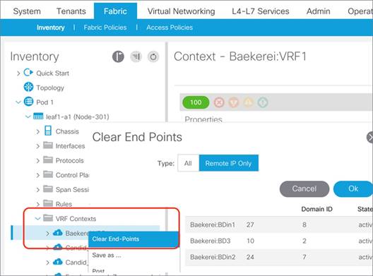
Server Connectivity and NIC Teaming Design Considerations
When connecting servers to Cisco ACI the usual best practice of having multiple NICs for redundancy applies. Typically, this means having two NICs with one connected to one leaf switch and another NIC connected to a different leaf switch.
Commonly used NIC teaming configurations are applicable for Cisco ACI connectivity, with a preference for the configuration of IEEE 802.3ad Link Aggregation (LACP port channels) on the server and vPC with IEEE 802.3ad (LACP) on Cisco ACI. This ensures the use of all links (active/active), that there is redundancy, and that there is verification that the right links are bundled together, thanks to the use of LACP to negotiate the bundling.
While vPC with LACP is the preferred option both with non-virtualized servers and with virtualized servers, due to the variety of NIC teaming options available on server operating systems, you must be aware of other options and how to configure Cisco ACI to interoperate with them.
Sometimes the choice of options other than vPC with LACP is primarily the result of the need for server administrators to configure connectivity without having to ask for network configuration changes. Hence, the use of teaming options that apparently don’t require any network configuration appears as the fastest way to deploy a server. But, these options may not be the best for a server's performance nor for network interoperability, and in fact they may indeed require network configuration changes instead.
This list is a summary of what are the typical considerations for teaming integration with the Cisco ACI fabric:
● Link Aggregation with a port channel (which is essentially "active/active" teaming) with or without the use of the IEEE 802.3ad (LACP) protocol: This type of deployment requires the configuration of a port channel on the Cisco ACI leaf switches, which for redundancy reasons is better if configured as a vPC. In this case, you need the definition of leaf switches that are vPC pairs with the definition of explicit VPC protection groups, and vPC policy groups on Cisco ACI and LACP (if used).
● Active/standby teaming: This option requires a policy group of type Leaf Access Port and is recommended that you also configure port tracking.
● The virtualized server option called "route based on the originating port ID" or "route based on the originating virtual port" or MAC pinning in Cisco terminology and similar options: These options require the configuration of a policy group type Leaf Access Port and with this option we also recommend that you configure port tracking.
● "active/active" non-IEEE 802.3ad teaming configurations, and as a result non-vPC configurations: There are a multitude of options that fall into this category, and they typically give the server the ability to use both NICs upstream and receive traffic only from one NIC. These teaming options are not as optimal as the use of IEEE 802.3ad link aggregation. For these options to work with Cisco ACI, you need to configure a policy group type Leaf Access Port and disable IP address dataplane learning. Refer to the "Endpoint learning considerations / Dataplane learning / When and How to Disable IP Dataplane Learning" section for more information. Enabling port tracking also helps in the case of Cisco ACI leaf switch uplink failure.
Note: For more information about port tracking, refer to the "Designing the Fabric Access / Port Tracking" section.
Design Model for IEEE 802.3ad with a vPC
This section explains the design model for the deployment of server teaming in conjunction with a vPC. This model is equally applicable to non-virtualized servers as well as virtualized servers, because both type of servers implement either static link aggregation (static port channel) or IEEE 802.3ad link aggregation teaming (dynamic port channel with LACP).
Figure 74 illustrates the design for server connectivity using a vPC.
You need to divide the leaf switches by groups of two for the configuration of the Explicit vPC Protection Groups. You need to define one protection group per vPC pair. As an example, leaf 101 and leaf 102 are part of the same explicit vPC protection group.
You should configure as many vPC policy groups as the number of hosts and assign the policy groups to pair of interfaces on two leaf switches. For example, interface 1/1 of leaf 101 and interface 1/1 of leaf 102 must be assigned to the same policy group.
The policy group should have a port channel policy that can be either "Static Channel mode on" or LACP active if using LACP on the servers. Cisco Discovery Protocol or LLDP should be enabled. If using LACP, you need to decide whether to enable the LACP suspend individual option (more on this later).
With a vPC there is no need to enable port tracking, but you may want to enable port tracking anyway for the other ports that may not be configured as vPCs, for instance for ports connected with the equivalent of MAC address pinning.
If you configure an EPG with static binding, you need to enter the physical domain in the domain field, and in the Static Port configuration you need to select the vPCs and the VLANs.
If you use VMM integration, you just need to enter the VMM domain in the domain field of the EPG without having to specify which vPC interfaces should be used. More details about the VMM integration options are given later in the "Server Connectivity (and NIC Teaming) design considerations" section.
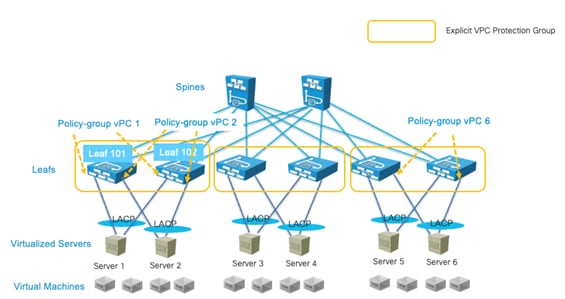
NIC Teaming Configurations for Non-Virtualized Servers
Server Active/Active (802.3ad Dynamic Link Aggregation) Teaming with vPC
You can configure servers NIC interfaces for IEEE 802.3ad link aggregation and the Cisco ACI leaf switch interfaces with a policy group type vPC with an LACP active mode configuration. This provides an active/active type of forwarding where all links are used in both directions. This configuration in Linux bonding is called mode 4, dynamic link aggregation.
With this teaming configuration, the server MAC address appears as coming from a single interface--the vPC interface--even if physically there are 2 or more ports all forwarding traffic for the same MAC address.
Figure 75 illustrates this point. The servers have two NICs: NIC1 and NIC2. NIC1 connects to Leaf101 and NIC2 connects to Leaf102.
Leaf101 and Leaf102 are part of the same explicit VPC protection group. Leaf101 port 1/1 and Leaf102 port 1/1 are part of the same virtual port channel (vPC1). The server answers ARP replies for the IP 30.0.0.101 with the MAC 00:00:00:00:00:01. The traffic from the server with IP address 30.0.0.101 appears with a source MAC address of 00:00:00:00:00:01 from both interfaces. Traffic from the server to the network uses both NICs and traffic from the network to the server uses both NICs also.
For the Cisco ACI configuration, you can follow the recommendations described in the "Design Model for IEEE 802.3ad with vPC" section.
There are server deployments that may require the LACP configuration to be set without the "suspend individual ports" option. This is necessary if the server does PXE boot, as it is not able to negotiate the port channel at the very beginning of the boot up phase. Keeping port channel ports in the individual state when connected to a server during the bootup should not introduce any loops because a server typically won’t switch traffic across the NIC teaming interfaces of the port channel. This applies only if the server (compute) is directly connected to the leaf switch ports. If there is a blade enclosure with a switching component between the server blade and the leaf switches, we recommend that you use LACP suspend individual instead, because blade switches are just like any other external switch in that they could introduce a loop in the topology.
If you configure servers teaming for port channeling, and Cisco ACI leaf switches for vPC, you do not need any special tuning for dataplane learning nor of loop prevention features, such as rogue endpoint control or endpoint loop protection. The vPC interface is logically equivalent to a single interface, so no flapping of MAC or IP addresses occurs.
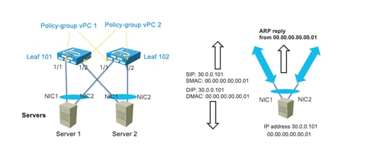
Note When configuring leaf switch pairs with a vPC protection group, the MAC and IP address of servers connected with active/standby teaming or connected with a single interface is synchronized between vPC pairs using the "peer-link" protocol instead of the normal dataplane learning. This requires the FD_VLAN that is assigned to the interface to be present on both devices. With active/standby teaming, this does not require extra configurations because you would have configured the same VLAN for both NICs. In the case of single homed servers, you must make sure that on the peer vPC leaf switch has at least one port assigned to an EPG on the same bridge domain with the same domain and the same VLAN encapsulation as the server interface on the other leaf switch. The next section provides more details.
With active/standby NIC teaming (or active-backup in Linux bonding terminology), one interface is active and one or more is in a standby state. The standby interface is up from a link connectivity perspective, so the VLAN(s) required for forwarding are programmed including the FD_VLAN.
Note Even if the standby interface was down, the VLAN(s) used by the hardware would be programmed because with physical domains the resolution happens when the static port is configured, regardless of the port being up or down. In the case of VMM domains, VMnics are all up and if the resolution is on-demand, it is sufficient that a VM is attached to the vNIC and the ESX host is discovered via LLDP or CDP. At the light of this you can assume that the hardware on the leaf switches where the server is connected is programmed with the necessary VLANs for both interfaces.
The MAC and IP of servers connected via active/standby teaming are learned in the COOP spine-proxy as coming from the leaf VTEP address even in the case where the leaf switches are part of a vPC. A remote vPC pair learns the endpoint information of an active/standby server connected to another vPC pair via regular learning. If the leaf switches are configured as a vPC pair, the endpoint information of active/standby servers is synchronized between the members of a vPC pair via the peer-link protocol and not via regular learning. In this case the FD_VLAN that is used by the active interface on a leaf must also be present on the vPC peer leaf for the endpoint information to be synchronized. In normal circumstances this is not a problem because you would configure the EPG with a static path for each interface with the same encapsulation VLAN.
There are different implementations of the failover process depending on the bonding implementation:
● The MAC address of the active interface stays identical after a failover, so there is no need to remap the IP address of the server to a new MAC address.
● When a failover happens, the newly active interface uses its own MAC address to send traffic. In this case, the IP address-to-MAC address mapping must be updated on all the servers in the same Layer 2 domain. Therefore, with this type of implementation, the server sends a GARP request after a failover.
With the first implementation, the bridge domain configuration does not require any specific configuration if the newly active interface starts sending traffic immediately after the failover. The MAC address-to-VTEP mapping is automatically updated in the endpoint database, and as a result, the IP address-to-VTEP mapping is updated, so everything works correctly.
With the second implementation, the bridge domain must be configured for ARP flooding for the GARP request to reach the servers in the bridge domain. The GARP packet also triggers an update in the endpoint database for the IP address-to-MAC address mapping and IP address-to-VTEP mapping, regardless of whether ARP flooding is enabled.
With active/standby NIC teaming, we recommend that you also enable port tracking.
NIC Teaming Active/Active non-Port Channel-based (non-vPC)
Servers configured with NIC teaming active/active, such as Transmit Load Balancing (TLB) (Linux bonding mode 5), send the same source IP address from multiple NIC cards with different MAC addresses.
As with Active/Standby teaming and leaf switches configured as part of a vPC domain, the MAC address and IP address of servers connected using active/active teaming are learned on the vPC peer through the peer-link protocol and not through regular learning. In this case the FD_VLAN that is used by the interface on a leaf must also be present on the vPC peer leaf for the endpoint information to be synchronized. In normal circumstances this is not a problem because you would configure the EPG with a static path for each interface with the same encapsulation VLAN.
Figure 76 illustrates how TLB teaming works. The server with IP address 30.0.0.101 has two NICs with MAC addresses 00:00:00:00:00:01 and 00:00:00:00:00:02 respectively and it answers ARP requests with only one MAC address, for instance 00:00:00:00:00:01. The server sends traffic from both NICs to the network, and traffic from NIC1 uses a source MAC of 00:00:00:00:00:01 and traffic from NIC2 uses the source MAC address 00:00:00:00:00:02.
The inbound traffic uses only NIC1 because this server answers ARP requests for 30.0.0.101 with the MAC address of NIC1. The traffic flow is asymmetric, in one direction (server-to-client) it uses both NICs in the other direction (client-to-server) instead it uses only one NIC.
To improve this connectivity, we recommend that you change the teaming to IEEE 802.3ad link aggregation/port channeling with LACP in conjunction with vPC on the Cisco ACI leaf switches to use both NICs in both directions.
If the teaming configuration cannot be changed, you can then disable dataplane learning preferably by changing the VRF configuration. Refer to the "Endpoint learning considerations / Dataplane learning / When and How to Disable IP Dataplane Learning" section for more information.
We recommend that you also enable port tracking.
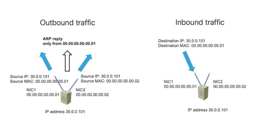
NIC Teaming Configurations for Virtualized Servers (Without the Use of VMM Integration)
Cisco ACI can be integrated with virtualized servers using either EPG static port binding or through a VMM domain:
● With EPG static port configurations (static binding), the VLAN assignment to port groups is static, meaning the assignment is defined by the administrator.
● When you use a VMM domain, the VLAN allocation is dynamic and maintained by the Cisco APIC. The resolution in this case is also dynamic, so the allocation of objects such as a VRF, bridge domain, and EPG on a leaf switch is managed by the Cisco APIC through the discovery of a virtualized host attached to a leaf switch port. This dynamic allocation of resources works if one of the following control plane protocols is in place between the virtualized host and the leaf switch: Cisco Discovery Protocol, LLDP, or OpFlex protocol.
This section assumes the configuration using static binding by manually allocating VLANs to port groups and matching them using static port EPG mapping. In this case, the configuration in Cisco ACI is equivalent to having physical hosts attached to the leaf switch. Therefore, the Cisco ACI fabric configuration is based on the definition of a physical domain in the fabric access configuration as well as in the EPG.
Cisco ACI integrates without problems with most teaming implementations and it is outside of the scope of this document to describe all of them. Hence, this section just highlights VMware teaming options and Microsoft Hyper-V teaming options. Other vendors’ teaming implementation can easily be likened to the ones provided in this section as examples, and the design recommendations can hence be derived by reading these examples.
This section and the next one provide design considerations and recommendations related to integrating virtualized severs with the Cisco ACI fabric with specific focus on teaming options.
For additional information, refer to the following document:
You can find the list of teaming options for VMware hosts by reading knowledge based articles such as the following documents:
https://kb.vmware.com/s/article/1004088
For the purpose of this document, it is enough to highlight the most common teaming options:
● Route based on the originating port ID (or route based on the originating virtual port): With NICs connected to two or more upstream leaf switches. In Cisco ACI terminology, this type of teaming is called also "MAC pinning," but it is neither necessary nor recommended to configure a policy group of type vPC with Port Channel mode for MAC pinning unless you are using VMM integration. You should instead configure the Cisco ACI leaf switch interfaces with a policy group type Leaf Access Port. We recommend that you enable port tracking.
● Route based on an IP address hash: With NICs connected to two upstream leaf switches that are part of the same explicit VPC protection group, this option works with a policy group type vPC with a port channel policy set for Static Channel mode on instead of LACP active. For more information, read the guidelines of the "Design Model for IEEE 802.3ad with vPC".
● LACP teaming on vDS: The configuration of LACP on a VMware vSphere Distributed Switch is described at the following link (https://kb.vmware.com/s/article/2034277). With NICs connected to two upstream leaf switches that are part of the same explicit VPC protection group, with this option you can configure a Cisco ACI policy group type vPC with a port channel policy set for LACP active. For more information, read the guidelines of the "Design Model for IEEE 802.3ad with vPC" section.
● Physical NIC load teaming or load-based teaming: With this configuration, the hypervisor may reassign a virtual machine to a different NIC every 30 seconds depending on the NIC's load. This configuration works with the Cisco ACI policy group type Leaf Access Port, although Cisco ACI offers a port channel policy by the same name for the VMM integration that you don’t need to use. The main concern with this configuration could be having too many moves that may be interpreted by rogue endpoint control or by endpoint loop protection as a problem. The default number of moves and detection interval of these features is respectively 6 moves in an interval of 60 seconds, or 4 moves in an interval of 60 seconds. Therefore, this teaming option should also work fine with the Cisco ACI loop protection features, but testing of the specific server configuration should validate this assumption. We recommend that you enable port tracking.
Another important VMware vDS teaming option is the failback option. With failback enabled, if there’s a reload of a leaf switch, once the leaf switch comes back up, the VMs vNICs are pinned back to where they were prior to the failover. Disabling the failback reduces the traffic drop during a leaf switch reload, but it may result in too many virtual machines sending the traffic using the same leaf switch afterwards instead of being equally distributed across the leaf switches to which they are connected.
This section provides a high level summary of the Hyper-V teaming options to describe which configurations of Cisco ACI work best with them. For an accurate description of all the teaming options of Microsoft servers, refer to the Microsoft documentation at the following link:
https://gallery.technet.microsoft.com/Windows-Server-2012-R2-NIC-85aa1318
Microsoft distinguishes two types of teams:
● The Host Team: This is the team that is used to manage the Hyper-V host.
● The Guest Team: This is the team that is used by the Microsoft Virtual Switch External networks to attach virtual machines.
For the "Host Team" configuration, the same considerations as NIC teaming for non-virtualized hosts apply. This section is meant primarily for giving guidance for the "Guest Team" configuration. Microsoft distinguishes teaming mode and load balancing mode.
You can choose from the following teaming modes:
● Static: This is a static link aggregation configuration. With NICs connected to two upstream leaf switches that are part of the same explicit VPC protection group, this option works with the Cisco ACI policy group type vPC with the port channel policy set to Static mode on. For more information, read the guidelines of the "Design Model for IEEE 802.3ad with vPC" section.
● LACP: With NICs connected to two upstream leaf switches that are part of the same explicit VPC protection group, you can use this option on the virtualized servers and you can configure a Cisco ACI policy group type vPC with a port channel policy set for LACP active. For more information, read the guidelines of the "Design Model for IEEE 802.3ad with vPC" section.
● Switch independent: These are options that theoretically are independent of the switch configuration, but they may instead require some configuration. Switch independent mode teaming can be configured with multiple load balancing modes, and depending on the load balancing mode you may have to disable IP address dataplane learning.
You can choose from the following load balancing modes:
● Hyper-V Port: When using "Hyper-V Port" load balancing, virtual machines are distributed across the network team and each virtual machine’s outbound and inbound traffic is handled by a specific active NIC. With NICs connected to two or more upstream leaf switches, this option works with a policy group type Leaf Access Port without any special additional configuration. In Cisco ACI terminology this type of teaming is called also "MAC pinning", but it is neither necessary nor recommended to configure a policy group of type vPC with Port Channel mode for MAC pinning (unless you are using VMM integration). We recommend that you enable port tracking.
● Address Hash: load balances outbound network traffic across all active NICs, but only receives inbound traffic using one of the NICs in the team. With NICs connected to two or more upstream leaf switches, this this option works with a policy group type Leaf Access Port. With this option you need to disable IP address dataplane learning as described in the section "Endpoint learning considerations / Dataplane learning / When and How to Disable IP Dataplane Learning" section. We recommend that you enable port tracking.
● Dynamic: Outbound traffic is distributed based on a hash of the TCP Ports and IP addresses. Dynamic mode also rebalances traffic in real time so that a given outbound flow may move back and forth between team members. Inbound traffic is using one NIC in the team. With NICs connected to two or more upstream leaf switches, this option works with a policy group type Leaf Access Port. With this option you need to disable IP address dataplane learning as described in the "Endpoint learning considerations / Dataplane learning / When and How to Disable IP Dataplane Learning" section. We recommend that you enable port tracking.
Table 12 Microsoft Server Teaming Configuration Options and corresponding Cisco ACI configuration
| Description |
Cisco ACI Fabric configuration |
|
| Teaming Mode: Static |
It is a static port channel |
Configure a policy group type vPC with Port Channel policy of type Static mode on. |
| Teaming Mode: LACP |
It is an IEEE 802.3ad port channel |
Configure a policy group type vPC with Port Channel policy of type LACP active. |
| Teaming Mode: Switch independent Load Balancing: Address Hash or Dynamic |
It is a type of active/active load balancing teaming |
Fabric Access configured with a policy group type Leaf Access Port. You need to disable IP dataplane learning. Port tracking enabled. |
| Teaming Mode: Switch independent Load Balancing: Hyper-V port |
It is similar to MAC pinning in Cisco terminology |
Fabric Access configured with a policy group type Leaf Access Port. Port tracking enabled. |
NIC Teaming Configurations for Virtualized Servers with VMM Integration
Besides using EPGs with static port (static binding) matching, Cisco ACI can be integrated with virtualized servers with an API integration called Virtual Machine Manager (VMM) integration.
As an example, by integrating the Cisco APIC and VMware vCenter with the VMM integration, Cisco APIC configures a vDS. It creates port groups that match the EPGs where the VMM domain is configured, it coordinates the VLAN configuration on vDS port groups to encapsulate traffic with VLANs, and it programs also the teaming configuration on the vDS port groups. In fact, when using VMM integration, the admin cannot configure NIC teaming directly on the ESXi hosts, Cisco APIC programs the NIC teaming on the dynamically created vDS port group.
With VMM integration, and more specifically in this example with VMM integration with VMware vSphere, Cisco APIC manages the following networking properties on VMware vSphere:
● On VMware vDS: LLDP, CDP, MTU, LACP, ERSPAN, statistics
● On the VMware vDS port groups: VLAN assignment and teaming and failover on the port groups
In addition to this, and depending on the Resolution immediacy configuration, Cisco ACI also programs VLANs, bridge domains, and VRF instances only on the leaf switches where they are needed. If you configure the EPG with a VMM domain and you choose Resolution to be on-demand, Cisco ACI uses the API integration with the Virtual Machine Manager to figure out on which leaf switch to program the VLAN used by this EPG, port group, bridge domain, and VRF. This is described in the "Resolution and Deployment Immediacy" section.
This section and the following sections discuss the teaming configurations related to the deployment of Cisco ACI with a virtualized environment and, in particular, with VMware vSphere with VMM integration.
For additional information, refer to the following document:
CDP and LLDP in the Policy Group Configuration
Special considerations must be given to the LLDP and CDP configuration, as these protocols are key to resolving the policies on the leaf switches. The following key considerations apply:
● VMware vDS can run only CDP or LLDP, not both at the same time.
● LLDP takes precedence if both LLDP and CDP are defined.
● To enable CDP, the policy group for the interface should be configured with LLDP disabled and CDP enabled.
● By default, LLDP is enabled and CDP is disabled.
Make sure that you include the Cisco Discovery Protocol or LLDP configuration in the policy group that you assign to the interfaces connected to the VMware ESXi hosts.
Configuring Teaming using the Cisco ACI VMM Integration
If you deploy a VMware vDS controlled by a Cisco APIC, you should not configure NIC teaming directly on the VMware vDS.
Cisco ACI lets you configure the teaming options on the vDS port groups using a construct called the port channel policy (Fabric > Access Policies > Policies > Interface > Port Channel), which you need to add to the VMM VSwitch Policy (more on this later). The teaming options are described in the next section.
Cisco ACI offers two mechanisms to set the teaming configuration on the virtualized hosts connected to the Cisco ACI leaf switches:
● Match the Cisco ACI policy group leaf switch configuration and deriving the compatible NIC teaming configuration. This is based on the configuration of the AAEP. For instance, If you configure Cisco ACI leaf switches with policy group type leaf access port, Cisco ACI automatically programs the vDS port group with "route based on the originating virtual port." If you instead configure a policy group type vPC with a port channel policy of type MAC pinning, Cisco ACI programs the vDS port group with the same teaming option "route based on the originating virtual port." If you configure a policy group of type vPC with a Port Channel Policy Static Channel – Mode On, Cisco ACI will program IP hash teaming on the VMware vDS port groups accordingly.
● Explicitly choose the NIC teaming configuration for the vDS port groups independently of the policy group configuration. This is based on the configuration of the VMM VSwitch port channel policy. You can configure the "vswitch policy" port channel policy (Virtual Networking > VMware > vCenter Domain Name that you created > Policy > VSwitch Policy > Port Channel Policy) for any of the teaming options, and this overrides the previous logic by pushing a specific teaming configuration to the vDS port groups regardless of the policy group configuration on the interfaces (that is, regardless of the AAEP configuration).
Figure 77 illustrates the first deployment option: the policy group configuration is automatically pushed by Cisco APIC to the vDS port group teaming and failover configuration.
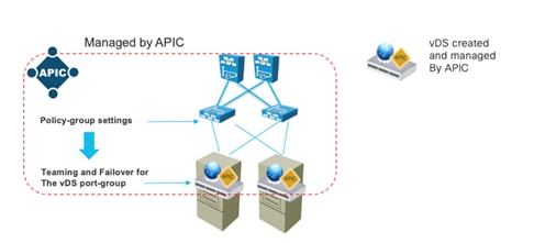
This automatic configuration of teaming based on the policy groups (AAEP) requires a consistent policy group configuration on all the Cisco ACI leaf switch ports attached to the ESXi hosts that are part of the same VMM vDS.
Because a vDS port group spans all of the virtualized hosts in the same vDS, there must be a teaming configuration that works across all of the hosts VMNICs. If some Cisco ACI ports are configured as a static port channel and other ports are configured as LACP active, it is not clear which NIC teaming configuration must be assigned to a vDS port group that encompasses these ports.
Cisco ACI implements this logic by using the AAEP that includes the VMM domain configuration:
● If the AAEP that includes the VMM domain is used only by policy groups type leaf access port, Cisco ACI programs the vDS port groups with the NIC Teaming option "Route based on the originating virtual port."
● If the AAEP that includes the VMM domain is used only by policy groups type vPC interface, Cisco ACI programs the vDS port groups with the NIC Teaming option corresponding to the port channel policy defined in the policy groups that must be consistent.
If because of testing or other reasons, you have other policy groups that are not assigned to any ports because there is no interface profile using them, and these policy groups are associated with the same AAEP, they may influence the NIC teaming configuration. For instance, you may have an unused vPC policy group with port channel policy Static Channel – mode ON associated with the AAEP that otherwise is used by policy groups of type leaf access port, and this will cause the NIC teaming configuration to be set to IP hash instead of route based on the originating virtual port.
To avoid this type of misconfiguration, you can configure the "vswitch policy" port channel policy (Virtual Networking > VMware > vCenter Domain Name that you created > Policy > VSwitch Policy > Port Channel Policy), which overrides the previous logic.
Teaming Options with VMM Integration
You can configure Cisco ACI leaf switches and vDS port group teaming with the following options:
● Static Channel - Mode On or IP hash in VMware terminology: This option combined with the configuration of vPC on the ACI leaf switches offers full use of the bandwidth in both directions of the traffic.
● LACP: IP hash teaming combined with LACP in the vDS uplink port group (Manage > Settings > Policies > LACP). This option combined with the configuration of vPC on the ACI leaf switches offers full use of the bandwidth in both directions of the traffic and the use of LACP offers the best integration with Cisco ACI leaf switches for both forwarding and failover.
● Enhanced LACP: From a Cisco ACI leaf switch port perspective, this option is the same as LACP, but from a virtualized host perspective, enhanced LACP offers more flexibility about how to aggregate the VMNICs in port channels and which load balancing (hashing) option to use to forward traffic. The enhanced LACP option requires the configuration of the policy group type vPC port channel policy, but also the configuration of a VMM VSwitch port channel policy. For more information, see the "Design Model for IEEE 802.3ad with a vPC" section.
● MAC pinning or route based on the originating virtual port in VMware terminology: With this option, each virtual machine uses one of the NICs (VNMICs) and uses the other NICs (VMNICs) as backup. This is the default teaming when using policy groups type access leaf switch port, but this option can also be set as a port channel policy in a policy group of type vPC. For more information, see the "Choosing between Policy-Group type Access Leaf Port and vPC" section.
● MAC Pinning-Physical-NIC-load mode or Route based on NIC Load in VMware terminology: this option is similar to the MAC pinning option, but it sets the NIC teaming on the virtualized host for the option that takes into account the load of the physical NIC to achieve better vNIC-to-VMNIC load distribution. If the Cisco ACI leaf switch ports are configured as a policy group type access, this option must be configured as a VMM vSwitch port channel policy to override the AAEP configuration. If the Cisco ACI leaf switch ports are configured as a policy group type vPC, this option is one of the port channel policy options.
● Explicit Failover Order: this option was introduced in Cisco ACI 4.2(1) to allow the definition of a specific failover order of NICs on a per EPG basis. If the Cisco ACI leaf switch ports are configured as a policy group type access, this option must be configured as a VMM vSwitch port channel policy to override the AAEP configuration. If the Cisco ACI leaf switch ports are configured as a policy group type vPC, this option is one of the port channel policy options. When you define an EPG and associate it with a VMM domain, you can specify a list of NICs by their numerical value. For example, if you enter "1" in the "active uplinks order" field, Cisco ACI programs uplink1 as Active Uplink in the vDS teaming and failover configuration.
With the first three options (Static Channel, LACP, Enhanced LACP), you need to configure as many vPC policy groups (Fabric > Access Policies > Interfaces > Leaf Interfaces > Policy Groups > VPC Interface) as the number of ESXi hosts and assign them to pairs of interfaces on two leaf switches. The leaf switches must be vPC peers, or in other words leaf switches that are part of the same explicit VPC protection group. The Design Model for IEEE 802.3ad with VPC section describes how to design the fabric for host connectivity using vPC and the same guidelines apply when using VMM domain integration.
For the remaining teaming options (MAC pinning, MAC Pinning-Physical-NIC-load mode, Explicit Failover Order), you can configure Cisco ACI ports either with a policy group type access or with a policy group type vPC as described in more detail in the next section.
Choosing between Policy-Group type Access Leaf Port and vPC
If you intend to implement a design that is based on teaming options that do not use static port channeling nor LACP, you can configure Cisco ACI ports as policy group type leaf access ports (Fabric > Access Policies > Interfaces > Leaf Interfaces > Policy Groups > Leaf Access Port) or as a policy group type vPC.
If you use a policy group type leaf access port, you can configure identically all the Cisco ACI leaf switch ports that connect to the virtualized hosts, or to be more accurate, to the NICs of the virtualized hosts that are used by the same vDS. This means that the ports will all have the same policy group type leaf access. You should also configure Virtual Networking > VMware >….> VSwitch Policy > Port Channel Policy with the port channel policy that matches your teaming choice: MAC pinning, MAC Pinning-Physical-NIC-load mode, or Explicit Failover. This may not be necessary for the designs using MAC pinning, but it prevents misconfigurations.
If you use a policy group type vPC, the usual vPC configurations apply, which means that you have to create as many policy groups as ESXi hosts. The main advantage of this configuration is that Cisco ACI configures both the Cisco ACI leaf switch ports and the virtualized server teaming.
If you use a policy group type vPC with MAC pinning, the resulting configuration is a combination of a port channel and MAC pinning. This configuration programs the Cisco ACI leaf switch ports for LACP and the vDS port group with "route based on the originating virtual port." The Cisco ACI leaf switch ports stay in the Individual state; hence they operate just like normal ports. There is no specific reason for having LACP and MAC pinning simultaneously, except some very specific designs that are outside of the scope of this document.
The following table summarizes the pros and cons of using a policy group type access configuration versus a policy group type vPC.
Table 13 Teaming Options with a Policy Group Type Access and a Policy Group Type vPC
| Using Policy Group Type Access |
Using Policy Group Type vPC |
|
| Number of policy group configurations required |
One policy group for all the leaf switch ports connected to the virtualized servers |
One policy group per virtualized host |
| Teaming Mode: Static Channel – Mode On |
N/A |
Yes |
| Teaming Mode: LACP |
N/A |
Yes |
| Teaming Mode: MAC pinning |
Yes |
Yes (LACP runs even if not necessary)
|
| Teaming Mode: Physical NIC Load |
Yes with additional configuration of the VMM VSwitch Port Channel Policy |
Yes |
| Teaming Mode: Explicit Failover Order |
Yes with additional configuration of the VMM VSwitch Port Channel Policy |
Yes |
Using LACP Between the Virtualized Host and the Cisco ACI Leaf switches
Using IEEE 802.3ad link aggregation (LACP port channels) on virtualized servers and vPC with IEEE 802.3ad (LACP) on Cisco ACI ensures the use of all links (active/active). IEEE 802.3ad link aggregation provides redundancy as well as the verification that the right links are bundled together, thanks to the use of LACP to negotiate the bundling.
For virtualized servers dual connected to Cisco ACI leaf switches, you can configure a port channel by simply using a policy group type vPC with port channel policy Static Channel - Mode On. This option sets the Cisco ACI leaf switch ports for static port channeling and the NIC teaming on the virtualized host for load balancing with "IP hash."
If you want the port channel negotiation to be based on the Link Aggregation Control Protocol, the configuration varies primarily depending on which version of LACP is configured on VMware vSphere: regular LACP or enhanced LACP.
LACP is configurable in the vDS in VMware vSphere 5.1, 5.5, 6.0, and 6.5, and later releases. The original LACP implementation on VMware vSphere assumes that all VMNICs are part of the same port channel (or Link Aggregation Group). Enhanced LACP was introduced in VMware vSphere 5.5 and it offers more flexibility about how to aggregate the VMNICs in port channels and which load balancing (hashing) option to use to forward traffic.
You can find more information about LACP and enhanced LACP in the following documents:
● https://kb.vmware.com/s/article/2051826
Once you have enabled enhanced LACP on VMware vSphere, you need to configure LACP always using enhanced LACP. You cannot change the configuration back to regular LACP.
Cisco ACI offers support for the enhanced LACP configuration starting from Cisco ACI 4.0. Hence, you can configure Cisco ACI for either the original VMware vSphere LACP implementation or for enhanced LACP as follows:
● Regular LACP: For this configuration, you just need to configure a policy group type vPC with port channel policy LACP Active. This option sets the Cisco ACI leaf switch ports for port channeling with LACP and the NIC teaming on the virtualized host for load balancing with "IP hash." If VMware vSphere is not using enhanced LACP, the option also enables LACP on the vDS uplink port group (in vSphere vDS uplink port group Manage > Settings > Policies > LACP). You should configure LACP Active: one device must be LACP active for the port channel to go up. If the expectation is that the server boots using PXE boot, you should deselect the "Suspend Individual Port" option.
● Enhanced LACP: For this configuration, you need to configure a policy group type vPC with port channel policy LACP Active on the Cisco ACI leaf switch ports. Different from the use of regular LACP, this configuration doesn’t automatically enable LACP on the vDS. To do this, you need to configure the VMM vSwitch (VM Networking > VMM Domain > vSwitch policies) to define a LAG group. The LAG group appears on the vDS and the virtualization administrator must assign VMNICs (uplinks) to the LAG. From this moment on, whenever you configure an EPG and you associate the VMM domain, you can choose the LAG group that the EPG is going to use. As of Cisco ACI 5.1 enhanced LACP is not compatible with the use of a service graph with virtual appliances. Hence, if you have Layer 4 to Layer 7 service devices as virtual appliances, you should not use enhanced LACP. There is a plan to remove this restriction in a future release.
Figure 78 illustrates the configuration of the LAG from the vswitch policy (VM Networking > VMM Domain > vSwitch policies) in the VMM domain. In the vSwitch, policy you can define multiple enhanced LAG policies, and you can choose among multiple load balancing algorithms and the number of uplinks.
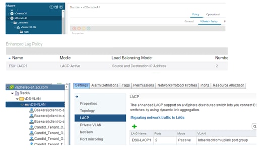
At the bottom right of Figure 79, you can see the resulting configuration on the vDS managed by Cisco APIC: that is the definition of a Link Aggregation Group (LAG).
The virtualization administrator must then assign VMNICs (uplinks) to the LAG groups created by Cisco ACI (Figure 79) by going to VMware vSphere and selecting the Host > Configure > Networking > Virtual Switches > Manage Physical Adapters.
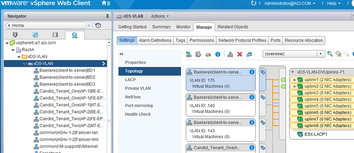
When associating the EPG with the VMM domain (Figure 80), you can choose the LAG policy that you want the EPG to use. This defines which set of ESXi host uplinks are going to be used by the EPG and which port channel hashing algorithm is used.
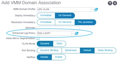
You can find more information about the Cisco ACI integration with the enhanced LACP feature at the following document:
Teaming Configuration with Servers Not Directly Attached to the Cisco ACI Leaf switches
When using VMM integration, you should not configure teaming on the vDS port groups directly. This is also true when the servers are not directly attached to the Cisco ACI leaf switches.
The teaming configuration on the vDS port groups is controlled by the following Cisco ACI configurations:
● Fabric Access > Interface Policies > Policy Group
● VM Networking > VMM Domain > vSwitch policies
The VMware vSwitch policy configuration overrides the policy group configuration. This can be useful if the virtualized hosts are not directly connected to Cisco ACI leaf switches, but to a Layer 2 network (or a UCS Fabric Interconnect) that is between the servers and the Cisco ACI leaf switches.
Figure 81 presents an example of servers connected to Cisco ACI through an intermediate network:
● The network between the servers and the Cisco ACI leaf switches should be configured to trunk all the VLANs that are defined in the VMM domain.
● The policy group configuration on the Cisco ACI leaf switches should be defined to match the external switches configurations that attach to the Cisco ACI leaf switches.
● The VMM VMware vSwitch policy configuration should be defined to configure the teaming on the vDS port groups that connect to the external Layer 2 network.
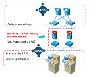
UCS connectivity with Fabric Interconnect
The most commonly used UCS fabric interconnect connectivity to Cisco ACI leaf switches is with UCS fabric interconnects’ uplinks connected to a pair of Cisco ACI leaf switches using vPC. This design provides link and node-level redundancy, higher aggregate bandwidth, and the flexibility to increase the bandwidth as the uplink bandwidth needs grow.
In this design, the Cisco ACI interface policy group configuration for the leaf switch interfaces connected to the UCS fabric interconnects’ uplinks must have proper vPC configuration.
MAC pinning or equivalent redundant NIC teaming designs that don’t use a port channel are a valid design option for the server side teaming configuration because UCS fabric interconnects’ downlinks connected to the UCS blades, or UCS rack mount servers don’t support vPCs or port channels.
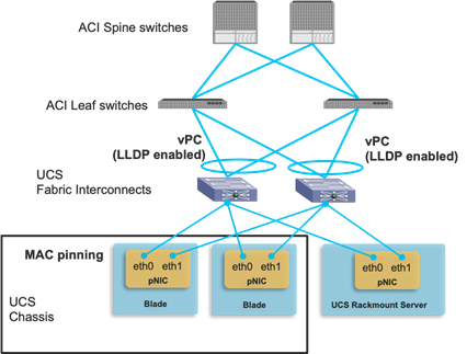
When choosing which VLANs to use for Cisco ACI infra VLAN, EPGs and port groups on the UCS blades, remember that Cisco UCS reserves the following VLANs:
● FI-6200/FI-6332/FI-6332-16UP/FI-6324: 4030-4047. Note: VLAN 4048 is being used by vsan 1.
● FI-6454: 4030-4047 (fixed), 3915-4042 (can be moved to a different 128 contiguous block VLAN, but requires a reboot). See the following document for more information:
When integrating UCS virtualized servers with VMware VMM domain integration, there are additional design/configuration considerations related to Cisco ACI policy resolution. If you are configuring Cisco ACI for on-demand resolution or deployment immediacy, this requires neighbor discovery by using LLDP or CDP, unless resolution immediacy is instead set to pre-provision, in which case there is no need for neighbor discovery, and the following considerations apply:
● LLDP is always enabled on the UCS fabric interconnects uplinks. Thus, the use of LLDP in the Cisco ACI interface policy group is the only valid option for neighbor discovery between Cisco ACI leaf switches and UCS fabric interconnects’ uplinks.
● Enabling CDP or LLDP on the UCS network control policy for the UCS fabric interconnect downlink (vEthernet interface) is required.
● Enabling CDP of LLDP on the VMware vSwitch policy at the VMM domain is required and it must use the same discovery protocol (CDP or LLDP) that the UCS fabric interconnect downlinks use. The configuration location on Cisco APIC is at Virtual Networking > VMware > VMM_domain_name > Policy > VSwitch Policy.
● Be careful when changing the management IP address of the fabric interconnect. This may cause flapping in the LLDP information, which could cause traffic disruption while Cisco ACI policies are being resolved.
With VMM integration, Cisco ACI assigns VLANs dynamically to vDS port groups. Therefore, it is required that VLANs must be configured on the UCS fabric interconnects because Cisco APIC doesn’t take care of external router or switch configurations outside of the Cisco ACI fabric in general. For the sake of simplicity, admins typically configure the entire range of dynamic VLANs on the fabric interconnect to avoid having to manually add VLANs every time a new EPG and associated port group are created. This operation can be simplified by using the ExternalSwitch app.
The figure below illustrates the difference between integrating UCS fabric interconnects with Cisco ACI without the app and with the app.
If you are not using the ExternalSwitch app, the VLANs provisioning on the Cisco ACI fabric and external switch (UCS fabric interconnect in this example) is done separately and by hand. Even if dynamic VLAN provisioning with VMM domain is enabled on the Cisco ACI fabric, the UCS VLAN configuration is static. You must allow all of the VLANs in the VLAN pool on the UCS fabric interconnects even before the EPGs are deployed to the Cisco ACI leaf switches, which consumes unnecessary resources on the fabric interconnects.
By using the ExternalSwitch app, once VLANs are provisioned on the Cisco ACI fabric, the VLANs on fabric interconnects are configured automatically, which simplifies the end-to-end network provisioning from the Cisco ACI fabric to servers and virtual machines.
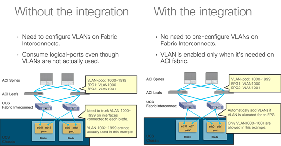
The ExternalSwitch app is available at Cisco DC App Center: https://dcappcenter.cisco.com/.
Designing External Layer 3 Connectivity
This section explains how Cisco ACI can connect to outside networks using Layer 3 routing. It explains the route exchange between Cisco ACI and the external routers, and how to use dynamic routing protocols between the Cisco ACI border leaf switch and external routers. It also explores the forwarding behavior between internal and external endpoints and the way that policy is enforced for the traffic flow between them. Cisco ACI refers to external Layer 3 connectivity as an L3Out connection.
In most Cisco ACI configurations, route peering and static routing are performed on a per-VRF basis on leaf switches, in a manner similar to the use of VRF-lite on traditional routing platforms. Leaf switches on which L3Outs are deployed are called border leaf switches. External prefixes that are learned on a per-VRF basis on a border leaf switch are redistributed into MP-BGP and, as a result, installed on the other leaf switches.
The evolution of L3Out: VRF-lite, GOLF and SR/MPLS handoff
L3Outs have evolved since the initial release of Cisco ACI. The original L3Out implementation had multiple limitations:
● Contract (policy TCAM) scalability on border leaf switches with first generation hardware: In the original L3Out architecture, all the contract rules between a L3Out and regular EPGs were deployed border leaf switches. This made the border leaf switch a bottleneck due to the limited policy TCAM capacity on first generation leaf switches.
● Route scalability: The maximum number of Longest Prefix Match (LPM) routes was 10K (IPv4) on first generation leaf switches. If this was not enough for large data centers, the administrator would deploy L3Outs on multiple sets of border leaf switches.
● Potential asymmetric traffic flow in Cisco ACI Multi-Pod design: In a Cisco ACI Multi-Pod setup, both pods are typically connected to the outside using their own L3Out in each pod. In such a scenario, traffic from the outside may come to pod 2 even though the destination server resides in pod 1. This is because Cisco ACI fabric advertises the bridge domain subnet of the server from both pods in case the bridge domain is deployed on both pods. As a result, the external router on the outside has an ECMP route for the bridge domain subnet. This may cause inefficient traffic flow across pods. For instance, traffic may be going through pod2, IPN, pod1 to the destination endpoint in pod 1 instead of directly going to pod 1.
To address the first concern regarding the policy TCAM, Policy Control Enforcement Direction "Ingress" was introduced on Cisco APIC release 1.2(1). This enables to deploy contract rules in a distributed manner on leaf switches where servers are connected instead of deploying all L3Out related contracts on a border leaf switch. Newer Cisco ACI leaf switch models have been introduced since with bigger policy TCAMs and contracts filter compression features.
For the other two concerns, a solution called GOLF (Giant OverLay Forwarding) was introduced in Cisco APIC release 2.0(1). This is essentially an L3Out on spine switches. This provided higher route scalability and traffic symmetry through the spine switches and IPN (Inter-Pod Network) to the outside. GOLF uses VXLAN BGP-EVPN between spine switches and external routers. However, GOLF has some drawbacks such as no multicast routing support, no route leaking across VRF instances within the Cisco ACI fabric. Also, GOLF relies on OpFlex to provide VNID information for Cisco ACI VRF instances between spine switches and external routers. While this is a brilliant solution on the one hand, it limits the choice of external routers on the other hand.
Later on, various features were introduced to address the said concerns using regular L3Outs on a border leaf switch without GOLF:
● For the route scalability, the forwarding scale profiles feature was introduced with high LPM profile in Cisco APIC release 3.2(1). This enables a border leaf switch with Cisco cloud ASIC (that is, a second generation or later switch) to support a large number of LPM routes, larger than what GOLF can support on spine switches.
● For the inefficient asymmetric traffic flow across pods, the host route advertisement feature (also known as host-based routing) for L3Outs was introduced in Cisco APIC release 4.0(1). This feature enables each pod to advertise each endpoint that resides in its respective pod as /32 host routes on top of the bridge domain subnet. With the host route from the pod that actually owns the endpoint, the external router can send traffic to the appropriate pod directly without potentially going through another pod due to ECMP.
● MPLS support was introduced in Cisco APIC release 5.0(1) for L3Outs on a border leaf switch to further extend the outside connectivity option through leaf switches. With MPLS, the outside connectivity on a border leaf switch can exchange the information about multiple VRF instances using one BGP-EVPN session instead of having to establish BGP sessions per VRF. This used to be the advantage available only using GOLF, but now an MPLS L3Out provides the same advantage.
With these evolutions, GOLF appears just as an interim evolution of the L3Out and currently we recommend that you use L3Outs on a leaf switch for any new deployment.
Layer 3 Outside (L3Out) and External Routed Networks
In a Cisco ACI fabric, the bridge domain is not meant for the connectivity of routing devices, and this is why you cannot configure static or dynamic routes directly on a bridge domain. You instead need to use a specific construct for routing configurations: the L3Out.
This section describes the building blocks and the main configuration options of the L3Out. For more details, you can refer to the Cisco APIC Layer 3 Networking Configuration Guide or the white paper L3Out Guide:
● Cisco APIC Layer 3 Networking Configuration Guide (for Cisco ACI release 5.1):
https://www.cisco.com/c/en/us/td/docs/dcn/aci/apic/5x/l3-configuration/cisco-apic-layer-3-networking-configuration-guide-51x.html
● Cisco APIC Layer 3 Networking Configuration Guide (for other Cisco ACI releases):
https://www.cisco.com/c/en/us/support/cloud-systems-management/application-policy-infrastructure-controller-apic/tsd-products-support-series-home.html
(Configuration Guides > General Information)
● L3Out Guide white paper:
https://www.cisco.com/c/en/us/solutions/collateral/data-center-virtualization/application-centric-infrastructure/guide-c07-743150.html
An L3Out policy is used to configure interfaces, protocols, and protocol parameters necessary to provide IP address connectivity to external routing devices. An L3Out connection is always associated with a VRF. L3Out connections are configured using the External Routed Networks option on the Networking menu for a tenant.
Part of the L3Out configuration involves also defining an external network (also known as an external EPG) for the purpose of access-list filtering. The external network is used to define which subnets are potentially accessible through the Layer 3 routed connection. In Figure 84, the networks 50.1.0.0/16 and 50.2.0.0/16 are accessible outside the fabric through an L3Out connection. As part of the L3Out configuration, these subnets should be defined as external networks. Alternatively, an external network could be defined as 0.0.0.0/0 to cover all possible destinations, but in case of multiple L3Outs, you should use more specific subnets in the external network definition. Refer to the "External network (external EPG) configuration options" section for more information.
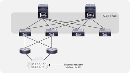
After an external network has been defined, contracts are required between internal EPGs and the external networks for traffic to flow. When defining an external network, check the box External Subnets for the External EPG, as shown in Figure 85. The other checkboxes are relevant for transit and shared-services scenarios and are described later in this section.
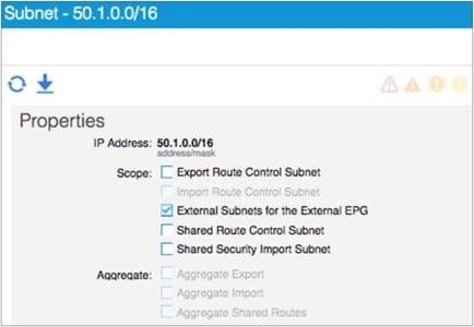
L3Out policies, or external routed networks, provide IP address connectivity between a VRF and an external IP address network. Each L3Out connection is associated with one VRF instance only. A VRF may not have an L3Out connection if IP address connectivity to the outside is not required.
Figure 86 shows the object model for an L3Out. This helps in understanding the main building blocks of the L3Out model.
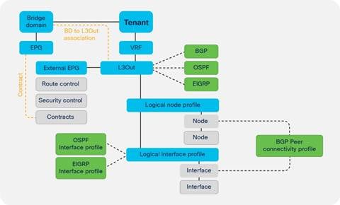
The L3Out policy is associated with a VRF and consists of the following:
● Logical node profile: This is the leaf switch-wide VRF routing configuration, whether it is dynamic or static routing. For example, if you have two border leaf switches, the logical node profile consists of two leaf switches.
● Logical interface profile: This is the configuration of Layer 3 interfaces or SVIs on the leaf switch defined by the logical node profile. The interface selected by the logical interface profile must have been configured with a routed domain in the fabric access policy. This routed domain may also include VLANs if the logical interface profile defines SVIs.
● External network and EPG: This is the configuration object that classifies traffic from the outside into a security zone.
The L3Out connection must be referenced by the bridge domain whose subnets need to be advertised to the outside.
An L3Out configuration always includes a router ID for each leaf switch as part of the node profile configuration, regardless of whether the L3Out connection is configured for dynamic routing or static routing.
L3Out Router ID Considerations
When configuring a logical node profile under an L3Out configuration, you have to specify a router ID. An option exists to create a loopback address with the same IP address as that configured for the router ID.
We recommend that you apply the following best practices for L3Out router IDs:
● Each leaf switch should use a unique router ID per VRF. When configuring an L3Out on multiple border leaf switches, each switch (node profile) should have a unique router ID.
● Use the same router ID value for all L3Out connections on the same node within the same VRF. Cisco ACI raises a fault if different router IDs are configured for L3Out connections on the same node for the same VRF.
● A router ID for a L3Out with static routing must be specified even if no dynamic routing is used for the L3Out connection. The Use Router ID as Loopback Address option should be unchecked, and the same rules as outlined previously apply regarding the router ID value.
● There is no need to create a loopback interface with a router ID for OSPF, EIGRP, and static L3Out connections. This option is needed only for:
o BGP when establishing BGP peering sessions from a loopback address.
o L3Out for multicast routing and PIM.
● Create a loopback interface for BGP multihop peering between loopback addresses. You can establish BGP peers sessions to a loopback address that is not the router ID. To achieve this, disable the Use Router ID as Loopback Address option and specify a loopback address that is different from the router ID.
Make sure that router IDs are unique within a routing domain. In other words, the router ID should be unique for each node within a VRF. The same router ID can be used on the same node within different VRF instances. However, if the VRF instances are joined to the same routing domain by an external device, then the same router ID should not be used in the different VRF instances.
Route Announcement Options for the Layer 3 Outside (L3Out)
This section describes the configurations needed to specify which bridge domain subnets are announced to the outside routed network and which outside routes are imported into the Cisco ACI fabric.
Through the evolution of the L3Out, various methods were introduced for an L3Out to advertise Cisco ACI bridge domain subnets and external routes learned from another L3Out (known as transit routing). The traditional way to advertise the bridge domain subnet from the L3Out is to enter information in the bridge domain about with which L3Out it is associated and to define external EPG subnets for both route advertisement and contracts. Cisco APIC then interprets the intentions of those policies and creates an internal route map to control route advertisement on the border leaf switches. However, this configuration may get confusing due to the number of subnets to advertise and due to the complexity with many scopes under the subnets in external EPGs.
This section describes the currently recommended configuration that allows users to manage route advertisements only with route maps, called the route control profile or route profile in Cisco ACI, and use external EPGs purely for contracts or shared service just as with internal EPGs. For other types of configurations refer to the ACI BD subnet advertisement section in the L3Out Guide.
There are many types of route maps (route profile) in Cisco ACI. However, this section focuses on two default route maps called default-export and default-import, which are the recommended configuration. You can forget about other non-default route maps. Under each L3Out, you can create one default-export and default-import route map.
● default-export: This manages which routes to advertise.
● default-import: This manages which routes to accept from external routers.
These default route maps (default-export and default-import) can be configured under "Tenant > Networking > L3Outs > Route map for import and export route control," or "Tenant > Networking > External Routed Networks > Route Maps/Profiles" in older Cisco APIC releases.
In each default route map, you can define route map sequences with various match and set rules along with action permit and deny just as with a normal router. An IP address prefix-list is the most common match rule to be used. By default, default-import does not take effect unless the Route Control Enforcement option "Import" is selected under each L3Out. The option is located at "Tenant > Networking > L3Outs > your_L3Out," or "Tenant > Networking > External Routed Networks > your_L3Out" in older Cisco APIC releases.
If you follow the recommendation to use default route maps for all route controls and external EPGs only for contracts and shared service, you must use route maps of type "Matching Routing Policy Only" for default-export and default-import. This is because if you do otherwise, Cisco APIC will try to combine information from external EPGs and route maps to decide the content of the final route maps to be deployed.
Under the external EPGs configuration and the bridge domains configuration, you may have noticed the option to configure the route profile association. You should use these options only if you are not using default route maps. With default route maps, there is no need to configure such an association. You can leave all of them untouched when using default route maps.
Default-export will advertise both bridge domain subnets and external routes that match the configured IP address prefix-list. However, to announce bridge domain subnets, two configurations are still required:
● You must select the "Advertised Externally" scope under the bridge domain subnet.
● You must configure contracts between an EPG under the bridge domain and an external EPG under the L3Out.
Contracts are required for the bridge domain subnets to be available on border leaf switches so that L3Out routing protocols can advertise with the configured route map.
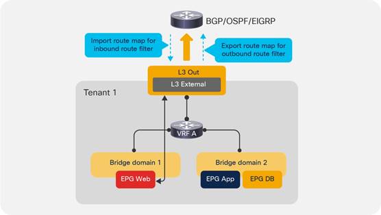
Route Map Handling Differences Between OSPF, EIGRP and BGP
In the case of OSPF and EIGRP, be aware that all L3Outs on the same border leaf switch in the same VRF internally share the same route map for the route control for all of their neighbors regardless of the configuration option, such as default route maps or bridge domain association to the L3Out. This means that the route control configured in L3Out A will also affect L3Out B when OSPF, EIGRP, or both are used on the same border leaf switch in the same VRF.
In the case of BGP, each L3Out owns its own internal route map and you can have more granular route controls even within the same border leaf switch. However, the same route control is applied to all BGP peers in the same L3Out. In terms of this behavior, there are no differences between default route maps and other route control options, such as non-default route maps or bridge domain association to the L3Out.
If you need more granularity in BGP, the per-peer BGP route map feature was introduced in Cisco APIC release 4.2(1). Only when you need this per-peer BGP route map, you need to use non-default route maps. In that case, such route maps need to be created under "Tenant > Policies > Protocols > Route Maps for Route Control" and the name of the route maps cannot be "default-export" or "default-import."
External Network (External EPG) Configuration Options
The external endpoints are assigned to an external EPG, which the GUI calls an external network. For the L3Out connections, the external endpoints can be mapped to an external EPG based on IP address prefixes or host addresses.
Note: EPGs for external or outside endpoints are sometimes referred to as prefix-based EPGs if defined as networks and masks, or IP-based EPGs if defined as /32. "IP-based EPG" is also the terminology used to define EPG classification based on the IP address for hosts directly attached to the leaf switches.
For each L3Out connection, the user has the option to create one or more external EPGs based on whether different groups of external endpoints require different contract configurations.
Under the Layer 3 external EPG configurations, the user can map external endpoints to this EPG by adding IP address prefixes and network masks. The Layer 3 external EPG is also referred to as an L3Out EPG, or l3extInstP, which is the object name or L3ext. The network prefix and mask do not need to be the same as the ones in the routing table. When only one external EPG is required, simply use 0.0.0.0/0 to assign all external endpoints to this external EPG.
After the external EPG has been created, the proper contract can be applied between the external EPG and other EPGs.
The main function of the external network configuration, which is part of the overall L3Out configuration, is to classify traffic from the outside to an internal EPG to establish which outside and inside endpoints can talk. However, the external network configuration can also control a number of other functions, such as the import and export of routes to and from the fabric. But, when possible, we recommend that you use external EPGs only for contracts and shared services, and use default route maps instead for route control as already mentioned.
The following is a summary of the options for the external network configuration and the functions they perform:
● Subnet: This defines the subnet that is primarily used to define the external EPG classification.
● External Subnets for the External EPG: This defines which subnets belong to this external EPG for the purpose of defining a contract between EPGs. This is the same semantics as for an ACL in terms of prefix and mask.
● Shared Route Control Subnet: This indicates that this network, if learned from the outside through this VRF, can be leaked to the other VRF instances if they have a contract with this external EPG.
● Shared Security Import Subnets: This defines which subnets learned from a shared VRF belong to this external EPG for the purpose of contract filtering when establishing a cross-VRF contract. This configuration matches the external subnet and masks out the VRF to which this external EPG and L3Out belong.
There are other options for the external network configuration; however, we recommend that you use the default route maps instead of these options. Should you decide to use the options, the following list summarizes them:
● Export Route Control Subnet: This configuration controls which of the transit routes (routes learned from another L3Out) should be advertised. This is an exact prefix and length match. This item is covered in more detail in the "Transit routing" section.
● Import Route Control Subnet: This configuration controls which of the outside routes learned through BGP should be imported into the fabric. This is an exact prefix and length match.
● Aggregate Export: This option is used in conjunction with Export Route Control Subnet and allows the user to export all routes from one L3Out to another without having to list each individual prefix and length. This item is covered in more detail in the "Transit routing" section.
● Aggregate Import: This allows the user to import all the BGP routes without having to list each individual prefix and length. You achieve the same result by not selecting Route Control Enforcement Input in the L3Out, which is the default. This option is useful if you have to select Route Control Enforcement Input to then configure action rule profiles, such as to set BGP options. In such a case, you would then have to explicitly allow BGP routes by listing each one of them with the Import Route Control Subnet. With Aggregate Import, you can simply allow all BGP routes. The only option that can be configured at the time of this writing is 0.0.0.0/0.
Advertisement of Bridge Domain Subnets
Border leaf switches are the location at which tenant (bridge domain) subnets are injected into the protocol running between the border leaf switches and external routers.
Announcing bridge domain subnets to the outside requires the configurations previously described in the section Route Announcement Options for the Layer 3 Outside: a subnet under the bridge domain defined as Advertised Externally, a reference to the L3Out from the bridge domain or a route map matching the bridge domain subnet, and a contract between the external EPG and internal EPGs.
Administrators determine which tenant subnets they want to advertise to the external routers. When specifying subnets under a bridge domain or an EPG for a given tenant, the user can specify the scope of the subnet:
● Advertised Externally: This subnet is advertised to the external router by the border leaf switch using L3Outs.
● Private to VRF: This subnet is contained within the Cisco ACI fabric and is not advertised to external routers by the border leaf switch.
● Shared Between VRFs: This option is used for shared services. It indicates that this subnet needs to be leaked to one or more private networks. The shared-subnet attribute applies to both public and private subnets.
Note: Private to VRF scope is the default and mutually exclusive to Advertised Externally. In later Cisco APIC releases, the Private to VRF scope is hidden in the GUI. Users simply need to select Advertised Externally if the subnet needs to be advertised or select Shared Between VRFs if the subnet needs to be shared between VRF instances.
The host route advertisement feature was introduced in Cisco ACI release 4.0(1). Without this feature, L3Outs advertise bridge domain subnets to provide the outside with reachability towards endpoints inside the fabric. When L3Outs are deployed in a Cisco ACI Multi-Pod setup, the same bridge domain subnets may be advertised from two or more pods. In such a scenario, if external routers in the outside are receiving routes from both pods, the bridge domain subnets are installed as ECMP routes on those routers and there is no information regarding the exact location (that is, which pod) where the destination endpoint inside the fabric resides. As mentioned at the beginning of this section, this may cause inefficient asymmetric traffic flow across pods. For instance, traffic towards endpoint A in pod 1 may be forwarded to the L3Out in pod 2 and then forwarded to pod 1 through IPN even though the traffic could have been sent to pod 1 directly. The return traffic from the endpoint A will be sent out from the L3Out in pod 1 directly because L3Outs in local pod are preferred (Figure 88). This could pose a bigger problem when firewalls are distributed across pods and each firewall maintains its state individually because the firewall cannot inspect the traffic flow in a stateful manner if the traffic is coming in and going out through different firewall instances.
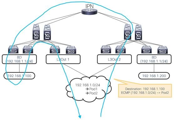
With the host route advertisement feature, each pod can advertise its local endpoints as /32 host routes on top of the bridge domain subnets. Then, the external routers can have host routes that point to a specific pod and avoid inefficient forwarding due to the bridge domain subnets as ECMP routes.
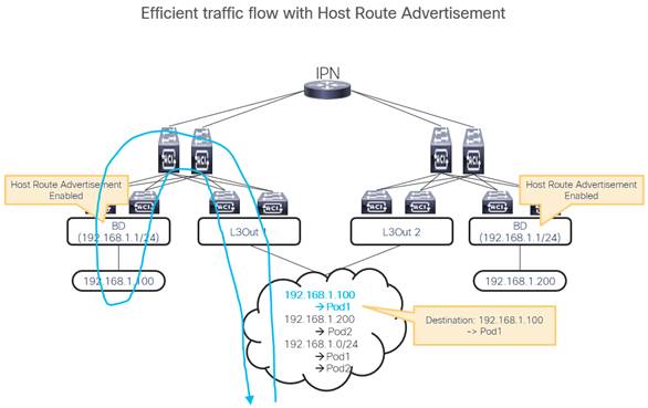
Host route advertisement can be enabled per bridge domain. On top of enabling this option in the bridge domain, configurations to advertise the bridge domain subnet such as route maps in the L3Out or L3Out to bridge domain association are required.
When using route maps, ensure to have an aggregate option in the IP address prefix-list so that not only the exact bridge domain subnet, but also the /32 host routes in the subnet can be advertised. At the time of this writing, when a per-peer BGP route map is used, the bridge domain to L3Out association is also required for the host route advertisement feature to work.
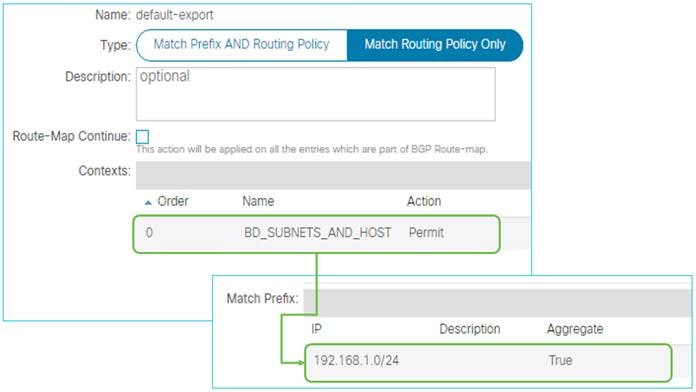
Starting from Cisco APIC release 4.1(1), host route advertisement is supported with Cisco ACI Multi-Site as well to avoid the same type of inefficient asymmetric traffic flow across sites.
Border leaf switches are Cisco ACI leaf switches that provide Layer 3 connections to outside networks. Any Cisco ACI leaf switch can be a border leaf switch. The border leaf switch can also be used to connect to computing, IP address storage, and service appliances. In large-scale design scenarios, for greater scalability, it may be beneficial to separate border leaf switches from the leaf switches that connect to computing and service appliances.
Border leaf switches support three types of interfaces to connect to an external router:
● Layer 3 (routed) interface
● Subinterface with IEEE 802.1Q tagging: With this option, multiple subinterfaces can be configured on the main physical interface, each with its own VLAN identifier.
● Switched virtual interface: With an SVI, the same physical interface that supports Layer 2 and Layer 3 can be used for Layer 2 connections as well as an L3Out connection.
In addition to supporting routing protocols to exchange routes with external routers, the border leaf switch applies and enforces policy for traffic between internal and external endpoints.
Cisco ACI supports the following routing mechanisms:
● Static routing (supported for IPv4 and IPv6)
● OSPFv2 for regular, stub, and not-so-stubby-area (NSSA) areas (IPv4)
● OSPFv3 for regular, stub, and NSSA areas (IPv6)
● EIGRP (IPv4 only)
● iBGP (IPv4 and IPv6)
● eBGP (IPv4 and IPv6)
Through the use of subinterfaces or SVIs, border leaf switches can provide L3Out connectivity for multiple tenants with one physical interface.
For design considerations related to using leaf switches for both the L3Out function and to connect servers to it, refer to the "Placement of outside connectivity / using border leafs for server attachment" section.
You can configure dynamic routing protocol peering over a vPC for an L3Out connection by specifying the same SVI encapsulation on both vPC peers, as illustrated in Figure 91. The SVI configuration instantiates a bridge domain, which in the figure has a VNID of 5555. The external router peers with the SVI on each leaf switch. In addition, the SVIs on the two leaf switches peer with each other.
If static routing to the fabric is required, you must specify the same secondary IP address on both vPC peer devices’ SVIs so that traffic from the external router towards Cisco ACI can be handled by both vPC peer leaf switches.
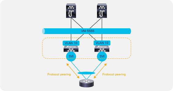
Additional design considerations are necessary when using a L3Out based on a vPC with more than two border leaf switches.
When SVI is used for L3Out, the SVI remains up even when all Layer 2 interfaces for the VLAN are down. As a result, static routes for the L3Out remains in the routing table even though the next-hop is not reachable. In such a case, the static routes are distributed to other leaf switches using MP-BGP and it looks as if the route is available from other leaf switches’ point of view. To avoid this scenario, SVI Auto State was introduced. When SVI Auto State is enabled, the SVI will go down when all of its Layer 2 interfaces go down. Refer to the L3Out Guide for details on this feature.
Some design scenarios may require gateway resiliency on the L3Out. For example, external services devices, such as firewalls, may require static routing to subnets inside the Cisco ACI fabric, as shown in Figure 92.
For L3Outs configured with static routing, Cisco ACI provides multiple options for a resilient next hop:
● Secondary IP: This option is available on routed interfaces, subinterfaces, and SVIs, but it is used primarily with SVIs.
● Hot Standby Routing Protocol (HSRP): This option is available on routed interfaces and on subinterfaces (and not on SVIs). It is used primarily in conjunction with an external switching infrastructure that helps ensure Layer 2 connectivity between the subinterfaces.
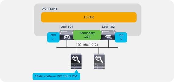
In the example in Figure 92, a pair of Cisco ASA firewalls (running in active/standby mode) are attached to the Cisco ACI fabric. On the fabric side, the L3Out is configured to connect to the firewalls. The Layer 2 connectivity for subnet 192.168.1.0/24 is provided by the Cisco ACI fabric by using SVIs with the same encapsulation on both leaf switches. On the firewalls, a static route exists pointing to internal Cisco ACI subnets through the 192.168.1.254 address. This .254 address is configured on the fabric as a shared secondary address under the L3Out configuration as shown in Figure 93.
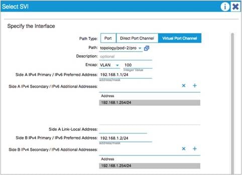
When configuring an SVI on an L3Out, you specify a VLAN encapsulation. Specifying the same VLAN encapsulation on multiple border leaf switches in the same L3Out results in the configuration of an external bridge domain.
Compared to a bridge domain inside the fabric, there is no endpoint database for the L3Out, and the forwarding of traffic at Layer 2 is based on flood and learn over VXLAN.
If the destination MAC address is the SVI MAC address, the traffic is routed in the fabric, as already described.
As explained in the "Limit the use of L3Out for Server Connectivity" section, the L3Out is meant primarily to attach routing devices including servers that run routing protocols. The L3Out is not meant to attach servers that exchange Layer 2 traffic directly on the SVI of an L3Out. Server interfaces that send Layer 2 traffic should be attached to EPGs and bridge domains.
There are multiple reasons for this:
● The Layer 2 domain created by an L3Out with SVIs is not equivalent to a regular bridge domain.
● The L3ext classification is designed for hosts that are multiple hops away.
Add L3Out SVI Subnets to the External EPG
When connecting devices to the L3Out, such as Layer 4 to Layer 7 devices, you should not just configure an L3ext of 0.0.0.0/0, but you should also add the L3Out SVI subnets. This is important if you have traffic destined to an IP address that is on the L3Out SVI; for instance, destined to the NAT address or the Virtual IP Address (VIP) of a firewall or load balancer. If you do not include the L3Out SVI, the IP addresses of the Layer 4 to Layer 7 service devices are assigned to class ID 1 instead of the L3ext class ID. In the specific case of traffic destined to an NAT or VIP address that belongs to the L3Out, if you did not add the L3Out SVI subnet to the L3ext, you may see that the traffic may be dropped even if a contract between the EPG and the L3ext is present.
Figure 94 illustrates this point.
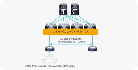
Bidirectional Forwarding Detection (BFD) for L3Out
Cisco ACI release 1.2(2g) added support for bidirectional forwarding detection (BFD) for L3Out links on border leaf switches. BFD is a software feature used to provide fast failure detection and notification to decrease the convergence times experienced in a failure scenario. BFD is particularly useful in environments where Layer 3 routing protocols are running over shared Layer 2 connections, or where the physical media does not provide reliable failure detection mechanisms.
With Cisco ACI versions prior to Cisco ACI 3.1(1), BFD can be configured on L3Out interfaces only, where BGP, OSPF, EIGRP, or static routes are in use.
From Cisco ACI release 3.1(1), BFD can also be configured between leaf and spine switches, and between spine switches and IPN links for GOLF, Cisco ACI Multi-Pod, and Cisco ACI Multi-Site connectivity to be used in conjunction with OSPF or with static routes.
Note: BFD for spine switches is implemented for cloud-scale line cards:
Cisco ACI uses the following implementations of BFD:
● BFD Version 1 is used.
● Cisco ACI BFD uses asynchronous mode. That is, both endpoints send hello packets to each other.
● BFD is not supported for multihop BGP.
By default, a BFD global policy exists for both IPv4 and IPv6 sessions. The default timers specified in this policy have a 50-millisecond interval with a multiplier of 3.
This global default policy can be overridden if required by creating a new non-default policy and assigning it to a switch policy group and then a switch profile.
BFD is also configurable on a per-tenant basis (under Networking > Protocol Policies) and will override the global BFD policy.
Enabling BFD on L3Out SVIs helps ensure fast failure detection, assuming that the connected device supports it. For routed interfaces and subinterfaces, BFD may still be enabled, although physical interface mechanisms should ensure fast failure detection in most circumstances.
The verified scalability guide provides the BFD session scale that has been tested per leaf switch: https://www.cisco.com/c/en/us/support/cloud-systems-management/application-policy-infrastructure-controller-apic/tsd-products-support-series-home.html#Verified_Scalability_Guides
This section provides a brief overview of the floating SVI functionality. Refer to the Using Floating L3Out to Simplify Outside Network Connections document for configuration details and limitations:
The floating SVI feature was introduced on Cisco ACI release 4.2(1) to solve the following problems:
● Virtual routers that dynamically move across hypervisor hosts: When an L3Out needs to establish protocol neighborship with virtual routers (such as Cisco CSR1Kv) or virtual firewalls, it is hard to predict which specific hypervisor host the router is deployed on or is going to move to because there are many solutions, such as VMware Distributed Resource Scheduler (DRS), that dynamically move the virtual workloads across hosts. In such scenarios, you would need to configure every possible switch interface where the virtual router may show up.
● Large number of router peers need to be configured: When a large number of virtual routers are deployed, such as virtual Packet Gateways (vPGW) in a 5G service provider setup. In such a case, not only the location of routers, but also the number of protocol sessions (typically BGP) becomes a problem. Although one could proactively provision the L3Out and neighbor configuration on all leaf switches, it would be inefficient.
The floating SVI feature can be used both with physical domains and VMM domains. Using the floating SVI feature with physical domains is useful when the virtual routers are on hypervisors without Cisco ACI VMM integration.
With floating SVIs, there are two types of border leaf switches:
● Anchor leaf switch – This is the leaf switch that has a unique IP address called the primary IP address that is dedicated to itself. With the primary IP address, each anchor leaf switch establishes a routing protocol neighborship with an external router. You must select the leaf switches to be anchor leaf switches.
● Non-anchor leaf switch – These are leaf switches to which the external bridge domain for the L3Out is expanded from the anchor leaf switches, but they don’t have a primary IP address. A virtual router can be neighbor with the primary IP addresses on the anchor leaf switches through a non-anchor leaf switch. Non-anchor leaf switches are selected based on the associated domain (physical or VMM).
With the non-anchor leaf switches expanding the Layer 2 reachability between the anchor leaf switch and the virtual router, virtual routers can freely move around across multiple leaf switches without having to configure L3Outs manually on all related leaf switches:
● When a VMM domain is used, Cisco ACI will dynamically detect the location of virtual routers and select non-anchor leaf switches and interfaces on which to deploy the VLAN.
● When a Physical domain is used, Cisco ACI will select all leaf switches without a primary IP address in the associated AAEP as non-anchor leaf switches and statically deploy the VLAN on all interfaces in the AAEP. However, you need to design your AAEP carefully so that the VLAN for the L3Out is not deployed on unnecessary interfaces.
On non-anchor leaf switches, you need to configure another IP address called the floating IP address that is common to all non-anchor leaf switches. This IP address is not meant to participate in routing protocols or static route configuration; hence you cannot use the floating IP address as a peer IP address for BGP or a static route next-hop. The floating IP address is used internally for ARP gleaning. When a leaf switch receives an ARP request to the IP address that is not yet resolved on the leaf switch in the external bridge domain for floating SVI, Cisco ACI performs ARP gleaning and non-anchor leaf switches will send ARP requests from the floating IP address to the target IP address to discover the router with the IP address. For this purpose, you need to have one IP address for floating IP address in the same subnet as primary IP addresses. On anchor leaf switches, the primary IP addresses are used for this purpose on top of the routing protocol.
With this architecture, the anchor leaf switch is essential for the floating SVI to work. The reason is because the routing protocols or static routes are configured on anchor leaf switches and the other leaf switches see the external routes as reachable from the anchor leaf switches even if the virtual router is behind one of the non-anchor leaf switches. Hence, the packets towards the virtual router will be forwarded to an anchor leaf switch first, then forwarded to the non-anchor leaf switch if the virtual router is behind a non-anchor leaf switch. On the other hand, the traffic from a virtual router does not go through an anchor leaf switch because it follows the regular forwarding mechanism with endpoint lookup and spine switch-proxy.
The following design recommendations apply:
● Configure at least two anchor leaf switches for redundancy.
● Use BFD or IP SLA tracking with static routing or dynamic routing protocols: When using static routing, if all anchor leaf switches go down, virtual routers on non-anchor leaf switches will not notice that the next-hop is down and will keep forwarding the traffic while Cisco ACI switches can no longer send traffic back to the virtual router. This may cause the traffic to be black-holed. By using BFD or IP SLA tracking with static routing or dynamic routing protocols the virtual router can detect the next-hop failure and use backup routes.
In a large scale deployments, such as a 5G service provider, establishing protocol neighborships with all routers may not be practical even if there are only a few (anchor) border leaf switches. The reason is because there could be hundreds of routers and all traffic will always go through an anchor leaf switch before it reaches the non-anchor leaf switch where the virtual router resides. The overhead with this suboptimal traffic is significant with a large number of routers.
In Cisco APIC release 5.0(1), a feature called BGP next-hop propagate was introduced to address this scenario. In fact, this feature has been designed to be used mainly in conjunction with floating SVI with the main goal of avoiding suboptimal traffic flows through a non-anchor leaf switch.
With the BGP next-hop propagate feature, you need only a few routers (control node or control function [CF]) establishing protocol neighborship with Cisco ACI. These control switches advertise routes with a common IP address instead of their own IP address as a next-hop. The common IP address is owned by the other routers that work as forwarding switches or service functions (SF).
With the BGP next-hop propagate feature in Cisco ACI, MP-BGP can ensure that the next-hop of the routes used by non-border leaf switches is the common IP address that is originally advertised as the next-hop by the external router, instead of the TEP IP address of the anchor leaf switch that learned the route from the external router.
Another Cisco ACI feature called direct attached host route advertisement (also known as interleak redistribution of a directly attached host) enables the non-border leaf switches to send the traffic to the actual border leaf switch, such as a non-anchor leaf switch in the case of floating SVI, that is connected to the router with the common IP address.
Check the Floating SVI config guide for details regarding next-hop propagate and direct attached host route advertisement.
Considerations for Multiple L3Outs
When configuring multiple connections from a border leaf switch, you can use either a single L3Out connection or multiple L3Out connections. In some environments, you might need to configure multiple L3Out connections in a single VRF, either with or without transit routing.
When deploying OSPF with a requirement for multiple networks, an administrator can choose to use either a single L3Out or separate L3Out instances for each connection.
An important point to consider is that the OSPF area is defined at the L3Out level. As a result, the following two rules apply:
● If you require the same border leaf switch to connect to multiple OSPF peer devices within the same area, you must use a single L3Out. You cannot configure multiple L3Out connections with the same OSPF area.
● If you require OSPF connections to two different areas from the same leaf switch, you must use separate L3Out connections . One of the L3Out connections must be part of area 0 in common with regular OSPF requirements.
External networks, also known as external EPGs, are used in L3Out configurations to define the external network destinations for the purposes of applying access controls (contracts). It is important to understand how this classification occurs and how this may affect security enforcement, particularly in an environment where multiple L3Out connections are associated with a single VRF and where overlapping external networks are configured.
External EPGs Have a VRF Scope
Even if Layer 3 external EPGs are under the L3out, when the VRF is configured for ingress filtering, Layer 3 external EPGs should be thought of as a per-VRF classification criteria.
The way the Layer 3 external EPG works is slightly different depending on whether the VRF is configured for ingress or egress filtering.
In the presence of multiple L3Outs and with VRF configured for ingress filtering, which is the default, the L3exts must be configured to be L3Out-specific by entering specific subnets instead of 0.0.0.0/0, or by having at the most one 0.0.0.0/0 L3ext.
If the VRF is configured with egress filtering instead, if the L3Outs are on different leaf switches, the L3ext of 0.0.0.0/0 would then be effectively referring to the specific L3Out where it is configured.
Consider the example shown in Figure 95.
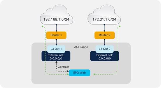
In this example, two L3Out connections are configured within the same VRF instance. The subnet 192.168.1.0/24 is accessible through one of the L3Out connections, and the subnet 172.31.1.0/24 is accessible through the other. From a Cisco ACI configuration perspective, both L3Out connections have an external network defined using the subnet 0.0.0.0/0. The desired behavior is to allow traffic between the Web EPG and the external network 192.168.1.0/24. Therefore, there is a contract in place permitting traffic between the Web EPG and L3Out 1.
This configuration has the side effect of also allowing traffic between the Web EPG and L3Out 2, even though no contract is configured for that communication flow. This happens because the classification takes place at the VRF level, even though external networks are configured under L3Out.
To avoid this situation, configure more specific subnets for the external EPGs under each L3Out, as shown in Figure 96.
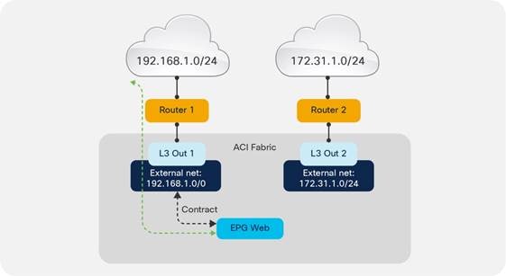
Figure 97 should help in understanding how to use the L3ext. The left of the figure shows how the L3ext is configured in Cisco ACI; it is under the L3Out. The right of the figure shows how you should think of the L3ext; that is, as a per-VRF configuration.
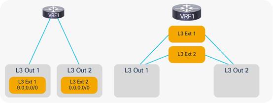
Using Dynamic L3Out EPG Classification (DEC)
When using multiple L3Outs, whenever possible, use the Dynamic L3Out EPG Classification (DEC) feature, which was introduced in Cisco ACI 5.2(4).
This feature allows you to define Layer 3 externals that are based on the subnets learned through dynamic routing. For instance, you can say that a subnet, such as 10.10.10.0/24, if learned through dynamic routing from a given L3Out should be associated with the external EPG called "ext-EPG1." Or, you could say that all subnets learned through dynamic routing from a given L3Out should be associated with a specific external EPG.
With this approach, if the route through a given L3Out disappears, the traffic may take the route through another L3Out for which you may have defined a different security policy (for instance, redirection to a firewall).
This feature also simplifies the configuration of multiple L3Outs. Consider Figure 97, where multiple L3Outs exist to different destinations. You may be configuring the Layer 3 external EPG with 0.0.0.0/0 under L3Out1 and L3Out2 to allow traffic from EPG1 to L3Out1 to go through the firewall and to L3Out2 directly.
The problem with using 0.0.0.0/0 is that traffic destined to 10.10.10.10.x may as well be classified as going to L3Out2 because of the fact that the 0.0.0.0/0 external EPG is not specific to L3Out2. You may then decide to define more specific external EPGs: one with 10.10.10.0/24 for L3Out1 and one with 20.20.20.0/24 with L3Out2. This configuration will work, but you need to know beforehand which routes are going to be available through L3Out1 and through L3Out2, which may be difficult to maintain. Furthermore 10.10.10.x reachability may change in the future, and a better route may appear through L3Out2, in which case going through the firewall should not be required any more. But, if 10.10.10.0/24 is defined in the external EPG for L3Out1, traffic destined to 10.10.10.x will still go through the firewall.
With DEC, instead of using 0.0.0.0/0 for both L3Outs, and instead of defining 10.10.10.0/24 for one L3Out and 20.20.20.0/24 for the other, you can simply define a default-import policy of type Match Prefix and Routing Policy on each L3Out with a match prefix list of 0.0.0.0/0 le 32 (Figure 98). The match prefix list of L3Out1 will have a set rule policy consisting of a route-map with set external EPG that assigns the subnets learned through L3Out1 to external EPG ext-epg1 and the subnets learned through L3Out2 to the external EPG ext-epg2. You do not need to enter any subnets under the external EPG (but you can), and you would define a contract as usual between the external EPG and the client EPG.
The result is that depending on the destination IP address, traffic from the client virtual machine (EPG1) will be assigned to the external EPG associated with the route that matches that destination IP address. With this configuration, even if you entered a prefix list of 0.0.0.0/0 le 32, there is no overlapping subnet because routes learned through L3Out1 are associated with a class-id that is different from the routes learned through L3Out2.
With the dynamic L3Out, you must configure the external EPG (with or without subnets defined) because the route-map set options assigns prefixes to one of the external EPGs that you defined.
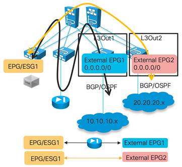
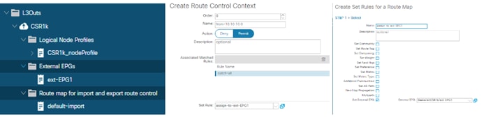
The dynamic L3Out EPG feature as of Cisco ACI 6.0(1) requires the use of BGP or OSPF. It does not work with EIGRP or with static routing.
For more information about the configuration and the caveats of the Dynamic L3Out refer to the following document:
Considerations When Using More Than Two Border Leaf Switches
Depending on the hardware used for the leaf switches and on the software release, the use of more than two border leaf switches as part of the same L3Out in Cisco ACI may have some limitations if these conditions are met:
● The L3Out consists of more than two leaf switches with the SVI in the same encapsulation (VLAN).
● The border leaf switches are configured with static routing to the external device.
● The connectivity from the outside device to the fabric is vPC-based.
This topology may not forward traffic correctly because traffic may be routed from one data center to the local L3Out and then bridged on the external bridge domain to the L3Out in another data center.
In Figure 100, the left side shows a topology that works with both first- and second-generation leaf switches. The topology on the right works with only Cisco Nexus 9300-EX and Cisco 9300-FX or later switches. In the topologies, Cisco ACI is configured for static routing to an external active/standby firewall pair. The L3Out uses the same encapsulation on all the border leaf switches to allow static routing from any border leaf switch to the active firewall. The dotted lines indicate the border leaf switches.
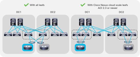
With topologies consisting of more than two border leaf switches, the preferred approach is to use dynamic routing and to use a different VLAN encapsulation for each vPC pair on the L3Out SVI. This approach is preferred because the fabric can route the traffic to the L3Out interface that has reachability to the external prefix without the need to perform bridging on an outside bridge domain. Figure 101 illustrates this point.
Figure 101 shows four border leaf switches: two in each data center. There are two L3Outs or a single L3Out that uses different VLAN encapsulations for data center 1 (DC1) and data center 2 (DC2). The L3Out is configured for dynamic routing with an external device.
For this design, there are no specific restrictions related to routing to the outside.
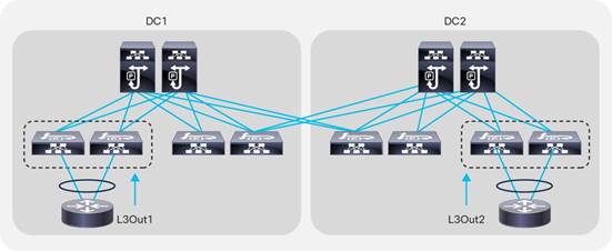
Using BGP for External Connectivity
BGP Autonomous System (AS) number
The Cisco ACI fabric supports one Autonomous System (AS) number. The same AS number is used for internal MP-BGP and for the BGP session between the border leaf switches and external routers. The BGP AS number is configured as described in the "BGP Route Reflector Policy" section.
An administrator can override the global AS number configuration using the local AS number found under the BGP peer connectivity profile when configuring each L3Out. This can be used if the administrator wants the Cisco ACI fabric to appear as a different AS number than the one configured globally. This configuration is shown in Figure 102.
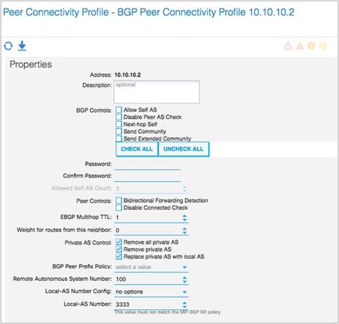
As with any other deployment running BGP, it is good practice to limit the number of AS paths that Cisco ACI can accept from a neighbor. This setting can be configured under Tenant > Networking > Protocol Policies > BGP > BGP Timers by setting the Maximum AS Limit value.
External prefixes learned by an L3Out may or may not be automatically redistributed to MP-BGP, depending on the configuration of the Route Control Enforcement import option in the L3Out. If L3Out Route Control Enforcement is not selected, all networks learned from the outside are redistributed to MP-BGP. You can control which routes are imported if, under L3Out, you choose the Route Control Enforcement option and select Import. This option applies to OSPF, EIGRP, and BGP.
You can specify the prefixes that are redistributed by configuring the default import route profile under the L3Out.
Note: You can also define which routes are imported by configuring subnets under the Layer 3 external network and selecting Import Route Control Subnet for each network. This configuration is a specific match. That is, a match of the prefix and prefix length.
Support for route summarization was introduced in Cisco ACI release 1.2(2) for BGP, EIGRP, and OSPF routing protocols. Summarization in Cisco ACI has the following characteristics:
● Route summarization occurs from the border leaf switches. Summaries are never carried inside the fabric.
● Summarization works for both tenant (bridge domain) routes and transit routes.
● Summary routes are installed in the routing table as routes to Null0.
Although there are some slight variations depending on the routing protocol in use, the general configuration method for route summarization is to configure a subnet entry in the External Networks section of the L3Out configuration. The configured subnet should be the actual summary address you wish to advertise. Additionally, the Route Summarization Policy (OSPF and BGP) or Route Summarization (EIGRP) option must be selected, along with the Export Route Control option.
The configurations for BGP, OSPF, and EIGRP summarization are shown in Figure 103, Figure 104, and Figure 105.
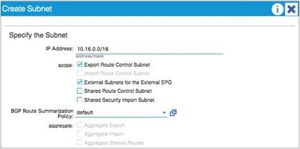
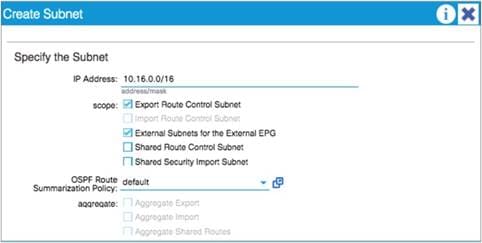
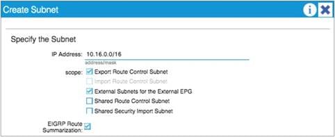
For BGP summarization, the AS-SET option can be configured. This option instructs Cisco ACI to include BGP path information with the aggregate route. If AS-SET is required, create a new BGP summarization policy, select the AS-SET option, and then associate this policy under the External Network configuration. Figure 106 shows the configuration of the AS-SET option under the BGP summarization policy.
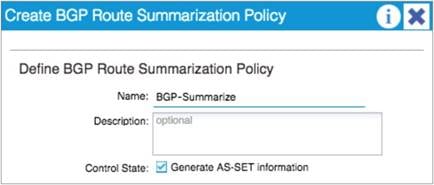
For OSPF route summarization, two options are available: external route summarization, which is equivalent to the summary-address configuration in Cisco IOS® Software and Cisco NX-OS Software, and inter-area summarization, which is equivalent to the area range configuration in Cisco IOS Software and Cisco NX-OS.
When tenant routes or transit routes are injected into OSPF, the Cisco ACI leaf switch where the L3Out resides acts as an OSPF Autonomous System Boundary Router (ASBR). In this case, use the summary-address configuration (that is, the external route summarization). This concept is shown in Figure 107.
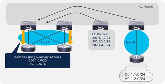
For scenarios where there are two L3Outs, each using a different area and attached to the same border leaf switch, the area range configuration will be used to summarize, as shown in Figure 108.
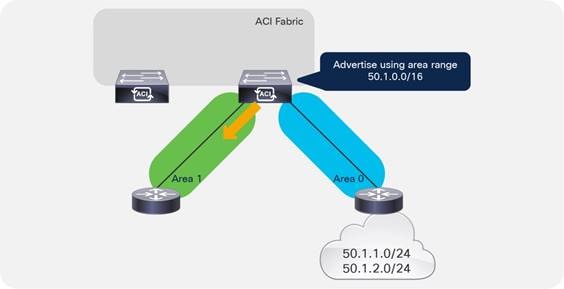
The OSPF route summarization policy is used to determine whether the summarization will use the area range or the summary-address configuration, as shown in Figure 109.
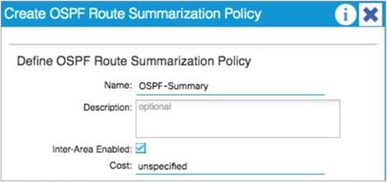
In the example in Figure 109, putting a check in the Inter-Area Enabled box means that area range will be used for the summary configuration. If this box is unchecked, summary-address will be used.
Starting from Cisco ACI release 5.0(1), Cisco ACI L3Out supports Segment Routing – Multi Protocol Label Switching (SR-MPLS) or MPLS on a border leaf switch. One of the main advantages of this feature is that border leaf switches can exchange prefixes for all VRF instances with one BGP-EVPN session with the external router such as PE (provider edge) facing data center (DC-PE).
This feature is suited for service providers where slicing of the network with a large number of VRF instances is required and all VRF instances need to exchange their routes with external routers. Doing this with a regular L3Out configuration requires routing protocol sessions for each VRF, hence the amount of configuration and overhead may grow significantly. With MPLS, you only need one MPLS infra L3Out to exchange all routes using BGP-EVPN.
With SR-MPLS/MPLS, a border leaf switch exchanges routes along with labels corresponding to each VRF using a single BGP-EVPN session with an external router. Then, traffic is forwarded between the border leaf switch and external routers with a label encapsulation corresponding to each VRF.
There are similarities and differences with GOLF:
● GOLF uses VXLAN VNIDs to represent VRF instances
● SR-MPLS/MPLS uses MPLS labels to represent VRF instances
● Both GOLF and SR-MPLS/MPLS use BGP-EVPN to exchange routes and VRF information
Refer to the Cisco ACI SR/MPLS Handoff Architecture White Paper for more information:
The transit routing function in the Cisco ACI fabric enables the advertisement of routing information from one L3Out to another, allowing full IP address connectivity between routing domains through the Cisco ACI fabric. The configuration consists of specifying which of the imported routes from an L3Out should be announced to the outside through another L3Out, and which external EPG can talk to which external EPG. You specify this configuration through the definition of contracts provided and consumed by the external network under the L3Out.
To configure transit routing through the Cisco ACI fabric, you need to allow the announcement of routes either by configuring the route profiles (default export and default import) or by marking the subnets in question with the Export Route Control option when configuring external networks under the L3Out. An example is shown in Figure 110.
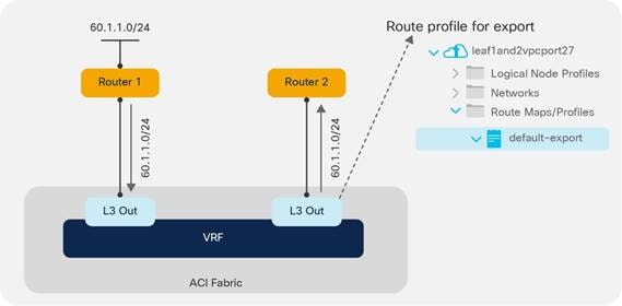
In the example in Figure 110, the desired outcome is for subnet 60.1.1.0/24, which has been received from Router 1, to be advertised through the Cisco ACI fabric to Router 2. To achieve this, the 60.1.1.0/24 subnet must be defined on the second L3Out and allowed through a route profile. This configuration will cause the subnet to be redistributed from MP-BGP to the routing protocol in use between the fabric and Router 2.
It may not be feasible or scalable to define all possible subnets individually as export route control subnets. It is therefore possible to define an aggregate option that will mark all subnets for export. An example is shown in Figure 111.
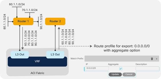
In the example in Figure 111, there are a number of subnets received from Router 1 that should be advertised to Router 2. Rather than defining each subnet individually, the administrator can define the 0.0.0.0/0 subnet and set the Aggregate option. This option instructs the fabric that all transit routes should be advertised from this L3Out.
Note: The Aggregate option does not actually configure route aggregation or summarization; it is simply a method to specify all possible subnets as exported routes.
In some scenarios, you may need to export static routes between L3Outs, as shown in Figure 112.
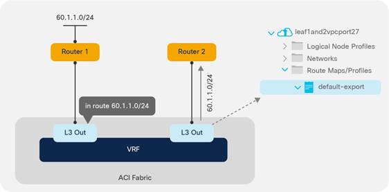
In the example in Figure 112, there is a static route to 60.1.1.0 configured on the left L3Out. If you need to advertise the static route through the right L3Out, you must specify a route profile to allow it.
Supported Combinations for Transit Routing
Some limitations exist on the supported transit routing combinations through the fabric. In other words, transit routing is not possible between all possible routing protocols.
The latest matrix showing supported transit routing combinations is available in the following document:
https://www.cisco.com/c/en/us/td/docs/switches/datacenter/aci/apic/sw/kb/b_KB_Transit_Routing.htmlhttps://www.cisco.com/c/en/us/td/docs/dcn/aci/apic/5x/l3-configuration/cisco-apic-layer-3-networking-configuration-guide-51x/m_transit_routing_v2.html
Loop Prevention in Transit Routing Scenarios
When the Cisco ACI fabric advertises routes to an external routing device using OSPF or EIGRP, all advertised routes are tagged with the number 4294967295 by default. For loop-prevention purposes, the fabric will not accept routes inbound with the 4294967295 tag. This may cause issues in some scenarios where tenants and VRF instances are connected together through external routing devices, or in some transit routing scenarios, such as the example shown in Figure 113.
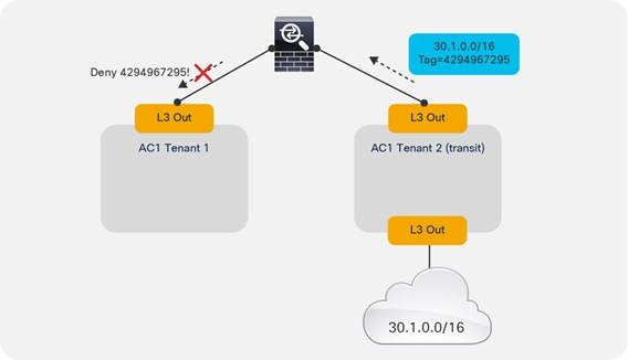
In the example in Figure 113, an external route (30.1.0.0/16) is advertised in Cisco ACI Tenant 2, which is acting as a transit route. This route is advertised to the firewall through the second L3Out, but with a route tag of 4294967295. When this route advertisement reaches Cisco ACI Tenant 1, it is dropped due to the tag.
To avoid this situation, the default route tag value should be changed under the tenant VRF instance, as shown in Figure 114.
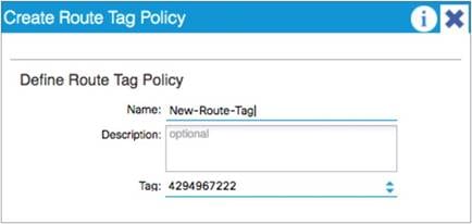
Quality of Service (QoS) In Cisco ACI
In releases of Cisco ACI up to and including 3.2, there are three user-configurable QoS classes: Level1, Level2, and Level3.
Cisco ACI release 4.0 uses six different user-configurable qos-groups to prioritize the traffic and four internally reserved qos-groups.
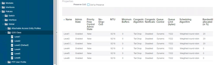
You can tune the user configurable qos-groups configurations from the Fabric Access Policies > Policies > Global Policies > QOS Class (see Figure 115). By default, the traffic from a tenant EPG is mapped to the Level 3 class regardless of the CoS of the original packet.
The DSCP value of the original packet (that is, the inner DSCP value) is normally not modified, and is not mapped to the outer VXLAN header either. You can remark the DSCP of the original packet by configuring "Custom QoS" under the EPG or as part of the contract configuration by configuring the target CoS or the target DSCP values as part of the Custom QoS configuration.
The classification of the traffic to the QoS group or level is based either on the DSCP or dot1p values of the traffic received from the leaf switch front panel ports (Custom QoS policy under the EPG), or on the contract between EPGs (QoS Class under the contract), or on the source EPG (QoS Class under the EPG).
If in the Custom QoS configuration there is a match of both the DSCP and CoS values, the classification based on the DSCP value takes precedence.
If the EPG does not have a specific QoS policy configured, the traffic is assigned to the Level 3 class (the default QoS Class).
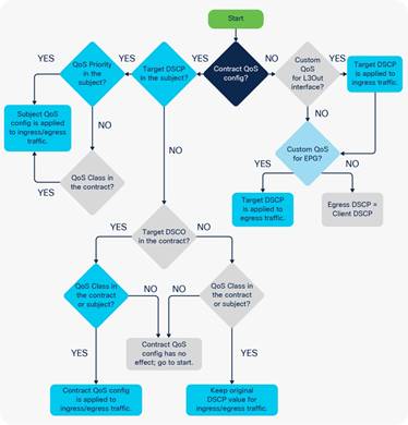
If the Fabric Access Policies > Policies > Global Policies > QOS Class dot1p preservation knob is set, the VXLAN DSCP header that is used within the fabric and on an IPN, if you carry this traffic on a routed network between PODs, carries both the information about the original Class of Service from the incoming packet and the QoS class level (qos-group) of the EPG. This ensures that, when the traffic leaves the fabric from an EPG, the CoS of the packet is set to the same value as the original frame, unless you configured a Custom QoS policy to overwrite it.
If dot1p preserve is configured, the incoming traffic is assigned to the QoS group or level based on the EPG configuration, but the original CoS is maintained across the fabric.
If dot1p preserve is configured and custom QoS is configured without a target CoS value, the original CoS is preserved. If instead the configuration specifies a target CoS, then the CoS is rewritten to the target CoS.
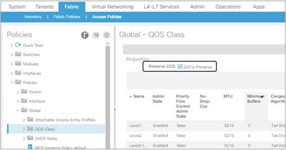
Quality of Service for Traffic Going to an IPN
The term Inter-Pod Network (IPN) refers to the routed network used to interconnect Cisco ACI pods.
If you are planning to use Cisco ACI Multi-Pod, Cisco ACI Multi-Site, or GOLF, you may have to tune the tenant "infra" Quality of Service configuration. This is because, when using Cisco ACI Multi-Pod, Cisco ACI Multi-Site, or GOLF, the fabric VXLAN-encapsulated traffic is carried across an IPN network, and the traffic must be correctly prioritized.
It is outside the scope of this document to discuss best practices related to Cisco ACI Multi-Pod and Cisco ACI Multi-Site, but for completeness you must understand some key QoS points about the underlay transport in Cisco ACI. For more information, refer to the following documents:
● http://www.cisco.com/c/en/us/td/docs/switches/datacenter/aci/apic/sw/kb/b_Multipod_QoS.html
Often, network switches that may be used in the IPN set the CoS of the traffic based on the DSCP values of the outer VXLAN header, and the receiving spine switch in a different pod uses either the CoS or the DSCP value to associate the traffic with the correct queue in Cisco ACI. With default configurations, the spine switches receiving traffic from the IPN network assign either DSCP CS6 or CoS 6 to a special QoS class used by Cisco ACI for traceroute; therefore, if regular traffic received on a spine switch from the IPN is tagged with DSCP CS6 or CoS 6, it may be dropped.
The main potential disadvantage of "dot1p preserve" is that if you need to configure QoS on the IPN by matching the DSCP values of the VXLAN header, you need to know how CoS and internal Cisco ACI QoS classes are mapped to the DSCP header, and you cannot change which DSCP value is used for what. This can be tricky if you need the flexibility to assign Cisco ACI traffic to a DSCP class selector that is not already in use.
As an example, if the IPN is used to connect to GOLF for north-to-south traffic and also for pod-to-pod connectivity, there may be north-to-south traffic with an outer VXLAN header of DSCP CS6. The inner DSCP header may be copied by GOLF devices to the outer VXLAN header. You may then need to choose DSCP class selectors for pod-to-pod control plane traffic that does not overlap with the DSCP values used for north-to-south traffic.
If, instead of using dot1p preserve, you configure Cisco ACI tenant "infra" translations, you can map the Cisco ACI qos-group traffic to specific DSCP values for the outer VXLAN header. By doing this, you can choose DSCP values that are not already used by other traffic types.
Figure 118 shows how to configure qos-group to DSCP translation for tenant "infra". This is normally done by configuring the tenant "infra" > Policies, Protocol Policies > DSCP class-cos translation policy.
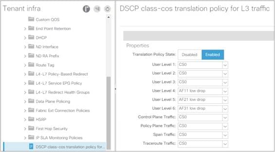
The following design guidelines apply:
● You should configure either dot1p preserve or tenant "infra" translation policies, but not at the same time.
● Be aware that CoS 6 and DSCP CS6 values are normally reserved for traceroute traffic, so normally you should ensure that Cisco ACI spine switches do not receive from the IPN any traffic with CoS 6 or DSCP CS 6.
● Cisco ACI release 4.0 introduces more user-configurable qos-groups and the new encoding of these qos-groups into the outer DSCP header. Because of this, when upgrading from Cisco ACI 3.x to Cisco ACI 4.0 in presence of a transit NX-OS fabric, traffic between pods may not always be consistently classified.
VRF Sharing Design Considerations
A common requirement of multitenant cloud infrastructures is the capability to provide shared services to hosted tenants. Such services include Active Directory, DNS, and filers. Figure 119 illustrates this requirement.
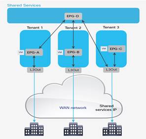
In Figure 119, Tenants 1, 2, and 3 have locally connected servers, respectively part of EPGs A, B, and C. Each tenant has an L3Out connection connecting remote branch offices to this data center partition. Remote clients for Tenant 1 need to establish communication with servers connected to EPG A. Servers hosted in EPG A need access to shared services hosted in EPG D in the tenant called "Shared Services." EPG D provides shared services to the servers hosted in EPGs A and B and to the remote users of Tenant 3.
In this design, each tenant has a dedicated L3Out connection to the remote offices. The subnets of EPG A are announced to the remote offices for Tenant 1, the subnets in EPG B are announced to the remote offices of Tenant 2, and so on. In addition, some of the shared services may be used from the remote offices, as in the case of Tenant 3. In this case, the subnets of EPG D are announced to the remote offices of Tenant 3.
Another common requirement is shared access to the Internet, as shown in Figure 120. In the figure, the L3Out connection of the Shared Services tenant (L3Out 4) is shared across Tenants 1, 2, and 3. Remote users may also need to use this L3Out connection, as in the case of Tenant 3. In this case, remote users can access L3Out 4 through Tenant 3.
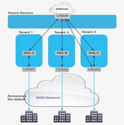
These requirements can be implemented in multiple ways:
● Use the VRF instance from the common tenant and the bridge domains from each specific tenant, as described in the "VRFs in the common tenant and bridge domains in user tenants" section.
● Use the equivalent of VRF leaking, which with Cisco ACI can be implemented in two different ways depending on whether you are using EPGs or ESGs.
● Provide shared services by connecting external routers to the Cisco ACI tenants and using external routers to interconnect tenants.
● Provide shared services from the Shared Services tenant by connecting it with external cables to other tenants in the fabric.
The first two options don’t require any additional hardware beyond the Cisco ACI fabric itself. The third option requires external routing devices, such as additional Cisco Nexus 9000 series switches, that are not part of the Cisco ACI fabric. If you need to put shared services in a physically separate device, you are likely to use the third option.
The fourth option, which is logically equivalent to the third one, uses a tenant as if it were an external router and connects it to the other tenants through loopback cables. If you have a specific constraint that makes the first two options not viable, but if you don’t want to have an additional router to manage, then most likely you will want to use the fourth option.
Inter-Tenant and Inter-VRF Communication
In a Cisco ACI fabric, you can configure communication between tenants, as well as communication between VRF instances within a tenant, using the constructs available within the fabric. That is, avoiding the use of an external routing or security device to route between tenants and VRF instances. This approach is analogous to VRF route leaking within a traditional routing and switching environment.
The configurations for route-leaking and class ID derivation are intertwined, hence the configuration for route leaking and the configuration for traffic filtering are combined. With the feature called Endpoint Security Groups (ESG), these two capabilities are decoupled.
For inter-VRF (and inter-tenant) traffic to flow, two factors must be addressed. First, routes must be leaked between the two VRF instances in question. Second, the fabric must allow the communication based on the class ID field carried in the VXLAN header. The class ID normally has a locally significant value, but in certain configurations, such as with VRF-to-VRF traffic, Cisco ACI must use a global class ID that is unique in the fabric.
Inter-VRF Communication using EPGs
When using EPGs for VRF sharing, both the control plane element and the dataplane filtering are configured using the EPGs themselves and contracts. When a consumer EPG is attached to a contract, the bridge domain subnet of that consumer EPG will automatically be leaked to the provider EPG’s VRF. For the provider-side subnet to be leaked to the consumer VRF instance, the same subnet as the bridge domain or a more specific one must also be configured at the provider EPG level and marked as shared.
The example in Figure 121 shows a scenario where communication must occur between two EPGs across different VRF instances within the same tenant.
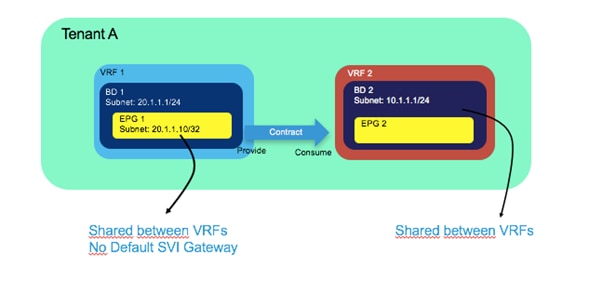
In the scenario in Figure 121, EPG 1 is providing a contract, which EPG 2 is consuming it. The following list includes the main points about the configuration of inter-VRF communication:
● The scope of the contract used for the inter-VRF communication must be set to either Tenant or Global.
● You need to configure a subnet under the provider EPG with the "Shared between VRFs" scope set and "no default gateway SVI."
● The consumer BD subnet scope must be set with "Shared between VRFs."
The bridge domain subnet scope "Shared between VRFs" is disabled by default, which means the bridge domain subnet is not leaked to other VRF instances. To leak the consumer bridge domain subnet to the provider VRF, the consumer bridge domain subnet scope must be "Shared between VRFs." The configuration is located at Tenant > Networking > Bridge Domains > Consumer_BD_name > Subnets.
In the example in Figure 121, the provider EPG is configured with the IP address of the endpoint providing the shared service. Even if the VRF instances are set to Unenforced mode, you will still need to configure a contract between the provider and consumer EPGs for route leaking to occur.
The second example (shown in Figure 122) is for a scenario where communication between VRF instances residing in different tenants is required.
The primary design and configuration difference between intra-tenant contracts and inter-tenant contracts is the "visibility" of the contract from both tenants: the contract object must be visible in both tenants.
There are two ways for a contract to be visible to both tenants:
● The contract is defined in tenant common and hence it is visible to all tenants.
● The contract is defined in a user tenant and "exported" to a different tenant using the configuration called "contract interface."
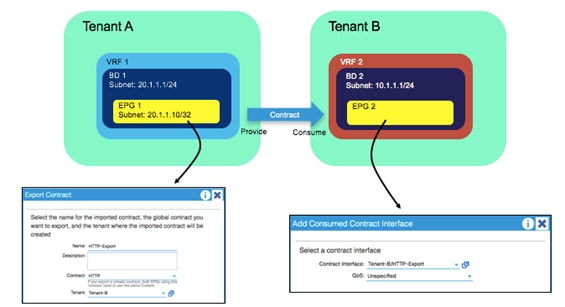
In the scenario shown in Figure 122, the main difference from the inter-VRF example is that a global contract must be exported from Tenant A.
On the EPG configuration within Tenant B, the contract is added as a consumed contract interface, selecting the contract that was previously exported. All other configurations, such as the subnet under EPG and the bridge domain, are identical to the configurations shown in the inter-VRF example.
Note You can find more information about Inter-Tenant contracts and Inter-VRF contracts in the following document: https://www.cisco.com/c/en/us/solutions/collateral/data-center-virtualization/application-centric-infrastructure/white-paper-c11-743951.html
Inter-VRF Communication using ESGs
With ESGs the route leaking configuration is decoupled from the traffic filtering configuration, as a result there is no need to configure the Bridge Domain with the Subnet defined as “Shared between VRFs”, nor there is the need to configure a Subnet under the provider EPG.
When using ESGs the VRF sharing configuration is divided into two parts:
● The route leaking configuration which is achieved by configuring Tenant > Networking > VRF > Inter-VRF Leaked Routes
● The traffic filtering configuration which is performed by configuring ESGs and contracts
The route leaking configuration is further subdivided into two options:
● Leaking of BD Subnets: Tenant > Networking > VRF > Inter-VRF Leaked Routes > EPG/BD Subnets where you specify the Subnet that you want to leak from this VRF, to which Tenant and VRF it should be leaked and whether this route can be announced to the outside via a L3Out
● Leaking of external routes learned from a L3Out: Tenant > Networking > VRF > Inter-VRF Leaked Routes > External Prefixes where you specify with an IP prefix-list which routes you want to leak from this VRF, to which Tenant and VRF it should be leaked
The traffic filtering configuration consists of a normal ESG-to-ESG contract. ESGs, differently from EPGs always have a global class-id regardless of whether route leaking is configured or not.
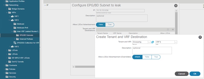
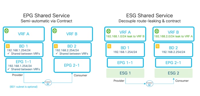
Configuration of the Subnet: When to Enter the Subnet Under the EPG
The general guidance is that a subnet used as the default gateway for servers should always be configured at the bridge domain level even for the provider-side configuration.
This section aims to clarify the purpose of placing subnets under the EPG, which is necessary for Inter-VRF route leaking when not using ESGs.
Cisco ACI optimizes route leaking between VRF instances by leaking the routes of the provider side only for EPGs that provide shared services. All subnet routes of the consumer-side bridge domain are instead leaked to the provider-side VRF instance.
A bridge domain can contain multiple subnets, so Cisco ACI must know which of the provider-side subnets should be leaked to the consumer VRF instance. For this optimization to occur, the subnets or the /32 that you enter on the provider-side EPG is leaked on the consumer-side VRF instance.
The definition of a subnet under the provider-side EPG is used only for the purpose of VRF leaking. You should configure this subnet not to provide the default gateway function by selecting the option No Default SVI Gateway. The subnet defined under the bridge domain is the default gateway for the servers on the provider-side EPGs.
In presence of VRF leaking, the classification information of which endpoint belongs to which EPG must be carried across VRF instances. To optimize resource usage, Cisco ACI looks up traffic in the policy CAM table with the scope set to the consumer-side VRF only. This means that traffic filtering for provider EPG to consumer EPG and for the opposite direction happens in the context of the consumer-VRF. The classification information of the endpoints that belong to the provider-side VRF is then based on the subnet information that you enter in the provider-side EPGs.
The subnet defined on the provider-side EPG should be non-overlapping with other subnets defined in the EPGs in the same bridge domain because the IP address specified in the EPG is used to derive the destination class ID when cross-VRF forwarding is performed.
Figure 125 illustrates this configuration.
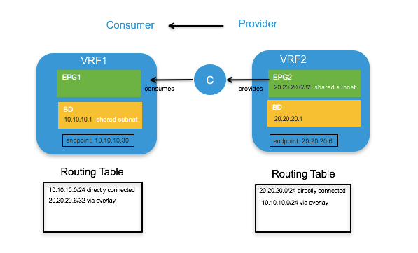
The subnet 20.20.20.6/32 defined under the provider EPG is configured as shared. The default gateway for the server 20.20.20.6 is the bridge domain subnet 20.20.20.1.
Note: If that subnet must also be announced to an L3Out connection, it should also be configured as advertised externally.
You need to make sure that all EPGs in VRF2 use disjoint subnets. For instance, if EPG2 is defined with 20.20.20.1/24 as a subnet, another EPG, such as EPG3 under VRF2, cannot also use 20.20.20.1/24. Otherwise, when traffic from the consumer-side VRF is destined to endpoints in the provider-side VRF with an address in the 20.20.20.x range, Cisco ACI would not know which provider-EPG they need to be associated with because all EPGs from the provider VRF would share the same subnet.
It is a common approach for each tenant and VRF residing in the Cisco ACI fabric to have its own dedicated L3Out connection. However, an administrator may wish to use a single L3Out connection that can be shared by multiple tenants within the Cisco ACI fabric. This allows a single L3Out connection to be configured in a single, shared tenant (such as the common tenant), with other tenants on the system sharing this single connection, as shown in Figure 126.
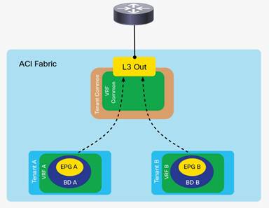
A shared L3Out configuration is similar to the inter-tenant communication discussed in the previous section. The difference is that in this case, the routes are being leaked from the L3Out connection to the individual tenants, and vice versa. Contracts are provided (or consumed) between the L3ext in the shared tenant and consumed (or provided) by the EPG/ESGs in the individual tenants.
The L3Out connection can be defined as usual in the shared tenant. This tenant can be any tenant, not necessarily the common tenant. The external network should be defined as usual.
The configuration is slightly different depending on whether the contract is between an external EPG and an EPG or between an external EPG and an ESG:
● If you configure a contract between an external EPG and a regular EPG, the external EPG subnet must be configured with Shared Route Control Subnet and Shared Security Import Subnet. This means that the routing information from this L3Out connection can be leaked to other tenants, and subnets accessible through this L3Out connection will be treated as external EPGs for the other tenants sharing the connection (Figure 126).
● If you configure a contract between an external EPG and an ESG, the external EPG subnet has to be configured with Shared Security Import Subnet because the control plane configuration for route leaking is configured at Tenant > Networking > VRF > Inter-VRF Leaked Routes > External Prefixes.
Further information about these options is as follows:
● Shared Route Control Subnet: This option indicates that this network, if learned from the outside through this VRF, can be leaked to other VRF instances, assuming that they have a contract with the external EPG.
● Shared Security Import Subnets: This option defines which subnets learned from a shared VRF belong to this external EPG for the purpose of contract filtering when establishing a cross-VRF contract.
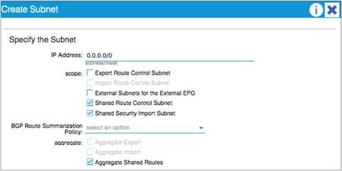
In the example in Figure 127, the Aggregate Shared Routes option is enabled. This means that all routes will be marked as Shared Route Control. In other words, all routes will be eligible for advertisement through this shared L3Out connection.
If the external EPG of the shared L3Out is a consumer of the contract provided by an EPG, the subnets defined under bridge domains should be marked as both Advertised Externally and Shared Between VRFs, as shown in Figure 128.
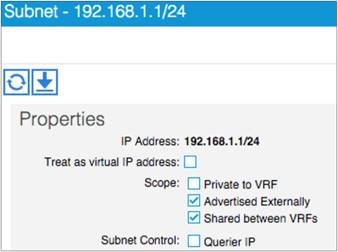
This configuration is not necessary when the provider of the contract is an ESG because the route leaking configuration that announces the bridge domain subnets is configured in Tenant > Networking > VRF > Inter-VRF Leaked Routes > EPG/BD Subnets.
The following figure illustrates the difference of configuration between a shared L3Out that is the provider of a contract with an EPG or with an ESG.
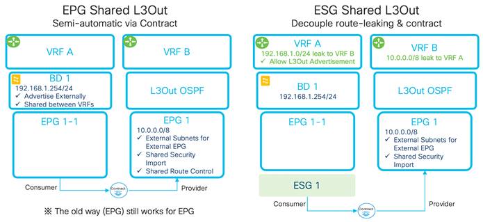
For more information about the Shared L3Out, see the following document:
https://www.cisco.com/c/en/us/solutions/collateral/data-center-virtualization/application-centric-infrastructure/guide-c07-743150.html#L3OutsharedserviceVRFrouteleaking
Policy Enforcement with Inter-VRF Traffic
The "Ingress versus Egress Filtering design considerations" section discusses the use of the option VRF "ingress" versus the option "egress." The following table illustrates where the policy is enforced with inter-VRF contracts:
Table 14 Ingress versus Egress filtering and hardware resources
| Scenario |
VRF enforcement mode |
Consumer |
Provider |
Policy enforced on |
| Inter VRF |
Ingress/egress |
EPG |
EPG |
Consumer leaf switch |
| Ingress/egress |
EPG |
L3out EPG (L3ext) |
Consumer leaf switch |
|
| Ingress/egress |
L3out EPG (L3ext) |
EPG |
Ingress leaf switch |
|
| Ingress/egress |
L3out EPG (L3ext) |
L3out EPG (L3ext) |
Ingress leaf switch |
With ESGs, both VRF instances leak their subnets to the other one, this means that contracts are applied on the egress VRF. On the egress VRF, a leaf node can get the source pcTag from the VxLAN header of the actual packets from the ingress VRF.
Special Considerations and Restrictions for VRF Sharing Designs
When using VRF sharing, Cisco ACI configures the VRF instances for policy-CAM filtering in ways that are optimizing the policy-CAM utilization as well as implementing security so that only EPGs that have a contract are allowed to talk. As mentioned in the previous section, the policy filtering is implemented in the consumer VRF, and in the provider VRF, Cisco ACI programs policy-CAM rules to allow traffic to the consumer VRF. You can find more details about the implicit rules that Cisco ACI programs for this purpose in the "How a contract works for intra-VRF traffic" section of the following document:
You need to be aware of the implicit rules created for inter VRF policy-CAM filtering especially when you use vzAny or preferred groups because some rules that are implicitly created may have priorities that are potentially higher than the vzAny or preferred groups rules.
You should use the following guidelines:
● Do not configure EPGs of different VRF instances to provide and consume the same global contract because the Cisco ACI logic for programming the policy CAM is optimized for configurations where between the EPGs there’s a clear provider EPG and a clear consumer EPG, which in turn define which VRF is provider and which VRF is consumer for that EPG pair.
● An EPG in a preferred group can consume an inter-VRF contract, but cannot be a provider for an inter-VRF contract with a L3Out EPG as the consumer because the implicit policy-cam entries used for inter-VRF contracts have priorities that are similar or higher than the implicit permit rules created by the preferred group feature
There are mainly two components to upgrade in a Cisco ACI fabric: Cisco APICs and switches. When performing these upgrades, the most basic recommendations are to check the following tool and documents:
● Upgrade Support Matrix: https://www.cisco.com/c/dam/en/us/td/docs/Website/datacenter/apicmatrix/index.html. This tool lists the supported upgrade path. When the target version and the current version are too far away, upgrading directly to the target version may not be supported. Such upgrades may. Always make sure to check the supported upgrade path.
● Upgrade Best Practices: https://community.cisco.com/t5/data-center-documents/aci-upgrade-preparation-best-practice-and-troubleshooting/ta-p/3211109. This document explains common mistakes and things that are recommended to check prior to the upgrade to avoid any known issues.
● Installation, Upgrade and Downgrade guide: https://www.cisco.com/c/en/us/td/docs/switches/datacenter/aci/apic/sw/all/apic-installation-upgrade-downgrade/Cisco-APIC-Installation-Upgrade-Downgrade-Guide.html. This document is a configuration guide for upgrades of Cisco ACI fabric. It covers not only the pre-upgrade validations mentioned above, but also the explanation of the upgrade configuration workflow and supported operations with mixed versions for the time when the upgrade of all switches cannot be finished in one maintenance window.
● Cisco ACI Upgrade Checklist: https://www.cisco.com/c/en/us/td/docs/switches/datacenter/aci/apic/sw/kb/Cisco-ACI-Upgrade-Checklist.html. This document provides a checklist of actions that you should take before and during the upgrade process, as well as links to relevant documentation.
In newer releases, Cisco APIC performs some pre-upgrade validation and warns you about some faults or configurations that are known to cause issues or traffic disruption with upgrades. When you see such warnings, always make sure to check them thoroughly. Refer to the Installation Guide for the validations added in later versions.
When performing upgrades, the Cisco APICs should be upgraded first, then switches. The following sections describe considerations for an upgrade.
Cisco APIC upgrades should be performed only when the Cisco APIC cluster is fully-fit. During a Cisco APIC upgrade, do not reboot, decommission, change the cluster size or initialize the Cisco APICs. You may be tempted to do so because, prior to Cisco ACI 4.2(5), the installation process didn’t provide details and some may have thought that the Cisco APICs were stuck since the progress percentages didn’t change. However, performing such operations will likely make the situation worse even if a Cisco APIC actually got stuck by any chance. In such a case, contact Cisco TAC immediately before performing the operations mentioned above.
Reducing the Cisco APIC Upgrade Time
If your fabric has been running for a long time, the number of record objects, such as audit long (aaaModLR), events (eventRecord), and fault history (faultRecord), may have grown significantly. This may cause Cisco APIC upgrades to take longer. In such a case, you can change the setting for record objects to reduce the maximum size. In case you increased the maximum record size in the past and suffered with the time Cisco APIC takes to finish upgrades, you may want to consider changing the size back to the default.
Cisco ACI switches are upgraded through the Cisco APIC. Create a group of switches with a target firmware version, then trigger the upgrade of the switches as a group using the Cisco APIC.
When an upgrade is performed for a switch, the following is the basic workflow of what happens.
1. The switch downloads the target firmware image from a Cisco APIC.
2. The switch waits for an approval from a Cisco APIC to start the upgrade.
3. The switch prepares for the upgrade.
4. The switch reboots.
5. The switch boots up and join the fabric.
Prior to Cisco ACI release 4.0(1), there were two switch groups to be configured for upgrades:
● The firmware group specifies the target firmware version for switches listed in the group.
● The maintenance group triggers the upgrade for switches listed in the group.
This tends to be an unnecessary flexibility because there should be no situation where you want to have two types of groups for the same switch--one to specify the version and another to trigger the upgrade. To simplify the upgrade configuration, starting from Cisco ACI release 4.0(1), the two types of update groups are merged into one type of maintenance group. In later releases, the group is called the update group or upgrade group.
When you upgrade your Cisco APICs to 4.0 or later from 3.2 or earlier, we highly recommend that you delete all existing firmware and maintenance groups. After your Cisco APICs have been upgraded to 4.0 or later, you can create new switch update groups to upgrade the switches to the same version as the Cisco APICs.
Reducing Traffic Disruption During Upgrades
We highly recommend that you upgrade switches with at least two groups, one at a time to avoid traffic disruption. The two groups should be defined in a way that dual attached servers are connected to both a Cisco ACI leaf switch of group A and a Cisco ACI leaf switch of group B. You should finish the upgrade of group A first, then proceed with group B to avoid traffic disruption. The switch reboot (that is, when the switch goes down) and when the switch boots up are the two events that can cause disruption. While the reason why the former event causes disruption is more obvious, the second event (when the switch boots up) is the one that causes more traffic disruption, because the switch may not be ready to forward traffic even if its interfaces are physically up.
Cisco ACI handles the switch boot up sequence intelligently because multiple switches are working as a single fabric by design. One of the advantages in Cisco ACI is the clear distinction between the interfaces for the infra (fabric links) and interfaces facing external devices (down links). Thanks to this, without any user intervention, when Cisco ACI switches boot up from the upgrade, the switches can bring up the fabric links first to establish the infra required for the switch to join and function as part of the fabric, then bring up the down links toward the external devices.
When the switch reboots, typical problems that cause traffic disruption are routing protocol convergence and the detection of the interface down event on the connected device. However, when routes are advertised from at least two border leaf switches and the routing device is directly connected to the border leaf switches and doing ECMP with the redundant paths, routing convergence does not pose an issue most of the time. This is because the routing device connected to the border leaf switches can switch to sending traffic to the alternate link when the link down is detected for the next-hop. No routing convergence is required from a routing protocol perspective.
However, you need to pay attention to the following scenarios:
● When routers and Cisco ACI border leaf switches are not directly connected the link down event on a border leaf switch is not propagated to its routing peer.
● When OSPF is used with the broadcast network type and the OSPF DR disappears due to the reboot, other OSPF speakers will recalculate the OSPF DB even if the OSPF BDR can take over the DR role immediately.
For these types of scenarios, you should consider graceful upgrades as explained in the next section.
With graceful upgrades, instead of rebooting the switch and relying on link failure detection on the external devices to fail over the traffic to the other switches, Cisco ACI first brings the leaf switches into maintenance mode and then reboots them.
The following is the list of operations performed when a switch transitions to maintenance mode:
1. The Cisco ACI switch manipulates the metric in ISIS for fabric infra so that other switches avoid sending traffic through the switch, and in the case of vPC, the vPC TEP IP address metric is also updated so as to send traffic to the vPC peer that is not going to be in maintenance mode.
2. If the Cisco ACI switch is a border leaf switch, Cisco ACI gracefully shuts down routing protocol neighborships on the L3Out depending on the routing protocol as follows:
a. In the case of BGP by sending an administrative down message
b. In the case of EIGRP by sending a goodbye message
c. In the case of OSPF by sending an empty hello
3. The Cisco ACI switch that is part of a vPC sends LACP PDUs with aggregation bit zero so that the connected device will stop using the interface as an operational member port of a port channel.
4. If the Cisco ACI switch that is part of a vPC is a vPC designated forwarder, Cisco ACI configures the vPC peer to become the vPC designated forwarder
5. The Cisco ACI switch shuts down front panel ports:
a. Leaf – all down links and Cisco APIC connected ports
b. Spine – all IPN/ISN links
To perform a graceful upgrade, you need to enable the Graceful Maintenance option (or Graceful Upgrade option in later Cisco APIC releases) in each switch update group. However, you must keep the hardware redundancy when performing graceful upgrades. To do this, you can create maintenance groups intelligently and make sure that you use the following guidelines when deciding which group to upgrade:
● When upgrading spine switches, you must keep at least one spine switch operational per pod. Otherwise, the entire pod will lose IPN/ISN connectivity while it contains leaf switches that are not upgrading because graceful upgrades will bring down the interfaces towards IPN/ISN. In the worst case scenario, the spine switches may be stuck in maintenance mode indefinitely by failing to communicate with the Cisco APICs.
● When upgrading leaf switches connected to the Cisco APICs, you must keep at least one leaf switch operational for each Cisco APIC. This is to avoid the Cisco APIC cluster form failing during the upgrade of switches.
Graceful Upgrades Versus Graceful Insertion and Removal
Graceful upgrades and Graceful Insertion and Removal (GIR) are different features and they are configured differently. Even though both utilize maintenance mode, the purpose of GIR is to isolate the switch from the actual user traffic so that an administrator can debug it. Hence, performing an upgrade or a graceful upgrade for a switch in GIR mode is not possible.
Graceful upgrade is performed by enabling the Graceful Upgrade option in each switch update group when performing an upgrade from "Admin > Firmware" in the GUI.
GIR is performed from "Fabric > Inventory > Fabric membership" in the GUI.
Unlike the upgrade of Cisco APICs, switch upgrades tend to take more time due to the number of switches and the need for upgrading switches in multiple groups to avoid traffic disruption.
Two enhancements were introduced to reduce the time it takes to finish the upgrade:
● In Cisco APIC release 4.1(1): Pre-download of switch images
● In Cisco APIC release 4.2(5): Upgrading switches across pods in parallel
The pre-download feature saves time during a maintenance window by performing the download of switch images from the Cisco APICs to switches outside of the maintenance window. With Cisco ACI 4.1(1), you can configure Cisco ACI to pre-upload the switch image to the leaf and spine switches by configuring an update group with a scheduler set to a time in the future (such as in 10 years). This triggers the download of the image from the Cisco APICs to the switches immediately. You can then come back to the same update group during the maintenance window and change the upgrade time of the group to "now" and re-submit. Starting from Cisco APIC release 5.1(1), the configuration workflow in the GUI will always perform the download of the switch image separately from the actual upgrade.
The ability to upgrade switches across pods in parallel reduces the time the fabric takes for switch upgrades to half or less by upgrading switches across pods in parallel. There is no configuration required to activate this capability.
Features That Must be Disabled Before an Upgrade or a Downgrade
Some features perform tasks that are not compatible with the transient states of mismatched versions that happen during an upgrade or a downgrade.
These feature are normally documented in the Cisco APIC Installation, Upgrade, and Downgrade Guide.
If you use rogue endpoint control and if you downgrade from Cisco ACI 3.2 to previous releases, you will need to disable this feature. If you upgrade from any release to Cisco ACI 4.1 or from Cisco ACI 4.1 to any other release and if the topology includes leaf switches configured with vPC, you should disable rogue endpoint control before the upgrade and re-enable it after.
Cisco ACI allows you to build a routed fabric to connect a variety of servers providing high bandwidth, redundancy and a number of advanced capabilities for troubleshooting.
Multiple hardware options for leaf switches can be used to accommodate physical connectivity requirements. Configurable hardware using profiles makes it possible to change the way the hardware is configured on the leaf switch to meet the requirements for more routing capacity or more policy-CAM filtering.
The Cisco ACI fabric can be built as a spine-leaf switch topology, but to accommodate cabling requirements, can also be built as a multi-tier topology.
The bring up of the fabric and the configuration of the underlay doesn’t require almost any configuration from the admin. You need to provide a pool of TEP addresses, a multicast range, and a VLAN number, and define BGP route reflectors. While the bring up of the fabric is automated, the choice of these values is important.
Cisco ACI doesn’t use VLANs per se, but external devices connect to Cisco ACI using VLANs, so Cisco ACI offers a sophisticated handling of VLANs It can even automate the management of VLANs when using virtualized hosts integrated using the Cisco ACI VMM domain.
The fabric can be tuned to prevent loops caused by miscabling, and to withstand loops introduced by external networks.
The overlay architecture enables you to expand the fabric with Cisco ACI Multi-Pod or Cisco ACI Multi-Site, or to add remote leaf switches.
The Cisco ACI fabric design can be divided into multiple parts: the fabric infrastructure (or in other words the underlay), the fabric access (or in other words the classic Layer 2 design for trunk ports, port channels, and vPCs of Cisco ACI leaf switches), and the tenant network design (or in other words the logical design of tenants, VRF instances, bridge domains and endpoint groups).
In a typical deployment, you will focus on the fabric infrastructure design only in the beginning of the deployment and you will make almost no changes to it. The fabric access design is the second least modified configuration. You will have to make changes periodically to allocate some new VLANs, to provision new front panel ports, but the majority of the design and configuration changes are performed in the initial phase of the deployment and modified every so often. The tenant design is the portion of the configuration that is more dynamic as you will be creating and modifying tenant, bridge domains, EPGs and ESGs more often than the other configurations. The tenant configuration includes the definition of the connectivity of the Cisco ACI fabric to the outside using routing (using the L3Out).
After the foundation of VRF, bridge domains, and L3Out is in place, you will focus on adding physical or virtual hosts to EPGs and defining the security rules for communication between EPG/ESGs.
Cisco ACI maintains information about the endpoints discovered in the fabric, which allows many day 2 capabilities. Because of this, you may want to tune endpoint management to make sure that the endpoint database has an up to date view of the fabric and to make sure that clusters, load balancers, and various type of teaming integrate in the fabric correctly.
If you use VMM integration, Cisco ACI will also help you with the management of port groups on virtualized hosts, with maintaining a consistent VLAN configuration between virtualized hosts and the fabric, with configuring teaming on the virtualized hosts, and with visibility of the virtual endpoints.
The fabric can be tuned for faster failover and for upgrades with minimal disruption (or even no disruption at all) by leveraging features such as graceful upgrades and port tracking.
For more information about Cisco ACI, go to https://www.cisco.com/go/aci.
For specific information about the following topics, refer to the included links:
● Cabling:
o https://tmgmatrix.cisco.com/
● Hardware naming, hardware options, 400G:
o https://www.cisco.com/c/en/us/td/docs/switches/datacenter/nexus9000/hw/n9k_taxonomy.html
o https://www.cisco.com/c/en/us/products/switches/nexus-9000-series-switches/models-comparison.html
● FEX:
● Hardware Profiles and changing ports role from fabric to downlink (access or trunk)
● Multi-tier topologies:
● RBAC leaf switch assignment:
o https://www.cisco.com/c/en/us/td/docs/dcn/aci/apic/6x/security-configuration/cisco-apic-security-configuration-guide-60x/restricting-access-using-security-domains-and-node-rules-60x.html
● Fabric bring up, NTP, mgmt
o https://www.cisco.com/c/en/us/td/docs/dcn/aci/apic/6x/getting-started/cisco-apic-getting-started-guide-60x.htmlhttps://www.cisco.com/c/en/us/td/docs/dcn/aci/apic/5x/getting-started/cisco-apic-getting-started-guide-51x.html
● L3Out Connectivity:
o https://www.cisco.com/c/en/us/td/docs/dcn/aci/apic/6x/l3-configuration/cisco-apic-layer-3-networking-configuration-guide-60x/transit-routing-layer3-config-60x.html
● Contracts, vzAny:
● Virtualization integration:
● Endpoint management related, MNLB
● ESGs:
o https://www.cisco.com/c/en/us/td/docs/dcn/aci/apic/6x/security-configuration/cisco-apic-security-configuration-guide-60x/endpoint-security-groups-60x.html
● Cisco ACI Multi-Pod and Cisco ACI Multi-Site:
o http://www.cisco.com/c/en/us/td/docs/switches/datacenter/aci/apic/sw/kb/b_Multipod_QoS.html
● Remote leaf switch:
● UCS:
● Telemetry:
o https://www.cisco.com/c/en/us/products/data-center-analytics/nexus-insights/index.html
● Upgrades:
o https://www.cisco.com/c/dam/en/us/td/docs/Website/datacenter/apicmatrix/index.html
● Scalability:
● Cisco DC App Center:
o https://dcappcenter.cisco.com/
![]()