New and Changed Information
|
Cisco APIC Release Version |
Feature or Update |
Where documented |
|---|---|---|
|
Release 6.1(4) |
Support for DSCP-based PFC |
|
|
Release 6.0(2) |
View the QoS Interface Statistics using the APIC GUI |
Troubleshooting Cisco APIC QoS Policies |
|
Release 5.1(3) |
Added support for Nexus 9300-FX3 platform switches for ROCEv2 |
RoCEv2 QoS |
|
Release 5.1(3) |
ICMP replies with the same Class of Service (CoS) value that was sent in the request. |
CoS Preservation Guidelines and Limitations |
|
Release 5.0(1) |
Support for custom SR-MPLS QoS policies. |
|
|
Release 4.0(2) |
Additional information on QoS behavior in Cisco ACI fabrics. |
|
|
Release 4.0(1) |
Support for new QoS settings to enable RoCEv2 technology in Cisco APIC environment. Support for additional custom QoS levels and L3Out configuration. |
QoS for L3Outs |
|
Release 3.1(2) |
Enhanced QoS policy enforcement on L3Out ingress traffic. |
|
|
Release 2.1(1) |
Support for Cisco ACI fabric to classify the traffic for devices that classify the traffic based only on the CoS value |
|
|
Release 2.0(2) |
Support for CoS preservation and DSCP Multipod QoS settings was added for multipod topologies. |
Cisco ACI QoS Overview
Cisco ACI Quality of Service (QoS) feature allows you to classify the network traffic in your fabric and then to prioritize and police the traffic flow to help avoid congestion in your network. When traffic is classified within the fabric, it is assigned a QoS Priority Level, which is then used throughout the fabric to provide the most desirable flow of packets through the network.
Any traffic for which the QoS features are enabled undergoes the following stages:
-
Classification – identification of the traffic type and assignment of a Cisco ACI QoS Level based on it.
-
Policing – control of the traffic based on its classification.
-
Marking – tagging of network packets based on the configured policing rules and its behavior.
-
Queuing and Scheduling - prioritization and/or isolation of network packets based on their QoS Level and markings.
The following sections provide more detailed information on each of the QoS process flow stages.
Classification and Marking
Traffic classification is used to partition traffic in your Cisco ACI fabric into QoS Levels based on several criteria such as ingress packet headers (DSCP or CoS), source EPGs, or EPG Contracts.
The values used to classify traffic are called match criteria. When you configure a QoS Level for a type of traffic, you can specify one or more of these criteria to match, you can choose to exclude a particular criteria, or you can determine the traffic class by matching any or all criteria. Traffic that fails to match any class is assigned to a default class (Level3) of traffic.
When packets first ingress the Cisco ACI fabric, two values can be use to classify the traffic into the proper QoS Level:
-
Class of Service (CoS): Also referred to as "dot1p value", a QoS feature developed by the 802.1p group that uses a 3-bit Priority Code Point (PCP) inside the Layer-2 Ethernet frames to differentiate traffic.
-
Differentiated Services Code Point (DSCP): A Layer-3 alternative to CoS that uses a 6-bit value in the IP packet header to classify traffic.
Marking
After traffic is classified, the packets are marked by adding the QoS class ID to the outer header of each packet. Traffic classification and marking happens on the ingress leaf switches only; the spine and egress leaf switches only map the packets to proper class of service based on the CoS value.
Policing
While Cisco ACI fabrics are non-blocking if properly sized and there are no oversubscription concerns, a leaf interface may still be shared between multiple EPGs. Applying proper QoS policies can prevent one EPG from monopolizing the link.
One of the common use-cases is to classify the traffic coming from a given server to EPGs, for example as data, backup, or vMotion. Following the classification, you can then police the ingress traffic for each EPG to ensure that backup traffic does not consume too much bandwidth and interfere with the data traffic. Using this type of ingress per-EPG policing, we can provision different limits for data EPG, backup EPG, and vMotion EPG on any given leaf switch interface.
When you configure QoS policing in your fabric, the following rules apply:
-
The policies can be applied on interfaces or EPGs.
Interface policies are defined at the tenant level and can be applied in both, ingress and egress directions. Because these policies are attached to a port, they are enforced globally with no concept of individual EPGs.
EPG policies are defined at the tenant level and can be applied only in the ingress direction. Because these policies are attached to an EPG, they are enforced at the physical interface level per EPG. You can configure a single policer instance to be used by all EPG members or a dedicated policer for each member.
-
Policies can be applied from the fabrics access (
infra) or the tenant (fvTenant) portions of the fabric. -
If any traffic exceeds the limits configured in the policies, the packets can be either dropped or marked.
Queuing and Scheduling
After the traffic packets have been classified (or re-classified based on markings) and assigned a QoS Level, they are subject to being queued for transmission. Multiple queues can be used based on the packet's priority and a scheduling algorithm is used to determine which queue's packet is to be transmitted next.
Cisco ACI uses a Deficit Weighted Round Robin (DWRR) scheduling algorithm. This scheduling algorithm allows packets of variable sizes and provides a deficit counter to dynamically adjust queue priorities. The queuing and scheduling policy is a fabric-wide configuration and applies to all nodes. The same policy is applied within each node whenever packet queuing takes place, which simplifies the configuration and ensures consistent end-to-end compatibility with standard QoS, such as in the NX-OS-mode switches.
Cisco ACI fabric supports a number of user-configurable QoS levels as well as levels reserved for fabric control traffic, SPAN, and traceroute traffic. Cisco APIC release 4.0(1) supports six user-configurable QoS levels, while earlier releases supported three.
The following table lists the user-configurable QoS levels:
|
Class of Service |
QoS Group Used by DCBX (ETS configuration and ETS recommendation)1 |
Traffic Type |
Dot1p (CoS) Marking in VXLAN Header |
DEI Bit2 |
|---|---|---|---|---|
|
0 |
0 |
Level 3 (default) |
0 |
0 |
|
1 |
1 |
Level 2 |
1 |
0 |
|
2 |
2 |
Level 1 |
2 |
0 |
|
4 |
7 |
Level 6 |
2 |
1 |
|
5 |
6 |
Level 5 |
3 |
1 |
|
6 |
5 |
Level 4 |
5 |
1 |
|
3 |
3 |
APIC Controller |
3 |
0 |
|
9 |
Not Advertised |
SPAN |
4 |
0 |
|
8 (SUP) |
4 |
Control |
5 |
0 |
|
8 (SUP) |
4 |
Traceroute |
6 |
0 |
|
7 |
Not Advertised |
Copy Service |
7 |
0 |
1 In the IEEE DCBX PFC configuration LLDP TLV, the priority value is the associated CoS value regardless of which PFC level (1 through 6) is enabled.
2 The Drop Eligible Indicator (DEI) bit is a 1-bit field that is used to indicate frames eligible to be dropped during traffic congestion. The CoS value (3 bits) + DEI value (1 bit) represents the QoS class.
The following table lists the reserved QoS levels, with each level being mapped to a hardware queue and configured at the fabric level:
|
Traffic Type |
Description |
|---|---|
|
APIC Controller |
Strict priority queue, includes all traffic to and from APIC. |
|
SPAN |
Best effort traffic. A Deficit Weighted Round Robin (DWRR) queue with least weight. SPAN and ERSPAN traffic has lower priority than data traffic and will be dropped in case of congestion. |
|
Control |
Strict priority queue, includes all SUP-generated traffic and control traffic, such as LACP, ISIS, BGP, and COOP. |
|
Traceroute |
Best effort traffic. |
Scheduling and Congestion Avoidance
If at any point the network becomes congested, a congestion avoidance algorithm can be used to determine which packets to transmit, queue, or drop. Cisco APIC deploys two different congestion avoidance algorithms for user-configurable QoS Levels:
-
Tail Drop (TD): In case of congestion, any new incoming packets (tail end of a queue) are dropped. Tail Drop uses single threshold per queue.
-
Weighted Random Early Detection (WRED): Provides an early detection mechanism, which allows for low priority packets to be preemptively dropped in order to protect higher priority queues from congestion. WRED uses one or more thresholds per queue with each queue associated with DSCP or CoS values.
Switch Roles in QoS Flow
When you enable QoS features, the fabric's switches perform the following QoS-related tasks:
|
Switch |
Task |
|---|---|
|
Ingress leaf switch |
|
|
Spine switch |
|
|
Egress leaf switch |
|
Cisco ACI QoS Policy Precedence
Once traffic has been classified, you can use the QoS classes to prioritize flow within you fabric by assigning a QoS level to EPG traffic as described in more detail in the following sections. However, keep in mind that if multiple QoS policies are configured and could apply for any given traffic, only one policy is applied using the following precedence:
-
QoS policy for EPG Contract
If QoS is enabled in the Contract between EPGs, the QoS class specified in the contract is used.
-
QoS policy for source EPG
If QoS is not enabled in the Contract, but custom QoS is enabled at the source EPG level, the custom QoS class is used and traffic is classified based on DSCP or 802.1p values.
-
Default QoS class
If no QoS class is specified, the traffic is assigned Level3 QoS class by default.
Cisco ACI QoS Level Settings
Cisco ACI provides a number of user-configurable QoS levels. Cisco APIC Release 4.0(1) supports six user-configurable QoS levels, while earlier releases supported three. The following sections describe how to configure specific settings for each of these levels.
Configuring Cisco ACI QoS Level Settings Using the Cisco APIC GUI
This section describes how to configure specific settings for each Cisco ACI QoS level.
Procedure
|
Step 1 |
From the main menu bar, select . |
||||||||||||||||||||||||||||||||||
|
Step 2 |
In the left-hand navigation pane, select . You can configure the following settings for each QoS Level:
|
||||||||||||||||||||||||||||||||||
|
Step 3 |
Click Submit to save the changes. |
Configuring the Interface No-Drop DSCP Match Policy
You can use the Cisco APIC GUI to configure the required QoS options to enable support for RoCEv2 in your fabric. Use this option to enable the PFC on each interface to enable No-Drop DSCP match policy for front-panel ports (TOR). The No-Drop DSCP match policy setting can be set to either on or off.
Procedure
|
Step 1 |
Log in to your Cisco APIC GUI. |
|
Step 2 |
Navigate to Fabric > Access Policies > Policies > Interface > No-drop DSCP Match Policy. |
|
Step 3 |
In the Properties panel, to enable the DSCP policy, specify the following information:
|
|
Step 4 |
Click Submit to save the changes. |
|
Step 5 |
To attach the custom No-Drop PFC policy:
|
Configuring Cisco ACI QoS Level Settings Using the NX-OS-Style CLI
This section describes how to configure specific settings for each Cisco ACI QoS level.
Procedure
|
Step 1 |
Enter configuration mode. Example: |
|
Step 2 |
Choose the QoS Level you want to configure. In the following command, replace level2 with the QoS Level you want to configure: Example: |
|
Step 3 |
Configure one or more settings for the QoS Level. The following example shows how to configure congestion notification and congestion detection algorithm for a QoS level: Example:The following example shows how to configure no-drop CoS: Example: |
Configuring Cisco ACI QoS Level Settings Using the REST API
This section describes how to configure specific settings for each Cisco ACI QoS level.
Procedure
|
Configure settings for a QoS level. In the following example, replace level2 with the QoS class you want to configure.
Example: |
Custom QoS Policy and Ingress/Egress Markings
You can create a custom QoS policy in Cisco APIC by translating the DSCP and CoS values of the ingressing traffic to a QoS priority level to be used inside the Cisco ACI fabric. Translation is supported only if the DSCP values are present in the IP packet and CoS values are present in the Ethernet frames.
As an example, custom QoS policies allow you to classify traffic coming into the Cisco ACI fabric traffic from devices that classify the traffic based only on the CoS value, such as Layer-2 packets which do not have an IP header.
Custom QoS Guidelines and Limitations
If you create custom QoS policies based on both, CoS and DSCP, values and both values are present in an ingressing packet but are matched to different QoS priority levels, the DSCP mapping takes precedence.
Custom QoS policies based on DSCP value translation require 5 continuous chunks of TCAM memory space per DSCP translation policy. If continuous memory space is not available, the DSCP translation policy will fail to program in the hardware and a fault will be generated on the APIC. You can verify available TCAM space using the following command on the switch:
show system internal aclqos qos policy detailAlternatively, you can verify available TCAM space using the following vsh_lc shell command:
vsh_lc -c 'show system internal aclqos qos policy detail'If you create a custom QoS policy based on CoS value, you must first enable the global fabric CoS preservation policy, as described in Class of Service (CoS) Preservation for Ingress and Egress Traffic.
If you are running a release prior to release 4.0(1), CoS translation is not supported on external Layer 3 interfaces.
CoS translation is supported only if the egress frame is 802.1Q encapsulated.
CoS translation is not supported when the following configuration options are enabled:
-
Contracts are configured that include QoS.
-
The outgoing interface is on a Fabric Extender (FEX) because FEX follows a static mapping table based on VLAN CoS or (dot1p value) received. Use Cisco ACI Multi-Pod instead of CoS Preservation Policy for egress QoS classification on FEX Host Interfaces (HIF) ports. For more information, see Multi-Pod QoS and DSCP Translation Policy.
-
Multipod QoS using a DSCP policy is enabled.
For more information about Multipod and DSCP policy, see Multi-Pod QoS and DSCP Translation Policy.
-
Dynamic packet prioritization is enabled.
-
If an EPG is configured with intra-EPG endpoint isolation enforced.
-
If an EPG is configured with microsegmentation enabled.
-
Starting with release 4.0(1), all DPP prioritized traffic has CoS 3 marked in spite of custom QoS configuration.
Only in the 4.0 releases, when these packets are ingressing and egressing same leaf switch, the CoS value is retained, leading to the frames leaving the Fabric with CoS 3 marking.
Creating Custom QoS Policy Using Cisco APIC GUI
This section describes how to create a custom QoS policy and associate it with an EPG using the Cisco APIC GUI.
Before you begin
Procedure
|
Step 1 |
Log in to your Cisco APIC GUI. |
||||||||||||
|
Step 2 |
From the horizontal navigation bar, select . |
||||||||||||
|
Step 3 |
In the left-hand navigation pane, expand . |
||||||||||||
|
Step 4 |
Right click the Custom QoS and choose Create Custom QoS Policy. |
||||||||||||
|
Step 5 |
Provide the name and an optional description of the custom QoS policy information. |
||||||||||||
|
Step 6 |
Create a DSCP mapping for one or more QoS priority levels. The DSCP mapping allows you to map ingress DSCP values to a QoS priority level as well as the egress DSCP and CoS value for traffic that leaves the ACI fabric. For each mapping, you can specify the following fields:
|
||||||||||||
|
Step 7 |
Create a CoS mapping for one or more QoS priority levels. The CoS mapping allows you to map ingress CoS values to a QoS priority level as well as the egress DSCP and CoS value for traffic that leaves the ACI fabric. For each mapping, you can specify the following fields:
|
||||||||||||
|
Step 8 |
Click Submit to save the changes. |
||||||||||||
|
Step 9 |
Attach the custom QoS policy you created to an EPG.
|
Creating Custom QoS Policy Using NX-OS Style CLI
This section describes how to create a custom QoS policy and associate it with an EPG using the NX-OS style CLI.
Before you begin
Procedure
|
Step 1 |
Enter configuration mode. |
|
Step 2 |
Enter tenant configuration mode. |
|
Step 3 |
Create QoS policy. |
|
Step 4 |
Set DCSP range and target QoS priority level. |
|
Step 5 |
Return to tenant configuration mode. |
|
Step 6 |
Create or edit an application profile. |
|
Step 7 |
Create or edit an EPG in the application profile. To create a normal EPG: To create an external Layer-2 EPG: |
|
Step 8 |
Associate the QoS policy with the EPG. The system prompt may be different depending on whether you create a normal
EPG or an external
EPG.
|
|
Step 9 |
Return to the tenant configuration mode. |
Creating Custom QoS Policy Using REST API
This section describes how to create a custom QoS policy and associate it with an EPG using the REST API.
Before you begin
Procedure
|
Step 1 |
Create a custom QoS policy. |
|
Step 2 |
Associate the policy with an EPG that will consume it. |
Class of Service (CoS) Preservation for Ingress and Egress Traffic
When traffic enters the Cisco ACI fabric, each packet's priority is mapped to a Cisco ACI QoS level. These QoS levels are then stored in the CoS field and DEI bit of the packet's outer header while the original headers are discarded.
If you want to preserve the original CoS values of the ingressing packets and restore it when the packet leaves the fabric, you can enable the 802.1p Class of Service (CoS) preservation using a global fabric QoS policy as described in this section.
The CoS preservation is supported in single pod and multipod topologies. However, in multipod topologies, CoS preservation can be used only when you are not concerned with preserving the settings in the IPN between pods. To preserve the CoS values of the packets as they are transiting the IPN, use the DSCP translation policy as described in Multi-Pod QoS and DSCP Translation Policy.
Class of Service Preservation and DSCP
The following table shows the overlay differentiated services code point (DSCP) values and corresponding Cisco Application Centric Infrastructure (ACI) quality of service (QoS) and ingress class of service (CoS) values:
|
Overlay DSCP Value |
ACI QoS Level |
Ingress CoS |
|---|---|---|
|
0 |
Level 3 |
0 |
|
1 |
Level 2 |
0 |
|
2 |
Level 1 |
0 |
|
8 |
Level 3 |
1 |
|
9 |
Level 2 |
1 |
|
10 |
Level 1 |
1 |
|
11 |
Level 4 |
1 |
|
12 |
Level 5 |
1 |
|
13 |
Level 6 |
1 |
|
14 |
Level 2 |
7 |
|
15 |
Level 1 |
7 |
|
16 |
Level 3 |
2 |
|
17 |
Level 2 |
2 |
|
18 |
Level 1 |
2 |
|
19 |
Level 4 |
2 |
|
20 |
Level 5 |
2 |
|
21 |
Level 6 |
2 |
|
22 |
Level 4 |
0 |
|
23 |
Level 6 |
7 |
|
24 |
Level 3 |
3 |
|
25 |
Level 2 |
3 |
|
26 |
Level 1 |
3 |
|
27 |
Level 4 |
3 |
|
28 |
Level 5 |
3 |
|
29 |
Level 6 |
3 |
|
30 |
Level 4 |
7 |
|
32 |
Level 3 |
4 |
|
33 |
Level 2 |
4 |
|
34 |
Level 1 |
4 |
|
35 |
Level 4 |
4 |
|
36 |
Level 5 |
4 |
|
37 |
Level 6 |
4 |
|
38 |
Level 5 |
0 |
|
40 |
Level 3 |
5 |
|
41 |
Level 2 |
5 |
|
42 |
Level 1 |
5 |
|
43 |
Level 4 |
5 |
|
44 |
Level 5 |
5 |
|
45 |
Level 6 |
5 |
|
46 |
Level 5 |
7 |
|
48 |
Level 3 |
6 |
|
49 |
Level 2 |
6 |
|
50 |
Level 1 |
6 |
|
51 |
Level 4 |
6 |
|
52 |
Level 5 |
6 |
|
53 |
Level 6 |
6 |
|
54 |
Level 6 |
0 |
|
56 |
Level 3 |
7 |
|
Overlay DSCP Value |
ACI QoS Level |
Ingress CoS |
|---|---|---|
|
3 |
DPP |
x |
|
4 |
SPAN |
x |
|
5 |
Sup |
x |
|
6 |
Traceroute |
x |
|
7 |
Copy Service |
x |
|
57 |
Multicast HREP Drop |
x |
|
58 |
Multi-Site Endpoint Announce |
x |
|
59 |
Flood in Encapsulation |
x |
|
60 |
Q-in-Q |
x |
|
61 |
Proxy ARP |
x |
|
62 |
Copy Service |
x |
|
63 |
Isolated EPG |
x |
CoS Preservation Guidelines and Limitations
The following guidelines and limitations apply for Class of Service (CoS) preservation:
-
Only the CoS value within a VLAN header is preserved, the DEI bit is not preserved.
-
For VXLAN encapsulated packets, the CoS value contained in the outer header is not preserved.
-
CoS values are not preserved when the following configuration options are enabled:
-
Contracts are configured that include QoS.
-
The outgoing interface is on a Fabric Extender (FEX) because FEX follows a static mapping table based on VLAN CoS or (dot1p value) received. Use Cisco ACI Multi-Pod instead of CoS Preservation Policy for egress QoS classification on FEX Host Interfaces (HIF) ports. For more information, see Multi-Pod QoS and DSCP Translation Policy.
-
Traffic is flowing from an EPG with isolation enforced to an EPG without isolation enforced.
-
A DSCP QoS policy is configured on a VLAN EPG and the packet has an IP header.
DSCP marking can be set at the filter level on the following with the precedence order from the innermost to the outermost:
-
Contract
-
Subject
-
In Term
-
Out Term

Note
When specifying vzAny for a contract, external EPG DSCP values are not honored because vzAny is a collection of all EPGs in a VRF and EPG-specific configuration cannot be applied. If EPG-specific target DSCP values are required, then the external EPG should not use vzAny.
-
-
-
Beginning in Cisco APIC release 5.1(3), ICMP replies with the same Class of Service (CoS) value that was sent in the request.
Enabling Global No-Drop DSCP Match Using GUI
This section describes how to enable the global no-drop DSCP match to ensure that QoS priority settings are handled the same for traffic entering and transiting a single-pod fabric as for traffic entering one pod and egressing another in a multipod fabric.
Procedure
|
Step 1 |
From the main menu bar, select . |
|
Step 2 |
In the left-hand navigation pane, select . |
|
Step 3 |
In the Global - QOS Class main window pane, check the No-Drop DSCP match control: enable nodrop dscp match checkbox. |
|
Step 4 |
Click Submit to save the changes.. |
Enabling CoS Preservation Using GUI
This section describes how to enable CoS preservation to ensure that QoS priority settings are handled the same for traffic entering and transiting a single-pod fabric as for traffic entering one pod and egressing another in a multipod fabric.
Note |
Enabling CoS preservation applies a default CoS-to-DSCP mapping to the various traffic types. |
Procedure
|
Step 1 |
From the main menu bar, select . |
|
Step 2 |
In the left-hand navigation pane, select . |
|
Step 3 |
In the Global - QOS Class main window pane, check the Preserve COS: Dot1p Preserve checkbox. |
|
Step 4 |
Click Submit to save the changes.. |
Enabling CoS Preservation Using CLI
This section describes how to enable CoS preservation to ensure that QoS priority settings are handled the same for traffic entering and transiting a single-pod fabric as for traffic entering one pod and egressing another in a multipod fabric.
Note |
Enabling CoS preservation applies a default CoS-to-DSCP mapping to the various traffic types. |
Procedure
|
Step 1 |
Enter configuration mode. |
|
Step 2 |
Enables CoS preservation. |
Enabling CoS Preservation Using REST API
This section describes how to enable CoS preservation to ensure that QoS priority settings are handled the same for traffic entering and transiting a single-pod fabric as for traffic entering one pod and egressing another in a multipod fabric.
Note |
Enabling CoS preservation applies a default CoS-to-DSCP mapping to the various traffic types. |
Procedure
|
Enable CoS preservation.
Disable CoS preservation. |
Multi-Pod QoS and DSCP Translation Policy
When traffic is sent and received within the Cisco ACI fabric, the QoS Level is determined based on the CoS value of the VXLAN packet's outer header. In Multi-Pod topologies, where devices that are not under Cisco APIC's management may modify the CoS values in the transiting packets, you can preserve the QoS Level setting by creating a mapping between the Cisco ACI and the DSCP value within the packet.
If you are not concerned with preserving the QoS settings in the IPN traffic between pods, but would like to preserve the original CoS values of the packets ingressing and egressing the fabric, see Class of Service (CoS) Preservation for Ingress and Egress Traffic instead.
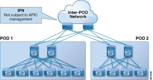
As illustrated in this figure, traffic between pods in a Multi-Pod topology passes through an IPN, which may contain devices that are not under Cisco APIC's management. When a network packet is sent from a spine or a leaf switch in POD1, the devices in the IPN may modify the 802.1p value in the packet. In this case, when the frame reaches a spine or a leaf switch in POD2, it would have an 802.1p value that was assigned by the IPN device, instead of the Cisco ACI QoS Level value assigned at the source in POD1.
In order to preserve the proper QoS Level of the packet and avoid high priority packets from being delayed or dropped, you can use a DSCP translation policy for traffic that goes between multiple PODs connected by an IPN. When a DSCP translation policy is enabled, Cisco APIC converts the QoS Level value (represented by the CoS value of the VXLAN packet) to a DSCP value according to the mapping rules you specify. When a packet sent from POD1 reaches POD2, the mapped DSCP value is translated back into the original CoS value for the appropriate QoS Level.
DSCP Translation Guidelines
-
Prior to Cisco APIC release 4.0(1), custom DSCP values could be assigned to User Levels 1 through 3.
-
Starting with Cisco APIC release 4.0(1), values can be selected for Levels 4 through 6 as well.
-
Starting with Cisco APIC release 4.0(1), if a multipod DSCP translation policy is enabled and the fabric hardware includes spine switch models that are earlier than the -EX switches, the CoS value for the traceroute policy must not overlap with the user traffic.
-
In addition to the values you configure in the DSCP translation policy, DSCP values
57-63are used by the ACI Control Plane traffic across IPN.
Note |
For traffic passing through the IPN, do not map any DSCP values to CS6. |
The following table provides definitions for the DSCP and ToS settings used in DSCP policies and maps:
|
DSCP or ToS Level |
Description |
|---|---|
|
AF11 |
Assured Forwarding Class 1, low probability of dropping |
|
AF12 |
Assured Forwarding Class 1, medium probability of dropping |
|
AF13 |
Assured Forwarding Class 1, high probability of dropping |
|
AF21 |
Assured Forwarding Class 2, low probability of dropping |
|
AF22 |
Assured Forwarding Class 2, medium probability of dropping |
|
AF23 |
Assured Forwarding Class 2, high probability of dropping |
|
AF31 |
Assured Forwarding Class 3, low probability of dropping |
|
AF32 |
Assured Forwarding Class 3, medium probability of dropping |
|
AF33 |
Assured Forwarding Class 3, high probability of dropping |
|
AF41 |
Assured Forwarding Class 4, low probability of dropping |
|
AF42 |
Assured Forwarding Class 4, medium probability of dropping |
|
AF43 |
Assured Forwarding Class 4, high probability of dropping |
|
CS0 |
TOS Class Selector value 0 (the default) |
|
CS1 |
TOS Class Selector value 1 (typically used for streaming traffic) |
|
CS2 |
TOS Class Selector value 2 (typically used for OAM traffic such as SNMP, SSH, and Syslog) |
|
CS3 |
TOS Class Selector value 3 (typically used for signalling traffic) |
|
CS4 |
TOS Class Selector value 4 (typically used for Policy Plane traffic and to priority queue) |
|
CS5 |
TOS Class Selector value 5 (typically used for broadcast video traffic) |
|
CS6 |
TOS Class Selector value 6 (typically used for Network control traffic) |
|
CS7 |
TOS Class Selector value 7 |
|
Expedited Forwarding |
EF is dedicated to low-loss, low-latency traffic |
|
Voice Admit |
Similar to EF, but also admitted through CAC |
Creating DSCP Translation Policy Using Cisco APIC GUI
This section describes how to create a DSCP translation policy to guarantee QoS Level settings across multiple PODs connected by an IPN.
Procedure
|
Step 1 |
Navigate to . |
||
|
Step 2 |
In the Navigation pane, expand . |
||
|
Step 3 |
In the Properties panel, click Enabled to enable the DSCP policy. |
||
|
Step 4 |
Check the No-Drop DSCP match control: enable nodrop dscp match checkbox to enable DSCP match for no-drop traffic for PFC classification on all spines including IPN interfaces. |
||
|
Step 5 |
Map each traffic stream to one of the available levels.
|
||
|
Step 6 |
Click Submit to save the changes. |
Creating DSCP Translation Policy Using NX-OS Style CLI
This section describes how to create a DSCP translation policy to guarantee QoS Level settings across multiple PODs connected by an IPN.
Procedure
|
Step 1 |
Enters configuration mode. |
||
|
Step 2 |
Enters tenant configuration mode for the |
||
|
Step 3 |
Create the DSCP translation map. |
||
|
Step 4 |
Configure the DSCP translation mappings.
|
||
|
Step 5 |
Enable the DSCP translation. |
Creating DSCP Translation Policy Using REST API
This section describes how to create a DSCP translation policy to guarantee QoS Level settings across multiple PODs connected by an IPN.
Procedure
|
Step 1 |
Enable and configure a DSCP translation policy. POST
https://<apic-ip>/api/node/mo/uni/tn-infra/dscptranspol-default.xml |
|
Step 2 |
Disable the DSCP translation policy. POST
https://<apic-ip>/api/node/mo/uni/tn-infra/dscptranspol-default.xml |
Configuring QoS On IPN Devices
This section describes how to configure QoS on the IPN devices to map traffic to the different classes specified as part of the DSCP translation policy described in the previous section.
Before you begin
You must have configured Multipod.
Procedure
|
Step 1 |
On the APIC, match the QoS Class Policy-Level 1, QoS Class Policy-Level 2, and QoS Class Policy-Level 3 according to the policy determined in the IP network (IPN to IPN).
|
|
Step 2 |
On the APIC, create a DSCP policy to enable guaranteeing QoS priority settings in a multipod topology and configure DSCP mappings for various traffic streams in the fabric. |
|
Step 3 |
On each IPN device, configure the following: |
|
Step 4 |
(Optional) Verify the ingress interface on IPN. You can verify the ingress interface settings as described in Verifying IPN Ingress Interface Settings. |
|
Step 5 |
(Optional) Verify the egress interface on IPN. You can verify the egress interface settings as described in Verifying IPN Egress Interface Settings. |
L3Outs QoS
L3Out QoS can be configured using Contracts applied at the external EPG level. Starting with Release 4.0(1), L3Out QoS can also be configured directly on the L3Out interfaces.
Note |
If you are running Cisco APIC Release 4.0(1) or later, we recommend using the custom QoS policies applied directly to the L3Out to configure QoS for L3Outs. |
Packets are classified using the ingress DSCP or CoS value so it is possible to use custom QoS policies to classify the incoming traffic into Cisco ACI QoS queues. A custom QoS policy contains a table mapping the DSCP/CoS values to the user queue and to the new DSCP/CoS value (in case of marking). If there is no mapping for a specific DSCP/CoS value, the user queue is selected by the QoS priority setting of the ingress L3Out interface if configured.
L3Outs QoS Guidelines and Limitations
The following guidelines and limitations apply to configuring QoS for L3Outs:
-
A custom QoS policy is not supported for Layer 3 multicast traffic sourced from outside the Cisco Application Centric Infrastructure (ACI) fabric (received from L3Out).
-
When configuring the QoS policy by using contracts to be enforced on the border leaf switch where the L3Out is located, the VRF table must be in egress mode (Policy Control Enforcement Direction must be "Egress").
A custom QoS setting can be configured directly on an L3Out and applied for the traffic coming from the border leaf switch, as such, the VRF table does not need to be in egress mode.
-
To enable the QoS policy to be enforced, the VRF Policy Control Enforcement Preference must be "Enforced."
-
When configuring the contract that controls communication between the L3Out and other EPGs, include the QoS class or target DSCP in the contract or subject.
Note
Only configure a QoS class or target DSCP in the contract, not in the external EPG (
l3extInstP).
-
When creating a contract subject, you must choose a QoS priority level. You cannot choose Unspecified.
Note
The exception is with custom QoS policies, as a custom QoS policy will set the DSCP/CoS value even if the QoS class is set to Unspecified. When the QoS level is unspecified, the level is treated as 3 by default.
-
On generation 2 switches, QoS supports levels 4, 5, and 6 configured under Global policies, EPG, L3Out, custom QoS, and Contracts. The following limitations apply:
-
The number of classes that can be configured with the strict priority is increased to 5.
-
The 3 new classes are supported only with generation 2 switches.
-
If traffic flows between generation 1 switches and generation 2 switches, the traffic will use QoS level 3.
-
For communicating with FEX for new classes, the traffic carries a Layer 2 CoS value of 0.
Generation 1 switches can be identified by the lack of "EX," "FX, "FX2," "GX," or later suffix at the end of the name. For example, N9K-9312TX. Generation 2 and later switches can be identified by the "EX," "FX, "FX2," "GX," or later suffix at the end of the name. For example N9K-93108TC-EX or N9K-9348GC-FXP.
-
-
You can configure QoS class or create a custom QoS policy to apply on an L3Out interface.
Configuring QoS Directly on L3Out Using GUI
This section describes how to configure QoS directly on an L3Out. This is the preferred way of configuring L3Out QoS starting with Cisco APIC Release 4.0(1).
Procedure
|
Step 1 |
From the main menu bar, select . |
|
Step 2 |
In the left-hand navigation pane, expand . You may need to create new network, node profile, and interface profile if none exists. |
|
Step 3 |
In the main window pane, configure custom QoS for your L3Out. You can choose to configure a standard QoS level priority using the QoS Priority drop-down list. Alternatively, you can set an existing or create a new custom QoS policy from the Custom QoS Policy dropdown. |
Configuring QoS Directly on L3Out Using CLI
This section describes how to configure QoS directly on an L3Out. This is the preferred way of configuring L3Out QoS starting with Cisco APIC Release 4.0(1).
You can configure QoS for L3Out on one of the following objects:
-
Switch Virtual Interface (SVI)
-
Sub Interface
-
Routed Outside
Procedure
|
Step 1 |
Configure QoS priorities for a L3Out SVI. Example: |
|
Step 2 |
Configure QoS priorities for a sub-interface. Example: |
|
Step 3 |
Configure QoS priorities for a routed outside. Example: |
Configuring QoS Directly on L3Out Using REST API
This section describes how to configure QoS directly on an L3Out. This is the preferred way of configuring L3Out QoS starting with Cisco APIC Release 4.0(1).
You can configure QoS for L3Out on one of the following objects:
-
Switch Virtual Interface (SVI)
-
Sub Interface
-
Routed Outside
Procedure
|
Step 1 |
Configure QoS priorities for a L3Out SVI. Example: |
|
Step 2 |
Configure QoS priorities for a sub-interface. Example: |
|
Step 3 |
Configure QoS priorities for a routed outside. Example: |
Configuring QoS Contracts for L3Outs Using GUI
This section describes how to configure QoS for L3Outs using Contracts.
Note |
Starting with Release 4.0(1), we recommend using custom QoS policies for L3Out QoS as described in Configuring QoS Directly on L3Out Using GUI instead. Configuring QoS classification using a contract as described in this section will take priority over any QoS policies configured directly on the L3Out. |
Procedure
|
Step 1 |
Configure the VRF instance for the tenant consuming the L3Out to support QoS to be enforced on the border leaf switch that is used by the L3Out. |
|
Step 2 |
When configuring filters for contracts to enable communication between the EPGs consuming the L3Out, include a QoS class or target DSCP to enforce the QoS priority in traffic ingressing through the L3Out.
|
|
Step 3 |
Add a contract. |
Configuring QoS Contract for L3Out Using CLI
This section describes how to configure QoS for L3Outs using Contracts.
Note |
Starting with Release 4.0(1), we recommend using custom QoS policies for L3Out QoS as described in Configuring QoS Directly on L3Out Using CLI instead. |
Procedure
|
Step 1 |
Configure the VRF for egress mode and enable policy enforcement to support QoS priority enforcement on the L3Out. |
||
|
Step 2 |
Configure QoS. When creating filters (
access-list), include the match dscp command with target DSCP level.
When configuring contracts, include the QoS class for traffic ingressing on the L3Out. Alternatively, you can define a target
DSCP value. QoS policies are supported on either the contract or the subject
VRF enforcement must be ingress, for QoS or custom QoS on L3out interface, VRF enforcement need be egress, only when the QOS classification is going to be done in the contract for traffic between EPG and L3out or L3out to L3out.
|
Configuring QoS Contract for L3Out Using REST API
This section describes how to configure QoS for L3Outs using Contracts.
Note |
Starting with Release 4.0(1), we recommend using custom QoS policies for L3Out QoS as described in Configuring QoS Directly on L3Out Using REST API instead. |
Procedure
|
Step 1 |
When configuring the tenant, VRF, and bridge domain, configure the VRF for egress mode ( Example: |
||||
|
Step 2 |
When creating the filters and contracts to enable the EPGs participating in the L3Out to communicate, configure the QoS priority. The contract in this example includes the QoS priority, The filter also has the
Example: |
SR-MPLS QoS
Starting with Release 5.0(1), Cisco ACI fabric supports QoS classification and marking for MPLS Segment Routing (SR-MPLS) traffic ingressing and egressing the fabric.
You can use custom QoS policies to define how traffic coming from an MPLS network is prioritized within ACI fabric. You can also use these policies to re-mark the traffic when it leaves the fabric via an MPLS L3Out.
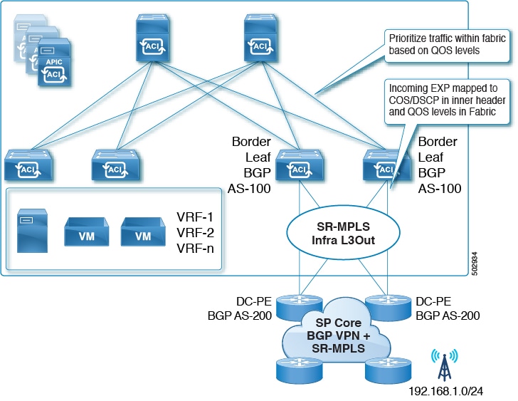
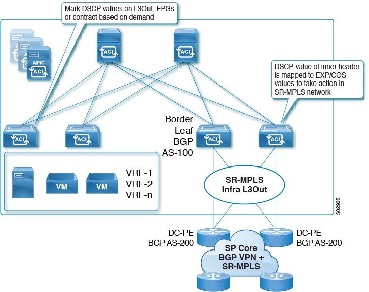
When configuring a custom QoS policy, you define the following two rules that are applied on the border leaf switch:
-
Ingress rules: These rules are applied for traffic that is ingressing the ACI fabric from an MPLS network and are used to map incoming packet's experimental bits (EXP) values to ACI QoS levels, as well as to set differentiated services code point (DSCP) values in the VXLAN header for the packet while it's inside the ACI fabric.
The values are derived at the border leaf using a custom QoS translation policy. The original DSCP values for traffic coming from SR-MPLS without any remarking. If a custom policy is not defined or not matched, default QoS Level (
Level3) is assigned. -
Egress rules: These rules are applied for the traffic that is leaving the ACI fabric via an MPLS L3Out and are used to map the packet's IPv4 DSCP value to the MPLS packet's EXP value as well as the internal ethernet frame's CoS value.
Classification is done at the non-border leaf switch based on existing policies used for EPG and L3Out traffic. If a custom policy is not defined or not matched, the default EXP value of
0is marked on all labels. EXP values are marked in both, default and custom policy scenarios, and are done on all MPLS labels in the packet.Custom MPLS egress policy can override existing EPG, L3out, and Contract QoS policies.
The following two figures summarize when the ingress and egress rules are applied as well as how the internal ACI traffic may remark the packets' QoS fields while inside the fabric.
SR-MPLS QoS Guidelines and Limitations
The following guidelines apply when configuring QoS policies for SR-MPLS traffic:
-
Matching Exp value in Contract-level custom QoS policy is not supported. Any custom QoS policy configured at the Contract level will override the global MPLS QoS policy.
-
Dynamic Packet Prioritization (DPP) is supported for both, ingress and egress traffic.
-
An MPLS interface can act as a SPAN source, but it cannot be configured as a monitor port.
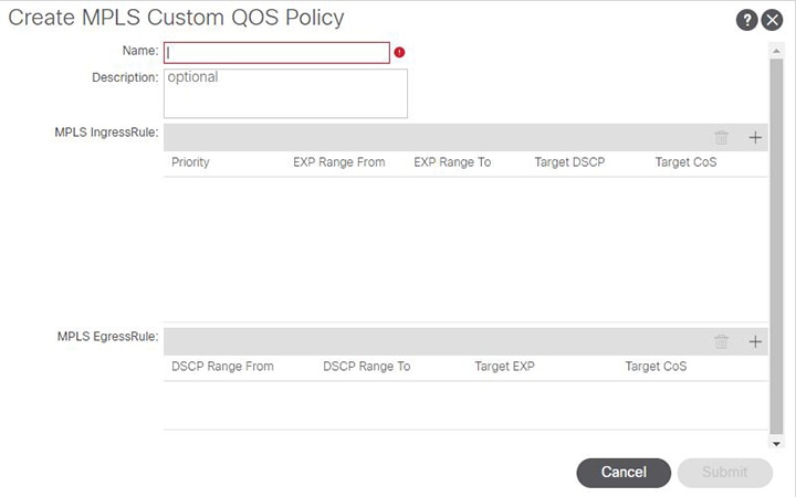
Creating SR-MPLS Custom QoS Policy Using the GUI
SR-MPLS Custom QoS policy defines the priority of the packets coming from an SR-MPLS network while they are inside the ACI fabric based on the incoming MPLS EXP values defined in the MPLS QoS ingress policy. It also marks the CoS and MPLS EXP values of the packets leaving the ACI fabric through an MPLS interface based on IPv4 DSCP values defined in MPLS QoS egress policy.
If no custom ingress policy is defined, the default QoS Level (Level3) is assigned to packets inside the fabric. If no custom egress policy is defined, the default EXP value of 0 will be marked on packets leaving the fabric.
Procedure
|
Step 1 |
From the top menu bar, navigate to . |
|
Step 2 |
In the left pane, select . |
|
Step 3 |
Right click the MPLS Custom QoS folder and choose Create MPLS Custom QoS Policy. |
|
Step 4 |
In the Create MPLS Custom QoS Policy window that opens, provide the name and description of the policy you're creating.
|
|
Step 5 |
In the MPLS Ingress Rule area, click + to add an ingress QoS translation rule. Any traffic coming into the border leaf (BL) connected to the MPLS network will be checked for the MPLS EXP value and if a match is found, the traffic is classified into an ACI QoS Level and marked with appropriate CoS and DSCP values.
|
|
Step 6 |
In the MPLS Egress Rule area, click + to add an egress QoS translation rule. When the traffic is leaving the fabric out of the border leaf's MPLS interface, it will be matched based on the DSCP value of the packet and if a match is found, the MPLS EXP and CoS values will be set based on the policy.
|
|
Step 7 |
Click OK to complete the creation of the MPLS custom QoS Policy. |
Creating SR-MPLS Custom QoS Policy Using CLI
SR-MPLS Custom QoS policy defines the priority of the packets coming from an SR-MPLS network while they are inside the ACI fabric based on the incoming MPLS EXP values defined in the MPLS QoS ingress policy. It also marks the CoS and MPLS EXP values of the packets leaving the ACI fabric through an MPLS interface based on IPv4 DSCP values defined in MPLS QoS egress policy.
If no custom ingress policy is defined, the default QoS Level (Level3) is assigned to packets inside the fabric. If no custom egress policy is defined, the default EXP value of 0 will be marked on packets leaving the fabric.
Procedure
|
Step 1 |
Create SR-MPLS QoS policy. |
|
Step 2 |
Apply SR-MPLS QoS policy. In the following commands:
|
Creating SR-MPLS Custom QoS Policy Using REST API
SR-MPLS Custom QoS policy defines the priority of the packets coming from an SR-MPLS network while they are inside the ACI fabric based on the incoming MPLS EXP values defined in the MPLS QoS ingress policy. It also marks the CoS and MPLS EXP values of the packets leaving the ACI fabric through an MPLS interface based on IPv4 DSCP values defined in MPLS QoS egress policy.
If no custom ingress policy is defined, the default QoS Level (Level3) is assigned to packets inside the fabric. If no custom egress policy is defined, the default EXP value of 0 will be marked on packets leaving the fabric.
Procedure
|
Step 1 |
Create SR-MPLS QoS policy. In the following POST:
|
|
Step 2 |
Applying SR-MPLS QoS policy. In the following POST, replace customqos1 with the name of the SR-MPLS QoS policy you created in the previous step. |
RoCEv2 and the Required APIC QoS Settings
Remote Direct Memory Access (RDMA) over Converged Ethernet (RoCE) technology allows data to be transferred between servers or from storage to server without having to pass through the CPU and main memory path of TCP/IP. The network adapters transfers data directly to and from the application memory bypassing the operating system and the CPU. This zero copy and CPU offloading approach ensures greater CPU availability for other tasks while providing low latency and reduced jitter. You can use a single fabric for both storage and compute. RoCEv2 provides more functionality by allowing RDMA to be used with both Layer 2 and Layer 3 (UDP/IP) packets, enabling Layer 3 routing over multiple subnets.
Starting with Cisco Application Policy Infrastructure Controller (APIC) release 4.0(1), you can enable RoCEv2 functionality in your fabric by configuring specific QoS options for Layer 3 traffic in Cisco APIC, such as Weighted Random Early Detection (WRED) congestion algorithm and Explicit Congestion Notification (ECN).
The following sections describe how to configure the required QoS options using three different methods: the Cisco APIC GUI, the NX-OS style CLI, and the REST API. Regardless of which method you choose, you must configure the following:
-
Weighted Random Early Detection (WRED) congestion algorithm, which manages congestion on spine switches using the following configuration options:
-
WRED Min Threshold: If the average queue size is below the minimum threshold value, the arriving packets are queued immediately.
-
WRED Max Threshold: If the average queue size is greater than the maximum threshold value, the arriving packets are dropped.
-
WRED Probability: If the average queue size is between the Min and Max threshold, the Probability value determines whether the packet is dropped or queued.
-
WRED Weight: Weight has a range of
0to7and is used to calculate average queue length. Lower weight prioritizes current queue length, while higher weight prioritizes older queue lengths.
-
-
Explicit Congestion Notification (ECN), which is used for congestion notification. If there is congestion, ECN gets the transmitting device to the reduce transmission rate until the congestion clears, allowing traffic to continue without pause. ECN along with WRED enables end-to-end congestion notification between two endpoints on the network.
-
Priority flow control (PFC), which is used to achieve Layer 2 flow control. PFC provides the capability to pause traffic if there is congestion.
Starting with release 5.2(5), you can use RoCEv2 together with Cisco ACI Multi-Pod, but the following guidelines and restrictions apply:
-
Remote leaf switches do not support RoCEv2 with Cisco ACI Multi-Pod.
-
Enable PFC end-to-end through an Inter-Pod Network (IPN).
-
Make sure that the class of service (CoS) is preserved over the IPNs between the spine switches of the different pods.
-
RoCEv2 supports only Cisco ACI QoS Level 1 or 2 inside the fabric.
-
Configure the IPN with regular PFC and WRED or ECN.
-
Enable Cisco ACI Multi-Pod QoS.
ROCEv2 Hardware Support
The following Cisco hardware is supported for ROCEv2 in this release:
-
Cisco Nexus 9300-EX platform switches
-
Cisco Nexus 9300-FX platform switches
-
Cisco Nexus 9300-FX2 platform switches
-
Cisco Nexus 9300-FX3 platform switches
-
Cisco Nexus 9300-GX platform switches
-
N9K-X9700-EX line cards
-
N9K-C9504-FM-E fabric modules
Configuring Priority Flow Control (PFC) On Interfaces
Before you can configure the appropriate QoS settings for ROCEv2, you must enable PFC on each interface that is connected
to ROCE devices. PFC setting can be set to one of three values, on, off, and auto. If you set it to auto, the DCBX protocol negotiates the PFC state on the interface.
You can configure PFC on one or more interfaces using any of the following methods:
-
Using the Cisco APIC GUI, as described in Configuring PFC On Interfaces Using GUI
-
Using the NX-OS style CLI, as described in Configuring PFC On Interfaces Using CLI
-
Using the REST API, as described in Configuring PFC On Interfaces Using REST API
Configuring PFC On Interfaces Using GUI
You can use the Cisco APIC GUI to configure PFC state on the interfaces connecting to ROCEv2 devices.
Procedure
|
Step 1 |
Log in to Cisco APIC. |
|
Step 2 |
From the top navigation bar, choose . |
|
Step 3 |
In the left-hand sidebar, navigate to . |
|
Step 4 |
In the main pane, select the Interface tab. |
|
Step 5 |
In the main pane, from the Mode dropdown menu, select Configuration. |
|
Step 6 |
Choose an L2 port you want to configure. |
|
Step 7 |
In the bottom pane, select the FCoE/FC tab. |
|
Step 8 |
Set the PFC State of the port to |
Configuring PFC On Interfaces Using CLI
You can use the NX-OS style CLI to configure PFC state on the interfaces connecting to ROCEv2 devices.
Procedure
|
Step 1 |
Enter APIC configuration mode. |
|
Step 2 |
Enter switch configuration. |
|
Step 3 |
Enable PFC for specific interfaces. |
Configuring PFC On Interfaces Using REST API
You can use REST API to configure PFC state on the interfaces connecting to ROCEv2 devices.
Procedure
|
Step 1 |
You can configure PFC state on a group of interfaces using a policy group. |
|
Step 2 |
Alternatively, you can configure PFC state on individual interfaces. |
Configuring QoS for ROCEv2
After you have enabled PFC on each interfaces that is connected to ROCE devices, you can configure the appropriate QoS settings for ROCEv2.
You can configure QoS for ROCE using any of the following methods:
-
Using the Cisco APIC GUI, as described in Configuring QoS for ROCEv2 Using the GUI
-
Using the NX-OS style CLI, as described in Configuring QoS for RoCEv2 Using CLI
-
Using the REST API, as described in Configuring QoS for RoCEv2 Using REST API
Configuring QoS for ROCEv2 Using the GUI
You can use the Cisco APIC GUI to configure the required QoS options to enable support for RoCEv2 in your fabric.
Procedure
|
Step 1 |
Log in to Cisco APIC. |
|
Step 2 |
Navigate to |
|
Step 3 |
Select the QOS Class Level for which you want to configure ROCEv2 |
|
Step 4 |
For the Congestion Algorithm option, select Weighted random early detection. |
|
Step 5 |
For the Congestion Notification option, select Enabled. Enabling Congestion Notification causes the packets that would be dropped to be ECN-marked instead. |
|
Step 6 |
For the Min Threshold (percentage) option, set the minimum queue threshold as a percentage of the maximum queue length. If the average queue size is below the minimum threshold value, the arriving packets are queued immediately. |
|
Step 7 |
For the Max Threshold (percentage) option, set the maximum queue threshold as a percentage of the maximum queue length. If the average queue size is greater than the maximum threshold value, the arriving packets are dropped or marked if ECN is enabled. |
|
Step 8 |
For the Probability (percentage) option, set the probability value. The probability determines whether the packet is dropped or queued when the average queue size is between the minimum and the maximum threshold values. |
|
Step 9 |
For the Weight option, set the weight value. Weight has a range of |
|
Step 10 |
Check the PFC Admin State checkbox and specify a value for the No-Drop-CoS option to be used by PFC. |
|
Step 11 |
For the Scope option, select |
|
Step 12 |
Optionally, you can choose to enable the Forward Non-ECN Traffic option, so that non-ECN traffic is not dropped even when the queue is congested. Congestion Notification must be enabled for this option to be configurable. |
Configuring QoS for RoCEv2 Using CLI
You can use the NX-OS style CLI to configure the required QoS options to enable support for RoCEv2 in your fabric.
Procedure
|
Step 1 |
Enter configuration mode. |
|
Step 2 |
Choose the QoS Level you want to configure. In the following command, replace level2 with the QoS Level you want to configure: |
|
Step 3 |
Configure the congestion algorithm and its parameters. |
|
Step 4 |
(Optional) Configure forwarding of the non-ECN traffic. You can choose to enable forwarding of all non-ECN traffic, even when the queue is congested. |
|
Step 5 |
Exit congestion algorithm configuration. |
|
Step 6 |
Configure the CoS value for the QoS Level you chose. If you do not provide the |
Configuring QoS for RoCEv2 Using REST API
You can use REST API to configure the required QoS options to enable support for RoCEv2 in your fabric.
Procedure
|
Step 1 |
Configure QoS for RoCEv2. In the following example, replace level2 with the QoS class you want to configure and the WRED parameters with values appropriate for your environment.
|
|
Step 2 |
(Optional) Configure forwarding of the non-ECN traffic. You can choose to enable forwarding of all non-ECN traffic, even when the queue is congested. |
Troubleshooting Cisco APIC QoS Policies
The following sections summarize common troubleshooting scenarios for Cisco APIC QoS.
Unable to Update a Configured QoS Policy
-
Invoke the following API to ensure that
qospDscpRuleis present on the leaf.GET https://192.0.20.123/api/node/class/qospDscpRule.xml -
Ensure that the QoS rules are accurately configured and associated to the EPG ID to which the policy is attached.
Use the following NX-OS style CLI commands to verify the configuration.
leaf1# show vlan
leaf1# show system internal aclqos qos policy detail

apic1# show running-config tenant tenant-name policy-map type qos custom-qos-policy-name
apic1# show running-config tenant tenant-name application application-name epg epg-name
Show QoS Interface Statistics by Using the CLI
CLI displays statistics for eth1/1 for only QoS classes – level1, leve2, level3, level4, level5, level6, and policy-plane – if you don’t use the "detail" option.
NXOS ibash cli: tor-leaf1# show queuing interface ethernet 1/1 [detail]If you want to display statistics for control-plane and span classes for an interface, you need to use CLI with the "detail" option.
Example: fabric 107 show queuing interface ethernet 1/1 detail
APIC CLI:
swtb123-ifc1# fabric node_id show queuing interface ethernet 1/1 swtb95-leaf1# show queuing interface ethernet 1/31
====================================
Queuing stats for ethernet 1/31
====================================
Qos Class level3
====================================
Rx Admit Pkts : 0 Tx Admit Pkts : 0
Rx Admit Bytes: 0 Tx Admit Bytes: 0
Rx Drop Pkts : 0 Tx Drop Pkts : 0
Rx Drop Bytes : 0 Tx Drop Bytes : 0
====================================
Qos Class level2
====================================
Rx Admit Pkts : 0 Tx Admit Pkts : 0
Rx Admit Bytes: 0 Tx Admit Bytes: 0
Rx Drop Pkts : 0 Tx Drop Pkts : 0
Rx Drop Bytes : 0 Tx Drop Bytes : 0
====================================
Qos Class level1
====================================
Rx Admit Pkts : 0 Tx Admit Pkts : 0
Rx Admit Bytes: 0 Tx Admit Bytes: 0
Rx Drop Pkts : 0 Tx Drop Pkts : 0
Rx Drop Bytes : 0 Tx Drop Bytes : 0
====================================
Qos Class level6
====================================
Rx Admit Pkts : 0 Tx Admit Pkts : 401309848
Rx Admit Bytes: 0 Tx Admit Bytes: 47354562064
Rx Drop Pkts : 0 Tx Drop Pkts : 2066740320
Rx Drop Bytes : 0 Tx Drop Bytes : 140538341760 Show QoS Interface Statistics by Using the APIC GUI
Use the APIC GUI to view the QoS statistics.
Navigate to Fabric->Inventory>Pod Number > Node Hostname > Physical Interfaces > Interface-> QoS Stats to view the the QoS stats as shown below:
Verifying IPN Ingress Interface Settings
This section describes how to verify the IPN ingress interface settings you have configured in Configuring QoS On IPN Devices.
IPNPOD2# show policy-map interface ethernet 1/50.4 input

Global statistics status :   enabled

Ethernet1/50.4

  Service-policy (qos) input:   ACI-CLASSIFICATION
    SNMP Policy Index:  285215377

    Class-map (qos):   CONTROL-TRAFFIC (match-all)

     Slot 1
        1434 packets
     Aggregate forwarded :
        1434 packets
      Match: dscp 48,56
      set qos-group 7

    Class-map (qos):   UserLevel1 (match-all)
     Aggregate forwarded :
        0 packets
      Match: dscp 46
      set qos-group 6

    Class-map (qos):   UserLevel2 (match-all)
     Aggregate forwarded :
        0 packets
      Match: dscp 24
      set qos-group 3

    Class-map (qos):   UserLevel3 (match-all)

     Slot 1
        25 packets
     Aggregate forwarded :
        25 packets
      Match: dscp 0
      set qos-group 0

    Class-map (qos):   SpanTraffic (match-all)
     Aggregate forwarded :
        0 packets
      Match: dscp 8
      set qos-group 1

    Class-map (qos):   iTraceroute (match-all)
     Aggregate forwarded :
        0 packets
      Match: dscp 40
      set qos-group 5


IPNPOD2# show policy-map interface ethernet 1/49.4 input
Global statistics status :   enabled

Ethernet1/49.4

  Global statistics status :   enabled

Ethernet1/49.4

  Service-policy (qos) input:   ACI-CLASSIFICATION
    SNMP Policy Index:  285215373

    Class-map (qos):   CONTROL-TRAFFIC (match-all)

     Slot 1
        5149 packets
     Aggregate forwarded :
        5149 packets
      Match: dscp 48,56
      set qos-group 7

    Class-map (qos):   UserLevel1 (match-all)
     Aggregate forwarded :
        0 packets
      Match: dscp 46
      set qos-group 6

    Class-map (qos):   UserLevel2 (match-all)
     Aggregate forwarded :
        0 packets
      Match: dscp 24
      set qos-group 3

    Class-map (qos):   UserLevel3 (match-all)

     Slot 1
        960 packets
     Aggregate forwarded :
        960 packets
      Match: dscp 0
      set qos-group 0

    Class-map (qos):   SpanTraffic (match-all)
     Aggregate forwarded :
        0 packets
      Match: dscp 8
      set qos-group 1

    Class-map (qos):   iTraceroute (match-all)
     Aggregate forwarded :
        0 packets
      Match: dscp 40
      set qos-group 5
Verifying IPN Egress Interface Settings
This section describes how to verify the IPN egress interface settings you have configured in Configuring QoS On IPN Devices.
IPNPOD1# show queuing interface e 1/3 | b "GROUP 7"
slot 1
=======
Egress Queuing for Ethernet1/3 [System]
------------------------------------------------------------------------------
QoS-Group# Bandwidth% PrioLevel Shape QLimit
Min Max Units
------------------------------------------------------------------------------
7 - 1 - - - 9(D)
6 - 2 - - - 9(D)
5 0 - - - - 9(D)
4 0 - - - - 9(D)
3 20 - - - - 9(D)
2 0 - - - - 9(D)
1 1 - - - - 9(D)
0 59 - - - - 9(D)
+-------------------------------------------------------------+
| QOS GROUP 0 |
+-------------------------------------------------------------+
| | Unicast |Multicast |
+-------------------------------------------------------------+
| Tx Pkts | 125631| 70|
| Tx Byts | 42902871| 8836|
| WRED/AFD & Tail Drop Pkts | 0| 0|
| WRED/AFD & Tail Drop Byts | 0| 0|
| Q Depth Byts | 0| 0|
| WD & Tail Drop Pkts | 0| 0|
+-------------------------------------------------------------+
| QOS GROUP 1 |
+-------------------------------------------------------------+
| | Unicast |Multicast |
+-------------------------------------------------------------+
| Tx Pkts | 0| 0|
| Tx Byts | 0| 0|
| WRED/AFD & Tail Drop Pkts | 0| 0|
| WRED/AFD & Tail Drop Byts | 0| 0|
| Q Depth Byts | 0| 0|
| WD & Tail Drop Pkts | 0| 0|
+-------------------------------------------------------------+
| QOS GROUP 2 |
+-------------------------------------------------------------+
| | Unicast |Multicast |
+-------------------------------------------------------------+
| Tx Pkts | 0| 0|
| Tx Byts | 0| 0|
| WRED/AFD & Tail Drop Pkts | 0| 0|
| WRED/AFD & Tail Drop Byts | 0| 0|
| Q Depth Byts | 0| 0|
| WD & Tail Drop Pkts | 0| 0|
+-------------------------------------------------------------+
| QOS GROUP 3 |
+-------------------------------------------------------------+
| | Unicast |Multicast |
+-------------------------------------------------------------+
| Tx Pkts | 0| 0|
| Tx Byts | 0| 0|
| WRED/AFD & Tail Drop Pkts | 0| 0|
| WRED/AFD & Tail Drop Byts | 0| 0|
| Q Depth Byts | 0| 0|
| WD & Tail Drop Pkts | 0| 0|
+-------------------------------------------------------------+
| QOS GROUP 4 |
+-------------------------------------------------------------+
| | Unicast |Multicast |
+-------------------------------------------------------------+
| Tx Pkts | 0| 0|
| Tx Byts | 0| 0|
| WRED/AFD & Tail Drop Pkts | 0| 0|
| WRED/AFD & Tail Drop Byts | 0| 0|
| Q Depth Byts | 0| 0|
| WD & Tail Drop Pkts | 0| 0|
+-------------------------------------------------------------+
| QOS GROUP 5 |
+-------------------------------------------------------------+
| | Unicast |Multicast |
+-------------------------------------------------------------+
| Tx Pkts | 0| 0|
| Tx Byts | 0| 0|
| WRED/AFD & Tail Drop Pkts | 0| 0|
| WRED/AFD & Tail Drop Byts | 0| 0|
| Q Depth Byts | 0| 0|
| WD & Tail Drop Pkts | 0| 0|
+-------------------------------------------------------------+
| QOS GROUP 6 |
+-------------------------------------------------------------+
| | Unicast |Multicast |
+-------------------------------------------------------------+
| Tx Pkts | 645609| 217|
| Tx Byts | 115551882| 25606|
| WRED/AFD & Tail Drop Pkts | 0| 0|
| WRED/AFD & Tail Drop Byts | 0| 0|
| Q Depth Byts | 0| 0|
| WD & Tail Drop Pkts | 0| 0|
+-------------------------------------------------------------+
| QOS GROUP 7 |
+-------------------------------------------------------------+
| | Unicast |Multicast |
+-------------------------------------------------------------+
| Tx Pkts | 23428| 9|
| Tx Byts | 4132411| 1062|
| WRED/AFD & Tail Drop Pkts | 0| 0|
| WRED/AFD & Tail Drop Byts | 0| 0|
| Q Depth Byts | 0| 0|
| WD & Tail Drop Pkts | 0| 0|
+-------------------------------------------------------------+
| CONTROL QOS GROUP |
+-------------------------------------------------------------+
| | Unicast |Multicast |
+-------------------------------------------------------------+
| Tx Pkts | 6311| 0|
| Tx Byts | 809755| 0|
| Tail Drop Pkts | 0| 0|
| Tail Drop Byts | 0| 0|
| WD & Tail Drop Pkts | 0| 0|
+-------------------------------------------------------------+
| SPAN QOS GROUP |
+-------------------------------------------------------------+
| | Unicast |Multicast |
+-------------------------------------------------------------+
| Tx Pkts | 0| 0|
| Tx Byts | 0| 0|
| Tail Drop Pkts | 0| 0|
| Tail Drop Byts | 0| 0|
| WD & Tail Drop Pkts | 0| 0|
+-------------------------------------------------------------+
Ingress Queuing for Ethernet1/3
-----------------------------------------------------
QoS-Group# Pause
Buff Size Pause Th Resume Th
-----------------------------------------------------
7 - - -
6 - - -
5 - - -
4 - - -
3 - - -
2 - - -
1 - - -
0 - - -
Per Port Ingress Statistics
--------------------------------------------------------
Hi Priority Drop Pkts 0
Low Priority Drop Pkts 0
Ingress Overflow Drop Pkts 0
PFC Statistics
------------------------------------------------------------------------------
TxPPP: 0, RxPPP: 0
------------------------------------------------------------------------------
PFC_COS QOS_Group TxPause TxCount RxPause RxCount
0 0 Inactive 0 Inactive 0
1 0 Inactive 0 Inactive 0
2 0 Inactive 0 Inactive 0
3 0 Inactive 0 Inactive 0
4 0 Inactive 0 Inactive 0
5 0 Inactive 0 Inactive 0
6 0 Inactive 0 Inactive 0
7 0 Inactive 0 Inactive 0
------------------------------------------------------------------------------
IPNPOD2# show queuing interface e 1/4
slot 1
=======
Egress Queuing for Ethernet1/4 [System]
------------------------------------------------------------------------------
QoS-Group# Bandwidth% PrioLevel Shape QLimit
Min Max Units
------------------------------------------------------------------------------
7 - 1 - - - 9(D)
6 - 2 - - - 9(D)
5 0 - - - - 9(D)
4 0 - - - - 9(D)
3 20 - - - - 9(D)
2 0 - - - - 9(D)
1 1 - - - - 9(D)
0 59 - - - - 9(D)
+-------------------------------------------------------------+
| QOS GROUP 0 |
+-------------------------------------------------------------+
| | Unicast |Multicast |
+-------------------------------------------------------------+
| Tx Pkts | 63049| 0|
| Tx Byts | 15968783| 0|
| WRED/AFD & Tail Drop Pkts | 0| 0|
| WRED/AFD & Tail Drop Byts | 0| 0|
| Q Depth Byts | 0| 0|
| WD & Tail Drop Pkts | 0| 0|
+-------------------------------------------------------------+
| QOS GROUP 1 |
+-------------------------------------------------------------+
| | Unicast |Multicast |
+-------------------------------------------------------------+
| Tx Pkts | 0| 0|
| Tx Byts | 0| 0|
| WRED/AFD & Tail Drop Pkts | 0| 0|
| WRED/AFD & Tail Drop Byts | 0| 0|
| Q Depth Byts | 0| 0|
| WD & Tail Drop Pkts | 0| 0|
+-------------------------------------------------------------+
| QOS GROUP 2 |
+-------------------------------------------------------------+
| | Unicast |Multicast |
+-------------------------------------------------------------+
| Tx Pkts | 0| 0|
| Tx Byts | 0| 0|
| WRED/AFD & Tail Drop Pkts | 0| 0|
| WRED/AFD & Tail Drop Byts | 0| 0|
| Q Depth Byts | 0| 0|
| WD & Tail Drop Pkts | 0| 0|
+-------------------------------------------------------------+
| QOS GROUP 3 |
+-------------------------------------------------------------+
| | Unicast |Multicast |
+-------------------------------------------------------------+
| Tx Pkts | 0| 0|
| Tx Byts | 0| 0|
| WRED/AFD & Tail Drop Pkts | 0| 0|
| WRED/AFD & Tail Drop Byts | 0| 0|
| Q Depth Byts | 0| 0|
| WD & Tail Drop Pkts | 0| 0|
+-------------------------------------------------------------+
| QOS GROUP 4 |
+-------------------------------------------------------------+
| | Unicast |Multicast |
+-------------------------------------------------------------+
| Tx Pkts | 0| 0|
| Tx Byts | 0| 0|
| WRED/AFD & Tail Drop Pkts | 0| 0|
| WRED/AFD & Tail Drop Byts | 0| 0|
| Q Depth Byts | 0| 0|
| WD & Tail Drop Pkts | 0| 0|
+-------------------------------------------------------------+
| QOS GROUP 5 |
+-------------------------------------------------------------+
| | Unicast |Multicast |
+-------------------------------------------------------------+
| Tx Pkts | 0| 0|
| Tx Byts | 0| 0|
| WRED/AFD & Tail Drop Pkts | 0| 0|
| WRED/AFD & Tail Drop Byts | 0| 0|
| Q Depth Byts | 0| 0|
| WD & Tail Drop Pkts | 0| 0|
+-------------------------------------------------------------+
| QOS GROUP 6 |
+-------------------------------------------------------------+
| | Unicast |Multicast |
+-------------------------------------------------------------+
| Tx Pkts | 1141418| 0|
| Tx Byts | 237770324| 0|
| WRED/AFD & Tail Drop Pkts | 0| 0|
| WRED/AFD & Tail Drop Byts | 0| 0|
| Q Depth Byts | 0| 0|
| WD & Tail Drop Pkts | 0| 0|
+-------------------------------------------------------------+
| QOS GROUP 7 |
+-------------------------------------------------------------+
| | Unicast |Multicast |
+-------------------------------------------------------------+
| Tx Pkts | 32440| 0|
| Tx Byts | 6986806| 0|
| WRED/AFD & Tail Drop Pkts | 0| 0|
| WRED/AFD & Tail Drop Byts | 0| 0|
| Q Depth Byts | 0| 0|
| WD & Tail Drop Pkts | 0| 0|
+-------------------------------------------------------------+
| CONTROL QOS GROUP |
+-------------------------------------------------------------+
| | Unicast |Multicast |
+-------------------------------------------------------------+
| Tx Pkts | 6275| 0|
| Tx Byts | 804748| 0|
| Tail Drop Pkts | 0| 0|
| Tail Drop Byts | 0| 0|
| WD & Tail Drop Pkts | 0| 0|
+-------------------------------------------------------------+
| SPAN QOS GROUP |
+-------------------------------------------------------------+
| | Unicast |Multicast |
+-------------------------------------------------------------+
| Tx Pkts | 0| 0|
| Tx Byts | 0| 0|
| Tail Drop Pkts | 0| 0|
| Tail Drop Byts | 0| 0|
| WD & Tail Drop Pkts | 0| 0|
+-------------------------------------------------------------+
Ingress Queuing for Ethernet1/4
-----------------------------------------------------
QoS-Group# Pause
Buff Size Pause Th Resume Th
-----------------------------------------------------
7 - - -
6 - - -
5 - - -
4 - - -
3 - - -
2 - - -
1 - - -
0 - - -
Per Port Ingress Statistics
--------------------------------------------------------
Hi Priority Drop Pkts 0
Low Priority Drop Pkts 0
Ingress Overflow Drop Pkts 0
PFC Statistics
------------------------------------------------------------------------------
TxPPP: 0, RxPPP: 0
------------------------------------------------------------------------------
PFC_COS QOS_Group TxPause TxCount RxPause RxCount
0 0 Inactive 0 Inactive 0
1 0 Inactive 0 Inactive 0
2 0 Inactive 0 Inactive 0
3 0 Inactive 0 Inactive 0
4 0 Inactive 0 Inactive 0
5 0 Inactive 0 Inactive 0
6 0 Inactive 0 Inactive 0
7 0 Inactive 0 Inactive 0
------------------------------------------------------------------------------
 Feedback