Design Guide to Run VMware NSX-T with Cisco ACI White Paper
Available Languages
Bias-Free Language
The documentation set for this product strives to use bias-free language. For the purposes of this documentation set, bias-free is defined as language that does not imply discrimination based on age, disability, gender, racial identity, ethnic identity, sexual orientation, socioeconomic status, and intersectionality. Exceptions may be present in the documentation due to language that is hardcoded in the user interfaces of the product software, language used based on RFP documentation, or language that is used by a referenced third-party product. Learn more about how Cisco is using Inclusive Language.
THE SPECIFICATIONS AND INFORMATION REGARDING THE PRODUCTS IN THIS MANUAL ARE SUBJECT TO CHANGE WITHOUT NOTICE. ALL STATEMENTS, INFORMATION, AND RECOMMENDATIONS IN THIS MANUAL ARE BELIEVED TO BE ACCURATE BUT ARE PRESENTED WITHOUT WARRANTY OF ANY KIND, EXPRESS OR IMPLIED. USERS MUST TAKE FULL RESPONSIBILITY FOR THEIR APPLICATION OF ANY PRODUCTS.
THE SOFTWARE LICENSE AND LIMITED WARRANTY FOR THE ACCOMPANYING PRODUCT ARE SET FORTH IN THE INFORMATION PACKET THAT SHIPPED WITH THE PRODUCT AND ARE INCORPORATED HEREIN BY THIS REFERENCE. IF YOU ARE UNABLE TO LOCATE THE SOFTWARE LICENSE OR LIMITED WARRANTY, CONTACT YOUR CISCO REPRESENTATIVE FOR A COPY.
The Cisco implementation of TCP header compression is an adaptation of a program developed by the University of California, Berkeley (UCB) as part of UCB's public domain version of the UNIX operating system. All rights reserved. Copyright © 1981, Regents of the University of California.
NOTWITHSTANDING ANY OTHER WARRANTY HEREIN, ALL DOCUMENT FILES AND SOFTWARE OF THESE SUPPLIERS ARE PROVIDED “AS IS" WITH ALL FAULTS. CISCO AND THE ABOVE-NAMED SUPPLIERS DISCLAIM ALL WARRANTIES, EXPRESSED OR IMPLIED, INCLUDING, WITHOUT LIMITATION, THOSE OF MERCHANTABILITY, FITNESS FOR A PARTICULAR PURPOSE AND NONINFRINGEMENT OR ARISING FROM A COURSE OF DEALING, USAGE, OR TRADE PRACTICE.
IN NO EVENT SHALL CISCO OR ITS SUPPLIERS BE LIABLE FOR ANY INDIRECT, SPECIAL, CONSEQUENTIAL, OR INCIDENTAL DAMAGES, INCLUDING, WITHOUT LIMITATION, LOST PROFITS OR LOSS OR DAMAGE TO DATA ARISING OUT OF THE USE OR INABILITY TO USE THIS MANUAL, EVEN IF CISCO OR ITS SUPPLIERS HAVE BEEN ADVISED OF THE POSSIBILITY OF SUCH DAMAGES.
Any Internet Protocol (IP) addresses and phone numbers used in this document are not intended to be actual addresses and phone numbers. Any examples, command display output, network topology diagrams, and other figures included in the document are shown for illustrative purposes only. Any use of actual IP addresses or phone numbers in illustrative content is unintentional and coincidental.
This product includes cryptographic software written by Eric Young (eay@cryptsoft.com).
This product includes software developed by the OpenSSL Project for use in the OpenSSL Toolkit. (http://www.openssl.org/)
This product includes software written by Tim Hudson (tjh@cryptsoft.com).
Cisco and the Cisco logo are trademarks or registered trademarks of Cisco and/or its affiliates in the U.S. and other countries. To view a list of Cisco trademarks, go to this URL: https://www.cisco.com/go/trademarks. Third-party trademarks mentioned are the property of their respective owners. The use of the word partner does not imply a partnership relationship between Cisco and any other company. (1110R)
With the launch of the Cisco Application Centric Infrastructure (Cisco ACI) solution in 2013, Cisco continued the trend of providing best-in-class solutions for VMware vSphere environments. Cisco ACI is a comprehensive Software-Defined Networking (SDN) architecture that delivers a better network, implementing distributed Layer 2 and Layer 3 services across multiple sites using integrated Virtual Extensible LAN (VXLAN) overlays. Cisco ACI also enables distributed security for any type of workload, and introduces policy-based automation with a single point of management. The core of the Cisco ACI solution, the Cisco Application Policy Infrastructure Controller (APIC), provides deep integration with multiple hypervisors, including VMware vSphere, Microsoft Hyper-V, and Red Hat Virtualization; and with modern cloud and container cluster management platforms, such as OpenStack, OpenShift, Rancher and Kubernetes. The APIC not only manages the entire physical fabric but also manages the native virtual switching offering for each of the hypervisors or container nodes.
Since its introduction, Cisco ACI has seen incredible market adoption and is currently deployed by thousands of customers across the globe, in all industry segments.
In parallel, some vSphere customers may choose to deploy hypervisor-centric SDN solutions, such as VMware NSX-T (sometimes also called NSX Data Center), oftentimes as a means of improving security in their virtualized environments. This leads customers to wonder how to best combine NSX-T and Cisco ACI. This document is intended to help those customers by explaining the design considerations and options for running VMware NSX-T with a Cisco ACI fabric.
This document explains the benefits of Cisco ACI as a foundation for VMware vSphere, as well as how it makes NSX-T easier to deploy, more cost effective, and simpler to troubleshoot when compared to running NSX-T on a traditional fabric design.
As Cisco ACI fabrics provide a unified overlay and underlay, two possible NSX-T deployments options are discussed (Figure 1):
● Option 1. Running NSX-T security and virtual services with a Cisco ACI integrated overlay: In this model, Cisco ACI provides overlay capability and distributed networking, while NSX-T is used for distributed firewalling, microsegmentation, and services such as load balancing.
● Option 2. Running NSX-T overlay as an application: In this deployment model, the NSX-T overlay is used to provide connectivity between vSphere virtual machines, and the Cisco APIC manages the underlying networking, as it does for vMotion, IP storage, or fault tolerance.
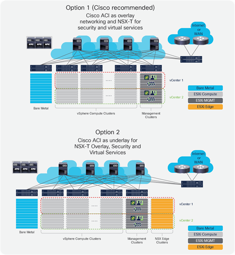
VMware NSX-T deployment options
These two deployment options are not mutually exclusive. While Cisco ACI offers substantial benefits in both of these scenarios when compared to a traditional device-by-device managed data center fabric, the first option is recommended, because it allows customers to avoid the complexities and performance challenges associated with deploying and operating NSX-T Edge Nodes for north-south traffic and eliminates the need to deploy any GENEVE (Generic Network Virtualization Encapsulation)-to-VLAN gateway functions.
Regardless of the option chosen, some key advantages of using Cisco ACI as a fabric for NSX-T workloads are significant, including:
● Best-in-class performance: Cisco ACI builds on best-in-class Cisco Nexus® 9000 Series Switches to implement a low-latency fabric that uses Cisco Cloud Scale smart buffering and provides the highest performance on a leaf-and-spine architecture.
● Simpler management: Cisco ACI offers a single point of management for the physical fabric with full FCAPS[1] capabilities, thus providing for a much simpler environment for running all required vSphere services with high levels of availability and visibility.
● Simplified NSX-T networking: Because of the programmable fabric capabilities of the Cisco ACI solution, customers can deploy NSX-T GENEVE tunnel endpoints (VTEPs) with minimal fabric configuration, as opposed to device-by-device subnet and VLAN configurations. In addition, customers can optimize, reduce, or completely eliminate the need for NSX-T Edge Nodes. This contributes to requiring fewer computing resources and simplifying the virtual topology.
● Operational benefits: The Cisco ACI policy-based model with single point of management facilitates setting up vSphere clusters while providing better visibility, enhanced security, and easier troubleshooting of connectivity within and between clusters. Furthermore, Cisco ACI provides many built-in network management functions, including consolidated logging with automatic event correlation, troubleshooting wizards, software lifecycle management, and capacity management.
● Lower total cost of ownership: Operational benefits provided by Cisco ACI and the savings in resources and licenses from enabling optimal placement of NSX-T Edge Nodes, along with faster time to recovery and easier capacity planning, add up to reduced costs overall.
This document is intended for network, security, and virtualization administrators who will deploy NSX-T on a Cisco ACI fabric. We anticipate that the reader is familiar with NSX-T and with Cisco ACI capabilities. Furthermore, general networking knowledge is assumed.
Cisco ACI is the industry’s most widely adopted SDN for data center networking. Cisco ACI pioneered the introduction of intent-based networking in the data center. It builds on a leaf-and-spine fabric architecture with an APIC that acts as the unifying point of policy and management.
The APIC implements a modern object model to provide a complete abstraction of every element in the fabric. This model includes all aspects of the physical devices, such as interfaces or forwarding tables, as well as its logical elements, like network protocols and all connected virtual or physical endpoints. The APIC extends the principles of Cisco UCS® Manager software and its service profiles to the entire network: everything in the fabric is represented in an object model at the APIC, enabling declarative, policy-based provisioning for all fabric functions and a single point of management for day 2 operations.
Networks are by nature distributed systems. This distributed characteristic has brought significant challenges when managing fabrics: if a network administrator wishes to modify a certain network attribute, touching discrete switches or routers is required. This necessity poses significant challenges when deploying new network constructs or troubleshooting network issues.
Cisco ACI fixes that problem by offloading the management plane of network devices to a centralized controller. This way, when provisioning, managing, and operating a network, the administrator only needs to access the APIC.
It is very important to note that in the Cisco ACI architecture, centralizing the management and policy planes in the APIC does not impose scalability bottlenecks in the network, as the APIC fabric management functions do not operate in the data plane of the fabric. Both the control plane (intelligence) and data plane (forwarding) functions are performed within the switching layer by intelligent Nexus 9000 Series Switches, which use a combination of software and hardware features.
A centralized management and policy plane also does not mean that the network is less reliable or has a single point of failure. As the intelligence function stays at the switches, the switches can react to any network failure without having to ask the controller what to do.
Because a highly available scale-out cluster of at least three APIC nodes is used, any controller outage does not diminish the capabilities of the network. In the unlikely event of a complete controller cluster outage, the fabric can still react to such events as the addition of new endpoints or the movement of existing endpoints across hypervisors (for instance, when performing virtual machine vMotion operations).
The Cisco ACI policy model provides a complete abstraction from the physical devices to allow programmable deployment of all network configurations. Everything can be programmed through a single, open API, whether it is physical interface settings, routing protocols, or application connectivity requirements inclusive of advanced network services.
The Cisco ACI fabric is a VXLAN-based leaf-and-spine architecture that provides Layer 2 and Layer 3 services with integrated overlay capabilities. Cisco ACI delivers integrated network virtualization for all workloads connected, and the APIC can manage not only physical devices but also virtual switches. Virtual and physical endpoints can connect to the fabric without any need for gateways or additional per-server software and licenses. The Cisco ACI solution works with all virtualized compute environments, providing tight integration with leading virtualization platforms like VMware vSphere, VMware NSX-T, Microsoft System Center VMM, or Red Hat Virtualization. APIC also integrates with the leading open-source cloud management solution, OpenStack, by having APIC program distributed services on Open vSwitch using OpFlex. Finally, the Cisco ACI declarative model for defining application connectivity also goes hand in hand with modern frameworks for running Linux containers, and Cisco ACI has the same level of integration with Kubernetes and OpenShift.
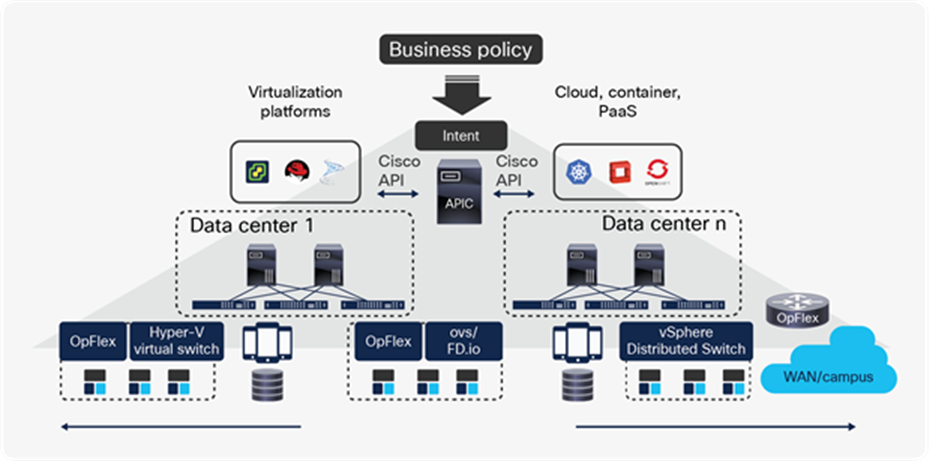
APIC declarative model enables intent-based networking
This configuration provides an enormous operational advantage because the APIC has visibility into all the attached endpoints and has automatic correlation between virtual and physical environments and their application or tenant context. Integration with virtualization solutions is implemented by defining virtual machine manager domains in APIC.
This document focuses on on-premises Cisco ACI data centers. For information about Cisco Cloud ACI, please refer to the following white papers:
● Cisco Cloud ACI on AWS White Paper
● Cisco Cloud ACI on Microsoft Azure White Paper
The Cisco ACI solution is built around a comprehensive policy model that manages the entire fabric, including the infrastructure, authentication, security, services, applications, and diagnostics. A set of logical constructs, such as Virtual Routing and Forwarding (VRF) tables, bridge domains, Endpoint Groups (EPGs), Endpoint Security Group (ESGs), and contracts, define the complete operation of the fabric, including connectivity, security, and management. This document primarily uses EPGs as groups of application endpoints, though ESGs can also be used for grouping application endpoints.
At the upper level of the Cisco ACI model, tenants are network-wide administrative folders. The Cisco ACI tenancy model can be used to isolate separate organizations, such as sales and engineering, or different environments such as development, test, and production, or combinations of both. It can also be used to isolate infrastructure for different technologies or fabric users, for instance, VMware infrastructure versus OpenStack versus big data, Mesos, and so forth. The use of tenants facilitates organizing and applying security policies to the network and providing automatic correlation of statistics, events, failures, and audit data.
Cisco ACI supports thousands of tenants that are available for users. One special tenant is the “common tenant,” which can be shared across all other tenants, as the name implies. Other tenants can consume any object that exists within the common tenant. Customers that choose to use a single tenant may configure everything under the common tenant, although in general it is best to create a dedicated user tenant and keep the common for shared resources.
Cisco ACI policy-based networking and security
Cisco ACI has been designed to provide a complete abstraction of the network. As shown in Figure 3, each Cisco ACI tenant contains various network constructs:
● Layer 3 contexts known as VRF tables: These provide routing isolation and enable running overlapping address spaces between tenants, or even within a single tenant, and can contain one or more bridge domains.
● Layer 2 flooding domains, called bridge domains: These provide scoping for Layer 2 flooding. Bridge domains belong to a particular VRF table and can contain one or more subnets.
● External bridged or routed networks: These are referred to as L2Out or L3Out interfaces and connect to other networks, such as legacy spanning-tree or Cisco FabricPath networks, or simply to data center routers.
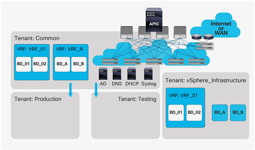
Cisco ACI tenancy model
The Cisco ACI tenancy model facilitates the administrative boundaries of all network infrastructure. Objects in the common tenant can be consumed by any tenant. For instance, in Figure 3, Production and Testing share the same VRF tables and bridge domains from the common tenant.
Figure 4 provides a snapshot of the tenant Networking constructs from the APIC GUI, showing how the VRF tables and bridge domains are independent of the topology and can be used to provide connectivity across a number of workloads, including vSphere, Hyper-V, OpenStack, bare metal, and IP storage solutions.
Flexibility of the Cisco ACI networking model
Endpoints that require a common policy are grouped together into Endpoint Groups (EPGs); an Application Network Profile (ANP) is a collection of EPGs and the contracts that define the connectivity required between them. By default, connectivity is allowed between the endpoints that are part of the same EPG (intra-EPG connectivity). This default can be changed by configuring isolated EPGs (in which connectivity is not allowed), or by adding intra-EPG contracts. Also, by default, communication between endpoints that are members of different EPGs is allowed only when contracts between them are applied.
These contracts can be compared to traditional Layer 2 to Layer 4 firewall rules from a security standpoint. In absence of a contract, no communication happens between two EPGs. Contracts not only define connectivity rules but also include Quality of Service (QoS) and can be used to insert advanced services like load balancers or Next-Generation Firewalls (NGFWs) between any two given EPGs. Contracts are tenant-aware and can belong to a subset of the tenant resources (to a VRF table only) or be shared across tenants.
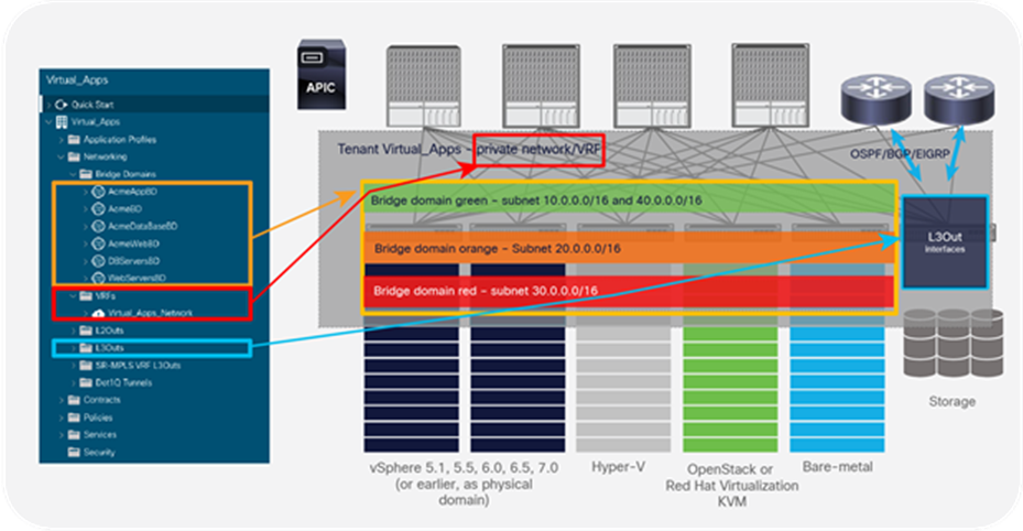
The EPGs of an ANP do not need to be associated to the same bridge domain or VRF table, and the definitions are independent of network addressing. For instance, contracts are not defined based on subnets or network addresses, making policy much simpler to configure and automate. In this sense, ANPs can be seen as constructs that define the application requirements and consume network and security resources, including bridge domains, VRF tables, contracts, or L3Out interfaces. Figure 5 shows an example of a three-tier application with three environments (Production, Testing, and Development) where the Production Web EPG (Web-prod) allows only Internet Control Message Protocol (ICMP) and SSL from the external network accessible through an L3Out interface. Other similar contracts govern connectivity between tiers. Because there are no contracts between the Development and Testing or Production EPGs, the environments are completely isolated regardless of the associated bridge domain or VRF table or IP addresses of the endpoints.
For more information on ACI contracts, please refer to Cisco ACI Contract Guide.
Example of an application network profile for a three-tier application with three environments
From a networking point of view, the fabric implements a distributed default gateway for all defined subnets. This ensures optimal traffic flows between any two workloads for both east-west and north-south traffic without bottlenecks.
At the simplest level, connectivity can be modeled with an ANP using VLANs and related subnets. A simple ANP can contain one or more VLANs associated with an environment represented as one EPG per VLAN associated to a single bridge domain. This still provides the benefit of using the distributed default gateway, eliminating the need for First-Hop Redundancy Protocols and providing better performance, while using contracts for inter-VLAN security. In this sense, Cisco ACI provides flexibility and options to maintain traditional network designs while rolling out automated connectivity from a cloud platform.
Workloads are connected to the fabric using “domains” that are associated to the EPGs. Bare metal workloads are connected through physical domains, and data center routers are connected as external routing domains. For virtualization platforms, Cisco ACI uses the concept of Virtual Machine Management (VMM) domains.
Cisco ACI empowers the fabric administrator with the capability of integrating the APIC with various VMM solutions, including VMware vCenter, VMware NSX-T for Data Center (VMware SDN VMM), Microsoft System Center Virtual Machine Manager (SCVMM), Red Hat Virtualization (RHV), Rancher, OpenShift and OpenStack.
These integrations bring the benefit of consolidated visibility and simpler operations, because the fabric has a full view of physical and virtual endpoints and their location, as shown in Figure 6. APIC can also automate provisioning of virtual networking within the VMM domain.
Once a VMM domain is configured, the APIC has a full view of physical and virtual endpoints
For VMware environments, Cisco ACI provides integrations in two fronts: Cisco ACI VMware VMM domains for vSphere environments and Cisco ACI VMware SDN domains for NSX-T environments.
For vSphere environments, the fabric and vSphere administrators work together to register vCenter with APIC using proper credentials. In addition, it is also possible to install a Cisco ACI plug-in for the vSphere web client. The plug-in is registered with the APIC and uses the latter’s Representational State Transfer (REST) API. The plug-in allows the fabric administrator to provide vCenter administrators with the ability to see and configure of tenant-level elements, such as VRF tables, bridge domains, EPGs, and contracts, as shown in Figure 7, where we see the entry screen of the Cisco ACI plug-in and can observe the various possible functions exposed on the right hand side.
In vSphere environments, when a VMM domain is created in the APIC, it automatically configures a vSphere Distributed Switch (VDS) through vCenter with the uplink settings that match the corresponding Cisco ACI fabric port configurations, in accordance with the configured interface policies. This provides for automation of interface configuration on both ends (ESXi host and Cisco ACI Top-of-Rack [ToR] switch, referred to as Cisco ACI leaf), and ensures consistency of Link Aggregation Control Protocol (LACP), Link Layer Discovery Protocol (LLDP), Cisco Discovery Protocol, and other settings. In addition, once the VMM domain is created, the fabric administrator can see a complete inventory of the vSphere domain, including hypervisors and Virtual Machines. If using the Cisco ACI vCenter plug-in is used, the vSphere administrator can also have a view of the relevant fabric aspects, including non-vSphere workloads (such as bare-metal servers, virtual machines running on other hypervisors, or even Linux containers). The APIC does not need to create the VDS. When defining a vCenter VMM domain, APIC can operate on an existing VDS. In that case, APIC expects the existing VDS to be placed in a folder with the same name as the VDS. Since Cisco ACI Release 3.1, it is also possible to define a VMM domain to vCenter in read-only mode. In read-only mode, APIC will not provision dvPortGroups in the VDS, but the fabric administrator can leverage the added visibility obtained by VMM integration. Cisco ACI VMM integration uses the vCenter northbound API and does not require anything else to work effectively.
The Cisco ACI plug-in for vCenter
Cisco ACI VMware SDN VMM domains are supported from Cisco ACI Release 5.1 for NSX-T environments. On configuring a VMware SDN VMM domain on APIC, APIC configures a VLAN Transport Zone on NSX-T Manager. The Cisco APIC configured VLAN Transport Zone (as seen within the NSX-T Infrastructure), will have the same name as the VMware SDN VMM domain that was created within the Cisco APIC GUI. APIC interacts with the NSX-T Manager Appliance using the latter’s publicly available Representational State Transfer (REST) API.
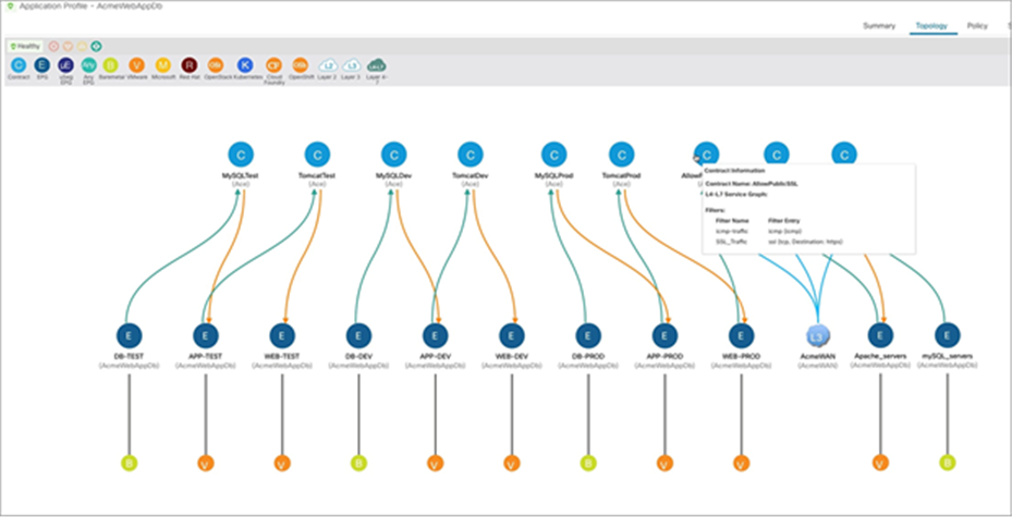
Once the VLAN Transport Zone is deployed on the NSX-T Manager Appliance, a compute manager such as vCenter must be added to NSX-T, and hosts inside the compute manager should be configured with NSX-T. During this configuration of hosts with NSX-T, we add the VLAN Transport Zone onto the host and configure a vSphere Distributed Switch (VDS) to utilize for distributed networking. NSX-T allows you to utilize an existing VDS switch on the host or deploy a new NSX-T controlled Virtual Distributed Switch (N-VDS) on the host. Both of these options can be utilized for VMware SDN VMM domains. Please note that VMware is planning to phase out the support for NSX-T-managed vSphere Distributed Switch (N-VDS) on ESXi hosts sometime in later 2022. N-VDS will still be supported and functional on NSX-T Edge Nodes. You can find more details about N-VDS host switch support deprecation here. The network administrator can now utilize Cisco ACI to provision networking for the NSX-T virtualized workloads using the same application-centric constructs they are familiar with; they can use Cisco ACI contracts to connect and secure the virtualized workloads among one another or with any physical device in the data center. Figure 8, below, shows a topology view of web, application, and database workloads interconnected and secured through ACI constructs. Web and application workloads run in the NSX-T domain connected to Cisco ACI through the VMware SDN VMM domains. The database workload is a bare-metal server connected to ACI through a physical domain.
Application Profile topology showing NSX-T workloads and bare-metal database connected and secured by ACI constructs
In addition, once the VMM domain is created, the fabric administrator can see a complete inventory of the hosts in the NSX-T domain (hosts which are added into the VLAN Transport Zone), including hypervisors and virtual machines.
It is important to note that using a VMM domain enables consolidated network provisioning and operations across physical and virtual domains while using standard virtual switches from the hypervisor vendors. For instance, in the case of Microsoft Hyper-V, APIC provisions logical networks on the native Hyper-V virtual switch, using the open protocol OpFlex to interact with it. Similarly, in OpenStack environments, Cisco ACI works with Open vSwitch using OpFlex and Neutron ML2 or the Group-Based Policy plug-in within OpenStack.[2]
Specifically in the context of this white paper, which focuses on VMware NSX-T environments, the APIC provisions a VLAN Transport Zone for every VMware SDN VMM domain created, which uses a VLAN encapsulation as attach endpoints to the fabric.
NSX-T for Data Center is an evolution of VMware NSX-V. At the heart of the system is the NSX-T Manager Appliance, which is similar to the former NSX-V Manager and is instrumental in managing all other components, from installation to provisioning and upgrading.
NSX-T for Data Center has the following components:
● NSX-T Manager Appliance: Available in a virtual machine form factor, NSX-T Manager Appliance has two major components: a Management Plane (MP) and a Central Control Plane (CCP). Local Control Plane (LCP) is hosted on the workload servers. Prior to NSX-T Release 2.4, NSX-T Manager and NSX-T Controller were two separate individually deployed components; starting from NSX-T Release 2.4, both management and control planes are integrated into NSX-T Manager Appliance.
◦ Management Plane provides entry point to the system for an API as well as an NSX-T graphical user interface. It is responsible for maintaining user configurations, handling user queries, and performing operational tasks on all management, control, and data-plane nodes. Management Plane instructs Control Plane on how to configure the NSX-T fabric to reach the desired state.
◦ Central Control Plane computes the runtime state of the system based on the configuration from Management Plane and disseminates the topology information reported by the data-plane elements, and pushes the stateless configurations to the forwarding engines. NSX-T Control Plane is divided into two parts, Central Control Plane (CCP) and Local Control Plane (LCP). CCP runs on the NSX-T Manager Appliance, and LCP runs on the individual host kernels.
● ESXi Kernel Modules: A set of vSphere installation bundles (vibs) that are installed on each hypervisor host during the NSX-T host configuration process. This allows you to extend the NSX-T management and control planes to the hosts. These kernel modules provide services such as distributed firewall and distributed routing and provide a Local Control Plane (LCP). ESXi Kernel Modules can be deployed on to the hosts through NSX-T Manager Appliance.
● NSX-T Edge Nodes: Can be deployed as a virtual machine or as bare metal. NSX-T Edge Nodes provide connectivity to the physical infrastructure from within the NSX-T fabric. They also provide centralized network services that cannot be distributed to the hypervisors, such as load balancing, Network Address Translation (NAT), and edge firewalls, to name a few. Edge nodes can be grouped into clusters representing a pool of compute capacity that one or more centralized network services can consume.
Some customers may adopt NSX-T for its network virtualization capabilities, while others are interested only in its security features. With the exception of guest introspection security features that are required for the integration of certain technology partner solutions, Cisco ACI provides equivalent functionality to NSX-T and in many cases offers a superior feature set that better meets real-world customer requirements.
NSX-T for Data Center network requirements
Hypervisor-based network overlays such as those provided by VMware NSX-T are intended to provide network virtualization over any physical fabric. Their scope is limited to the automation of GENEVE-based virtual network overlays created between software-based GENEVE Virtual Tunnel Endpoints (VTEPs) running at the hypervisor level. In the case of NSX-T, these software VTEPs are only created within the vSphere Distributed Switch (VDS) or the NSX-T-managed vSphere Distributed Switch (N-VDS) by adding NSX-T kernel modules on workload servers that enable GENEVE functionality.
The virtual network overlay must run on top of a physical network infrastructure, referred to as the underlay network. The NSX-T Manager Appliance does not provide any level of configuration, monitoring, management, or reporting for this physical layer.[3]
VMware’s design guide for implementing NSX-T describes a recommended Layer-3-routed design of the physical fabric or underlay network. The following points summarize the key design recommendations:
● Fabric design:
◦ Promotes a leaf-and-spine topology design with sufficient bisectional bandwidth. When network virtualization is used, mobility domains are expected to become larger and traffic flows between racks may increase as a consequence. Therefore, traditional or legacy designs may be insufficient in terms of bandwidth.
◦ Suggests a Layer 3 access design with redundant ToR switches, limiting Layer 2 within the rack.
◦ Recommends using IP Layer 3 Equal-Cost Multipathing (ECMP) to achieve fabric load balancing and high availability.
◦ Per-rack (per–ToR switch pair) subnets for vSphere infrastructure traffic, including Management, vMotion, IP storage (Small Computer System Interface over IP [iSCSI], Network File Server [NFS]) and NSX-T VTEP pools.
◦ QoS implemented by trusting Differentiated Services Code Point (DSCP) marking from the VDS.
● Server-to-fabric connectivity:
◦ Redundant connections between ESXi hosts and the ToR switches is configured at the VDS level, using either LACP, routing based on originating port, routing based on source MAC, or active/standby.
The Layer-3-access fabric design imposes constraints on the NSX-T overlay design. For example, the NSX Edge Nodes require connecting to VLAN-backed port groups to routes between the NSX-T overlay and any external networks. On a traditional Layer-3 ToR design, those VLANs will not be present across the infrastructure but instead will be limited to a small number of dedicated servers on a specific rack. This is one reason the NSX-T architecture recommends dedicating vSphere clusters to a single function: running NSX Edge Nodes in so-called edge clusters.
Another example is that the VTEP addressing for GENEVE VMKernel interfaces needs to consider per-rack subnets. That requirement can be accomplished by using Dynamic Host Configuration Protocol (DHCP) with option 82 or static NSX-T Manager IP pools.
This design recommendation also promotes a legacy device-by-device operational model for the data center fabric that has hindered agility for IT organizations. Furthermore, it assumes that the network fabric will serve only applications running on ESXi hosts running NSX-T. But for most customer environments, the network fabric must also serve bare-metal workloads, applications running in other hypervisors, or core business applications from a variety of vendors, such as IBM, Oracle, and SAP.
vSphere infrastructure traffic (management, vMotion, virtual storage area network [VSAN], fault tolerance, IP storage, and so forth) that is critical to the correct functioning of the virtualized data center is not considered. Neither is it viewed or secured through NSX-T, and as a result it remains the sole responsibility of the physical network administrator.
From a strategic perspective, the physical fabric of any modern IT infrastructure must be ready to accommodate connectivity requirements for emerging technologies—for instance, clusters dedicated to container-based applications such as Kubernetes, OpenShift, and Mesos.
Finally, just as traffic between user virtual machines needs to be secured within the NSX-T overlay, traffic between subnets for different infrastructure functions must be secured. By placing the first-hop router at each ToR pair, it is easy to hop from the IP storage subnet to the management subnet or the vMotion network and vice versa. The network administrator will need to manage Access Control Lists (ACLs) to prevent this from happening. This means configuring ACLs in all access devices (in all ToR switches) to provide proper filtering of traffic between subnets and therefore ensure correct access control to common services like Domain Name System (DNS), Active Directory (AD), syslog, performance monitoring, and so on.
Customers deploying NSX-T on top of a Cisco ACI Fabric will have greater flexibility to place components anywhere in the infrastructure, and may also avoid the need to deploy of NSX Edge Nodes for perimeter routing functions, potentially resulting in significant cost savings on hardware resources and on software licenses. They will also benefit from using Cisco ACI contracts to implement distributed access control to ensure infrastructure networks follow an allowed-list–zero-trust model.
Running vSphere Infrastructure as an application with Cisco ACI
vSphere Infrastructure has become fundamental for a number of customers because so many mission-critical applications now run on virtual machines. At a very basic level, the vSphere infrastructure is made up of the hypervisor hosts (the servers running ESXi), and the vCenter servers. vCenter is the heart of vSphere and has several components, including the Platform Services Controller, the vCenter server itself, the vCenter SQL database, Update Manager, and others. This section provides some ideas for configuring the Cisco ACI fabric to deploy vSphere infrastructure services. The design principles described here apply to vSphere environments regardless of whether they will run NSX-T.
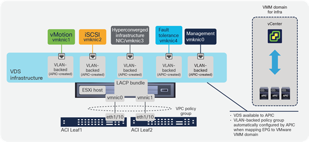
The vSphere infrastructure generates different types of IP traffic, as illustrated in Figure 9, including management between the various vCenter components and the hypervisor host agents, vMotion, storage traffic (iSCSI, NFS, VSAN). This traffic is handled through kernel-level interfaces (VMKernel network interface cards, or VMKNICs) at the hypervisor level.
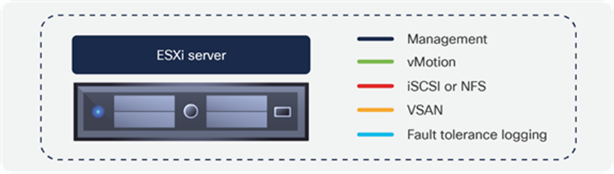
ESXi VMKernel common interfaces
From a data center fabric perspective, iSCSI, NFS, vMotion, fault tolerance, and VSAN are all just application traffic for which the fabric must provide connectivity. It is important to note that these applications must also be secured, in terms of allowing only the required protocols from the required devices where needed.
Lateral movement must be restricted at the infrastructure level as well. For example, from the vMotion VMKernel interface there is no need to access management nodes, and vice versa. Similarly, VMKernel interfaces dedicated to connecting iSCSI targets do not need to communicate with other VMKernel interfaces of other hosts in the cluster. And only authorized hosts on the management network need access to vCenter, or to enterprise configuration management systems like a puppeteer.
In traditional Layer 3 access fabric designs, where each pair of ToR switches has dedicated subnets for every infrastructure service, it is very difficult to restrict lateral movement. In a Layer 3 access design, every pair of ToRs must be the default gateway for each of the vSphere services and route toward other subnets corresponding to other racks. Restricting access between different service subnets then requires ACL configurations on every access ToR for every service Layer 3 interface. Limiting traffic within a service subnet is even more complicated—and practically impossible.
Cisco ACI simplifies configuring the network connectivity required for vSphere traffic. It also enables securing the infrastructure using Cisco ACI contracts. The next two sections review how to configure physical ports to redundantly connect ESXi hosts and then how to configure Cisco ACI logical networking constructs to enable secure vSphere traffic connectivity.
Physically connecting ESXi hosts to the fabric
ESXi software can run on servers with different physical connectivity options. Sometimes physical Network Interface Cards (NICs) are dedicated for management, storage, and other functions. In other cases, all traffic is placed on the same physical NICs, and traffic may be segregated by using different port groups backed by different VLANs.
It is beyond the scope of this document to cover all possible options or provide a single prescriptive design recommendation. Instead, let’s focus on a common example where a pair of physical NICs is used to obtain redundancy for ESXi host-to-fabric connectivity. In modern servers, these NICs could be dual 10/25GE or even dual 40GE.
When using redundant ports, it is better to favor designs that enable active/active redundancy to maximize the bandwidth available to the server. For instance, when using Cisco ACI GX or FX leaf models, access ports support 25/40 Gbps. With modern server NICs also adding 25/40G Ethernet support, it becomes affordable to have 50/80 Gbps of bandwidth available to every server.
Note that Cisco also offers Nexus switches that provide 100G server connectivity but at the writing of this document very few servers are deployed with 100G NICs.
In Cisco ACI, interface configurations are done using leaf policy groups. For redundant connections to a pair of leaf switches, a VPC policy group or access policy group with MAC-pinning on VMM vSwitch Port Channel Policy is required. Policies Groups are configured under Fabric Access Policies in the ACI GUI. Within a policy group, the administrator can select multiple policies to control the interface behavior. Such settings include Storm Control, Control Plane Policing, Ingress or Egress rate limiting, LLDP, and more. These policies can be reused across multiple policy groups. For link redundancy, port-channel policies must be set to match the configuration on the ESXi host. Table 1 summarizes the options available in vSphere distributed switches and the corresponding settings recommended for Cisco ACI interface policy group configuration.
Table 1. Cisco ACI port-channel policy configuration
| vSphere Distributed Switch (VDS) Teaming and Failover Configuration |
Redundancy Expected with dual VMNIC per host |
ACI Interface Policy Configuration |
| Route Based on originating virtual port |
Active/Active |
MAC Pinning |
| Route based on Source MAC Hash |
Active/Active |
MAC Pinning |
| Route based on physical NIC load |
Active/Active |
MAC Pinning-Physical-NIC-load |
| LACP (802.3ad) |
Active/Active |
LACP Active, LACP Passive: |
| Route Based on IP Hash |
Active/Active |
Static Channel Mode On |
| Explicit Failover Order |
Active/Standby |
Use Explicit Failover Order |
Of the options shown in Table 1, we do not recommend Explicit Failover Order (Active/Standby), as it keeps only one link active. We recommend Active/Active options such as MAC Pinning and LACP to utilize multiple links.
MAC Pinning provides the following benefits:
● MAC Pinning provides active/active load balancing.
● Configuration is easy and simple. Whereas LACP requires different ACI vPC/Port-Channel interface policy group per port-channel/ESXi host, an access interface policy with MAC Pinning on VMM vSwitch Port Channel Policy can be reused for multiple ESXi hosts connectivity.
LACP provides the following benefits:
● LACP is an IEEE standard (802.3ad) implemented by all server, hypervisor, and network vendors.
● LACP is well understood by network professionals and enables active/active load balancing.
● LACP negotiation provides a protection from mis-cabling of physical links.
● LACP enables very fast convergence on the VMware VDS, independent of the number of virtual machine or MAC addresses learned.
The original LACP implementation on VMware vSphere, beginning with version 5.1, assumes that all network adapters, or VMNICs, are part of the same port channel (or Link Aggregation Group). Enhanced LACP was introduced in VMware vSphere 5.5; it offers more flexibility about how to aggregate the VMNICs in port channels and which load-balancing (hashing) option to use to forward traffic. Cisco ACI offers support for the enhanced LACP configuration starting from Cisco ACI Release 4.0. Hence, you can configure Cisco ACI for either the original VMware vSphere LACP implementation or for enhanced LACP.
For more information on ESXi connectivity options and configuration steps, refer Cisco ACI Design Guide.
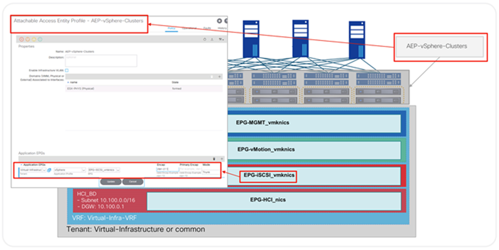
Another key setting of the interface policy groups is the Attachable Entity Profile (AEP). AEPs can be considered the “where” of the fabric configuration and are used to group domains with similar requirements.
AEPs are tied to interface policy groups. One or more domains (physical or virtual) can be added to an AEP. Grouping domains into AEPs and associating them enables the fabric to know where the various devices in the domain live, and the APIC can push and validate the VLANs and policy where it needs to go.
AEPs are configured in the Global Policies section in Fabric Access Policies. Specific for vSphere, ESXi hosts can be connected to the fabric as part of a physical domain or a Virtual Machine Manager (VMM) domain, or both. An AEP should be used to identify a set of servers with common access requirements. It is possible to use anything from a single AEP for all servers to one AEP per server at other extreme. The best design is to use an AEP for a group of similar servers, such as one AEP per vSphere cluster or perhaps one AEP per NSX-T transport zone. In Figure 10, for instance, we show a VPC Policy Group associated with an AEP for the particular vSphere environment that has both a VMM and a Physical domain associated.
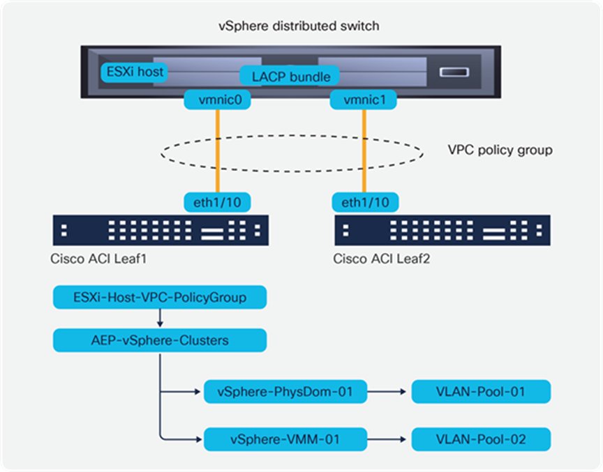
ESXi host connected using a VPC policy group
Each domain type will have associated encapsulation resources, such as a VLAN or VXLAN pool. Having interface configurations such as VPC policy groups associated to AEPs simplifies several tasks, for instance:
● Network access that must be present for all servers of a particular kind can be implemented by associating the relevant EPGs to the AEP directly. For example, all ESXi hosts in a particular vSphere environment require connections to vMotion, Management, or IP storage networks. Once the corresponding EPGs are attached to the AEP for the ESXi hosts, all leaf switches with connected ESXi hosts are automatically configured with those EPG network encapsulations and the required bridge domains, Switch Virtual Interfaces (SVIs), and VRF tables, without any further user intervention.
● Encapsulation mistakes can be identified and flagged by the APIC. If the network administrator chooses a VLAN pool for a group of servers or applications, the VLAN ID pool will be assigned to the corresponding domain and, by means of the AEP, associated to relevant interfaces. If a VLAN from the wrong pool is then chosen by mistake for a port or VPC connecting to a particular server type (as identified by the AEP), the APIC will flag an error on the port and the EPG.
Mapping vSphere environments to Cisco ACI network and policy model
The Cisco ACI solution provides multiple options for achieving various levels of isolation for applications. You can use different VRF tables to achieve Layer 3 level isolation, use different bridge domains and EPGs for Layer 2 isolation, and use contracts to implement Layer 2–4 access control between or within EPGs.
In addition, the fabric administrator can also leverage the Cisco ACI tenancy model to create administrative isolation on top of logical network isolation. This can be useful for customers that have development or testing environments that must be completely isolated from production, or in environments where fabric resources are shared by multiple organizations.
For an IT organization without specific requirements for multi-tenancy, vSphere infrastructure traffic is probably well served by keeping it under the common tenant in Cisco ACI. As mentioned earlier, the common tenant facilitates sharing resources with other tenants. Also, because the common tenant is one of the APIC system tenants, it cannot be deleted.
That said, for administrative reasons, it may be desirable to keep a dedicated tenant for infrastructure applications such as vSphere traffic. Within this tenant, connectivity for vSphere and other virtualization platforms and associated storage is configured using Cisco ACI application profiles. This method allows the fabric administrator to benefit from the APIC automatically correlating events, logs, statistics, and audit data specific to the infrastructure. Figure 11 shows a tenant called Virtual-Infrastructure and indicates how the fabric administrator can see at a glance the faults that impact the tenant. In this view, faults are automatically filtered out to show only those relevant to infrastructure traffic.
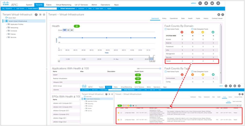
View of tenant-level fault aggregation in APIC
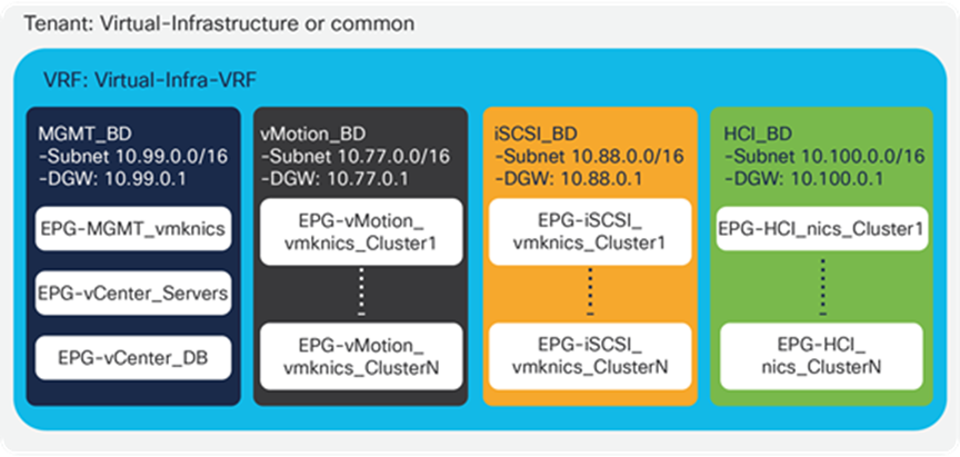
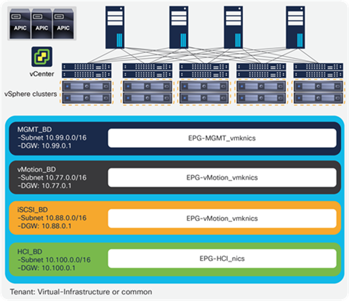
From a networking perspective, we recommend using different bridge domains for different vSphere traffic types. Figure 12 shows for a configuration example with a bridge domain and an associated subnet for each of the main types of traffic: management, vMotion, IP storage, hyper-converged storage (for example, VMware vSAN or Cisco HyperFlex™ server nodes). Each bridge domain can be configured with large subnets, and can expand across the fabric, serving many clusters. In its simplest design option, all VMKernel interfaces for specific functions are grouped into a single EPG by traffic type.
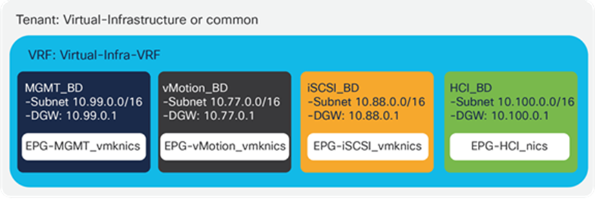
Configuration example with a bridge domain and associated subnet for each main traffic type
Within each Bridge Domain, traffic sources are grouped into EPGs. Each ESXi host therefore represents not one but a number of endpoints, with each VMKernel interface being an endpoint in the fabric with different policy requirements.
Within each of the infrastructure bridge domains, the VMKernel interfaces for every specific function can be grouped into a single EPG per service as shown in Figure 12.
Obtaining per-cluster visibility in APIC
The previous model of one EPG or bridge domain per vSphere service enables the simplest configuration possible. It is similar to legacy deployments where a single VLAN is used for all vMotion VMKNICs, for instance, albeit with the benefits of a distributed default gateway, Layer 2 and Layer 3 ECMP, and so forth.
Although simple is usually good, such an approach limits the understanding of the vSphere infrastructure at the network level. For example, if you have 10 vSphere clusters, each of which has 32 servers, you will have 320 endpoints in the vMotion EPG. By looking at any two endpoints, it is impossible to understand if vMotion traffic was initiated by vCenter, as is the case inside a VMware Distributed Resource Scheduler (DRS) cluster, or by an administrator, if it was between two clusters.
It may be convenient to represent the vSphere cluster concept in the network configuration. The Cisco ACI EPG model enables fabric administrators to accomplish this without imposing changes in the IP subnetting for the services.
For instance, VMKernel interfaces for each function may be grouped on a per-rack or per-vSphere-cluster basis. Again, this does not have to impact subnetting, as multiple EPGs can be associated to the same bridge domain, and therefore all clusters can still have the same default gateway and subnet for a particular traffic type. This approach, shown in Figure 13, enables more granular control and provides a simple and cost-effective way for the fabric administrator to get visibility by cluster. APIC automatically correlates statistics, audit, event correlation, and health scores at the EPG level, so in this way, they represent per-rack or per-cluster level. An alternative design can make use of per-cluster EPG for each traffic type. This option requires extra configuration that is easy to automate at the time of cluster creation. An orchestrator such as vRealize Orchestrator can create the EPG at the same time the cluster is being set up. This method has no impact on IP address management, as all clusters can still share the same subnet, and it takes advantage of APIC automatic per-application and per-EPG statistics, health scores, and event correlation.
Configuration example with VMKernel interfaces grouped by function and Cluster
Let’s continue looking at vMotion traffic as an example. Within a vSphere cluster, all VMKernel interfaces for vMotion are grouped into an EPG. EPG traffic statistics now represent vMotion within the cluster. Figure 14 shows how the fabric administrator can look at the tenant-level statistics to view an aggregate of all the traffic for the entire vSphere infrastructure (not virtual machine traffic, only infrastructure traffic), and then drill down into vMotion-specific traffic to identify a spike, and finally check that vMotion activity was within a specific EPG for the COMPUTE-01 cluster.
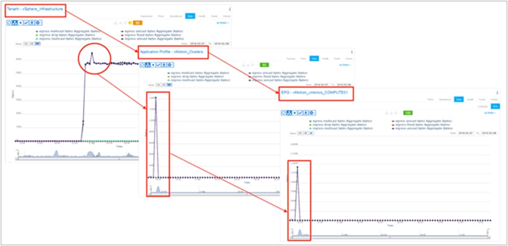
Monitoring vMotion-specific traffic on a per-cluster basis
The same approach works for iSCSI, Cisco HyperFlex, or VSAN traffic. It is convenient for troubleshooting and capacity planning to be able to correlate traffic volumes to a specific cluster and/or to communications between clusters.
Table 2 summarizes the recommended bridge domains, their settings, and associated EPGs to provide vSphere infrastructure connectivity, whether single or multiple EPGs are used.
Table 2. Recommended bridge domains, settings, and EPGs for vSphere infrastructure connectivity
| Bridge Domain |
Settings |
Subnet(s) |
EPGs |
| Hardware Proxy: Yes ARP Flooding: Yes L3 Unknown Multicast Flooding: Flood Multi Destination Flooding: Flood in BD Unicast Routing: Yes Enforce Subnet Check: No |
Management Ex. 10.99.0.0/16 |
MGMT_vmknics vCenter_Servers vCenter_DB |
|
| vMotion_BD |
Hardware Proxy: Yes ARP Flooding: Yes L3 Unknown Multicast Flooding: Flood Multi Destination Flooding: Flood in BD Unicast Routing: Yes Enforce Subnet Check: No |
vMotion Subnet Ex. 10.77.0.0/16 |
vMotion_vmknics_Cluster1 vMotion_vmknics_Cluster2 … vMotion_vmknics_ClusterN |
| Storage_BD |
Hardware Proxy: Yes ARP Flooding: Yes L3 Unknown Multicast Flooding: Flood Multi Destination Flooding: Flood in BD Unicast Routing: Yes Enforce Subnet Check: No |
iSCSI Subnet Ex. 10.88.0.0/16 |
Storage_vmknics_Cluster1 Storage_vmknics_Cluster2 … Storage_vmknics_ClusterN |
A common question is whether a subnet must be configured under the bridge domain for services that will not be routed. For instance, for services like vMotion, NFS, or iSCSI you have the option not to configure a subnet on the bridge domain. However, if no subnet is configured, then Address Resolution Protocol (ARP) flooding must be configured when hw-proxy is used. ARP flooding is not strictly required, as long as a subnet is configured on the bridge domain, if for example, the Cisco ACI spines will do ARP gleaning when hw-proxy is configured and IP routing is checked on the bridge domain.
Securing vSphere Infrastructure
The designs outlined above include examples of using a single EPG per service and multiple EPGs per service. When all vMotion VMKNICs are on the same EPG it is clear that vMotion can work, because the default policy for traffic internal to an EPG is to allow all communications. When using multiple EPGs, however, the default is to block all communication between different EPGs. Therefore, for the model in Figure 13 to work and allow intercluster vMotion, this default zero-trust model must be changed.
One way is to place all the EPGs in Figure 13 in the “preferred group.” Another way is to disable policy enforcement on the VRF table where these EPGs belong. In those two ways, the fabric behaves like a traditional network, allowing traffic connectivity within and between subnets.
However, it is safer and recommended to implement a zero-trust approach to infrastructure traffic. Let’s use the vMotion example from the previous section to illustrate how to use the Cisco ACI contract model to secure the vSphere infrastructure using a zero-trust model.
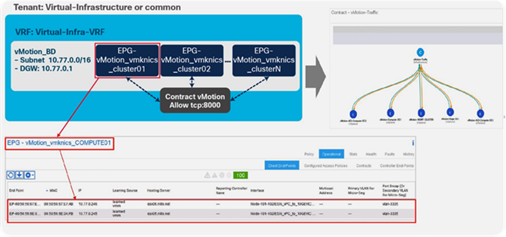
In the design where an EPG is used for each service and cluster, intercluster vMotion communication requires inter-EPG traffic. Fabric administrators can leverage the Cisco ACI contract model to ensure that only vMotion traffic is allowed within the vMotion EPG or between vMotion EPGs (or both).
Figure 15 shows an example where per-cluster EPGs have been configured for vMotion, all within the same bridge domain (same subnet). A contract called vMotion-Traffic is configured that allows only the required ports and protocols for vSphere vMotion.[4] This contract can be associated to all vMotion EPGs. To allow vMotion traffic between clusters, all vMotion EPGs will consume and provide the contract. To allow vMotion traffic within a cluster, but restricted to vMotion ports and protocols, each vMotion EPG will add an Intra-EPG contract association. Once this is done, only vMotion traffic is accepted by the network from the vMotion VMKernel interfaces; the fabric will apply the required filters on every access leaf in a distributed way. The same concept can be applied to NFS, iSCSI, management, and so forth: contracts can be used to allow only the required traffic.
Fabric administrators must pay special attention when configuring intra-EPG contracts. Support for intra-EPG contracts requires Cisco ACI Release 3.0 or later and is provided only on Cisco Nexus EX and FX leaf switches or later models. In addition, when intra-EPG contracts are used, the fabric implements proxy ARP. Therefore, when the contract is applied to an EPG with known endpoints, traffic will be interrupted until the endpoint ARP cache expires or is cleaned. Once this is done, traffic will resume for the traffic allowed by the contract filters. (This interruption is not an issue in green field deployments.)
For more information on ACI contract and its security features, refer ACI Contract Guide.
Configuration with multiple vSphere DRS clusters using per-cluster vMotion EPGs
The fabric administrator has a view of specific VMKernel interfaces, easily mapping the IP address or MAC address to the appropriate access leaf, access port, or VPC with cluster context and filter information, as shown in Figure 15.
One primary advantage of the EPG model for vSphere infrastructure is the security enhancement it provides. Another important advantage is operational, as it is easy for each vSphere administrator to view statistics and health scores by cluster, as illustrated in Figure 14.
VMware vSwitch design and configuration considerations
Another important consideration is how to map EPGs to port group configurations in vCenter. The vSphere VDS can be connected to the Cisco ACI leaf switches as a physical domain, as a VMware VMM domain, or both.
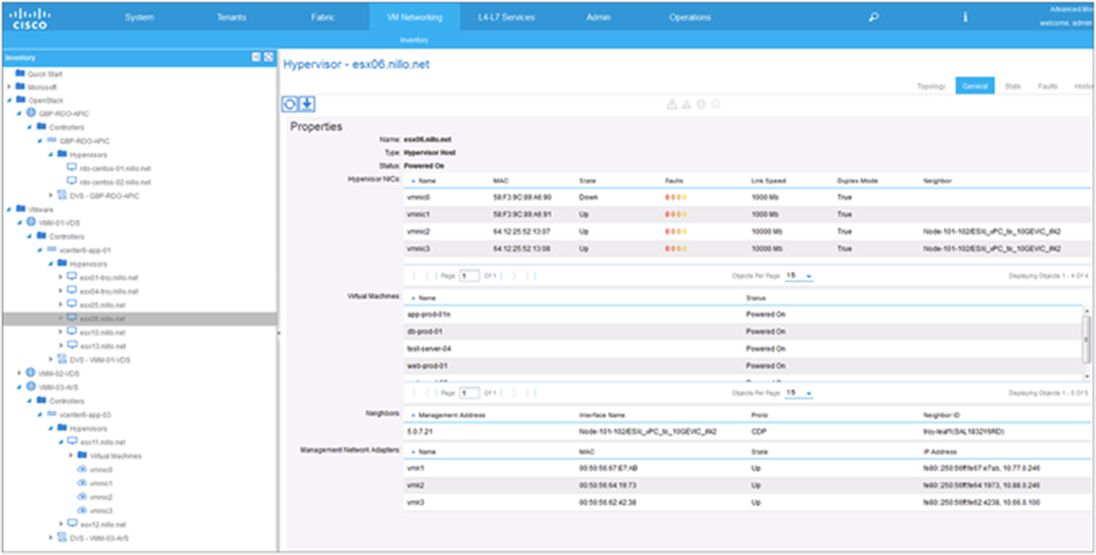
Using a VMware VMM domain integration provides various benefits. From a provisioning standpoint, it helps ensure that the vSwitch dvUplinks are configured in a way that is consistent with the access switch port configuration. It also helps to automate creating dvPortGroups with the correct VLAN encapsulation for each EPG and to avoid configuring the EPG on specific access switches or ports. From an operational standpoint, using a VMware VMM domain increases the fabric administrator’s visibility into the virtual infrastructure, as shown in Figure 16.
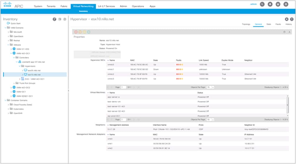
Example of data from one hypervisor in of one of the VMM domains
When using a VMM domain, the APIC leverages vCenter’s northbound API to get access to the VDS, giving the fabric administrator several advantages:
● Ensures that the dvUplinks configurations of the VDS match those of the fabric.
● Monitors the VDS statistics from the APIC, to view dvUplinks, VMKNIC, and virtual machine–level traffic statistics.
● Automates dvPortGroup configurations by mapping EPGs created on APIC to the VMware VMM domain. APIC creates a dvPortGroup on the VDS and automatically assigns a VLAN from the pool of the VMware VMM domain, thus completely automating all network configurations.
● Automates EPG and VLAN provisioning across physical and virtual domains. When the vCenter administrator assigns VMKNIC to a dvPortGroup provisioned by the APIC, the latter automatically configures the EPG encapsulation on the required physical ports on the switch connecting to the server.
● Enables the fabric administrator to have a contextual view of the virtualization infrastructure. APIC provides a view of the vCenter inventory and uses it to correlate virtual elements with the fabric.
Figure 17 represents a VDS with redundant uplinks to a Cisco ACI leaf pair. The VDS can be automatically created by APIC when the VMware VMM domain is configured, or it can be created by the vCenter administrator prior to VMware VMM configuration. If it was created by the vCenter administrator, the fabric administrator must use the correct VDS name at the moment of creation of the VMware VMM domain. The APIC ensures that the uplink port groups, or dvuplinks, have the correct configuration.
VDS with redundant uplinks to a Cisco ACI leaf pair
When the fabric administrator creates EPGs for vSphere services, as in Figures 12 and 13 earlier in the document, they only need to associate the EPGs to the VMM domain. No further configuration is required; the APIC configures the required dvPortGroups and physical switch ports automatically.
If a VMware VMM domain is not used, then the EPGs for vSphere infrastructure must be mapped to a physical domain. The dvPortGroups must be configured separately by the vCenter administrator using the VLAN encapsulation communicated by the fabric administrator. In this case, it is best to use statically assigned VLANs.
The fabric administrator then needs to configure the required EPGs on the access leaf switches. Although the VMM configuration offers the simplest configurations, Cisco ACI offers advantages in simplicity and automation compared to traditional fabrics also when using physical domains.
For instance, going back to the design in Figure 12, which is partially reproduced in Figure 18, we can see that this design approach is extremely simple to configure in Cisco ACI, even for large deployments using physical domains.
Assuming that an Attachable Entity Profile (AEP) has been configured for ESXi servers in a particular vSphere environment, it is sufficient to associate the EPGs from Figure 12 to the corresponding AEP. The APIC will take care of automatically configuring the correct VLAN encapsulation and the distributed default gateway for the corresponding subnet in every leaf switch where the AEP is present. Adding new ESXi hosts requires only configuring a VPC and selecting the correct AEP, nothing more. As illustrated in Figure 18, associating the service EPGs to the AEP, automatically provisions all the required VLAN encapsulation, bridge domains, SVIs, and VRF tables on all required access switches.
Configuring EPGs at the AEP used on all VPC policy groups for all ESXi hosts on the vSphere clusters
Cisco recommends using VMware VMM domains for the simplified configuration and enhanced visibility they provide, as outlined above. Table 3 compares the use of VMM to that of physical domains, specifically in the context of vSphere infrastructure.
Table 3. Comparing VMM and physical domains for vSphere infrastructure
|
|
VDS Connection to ACI |
|
| Physical domain |
VMM domain |
|
| Not required |
Required |
|
| dvUplinks port configuration |
Manually by virtual administrator |
Automated by APIC |
| dvPortGroups configuration |
Manually by virtual administrator |
Automated by APIC |
| VLAN assignment |
Static |
Dynamic or static |
| EPG configuration on leaf switches |
Static path or EPG mapped to AEP, or both |
Automated by APIC |
| Virtual Machine Kernel Network Interface Card (VMKNIC) visibility in the fabric |
IP and MAC addresses |
IP and MAC addresses, hypervisor association and configuration |
| Virtual Machine Network Interface Card (VMNIC) visibility in the fabric |
Not available |
Hypervisor association, faults, statistics |
| Virtual machine level visibility |
IP and MAC addresses |
Virtual machine objects, virtual NIC configuration, statistics |
| Consolidated statistics |
Not available |
APIC can monitor VDS statistics |
Starting with Cisco ACI Release 3.1, it is also possible to configure a read-only VMM domain. In that mode, APIC always interfaces with an existing VDS and in view-only mode. A read-only VMM domain does not enable automated configurations by APIC but provides many of the visibility capabilities outlined above.
As in the case with vCenter VMM integration, starting with Cisco ACI Release 5.1, Cisco ACI integrates with VMware NSX-T, utilizing VMware SDN VMM domains on the APIC.
Option 1. Running NSX-T security and virtual services using a Cisco ACI–integrated overlay for network virtualization
Some customers are interested in using VMware NSX-T security capabilities, or perhaps using NSX-T integration with specific ecosystem partners, but do not want to incur the complexity associated with running the NSX-T overlay, such as deploying and operating two different fabrics in physical infrastructure and NSX-T fabric, Edge Nodes, distributed logical routers, utilizing physical devices in the data center for service insertions between NSX-T workloads, and so forth. Sometimes separation of roles must also be maintained, with network teams responsible for all network connectivity and virtualization or security teams responsible for NSX-T security features.
These customers can utilize the integrated overlay capabilities of the Cisco ACI fabric for automated and dynamic provisioning of connectivity for applications while using the NSX-T network services such as the virtual load balancer, distributed firewall, microsegmentation, and other NSX-T security components and NSX-T technology partners.
Using NSX-T Distributed Firewall and Cisco ACI–integrated overlays
This design alternative uses supported configurations on both Cisco ACI and VMware NSX-T. The Cisco ACI fabric administrator works with the VMware NSX-T Administrator to define a VMware SDN VMM domain on the APIC for NSX-T integration, as described in earlier parts of this document.
The VMware SDN VMM domain enables APIC to have visibility into the hypervisor hosts configured with the VLAN Transport Zone from the NSX-T inventory. As of the writing of this document, VMware SDN VMM domains only support VLAN transport zones. The APIC VMware SDN VMM domain integration interacts with the NSX-T Manager Appliance in the same way as when PowerShell, vRealize Orchestrator, or another orchestration system is used, through NSX-T’s public northbound API.
Once the VMware SDN VMM domain has been established, the APIC configures a VLAN transport zone with the same name as the VMware SDN VMM domain created on NSX-T Manager Appliance. Afterward, the NSX-T administrator will add the hosts that need networking into the APIC-deployed VLAN transport zone. During this one-time setup phase, NSX-T administrator configures whether to utilize the existing vSphere Distributed Switch (VDS) on the host or to deploy an NSX-T-managed vSphere Distributed Switch (N-VDS), and choose the uplink utilized by these VDSs. This is when NSX-T installs and configures NSX kernel modules onto the ESXi hosts, along with the N-VDS if chosen. Please note that VMware is planning to phase out the support for NSX-T-managed vSphere Distributed Switch (N-VDS) on ESXi hosts sometime later in 2022. N-VDS will still be supported and functional on edge nodes. You can find more details about N-VDS host switch support deprecation here. With that in mind, this document focuses on VDS switches, but any of the configurations discussed in this document can be applied to both VDS and N-VDS host switches.
The option to deploy NSX-T security features without adding the edge nodes and GENEVE overlay configuration is well known to vCloud Networking and Security. The NSX-T Distributed Firewall, microsegmentation, guest introspection, and data security features are fully functional and can work without the use of NSX-T overlay networking features. This type of installation is shown in Figure 19.
In this model of operation, the connectivity requirements for virtual machine traffic are provisioned on Cisco APIC by creating bridge domains and EPGs and associating EPGs with VMware SDN VMM domains, instead of creating logical switches, logical routers, and edge nodes. The required bridge domains and EPGs can be configured on the APIC from a variety of interfaces, including the APIC GUI, NX-OS CLI, or APIC REST API; through a cloud- management platform or by Infrastructure as Code (IaC) and configuration management tools such as Terraform and Ansible. The APIC also supports out-of-the-box integration with key cloud-management platforms, including VMware vRealize Automation, and others, to automate these configurations.
In a nutshell, instead of deploying NSX Edge Nodes and Tier-0, Tier-1 logical routers, and configuring NSX logical switches, the administrator defines VRF tables, bridge domains, and EPGs and maps the EPGs to the VMware SDN VMM domain. Virtual machines are connected to the NSX-T dvPortGroups created by these EPGs via the NSX-T Manager. NSX-T dvPortGroups are dvPortGroups launched by NSX-T, functionally they are similar to dvPortGroups created directly on the VDS.
We recommend using a different Cisco ACI tenant for virtual machine data traffic from the one used for vSphere Infrastructure connectivity. This method ensures isolation of user data from infrastructure traffic as well as separation of administrative domains. For instance, a network change for a user tenant network can never affect the vSphere infrastructure, and vice versa.
Within the user tenant (or tenants), network connectivity is provided using VRF tables, bridge domains, and EPGs with associated contracts to enable Layer-3 and Layer-2 forwarding as described for infrastructure traffic earlier in this document. Virtual machines leverage Cisco ACI distributed default gateway technology in hardware to enable optimal distributed routing without performance compromises, regardless of the nature of the workload (physical, virtual, containers) or traffic flow (east-west and north-south).
We can illustrate this model using a classic example of a three-tier application with web, application, and database tiers, as shown in Figure 19. The web and app tiers are running in vSphere virtual machines. The database tier is running in bare. Additional requirements include low-latency access from the WAN, load balancing, and secure connectivity between tiers.
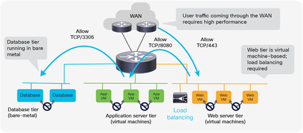
A typical three-tier application with a nonvirtualized database
This setup can be configured using the fabric for distributed routing and switching. Figure 20 shows a VRF table, three bridge domains for the various application tiers, and an L3Out interface to connect to endpoints external to the fabric. Cisco ACI provides distributed routing and switching. Connectivity between bare metal and virtual machines is routed internally in the fabric, and connectivity with external endpoints is routed through physical ports that are part of L3Out.
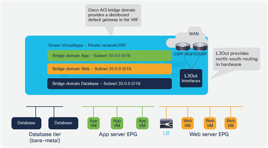
The ACI fabric provides programmable distributed routing and switching for all workloads
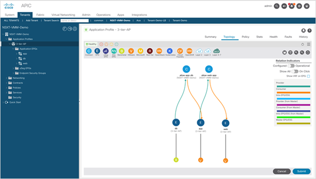
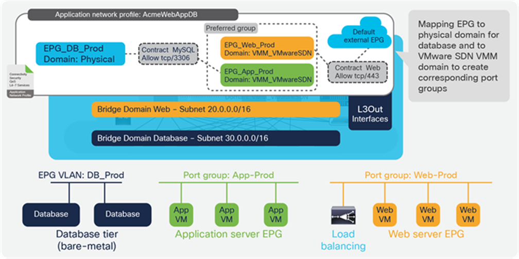
Figure 21 shows the rest of the logical configuration, with three EPGs corresponding to our application tiers (web, application, and database). The DB_Prod EPG is mapped to a physical domain to connect bare-metal databases, while the Web_Prod and App_Prod EPGs are mapped to the NSX-T VMM domain so that the APIC automatically creates corresponding NSX-T dvPortGroups on the VDS, by automatically configuring a VLAN-backed logical switch on NSX-T using standard NSX-T API calls to NSX-T Manager Appliance. The NSX-T dvPortGroups are backed using locally significant VLANs that are dynamically assigned by APIC. All routing and switching functionality is done in hardware in the Cisco ACI fabric. The default gateway for virtual machines is implemented by the distributed default gateway on every Cisco ACI leaf switch that has attached endpoints on those EPGs. The EPGs can map to both virtual and physical domains and enable seamless connectivity between virtual machines and nonvirtual devices. In the NSX-T domain, each EPG corresponds to a dvPortGroup that is automatically created by APIC by means of the VMware SDN VMM domain integration.
In Figure 21, the Web_Prod and App_Prod EPGs are also placed in the preferred group, allowing unrestricted connectivity between these EPGs, just as if they were logical switches connected to a Tier-1 logical router. The only difference from using the NSX-T Tier-1 logical router is that, if two virtual machines are located on the same ESXi host, traffic is routed at the leaf. However, on a given vSphere cluster utilizing NSX-T, only a small percentage of the traffic can ever stay local in the hypervisor, and switching through the leaf provides low-latency line rate connectivity.
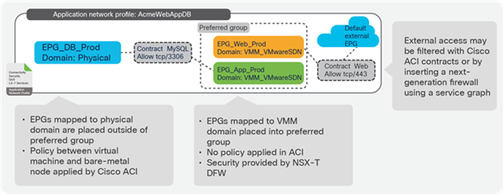
Basic example of an application network profile, with three EPGs and contracts between them
In this way, the administrator can easily ensure that all EPGs created for connecting virtual machines (mapped to the VMware SDN VMM domain) can be placed in the preferred group, and policy will be controlled using the NSX-T Distributed Firewall (DFW).
The advantage of this model of network virtualization is that no gateways are required when a virtual machine needs to communicate with endpoints outside the NSX-T domain. In addition, as the NSX-T DFW cannot configure security policies for physical endpoints, the DB_Prod EPG, and any other bare metal or external EPG can be placed outside of the Preferred group, and Cisco ACI contracts can be used to provide security. This functionality is not limited to communication with bare metal. For instance, in the same way, the fabric administrator can enable a service running on a Kubernetes cluster to access a vSphere virtual machine utilizing NSX-T without involving any gateways.
The vSphere administrator can create virtual machines and place them into the relevant NSX-T dvPortGroups using standard vCenter processes, API calls, or both. This process can be automated through vRealize Automation or other platforms. The virtual machines can then communicate with other virtual machines in the different application tiers as per the policies defined in the NSX-T DFW. All routing and bridging required between virtual machines happens in a distributed way in the fabric hardware using low-latency switching. This method means that virtual machines can communicate with bare metal servers or containers on the same or on different subnets without any performance penalties or bottlenecks. Security policies between endpoints that are not inside the NSX-T workload domain can be configured using Cisco ACI contracts.
The vSphere ESXi hosts have the NSX-T kernel modules running, and the NSX-T administrator can use all NSX-T security features, including NSX-T Distributed Firewall and Data Security for Guest Introspection, as shown in Figure 22. The administrator can also add antivirus or antimalware partner solutions.
Example of NSX-T security features: NSX-T distributed firewalls are used to create security rules for application and web tiers routed by the Cisco ACI fabric
The approach of combining NSX-T security features with Cisco ACI integrated overlay offers the clear advantage of better visibility, as shown in Figure 23. Virtual machines that are part of a security group are also clearly identified as endpoints in the corresponding EPG.
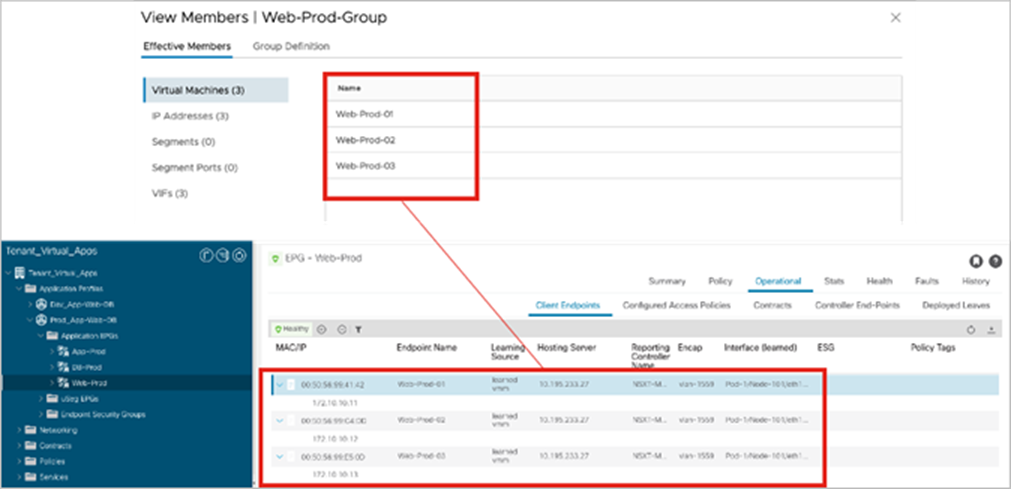
Virtual machines that are part of an NSX-T groups are visible inside the APIC EPG
It is important to note that, in this model, the use of Cisco ACI contracts is entirely optional. Since we are assuming that the NSX-T DFW will be used to implement filtering or insert security services, the fabric administrator may choose to disable contract enforcement inside the VRF tables to eliminate the need for contracts. However, instead of completely disabling policy inside the VRF, we recommend placing EPGs mapped to the VMware SDN VMM domain in the Preferred group to allow open communication between them while allowing the fabric administrator to use contracts for other EPGs inside the same VRF.
This design approach does not limit NSX-T to security features only. Other services, such as using the Edge Nodes for load balancing, can also be used.
Full-featured firewalls are also capable of filtering based on URLs, DNS, IP options, packet size, and many other parameters. In addition, Next-Generation Firewalls (NGFWs) are also capable of performing deep packet inspection to provide advanced threat management.
It may be desirable to insert more advanced security services to protect north-south or east-west traffic flows, or both. In this context, east-west commonly refers to traffic between virtual machines in vSphere clusters with a common NSX-T installation. Any other traffic must be considered north-south for NSX-T, even if it is traffic to endpoints connected in the fabric.
The need for service insertion is not limited to NGFWs but also to other security services such as next-generation network intrusion prevention, or to advanced Application Delivery Controllers (ADCs) that can also perform SSL offload in hardware for high-performance web applications. Figure 24 illustrates the various insertion points available in this design. Because Cisco ACI provides the overlay where all endpoints are connected, organizations can use Cisco ACI service graphs and Policy-Based Redirect to insert services such as physical and virtual NGFWs between tiers without affecting NSX-T service insertion.
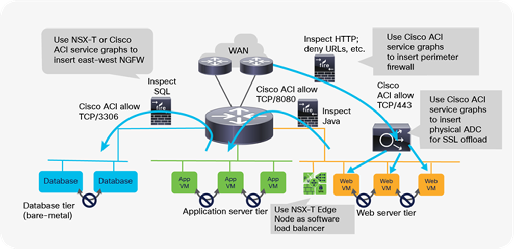
Advanced services can be added using both Cisco ACI and NSX-T service partners
Option 2: Running NSX-T overlays as an application of the Cisco ACI fabric
Using the Cisco ACI integrated overlay offers many advantages, and customers who look at NSX-T to implement better security for their vSphere environments are encouraged to follow that model.
Here we will explain instead how to best configure Cisco ACI in the case where customers also use NSX-T overlay capabilities.
This section describes various alternatives for running NSX-T GENEVE overlay capabilities on a Cisco ACI fabric. Figure 25 shows a general representation of the reference architecture for NSX-T as outlined in the NSX-T for Data Center Design Guide. In the NSX-T reference architecture, VMware recommends dedicating compute resources for user applications and for running NSX-T Edge Nodes, all connected through a leaf-and-spine fabric to maximize bisectional bandwidth. In the figure, servers that cannot be part of the NSX-T overlay are shown in blue, including bare-metal servers, other hypervisors, container platforms, and vSphere clusters without NSX-T installed.
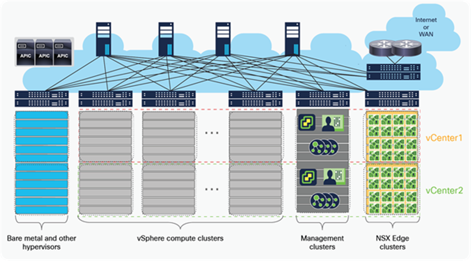
Compute clusters, management cluster, and edge cluster for a multiple vCenter solution
In the NSX-T architecture, the NSX-T Manager Appliance is the heart of the system. The NSX-T Manger Appliance has Management Plane, Control Plane, and policy integrated into it.
The NSX-T reference design shown in Figure 25 makes a clear distinction between ESXi compute clusters dedicated to running applications (that is, vSphere clusters running user or tenant virtual machines), and those clusters dedicated to running NSX-T routing and services virtual machines (that is, NSX Edge Nodes as VMs or bare-metal). The architecture calls these dedicated clusters compute clusters and edge clusters.
VMware Validated Design documents for Software-Defined Data Center (SDDC) also described “converged” designs, in which an edge-node virtual machine can coexist with the user’s virtual machines, eliminating the need for edge clusters. The key implication, as we will see, is that edge-node virtual machines that route between the NSX-T overlay and the rest of the IT infrastructure require that routing configurations and policies be defined on the physical switches they connect to. For this reason, at scale, it becomes complicated, if not impossible, to enable the edge-node virtual machines to be placed anywhere in the infrastructure, especially when using a Layer-3-access leaf-and-spine fabric design. This limitation does not occur when using Cisco ACI.
NSX-T GENEVE—Understanding BUM traffic replication
The NSX-T network virtualization capabilities rely on implementing a software GENEVE tunnel endpoint (VTEP) on the vSphere Distributed Switch (VDS). This is accomplished by adding NSX-T kernel modules to each ESXi host. The hypervisor software’s lifecycle management is thereby tied to that of NSX-T. The NSX-T kernel modules are programmed from the NSX-T Manager Appliance.
During the NSX-T host preparation process for an ESXi cluster, the NSX-T administrator enables GENEVE on ESXi clusters from the NSX-T Manager. This process requires selecting a VDS that already exists on the host, during the NSX-T host preparation process. At this time, a new VMKernel interface is created on each ESXi host on the given cluster using a dedicated TCP/IP stack specific to the VTEP traffic. The NSX-T Manager also creates a new dvPortGroup on the VDS. The GENEVE VMKNIC is placed in that dvPortGroup and given an IP address: the NSX-T VTEP address. The NSX-T VTEP address can be configured through either DHCP or an NSX-T Manager–defined IP pool.
The NSX-T VTEP IP address management must be considered carefully, because it may have an impact on how NSX-T handles broadcast, unknown unicast, and multicast traffic (known, collectively, as BUM traffic). NSX-T can handle BUM replication in two ways:
● Hierarchical two-tier (MTEP): Also known as MTEP. In NSX-T the tunnel endpoint table has entries for host-VNI connections. VNIs are like VLANs: in NSX-T, each logical switch or segment has a VNI associated with it. If host-1 has three logical switches, A, B, and C with VNIs 5000, 5001, and 5002, respectively. The tunnel endpoint table will have host-1 added to VNI 5000, 5001, and 5002 as entries. Similarly, the tunnel endpoint table will have entries for all the hosts. If host-1 needs to send a BUM frame on VNI 5000, it refers the tunnel endpoint table to find other hosts with the VNI 5000 on it. This way host-1 knows the TEP endpoints of the other hosts with VNI 5000. After identifying the TEP endpoints host-1 handles the BUM traffic in the following manner:
◦ TEP IPs in the same subnet: For each of the hosts with TEP IPs in the same subnet as host-1, host-1 creates a separate copy of every BUM frame and sends the copy directly to the hosts.
◦ TEP IPs in different subnets: For hosts with TEP IPs in different subnets, for each subnet there may be one or more hosts. For all the destination hosts in each subnet, host-1 nominates one of these destination hosts to be a replicator, and creates a copy of every BUM frame and sends them to the replicator with the frame flagged as a replicate locally in the encapsulation header. Host-1 does not send copies to the other hosts in the same subnet. It becomes the responsibility of the replicator to create a copy of the BUM frame for every host with TEP in the same subnet and as the VNI associated to it in the tunnel endpoint table.
● Head (source): Also known as headend replication or source replication, host-1 simply creates a copy of each BUM frame for each and every host containing the same VNI (VNI 5000), regardless of TEP being in the same subnet or in different subnets.
If all host TEPs are in the same subnets, then the choice of replication does not matter, as both modes send copies of every BUM frame to every other host containing the destination VNI. If the host TEPs are in different subnets, then hierarchical two-tier replication helps distribute the load among multiple hosts. Hierarchical two-tier is the default option of BUM traffic replication. However, the user has an option to select the BUM replication model to use while deploying an overlay logical switch.
NSX-T transport zones
As part of the NSX-T GENEVE configuration, the administrator must also define a transport zone to which ESXi clusters are mapped. A transport zone defines the scope of GENEVE logical switches in Manager mode (while in policy mode, these are referred to as “segments”) in NSX-T overlays. This mapping determines which virtual machines can access a specific logical network based on the cluster to which they are associated.
More importantly, as mentioned, the transport zone defines the scope of a logical switch. A logical switch is a dvPortGroup backed by a GENEVE segment or a VLAN segment created by NSX-T and is limited to a single transport zone. This means that virtual machines in different transport zones cannot be in the same Layer-2 segment or use the same NSX-T constructs. Scalability limits also define how many vSphere DRS clusters can be part of a transport zone, so the scope of a logical switch is limited not by the physical network but by the supported server count per NSX-T transport zone (limited to 1024 servers in NSX-T Release 3.1). At scale, a typical NSX-T deployment therefore consists of multiple transport zones, requiring careful consideration for vSphere Distributed Switch (VDS) transport zone design, and the alignment and connectivity between them. Virtual machines connected to different transport zones must communicate through gateways routing between them.
NSX-T VTEP subnetting considerations
When considering the NSX- T replication models explained earlier in this document, it will be clear that VTEP subnetting has important implications for the system’s behavior. For instance, if we imagine 250 VTEPs in a subnet, when using HEAD replication mode or hierarchical two-tier replication mode, an ESXi host in the worst-case scenario would have to create 250 copies for each received BUM packet. The same setup, using hierarchical two-tier replication mode and with TEP IPs in different subnets would reduce the load on the server, as the host needs to replicate one packet for every other subnet different to its own TEP subnet.
When deploying a traditional Layer-3 access fabric, subnetting for NSX-T VTEPs offers a single choice: one subnet per rack. This statement has three important implications:
● It becomes complicated to use NSX-T Manager IP pools for VTEP addressing unless vSphere clusters are limited to a single rack.
● Using DHCP for VTEP addressing requires configuring DHCP scopes for every rack, using option 82 as the rack discriminator.
● Applying security to prevent other subnets from accessing the VTEP subnets requires configuring ACLs on every ToR switch.
In contrast, when using a Cisco ACI fabric, subnets can span multiple racks and ToR switches, or even the entire fabric, for greater simplicity and flexibility in deployment. Deploying NSX-T on Cisco ACI enables customers to use IP pools or DHCP with complete flexibility.
Running NSX-T GENEVE on a Cisco ACI fabric
NSX-T GENEVE traffic must be associated to on a Cisco ACI bridge domain. NSX-T Geneve traffic will primarily be unicast, but depending on configuration, it may also require multicast. This requirement will influence the Cisco ACI bridge domain configuration; the best configuration will depend on the NSX-T BUM replication model that is prevalent in the design. Administrators can select the BUM replication mode when configuring an overlay logical switch; the default option selected is hierarchical two-tier.
The following two sections cover the recommended Cisco ACI bridge domain and EPG configurations for NSX-T VTEP traffic for hierarchical two-tier and HEAD replication modes.
Bridge domain–EPG design when using NSX-T hierarchical two-tier replication
It is possible to use a single bridge domain and a single subnet for all NSX-T VTEPs when using hierarchical two-tier mode replication for BUM traffic. However, in that case, headend replication performed by NSX-T at the ingress hypervisor may have a significant negative impact on the performance of the NSX-T overlay, especially for environments with a larger number of ESXi hosts and consequently a larger number of VTEPs.
For this reason, when using NSX-T hierarchical two-tier replication mode, we recommend using one bridge domain and subnet per vSphere cluster or per rack. In Layer-3 fabrics, it is not possible to do this per cluster if the clusters expand across multiple racks. This fact is yet another reason to use Cisco ACI as the underlay for NSX-T, as opposed to a traditional Layer-3 fabric. The capability of Cisco ACI for extending a bridge domain wherever needed across the fabric allows for maximum flexibility: vSphere clusters can be local to a rack, or they can expand across racks. But it is better to tie the subnet to the cluster, not the rack. By tying the VTEP subnet to the cluster, the NSX-T administrator can still use NSX-T IP pools to address the VTEP interfaces, defining them by cluster, and is not forced to use DHCP as the only option. Alternatively, DHCP relay can be configured at the bridge domain level, if that is the selected option for NSX-T VTEP IP address management.
Figure 26 illustrates how using one bridge domain or EPG per cluster allows the same VLAN to be used for all the VMKNIC NSX-T GENEVE configuration. This method requires configuring local VLAN significance on the policy groups if the clusters will expand onto multiple racks but raises no problems because two EPGs can use the same VLAN on the same leaf, if the EPGs belong to different bridge domains, as is the case here.
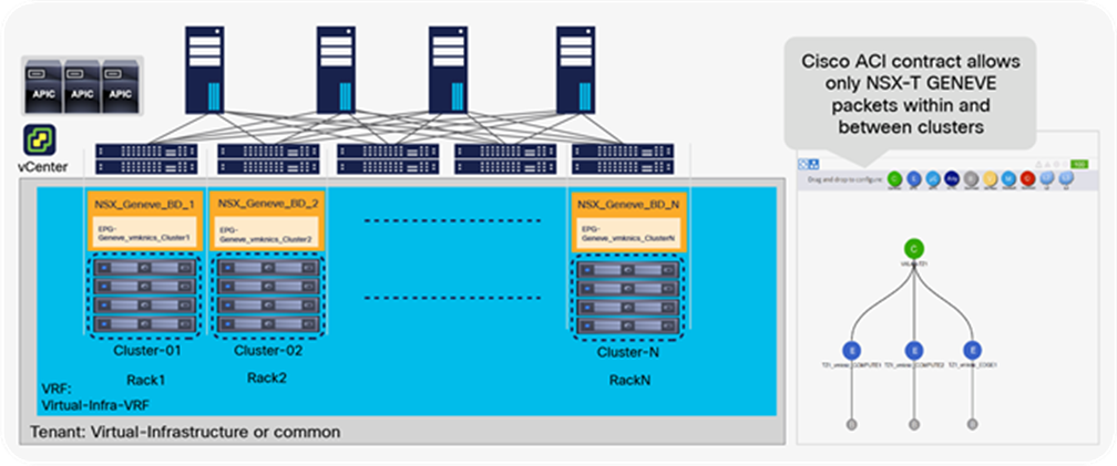
A design using different NSX-T VTEP subnets per cluster, each with a dedicated bridge domain and EPG in Cisco ACI
Bridge domain–EPG design when using NSX-T HEAD replication mode
HEAD replication mode handles TEP IP in the same or different subnets in a similar fashion. The source host is going to create a copy for each of the destination hosts regardless of the subnet. However, even though this simplifies configuration, in large deployments this would create significant negative performance impact on the source host. For this reason, NSX-T HEAD replication mode is not a recommended deployment. But if a user wishes to configure HEAD replication to handle BUM traffic, the user can utilize a single bridge domain with a single or multiple subnets under one EPG for all TEPs inside the NSX-T workloads.
Providing visibility of the underlay for the vCenter and NSX-T administrators
Regardless of the design chosen, much of the operational information in the APIC can be made available to the NSX-T or vCenter administrator leveraging the APIC API. Cisco ACI offers a vCenter plug-in that is included with the APIC license. The Cisco ACI vCenter plug-in is extremely lightweight and uses the APIC API to provide visibility of the Cisco ACI fabric directly from within vCenter, as shown in Figure 27. Using this tool, the NSX-T administrator can leverage the vCenter web client to confirm that the fabric has learned the correct IP or MAC address for NSX-T VTEPs, to view security configurations in Cisco ACI, to troubleshoot fabric-level VTEP-to-VTEP communication, and more. The vSphere administrator can also use the plug-in to configure or view tenants, VRF tables, bridge domains, and EPGs on the APIC. Figure 27 shows the EPGs related to an NSX-T transport zone, including the GENEVE contract and NSX-T VTEPs inside an EPG.
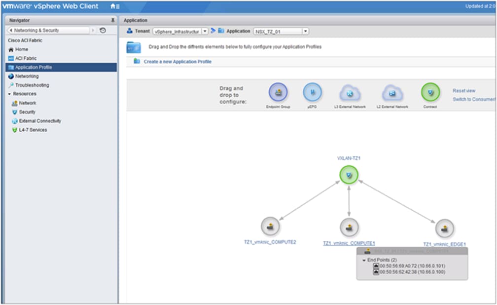
A view of the NSX VTEP EPGs for various clusters as seen from the Cisco ACI vSphere plug-in
The Cisco ACI fabric also provides excellent visibility and troubleshooting tools built in to the APIC. One example is the troubleshooting wizard available on the APIC to monitor details of the endpoints in the topology. Let’s imagine that there are connectivity problems between any two given ESXi hosts. The fabric administrator can use the Cisco ACI Visibility and Troubleshooting tool to have APIC draw the topology between those two hosts. From this tool, we can quickly pull all the statistics and packet drops for every port (virtual or physical) involved in the path between the referred endpoints. We can also pull all events, configuration change logs, or failures that are specific to the devices involved in the path during the time window specified, and we also can pull in the statistics of the contract involved.
Other troubleshooting tools accessible from the same wizard help the fabric administrator configure a specific SPAN session inject traffic to simulate the protocol conversations end to end across the path, and the like. This visibility is available on the APIC for any two endpoints connected to the fabric, whether they are virtual or physical.
Virtual switch options: Single VDS versus dual VDS
Previous sections describe how to best provide NSX-T connectivity and security requirements in terms of using Cisco ACI constructs such as VRF tables, bridge domains, application network profiles, EPGs, and contracts.
As explained earlier, NSX-T GENEVE settings require an existing VDS. We can choose the switch to be utilized for NSX-T while configuring transport nodes. One design approach is to have one VDS dedicated solely for NSX-T logical switches and their corresponding dvPortGroups and to have another VDS dedicated for vSphere infrastructure traffic, such as vMotion, IP storage, and management. This approach is illustrated in Figure 28. The infrastructure VDS is managed by APIC through vCenter using a VMware VMM domain, and the former connects to Cisco ACI using a physical domain and is dedicated to NSX-T traffic. The NSX-T VTEP dvPortGroups is created on this VDS by the NSX-T Manager Appliance, and all logical switches are created on this VDS.
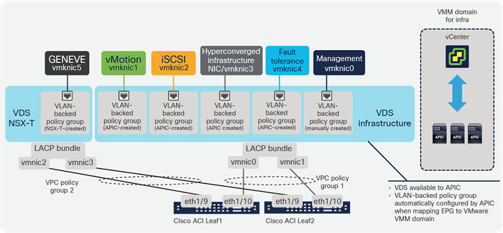
Dual-VDS design with separate VDS for vSphere infrastructure and for NSX-T
We recommend using a Cisco ACI VMware VMM domain for managing and monitoring the VDS for infrastructure traffic, as described in the previous sections, and to keep a separate domain for the NSX-T GENEVE and its corresponding logical switches. Configuring a VMware VMM domain in the APIC for the vCenter gives the fabric administrator maximum visibility into the vSphere infrastructure, while the vSphere administrator retains full visibility through the use of native vCenter tools, and deploying vSphere clusters becomes much easier.
The downside of dedicating one VDS for infrastructure and another for virtual machine data is that more uplinks are required on the ESXi host. However, considering the increasing relevance of hyperconverged infrastructure and IP storage in general, it is not a bad idea to have separate 10/25/40GE for user data and storage.
Alternatively, to reduce the number of uplinks required, customers can run the NSX-T GENEVE VMKernel interface on the same VDS used for vSphere infrastructure traffic. This way, the APIC can have management access to the same VDS through the vCenter API. Cisco has tested and validated this configuration. The VMM domain configuration on Cisco ACI and the corresponding VDS must be provisioned before NSX-T host preparation. The configuration of the GENEVE VMKernel interface is done by the NSX-T Manager Appliance in any case, and therefore should not be done by mapping the GENEVE EPG to the VMM domain. All logical switch dvPortGroups are created on the same VDS. The NSX-T GENEVE VMKernel interface must always be attached to an EPG mapped to a physical domain.
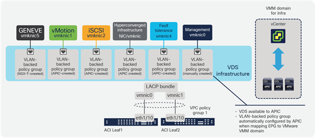
Single-VDS design using same VDS for vSphere infrastructure and NSX-T
Using VMware VMM integration may also be convenient when considering the edge clusters. The compute resources required for running NSX Edge Node virtual machines will need to participate on the NSX-T overlay, and they will also need communication with the physical network. The connectivity between the NSX-T Edge Node virtual machines and the physical network must be done using standard dvPortGroups backed by VLANs. These edge node uplink dvPortGroups are not automated through NSX-T, nor are they created from the NSX-T Manager Appliance.
As we will see in the following sections, the dvPortGroups used for connecting NSX-T Edge Node virtual machine uplinks to the physical world can be configured by creating EPGs that provide the required connectivity and policy and then mapping those EPGs to the specific VMware VMM domain. This method helps in automating the connection of the edge nodes to the physical world and provides additional benefits in terms of mobility, visibility, and security.
NSX-T edge clusters—NSX-T routing and Cisco ACI
Introduction to NSX-T routing
When using NSX-T GENEVE overlays, traffic that requires connecting to subnets outside of the overlay must be routed through NSX-T Edge Nodes. Edge nodes can be deployed in a virtual machine form factor or as bare-metal. NSX-T does not perform any automation of the physical network. However, the edge nodes require connection to the physical network for routing. Since legacy networks lack programmability, to minimize physical network configurations, some VMware documentation recommends concentrating all edge nodes in dedicated clusters. This way, network administrators do not need to know which ToR to configure for edge node network connectivity as all edge nodes will appear in the same rack. This approach can lead to suboptimal use of compute resources. On one hand, it is possible for the vSphere clusters dedicated to running edge nodes to be under-provisioned in capacity, in which case application performance will suffer. On the other hand, the opposite may happen and edge clusters could be overprovisioned, wasting compute resources and associated software licenses. This section discusses how best to connect edge nodes to the Cisco ACI fabric to minimize or eliminate these constraints.
Edge clusters follow the same designs presented in previous sections in terms of NSX-T VTEP configuration. Specifically, a GENEVE VMKNIC is created for NSX-T VTEP addresses, and it must be connected to the required EPG in the Cisco ACI fabric.
An NSX-T Edge Node is a transport node that runs the local control-plane demons and forwarding engines implementing the NSX-T data plane. It runs an instance of the NSX-T virtual switch called the NSX Virtual Distributed Switch (N-VDS). Edge nodes are service appliances that provide pools of capacity and are reserved to running network services that are not distributed down to the hypervisors, for example, centralized services.
Routing in NSX-T is handled by two fundamental components: a Distributed Router (DR) and a Service Router (SR). DR, as the name suggests, is distributed in nature and is present on all transport nodes the transport zone belongs to, which includes edge nodes. DR is responsible to carry out the east-west routing in NSX-T, whereas SR is a centralized component and present only on the edge nodes. SR is responsible for providing centralized services, such as Network Address Translation (NAT), load balancers, Layer 2-4 edge firewalls, etc. More importantly, SR is responsible for north-south routing or connecting to the physical infrastructure. Dynamic routing protocols such as Border Gateway Protocol (BGP) and Open Shortest Path First (OSPF) can be run on the SR neighboring with the physical router in the data center.
Tier-1 and Tier-0 are the two types of logical routers you can create in NSX-T. Both of these logical routers can have Distributed Router (DR) and Service Router (SR) components. These logical routers are tied to a transport zone and have a 1:1 relationship. In other words, a logical router can belong to one and only one transport zone.
Once a logical router is configured on NSX-T, either a Tier-1 or a Tier-0 logical router, a DR corresponding to that logical router is instantiated on all the transport nodes that belong to the transport zone linked to the logical router. When a centralized service is initialized (centralized services can be hosted on both Tier-0 and Tier-1 logical routers), or when the logical router is connected to an external physical router (connecting to external fabric is only possible by a Tier-0 router), an SR is initialized on the edge node and an internal link called an intra-tier transit link is auto-created using a transit logical switch between the DR and SR. This is how a VM attached to a DR component of the logical router can communicate with the external physical fabric or the centralized service.
Most NSX-T overlay designs consist of both Tier-0 and Tier-1 logical routers and follow a two-tiered routing architecture that enables the management of networks at the provider (Tier-0) and tenant (Tier-1) tiers. The provider routing tier is attached to the physical network for north-south traffic, and the tenant routing context can connect to the provider Tier-0 and manage east-west communications. In this scenario, both Tier-1 and tier-0 logical routers instantiate DRs on all the transport nodes including the edge node that belong to the transport zone linked to the logical router. An SR component is deployed on the edge node only when a centralized service such as NAT, LB, etc., is instantiated on the logical routers or when a VLAN interface is created on the tier-0 logical router and connected to the physical fabric. After the SR is deployed, an intra-tier link is auto-created by NSX-T, establishing connectivity between the DR and SR.
An NSX-T Edge Node virtual machine has a maximum of four uplinks: one for management, one for overlay, and two for VLAN uplinks. The Tier-0 router hosted on the edge node can have a maximum of two uplinks to ToR through the edge node VLAN uplinks connected to the dvPortGroups backed by a VLAN.
NSX-T Tier-1 logical routers are always in active/standby HA mode, whereas, the Tier-0 logical routers can be configured in active/standby or active/active HA mode, Centralized services such as Network Address Translation (NAT), load balancers, and Layer 2-4 edge firewalls cannot be instantiated on a Tier-0 logical router when it is running in active/active HA mode.
Edge nodes with similar topology are grouped together into edge clusters. In a scenario with an edge cluster having two edge nodes as members, a Tier-0 logical router routing to the physical fabric and deployed on the edge cluster will have a Service Router (SR) instantiated on both the edge nodes. When using an active/standby HA configuration, only one SR on one edge node is active; the other SR on the other edge node is in standby mode. In this configuration the active SR can utilize only one active uplink from the edge node out of the possible two. If the Tier-0 router is deployed in active/active mode, the SRs on both edge nodes are active and can forward traffic. Even in this mode, each Service Router (SR) can have only one active uplink per edge node. To utilize the maximum of two uplinks per edge node, and to increase the north-south bandwidth, the active/active Tier-0 router must have ECMP enabled. NSX-T supports a maximum of eight ECMP paths.
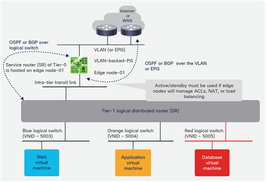
Typical two-tier minimum logical routing design with NSX-T
In some deployments, the Tier-0 router on the edge nodes does not need to run a dynamic routing protocol, most often when the subnets on the Tier-1 or Tier-0 router use RFC1918 private address space and the Tier-0 router performs Network Address Translation (NAT) to a given routable address.
In such scenarios, some NSX-T designs propose adding a third routing tier inside the overlay, such as that shown in Figure 31. In that model, different tenants may get RFC1918 subnets for their applications and route outside toward a Tier-0 logical router’s SR that performs Network Address Translation (NAT). ThoseTier-0 logical routers connect using another transit logical switch to an ECMP edge node set (edge cluster) that hosts a Tier-0 logical router that performs routing to external subnets.
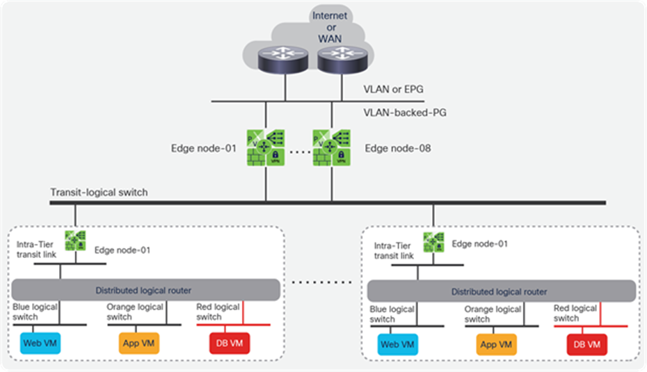
Typical scalable three-tier overlay routing design with NSX-T
The sections that follow describe how best to connect Tier-0 logical routers to the Cisco ACI fabric for these three scenarios:
● Tier-0 logical router running NAT to the Cisco ACI fabric. Tier-0 logical router does not do dynamic routing.
● Tier-0 logical router running dynamic routing through the fabric. Tier-0 logical router peers with another router, not with the Cisco ACI fabric.
● Tier-0 logical router running dynamic routing peering with the fabric. Tier-0 logical router peers with the Cisco ACI fabric border leaf switches.
Regardless of the routing scenario, the edge node is always a transport node and will have at least three NICs. The configurations of the virtual NICs are done while deploying the edge nodes VM from the NSX-T Manager Appliance. The first virtual NIC connects directly to the management network. The second virtual NIC connects to the GENEVE overlay network; this is done by adding an overlay transport zone to the edge node and connecting the overlay N-VDS (an N-VDS is created in the edge node while adding the transport zone to the transport node) to an overlay dvPortGroup connected to the GENEVE TEP EPG in ACI. Similarly, the third virtual NIC connects to the physical network by adding a VLAN transport zone to the edge node and configuring the VLAN N-VDS uplink to connect to a VLAN-backed dvPortGroup port connected to an external routing domain. Edge nodes in bare-metal form factor also follow the same networking architecture.
It is important to note that a single edge node can have one and only one Tier-0 logical router hosted on it. When initialized, an edge node is just an empty container with N-VDS switches; it does not do anything until the Tier-0 logical router is connected to the physical network or until a centralized service is initialized. The logical routers utilize the edge node N-VDS dvPortGroups to form downlinks to overlay networks and uplinks to the physical fabric.
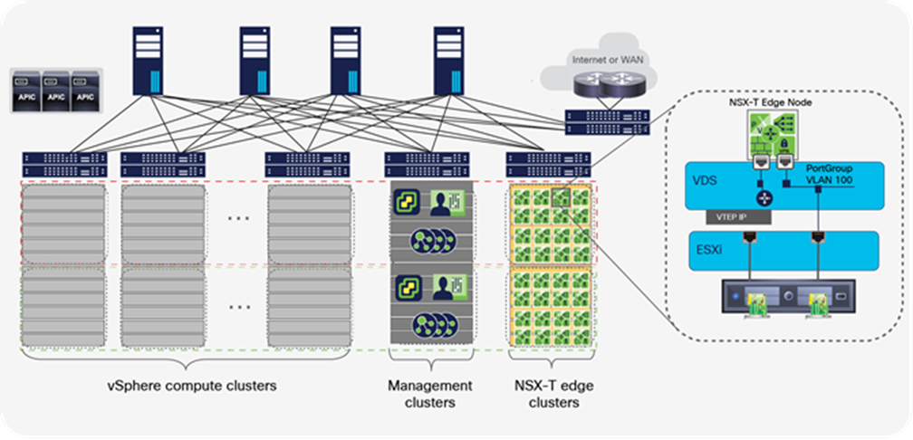
Representation of the edge-node virtual machine with two vNICs, one connected to the overlay and one to the physical network (management vNIC not shown)
Connecting Tier-0 logical router with NAT to the Cisco ACI fabric
In certain cloud solutions it is common to use RFC1918 private address spaces for tenant subnets, for instance, in certain topologies deployed with vCloud Director or vSphere Integrated OpenStack. In those cases, the private subnets are configured at the Tier-1 logical router, and the Tier-0 logical router will have one or more routable addresses that it uses to translate addresses for the Tier-1 logical router private subnets.
From a Cisco ACI fabric perspective, a Tier-0 logical router performing NAT does not require routing configurations because it appears as a regular endpoint in an EPG. The simplest design in Cisco ACI is to create a bridge domain for the subnet that will be used to provide addresses for the NAT pool of the Tier-0 logical router. The Tier-0 logical router default route will point to the bridge domain default gateway IP address. The uplink dvPortGroup for the Tier-0 logical router will correspond with an EPG where the Tier-0 logical router appears connected. Figure 32 shows a Tier-0 logical router with two links, one connected to a VLAN-backed dvPortGroups that in turn would connect to a Cisco ACI EPG. In this design, the additional Tier-0 logical router shown in Figure 31 to provide routing using ECMP between the NSX-T Tier-0 logical router and the rest of the world is not required. The fabric can route between different NSX-T Tier-0 logical routers and, toward other subnets connected to the same Cisco ACI fabric, or also, as shown in Figure 33, toward subnets external to the Cisco ACI fabric through an L3Out interface.
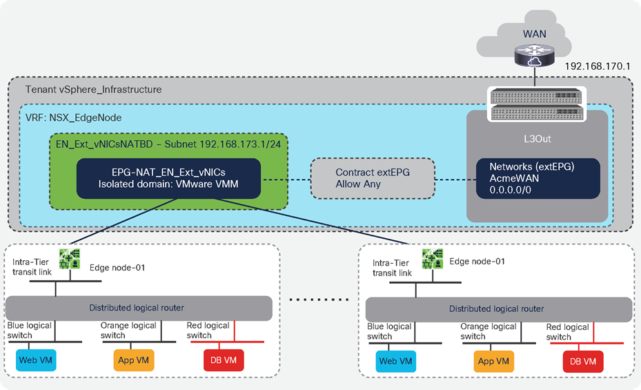
NSX-T tenant edge node perform NAT and connects to a Cisco ACI EPG. The Cisco ACI fabric provides all routing required between edge-node virtual machines and any other subnet
In this case, with Cisco ACI it is very simple to eliminate the need for the second tier of Tier-0 logical routers by leveraging the L3Out model in the fabric, as depicted in Figure 33. This configuration is simple to implement and to automate. It also has great benefits in terms of performance and availability. Performance-wise, any traffic switched from an NAT Tier-0 logical router toward an endpoint attached to the fabric will benefit from optimal routing, directly from the first connected leaf switch. Traffic toward addresses external to the fabric will go through Cisco ACI L3Outs that use 10GE, 40GE, or 100 GE links with hardware-based, low-latency and low-jitter line-rate throughput. The design in Figure 33 is far better than routing through a second tier of Tier-0 logical routers shown in Figure 31. It is also more cost-effective, as no additional edge nodes are required for a second tier of Tier-0 logical routers. Availability-wise, as of this writing, it is impossible to guarantee sub-second convergence reacting to any failure vector affecting a Tier-0 logical router (be it a link, switch, server, or edge node failure). However, by reducing or eliminating reliance on Tier-0 logical routing and performing it in the fabric, customers achieve better availability from eliminating failure vectors and because Cisco ACI provides subs-second convergence on switch or link failures.
Finally, this configuration can also help customers benefit financially. By reducing the number of Tier-0 logical routers required, customers require fewer servers to deploy edge nodes, fewer vSphere and NSX-T licenses, and fewer network ports to connect them.
Tier-0 logical router routing through the fabric
When not doing NAT, more often than not the Service Router (SR) of the Tier-0 logical router hosted on the edge node is running a dynamic routing protocol with external routers and with the distributed routers of Tier-0 and Tier-1. The Distributed Router (DR) of the Tier-1 logical router announces connected subnets to the Service Router (SR) of the Tier-0 logical router that will propagate them to the routers outside of the NSX-T overlay. Generally, in two-tier routing topology of NSX-T, logical switches are connected to the Tier-1 logical router, and multiple Tier-1 logical routers are connected to the Tier-0 logical router. However, logical switches can be directly attached to the Tier-0 router and maintain a single-tier routing topology. The Distributed Router (DR) component of Tier-0 and Tier-1 logical routers provides a distributed default gateway that runs on the hypervisor distributed router kernel module and provides routing between virtual machines connected to the logical switches attached to the distributed routers. However, for external connectivity, traffic is sent to the Service Router (SR) of the Tier-0 logical router, which removes the GENEVE header and routes the packets into a VLAN to reach external routes.
Typically, the data center routers are physically connected to the Cisco ACI fabric. If it is expected that each Tier-0 logical router will route only to subnets external to the Cisco ACI fabric, the Tier-0 logical router hosted on the edge node may be peering with data center routers. In this case, it is only necessary to provide the Layer-2 path between the router interfaces and the edge node’s external vNIC. In such a scenario, the Cisco ACI fabric does Layer-2 transit between the Tier-0 logical router and the data center routers using regular EPGs. Route peering is configured between the Tier-0 logical routers and the external routers, as illustrated in Figure 34, which shows the edge node uplink port group corresponding to an EPG for the edge node external vNICs on the same bridge domain as the EPG used to connect the WAN router ports. Note that the edge nodes and the data center routers are connected to different leaf switches simply for illustration purposes. They can be connected to the same leaf switches or not.
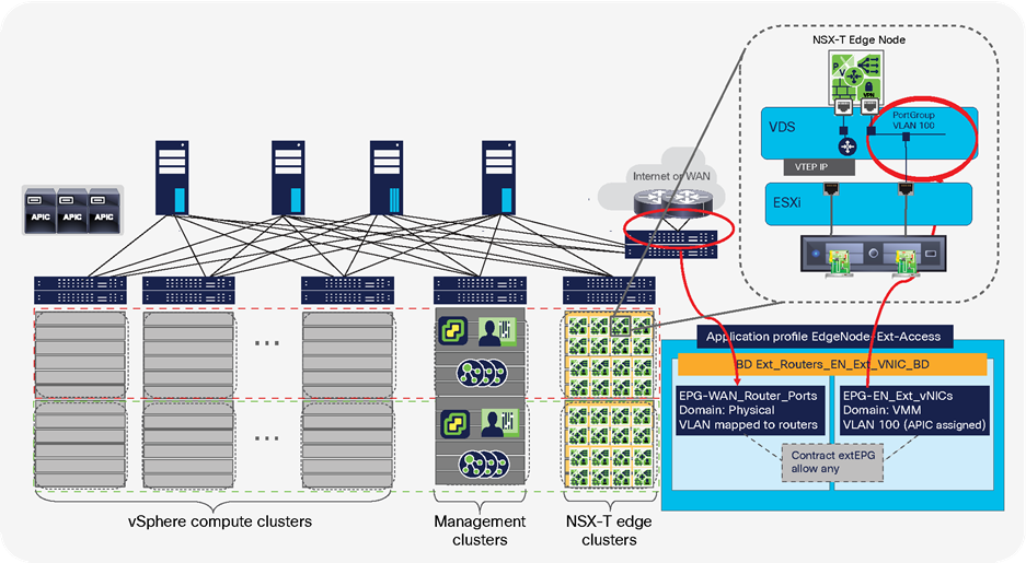
The edge node uplink connects to a dvPortGroups mapped to an EPG where the ACI fabric provides transit at Layer 2 toward the data center WAN routers
It is possible to use a single EPG for connecting the edge node uplink port group and the physical WAN router ports. However, keeping them on separate EPGs facilitates visibility and allows the fabric administrator to leverage Cisco ACI contracts between Tier-0 logical router and WAN routers, offering several benefits:
● The fabric administrator can control the protocols allowed toward the NSX-T overlay, and vice versa, using Cisco ACI contracts.
● If required, the Cisco ACI contracts can drop undesired traffic in hardware, thus preventing the NSX-T Edge Node from having to use compute cycles on traffic that will be dropped anyway.
● The Cisco ACI fabric administrator can use service graphs and automate perimeter NGFWs or intrusion detection and prevention, whether using physical or virtual firewalls.
● The Cisco ACI fabric administrator can use tools such as Switched Port Analyzer (SPAN), Encapsulated Remote Switched Port Analyzer (ERSPAN), or Copy Service to capture in hardware all the traffic to/from specific edge nodes.
In addition, by creating different EPGs for different tenant Tier-0 logical routers on different edge node external vNICs, the NSX-T and fabric administrators benefit from isolation provided within Cisco ACI. For instance, imagine a scenario in which you want to prevent traffic from some networks behind one Tier-0 logical router from reaching another, specific Tier-0 logical router. With NSX-T, the only way to block that traffic is by configuring complex route filtering or firewall policies to isolate tenants, assuming all of the edge nodes are peering through the same logical switch or external uplink port group. With the Cisco ACI EPG model, however, if two edge-node vNICs are on different EPGs, by default those Tier-0 logical routers on the two edge nodes cannot communicate. This separation could also be accomplished by creating a single isolated EPG for all edge-node-external vNICs.
Figure 35 shows an example of this configuration option. A new bridge domain is created to provide a dedicated flooding domain for the Layer-2 path between the edge node and the external routers. Although this domain does not require a subnet to be associated to it, it is always best to configure one and enable routing, so that the fabric handles ARP flooding in the most optimal way and can learn IP addresses of all endpoints to enhance visibility, facilitate troubleshooting, and so forth. In Figure 35 we see two NSX-T tenants, each with dedicated edge node, Tier-0 and Tier-1 logical router sets, as well as redundant edge nodes. The edge node external vNICs are mapped to dedicated Cisco ACI EPGs for each tenant as well, ensuring isolation without requiring complex routing policies. In the basic example, the contract between the edge node vNIC EPG and the router port EPG is a permit-any contract. This contract could be used for more sophisticated filtering, too, or to insert an NGFW using a service graph.
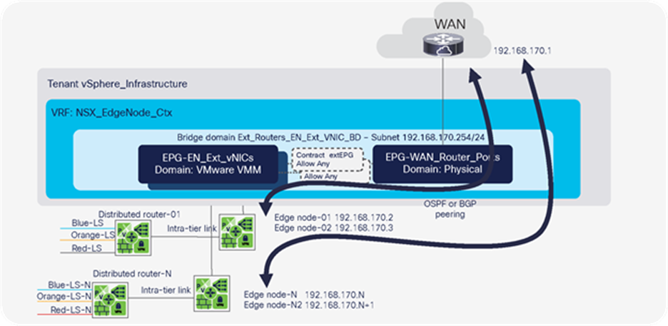
Edge node to WAN over EPG – isolating NSX-T routing domains using different EPGs and contracts
In addition to facilitating tenant isolation, mapping the vNIC external connectivity to an EPG has additional benefits in terms of both automation and mobility. This EPG, like any other, can be defined programmatically and mapped to a VMware VMM domain directly from a cloud platform at the same time the edge node and the Tier-0 logical router are instantiated; for instance, by leveraging the Cisco ACI plug-in for VMware vRealize Automation and Orchestrator. Additionally, the EPG is not tied to a specific leaf or rack. The edge node in virtual machine form factor in this sense is like any other virtual machine connecting to the fabric. If the virtual machine moves, the fabric keeps the virtual machine attached to the right EPG and policy anywhere it roams within the fabric, so the edge clusters are no longer tied to specific racks. Administrators can now create an edge cluster anywhere in the topology and add or remove servers to a cluster as they see fit.
This flexibility contributes to reducing costs, because there is no longer a need to overprovision the edge clusters or to risk under-provisioning them and consequently suffering from additional performance problems on top of those already inherent to using software routing in the data center. Using this approach, the NSX-T Edge Node virtual machine can run in any cluster; there is no need to run clusters dedicated solely to edge-node virtual machines. However, note that it is better to follow VMware recommendations and keep dedicated compute resources for edge nodes because of the difficulty in providing any performance guarantees today for routing functions on a virtual machine. The advantage in any case is that any vSphere cluster can be used for edge node services.
Using Cisco ACI as a Layer-2 fabric to facilitate edge-node peering with the data-center WAN routers provides some very simple and flexible design options. However, traffic between virtual machines in the NSX-T overlay communicating with endpoints in subnets connected to the Cisco ACI fabric needs to wind its way through the Tier-0 logical router on the edge node and then through the WAN routers as well, as illustrated in Figure 36. Note that this is also the case if traffic flows between different NSX-T transport zones.
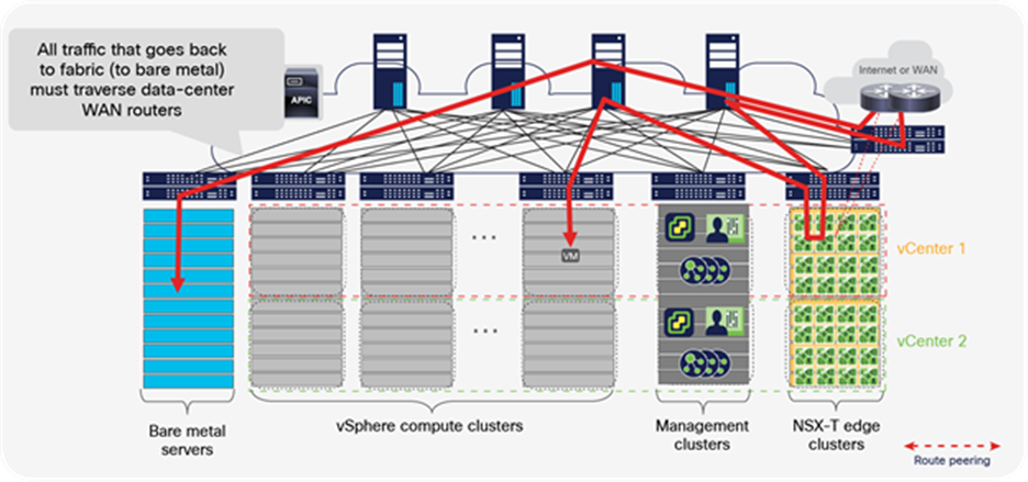
Traffic from a virtual machine in the NSX-T overlay that needs to communicate with an endpoint connected in the ACI fabric will need to traverse the WAN routers if the fabric is Layer-2 only
Tier-0 logical router peering with the fabric using L3Out
In the designs presented earlier in this document, routing is always done from the NSX-T Tier-0 logical router hosted on the edge node to an external data center router where the fabric is used to provide a programmable Layer-2 path between them. If the traffic from the NSX-T overlays is all going to subnets external to the fabric, and not to subnets routed within the fabric, this solution is optimal, given its simplicity.
However, if there is a frequent need for the virtual machines in the NSX-T overlays to communicate with endpoints attached to the fabric, such as bare metal servers, IP storage, or backup systems, routing through the external routers is not efficient.
In these cases, routing can happen directly with the Cisco ACI fabric to obtain more optimal paths, better performance, and lower latency. This method essentially means using L3Outs between the fabric leaf switches and the edge-node virtual machines.
An L3Out interface is a configuration abstraction that enables routing between Cisco ACI fabric nodes and external routers. A Cisco ACI leaf node with an L3Out configuration is commonly called a border leaf. There are various ways to configure L3Outs in Cisco ACI, including using routed interfaces, routed sub-interfaces, Switched Virtual Interfaces (SVIs), and floating SVI. When peering with virtual routers, using SVIs or floating SVI for L3Outs is often the most convenient way, given that the virtual router may not be tied to a specific hypervisor and therefore may be connecting to different leaf switches throughout its lifetime.
The figure below depicts an L3out with SVI in comparison to an L3out with a Floating SVI.
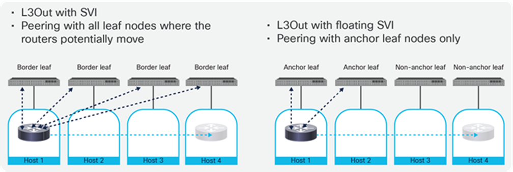
Comparison between an L3Out with SVI and an L3Out with floating SVI
In general, an L3Out with SVI is suitable for the design where virtual routers are running on specific hosts in the cluster under specific leaf nodes instead of across many leaf nodes. This is because an L3Out with SVI has the following characteristics:
● Peering is between virtual routers and all leaf nodes where the virtual routers can potentially move.
● L3Out logical interface paths configuration is required on all leaf ports that are connected to the hosts for the virtual routers because the SVI is deployed only on the specific leaf ports based on the L3Out logical interface paths configuration.
An L3Out with floating SVI is suitable for the design where virtual routers could move across hosts under many different leaf nodes because L3Out with floating SVI has the following characteristics:
● Peering is between virtual routers and specific leaf nodes (anchor leaf nodes) only, though virtual routers can be connected to other leaf nodes (non-anchor leaf nodes).
● L3Out logical interfaces path configuration is not required because the floating SVI is deployed on all leaf ports that have the physical domain for the L3Out that the virtual router is connected.
As of Cisco APIC Release 5.2(3), an L3Out with SVI can expand across up to twelve border leaf switches and an L3Out with floating SVI can expand across up to 6 anchor leaf nodes and 32 non-anchor leaf nodes, enabling a fairly large mobility range for virtual routers peering with Cisco ACI. Please check the latest Verified Scalability Guide for Cisco APIC.
The remaining part of this section explains how to connect and establish peering between NSX-T Edge Nodes and ACI leaf nodes through SVI L3Outs; it is also applicable for connectivity to anchor leaf nodes for an L3Out with floating SVI.
There are multiple ways to connect NSX-T Edge Nodes to Cisco ACI L3Outs. When deciding on the best option, we consider the following design principles:
● Consistency: The design is better if it allows consistent configurations with other ESXi nodes. For instance, VDS configurations should be the same on a ESXi node, whether it runs edge nodes or not.
● Simplicity: The design should involve the least number of configuration elements.
● Redundant: The fabric should provide link and switch node redundancy, providing the fastest convergence possible.
Figure 38 shows a high-level design for connecting Tier-0 logical routers on edge nodes to Cisco ACI SVI L3Outs. The fundamental aspects of this configuration align with the design principles:
● Consistency: Use Link Aggregation Control Protocol (LACP) virtual PortChannels (vPCs) between leaf switches and ESXi hosts. LACP is standards-based and simple. This way the VDS uplink configuration is always the same whether an ESXi host is part of a compute cluster, edge cluster, or converged designs.
● Single edge node uplink port group. This element minimizes configuration, a single SVI L3Out is required on Cisco ACI, and a single uplink is required on the NSX-T edge node.
● Redundant: The edge nodes will peer with all border leaf nodes or anchor leaf nodes in the L3Out (up to twelve for border leaf nodes or six for anchor leaf nodes if needed). Load balancing happens at the LACP level between every ESXi host and the leaf nodes. Link failure convergence does not rely on routing protocols, but rather on LACP. VDS LACP provides sub-second link failure convergence for link failure scenarios between leaf and ESXi host.
This section covers an example with SVI L3Out first (Figures 38 to 41) and then an example with floating SVI L3Out (Figures 42 to 47) using the same IP subnet design.
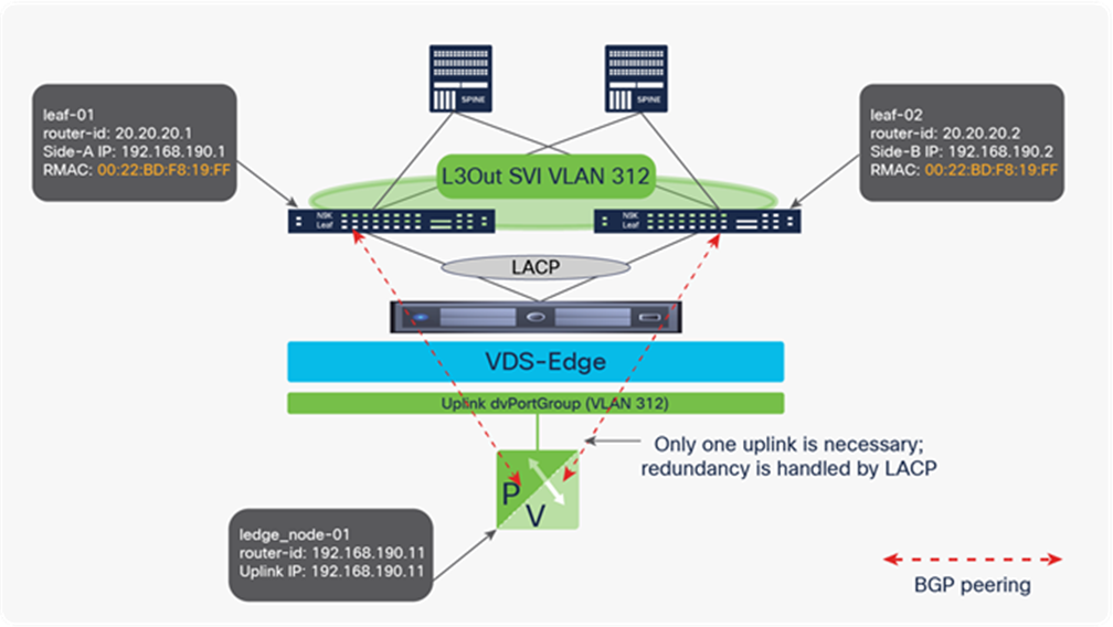
Edge node to Cisco ACI routing design with a single SVI L3Out and single uplink port group, link redundancy achieved with VPC and LACP
Figure 38 highlights the fact that, while the Tier-0 logical router hosted on the edge node will see two routing peers, one per Cisco ACI leaf switch, all prefixes resolve to the same next-hop MAC address corresponding to the SVI L3Out. Traffic is load balanced through the LACP bundle between the ESXi host and the border leaf nodes and is always routed optimally.
To understand this concept better, let’s look at Figure 39, which shows an SVI L3Out using VLAN 312 expanding across two racks (four Cisco ACI leaf switches, assuming redundant leaf switches per rack). The configuration is very simple at the Layer-2 level, since all VDS uplinks and corresponding Cisco ACI VPC policy groups always use the same redundant configuration, based on standard LACP.
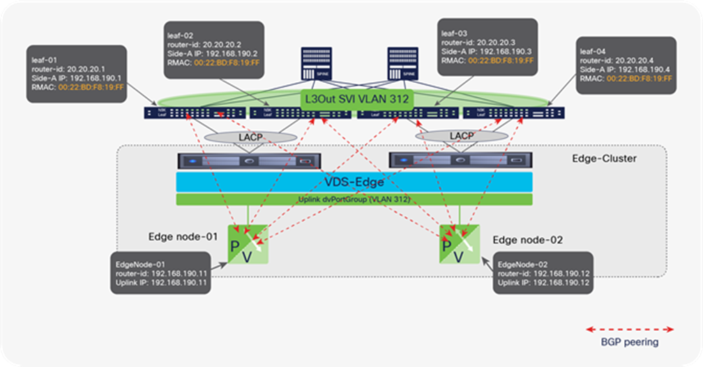
A Cisco ACI SVI L3Out can expand multiple leafs, therefore allowing edge node virtual machines to run route peering even if running on clusters spanning multiple racks
Although the figure refers to BGP, the concept is the same if the subnet is advertised using OSPF. Both Edge node-01 and Edge node-02 will have a single uplink and four BGP peers. Note that this example uses four Cisco ACI leaf switches to illustrate that the edge node can run on a cluster stretching multiple racks, and therefore the administrator could employ vMotion to move an edge nodes across racks.
Figure 40 shows these same Tier-0 routers on the two edge nodes learning subnet 10.80.80.0/24 configured on a Cisco ACI bridge domain. This bridge domain has an association with the L3Out and the subnet is flagged to be advertised as public. Both Edge node-01 and Edge node-02 have four possible routing next-hops for the subnet in question in their routing table, one per Cisco ACI leaf. However, the forwarding table on the Tier-0 router for the next-hops resolves to the same router MAC address for all four routes. Therefore, when any one of the Tier-0 router needs to send traffic toward 10.80.80.0/24, it may choose to send to leaf-01, leaf-02, leaf-03, or leaf-04, but the traffic will always leave the ESXi host having the same VLAN encapsulation (VLAN 312) and the same destination MAC address (00:22:BD:F8:19:FF). When any of the four leaf switches receives packets to that destination MAC address, it performs a route lookup on the packet and routes the packet to the final destination. For instance, Edge node-01 is running on the ESXi host physically connected to leaf-01 and leaf-02. If Edge node-01 sends a packet hitting on the entry pointing to leaf-02, the packet will reach the VDS, where LACP load balances it between the two links between the ESXi host and leaf-01 and leaf-02. Then one of these two switches looks up the packet, because it is sent to the L3Out router MAC address, and forwards the packet to the right destination.
In other words, at all times, all traffic sent from Tier-0 router on Edge node-01 will be using all the links toward leaf-01 and leaf-02; the traffic from the Tier-0 router on Edge node-02 will use the links toward leaf-03 and leaf-04; and all leaf switches will do a single lookup to route all traffic to its final destination. The traffic back from subnet 10.80.80.0/24 will be load balanced across the four leaf switches.
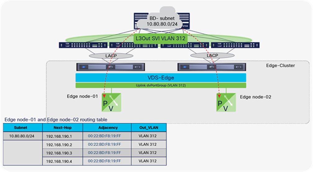
An example of the routing and forwarding table for Edge node-01 and Edge node-02 when peering with a Cisco ACI SVI L3Out
One advantage of this design is shown in Figure 41, where Edge node-01 has moved to the ESXi host connected to leaf-03 and leaf-04, on another rack. Edge node-01 can have a live vMotion for this move, and the routing adjacency will not drop, nor will traffic be impacted. Of course, in the scenario in this figure, traffic from Edge node-01 and Edge node-02 flows only through leaf-03 and leaf-04. Load balancing continues, but now both Tier-0 logical routers on both the edge nodes send and receive traffic through two leaf switches instead of four.
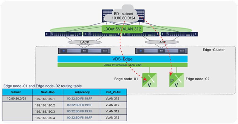
Edge node-01 migrated to another host without impacting the BGP peering status or the routed traffic
Figures 42–47 show the example of floating SVI L3Out, using the same IP subnet design and LACP as the previous example with SVI L3Out. Although Leaf-01 and Leaf-02 are the anchor leaf nodes, and Leaf-03 and Leaf-04 are non-anchor leaf nodes in this example, the use of more than two anchor leaf nodes is possible and can provide even higher redundancy.
In the case of an L3Out with floating SVI, floating SVI IP is deployed on all leaf nodes where the physical interface for the L3Out is deployed or the virtual router is connected, in addition to Side-A and Side-B primary IPs of the anchor leaf nodes. The floating SVI IP is the common IP across anchor leaf nodes and non-anchor leaf nodes.
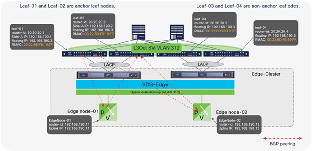
A Cisco ACI floating SVI L3Out can expand multiple leaf nodes without adding peering to all leaf nodes, therefore allowing edge node virtual machines to run on clusters spanning multiple racks
Regardless of whether edge nodes are connected to anchor leaf nodes or to non-anchor leaf nodes, peering is always with anchor leaf nodes only. Figure 43 illustrates an example of the routing and forwarding table for the Edge node-01 and Edge node-02.
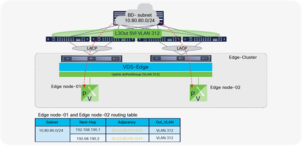
Example of the routing and forwarding table for Edge node-01 and Edge node-02 when peering with a Cisco ACI floating SVI L3Out
One advantage of floating SVI L3Out is that edge nodes can move across ESXi hosts under different leaf nodes without adding peering with all of the leaf nodes, whereas SVI L3Out requires peering with all of the leaf nodes where the edge nodes can potentially be connected. This is especially helpful if the edge nodes move to hosts under different leaf nodes across many racks.
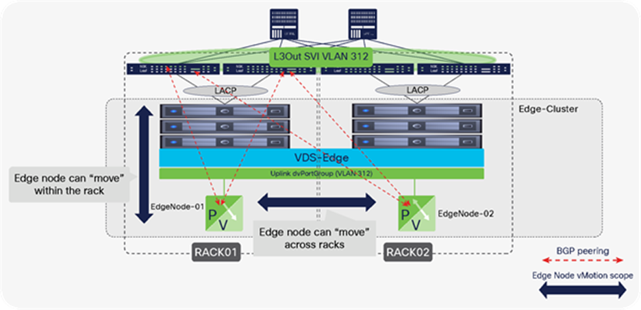
Edge nodes migrated to another host without impacting the BGP peering status or the routed traffic
One consideration of floating SVI L3Out is the traffic flow. Figures 45 and 46 illustrate an example. Even if an edge node is connected under non-anchor leaf nodes, traffic from the edge node to the BD subnet (10.80.80.0/24) is routed by the non-anchor leaf nodes instead of going through the anchor leaf nodes. This is because the destination MAC is 00:22:BD:F8:10:FF, which is the common MAC address across anchor and non-anchor leaf nodes.
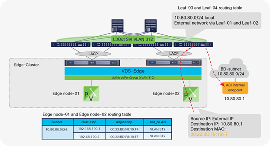
Traffic from the external through edge nodes to a BD subnet (external to internal traffic)
Traffic moving in the opposite direction, from the BD subnet to the external network behind the edge nodes, goes to one of the anchor leaf nodes first by default because the anchor leaf nodes advertise the external subnet to the ACI fabric. Figure 46 illustrates an example. Leaf-03 and Leaf-04 have the external route through Leaf-01 and Leaf-02 TEP IPs.
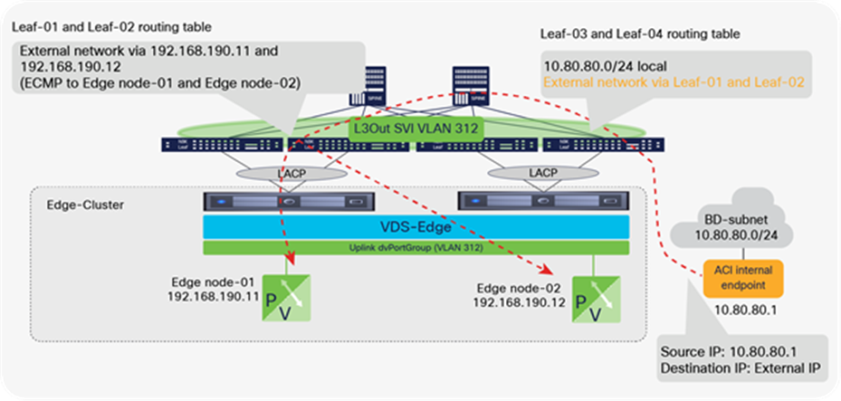
Traffic from a BD subnet to the external through edge nodes (internal to external traffic)
This suboptimal flow can be optimized by enabling the next-hop propagation feature. By enabling the next-hop propagation feature on the L3Out, the next-hop IPs of the external network are propagated to the ACI fabric. Thus, Leaf-03 and Leaf-04 have the external route through the edge nodes’ IPs (instead of the anchor leaf nodes’ TEP IPs) as the next-hops.
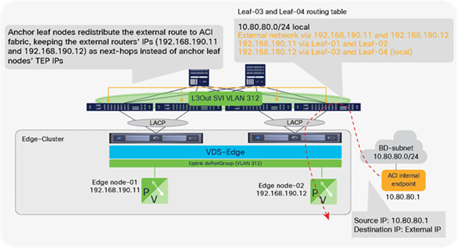
Traffic from a BD subnet to the external through edge nodes (internal to external traffic) with next-hop propagation
For more information on floating SVI L3Out and how to avoid the suboptimal traffic path, please refer to the floating L3Out document.
Using VMware VMM integration also provides benefits in this design scenario. When connecting the edge node toward an L3Out, the VMware VMM domain is not used to configure the edge node uplink dvPortGroups, which must be mapped to an external router domain. But if the VMware VMM domain is configured and monitoring the VDS, the fabric administrator can identify edge node endpoints using the same semantics as the NSX-T administrator.
For instance, Figure 48 shows partial screenshots of the APIC GUI, where the administrator can find an edge node by its name, identify the ESXi host where it is running (and consequently the fabric ports), and monitor the edge node traffic statistics after verifying that the vNICs are connected.
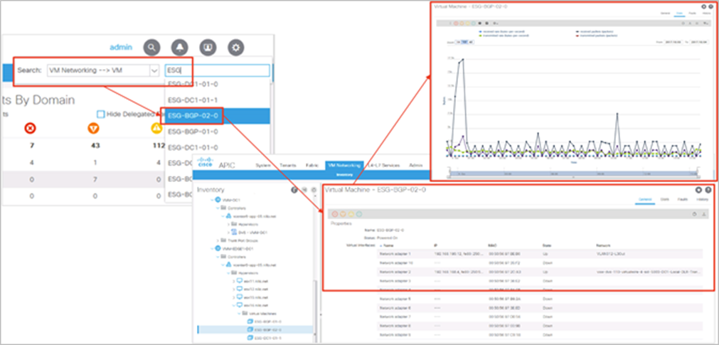
The VMM domain allows the fabric administrator greater visibility and simplifies troubleshooting workflows, in this display showing details of an edge node VM and its reported traffic
Figure 49 illustrates the final result: edge clusters can be designed across multiple racks, and edge-node virtual machines can move within the rack or across racks without impacting routing status or traffic forwarding. Because all ESXi hosts can connect using the same link redundancy mode (VDS), optimal link utilization is achieved while keeping cluster configuration consistency. This facilitates converged designs where edge nodes and user virtual machines share the same clusters.
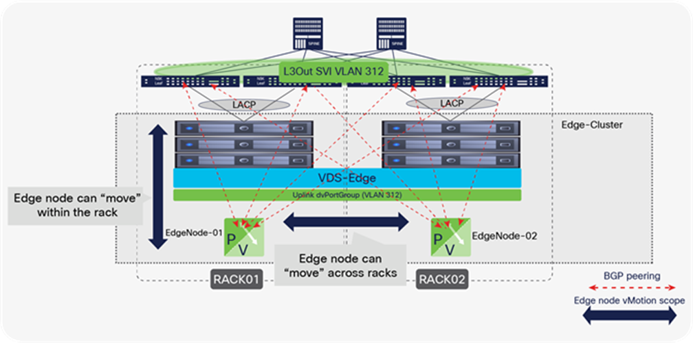
Using SVI L3Outs delivers the fastest possible convergence for link-failure scenarios and enables mobility of edge nodes within and across racks
It is important to understand that the scenario illustrated in Figure 49 does not remove the potential bottleneck that the edge nodes may represent. The distributed logical router load balancing across multiple Edge Nodes is based on source and destination IP addresses, and the Tier-0 logical router on the edge node will in turn use a single virtual CPU (vCPU) for a single flow. The maximum performance per flow will be limited by the capacity of the vCPU, and as a flow is defined by source-destination IP addresses, this configuration can create a bottleneck for any two communicating endpoints. In addition, there is a high probability that multiple IP source-destinations will be sent to the same Tier-0 logical router on the edge node and the same vCPU.
Bridging between logical switches and EPGs
Sometimes virtual machines and bare metal servers are required to be on the same network subnet. When running an NSX-T GENEVE overlay for virtual machines and a VLAN trunk, or untagged access port, for the bare-metal servers, you need to bridge from the GENEVE-encapsulated traffic to VLAN-encapsulated traffic. This bridging allows the virtual machines and bare-metal servers running on the same subnet to communicate with each other.
NSX-T offers this functionality in software through the deployment of NSX-T Layer-2 bridging, allowing virtual machines to be connected at Layer 2 to a physical network through GENEVE VNI-to-VLAN ID mapping. This bridging functionality is configured by attaching the NSX-T Edge bridge profiles to overlay segments and occurs on the active edge node in the edge cluster. There should be at least two edge nodes in the edge cluster on which the Layer-2 bridging is configured. With one edge node as active and the other as standby, ready to take over in case the active edge node fails or has a link down. In Figure 50, the database virtual machine running on the ESXi host is on the same subnet as the bare-metal database server. They communicate at the Layer-2 level. After the traffic leaves the virtual machine, it is encapsulated in GENEVE by the NSX-T VTEP in the hypervisor and sent to the VTEP address of the of the active edge node. That edge node removes the GENEVE header, puts on the appropriate VLAN header that is configured while attaching the edge bridge profile to the GENEVE logical switch and forwards it to the physical leaf switch. The return traffic goes from the bare-metal database server encapsulated in a VLAN header to the Cisco ACI leaf. The leaf forwards the packets to the active edge node, because the MAC address for the database virtual machine is learned on the ports connecting to that host. The active edge node removes the VLAN header, puts the appropriate GENEVE header on the packet, and sends it back to the Cisco ACI leaf, but this time to be sent on the VTEP EPG. The GENEVE packet is delivered to the appropriate ESXi VTEP for forwarding to the virtual machine.
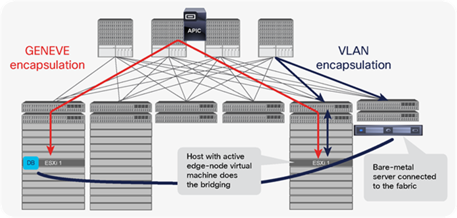
Bare-metal database server and database virtual machine running on the ESXi host share the same subnet
To configure NSX-T layer 2 bridging, an edge bridge profile must be created from the NSX-T Manager GUI. The edge bridge profile must be configured with an edge cluster to utilize for bridging, along with primary and backup edge nodes for bridging, as shown in Figure 51. The edge nodes for bridging can be connected to Cisco ACI through a trunk dvPortGroup or a regular PortGroup, with the uplink of the VDS or vSwitch is connected to Cisco ACI as a physical domain.
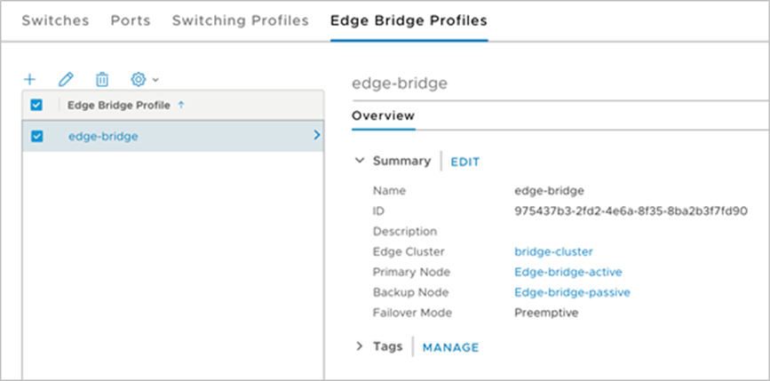
Detail of an edge bridge profile created with primary and backup edge nodes for bridging
Once an edge bridge profile is created, it can be attached to a GENEVE logical switch that needs Layer-2 bridging. The VLAN to be used for the VLAN side of the bridge is configured during this attachment. Once this is set up, the active edge node specified in the edge bridge profile will take up the role of switching the GENEVE VNI header to VLAN headers and the other way around. Figure 52 shows the edge bridge profile attachment to the GENEVE logical switch along with the VLAN configured for the VLAN side of the bridge.
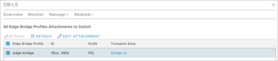
Figure showing edge bridge profile attachment to the GENEVE logical switch and the VLAN configured for bridging
Now we can create an EPG and map the ports to the two edge nodes (as these are the hosts that can do the bridging operations) and any bare-metal servers that need to be on the same subnet using the VLAN tag configured in the edge bridge profile attachment to the GENEVE logical switch using static port bindings.
One EPG is created per bridged VNI-VLAN. Figure 53 shows the two EPGs that are being used for bridging.
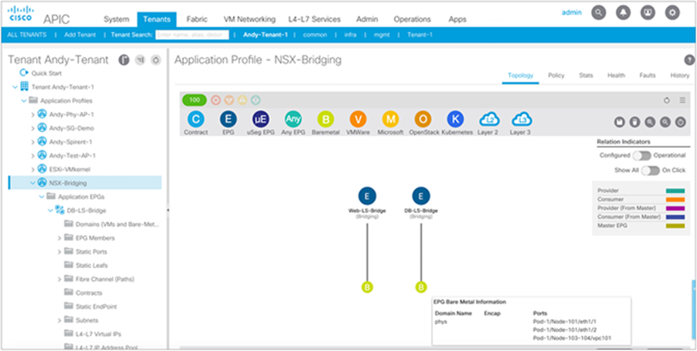
Illustration of two EPGs configured to bridge two specific logical switches in NSX
Figure 54 shows the static path binding configuration for an EPG using VLAN 1001. While it is possible to configure this mapping also at the AEP level, for EPG connected to NSX-T Logical Bridges it is a good practice to ensure static path bindings are used and configured only for the servers running the bridging edge nodes.
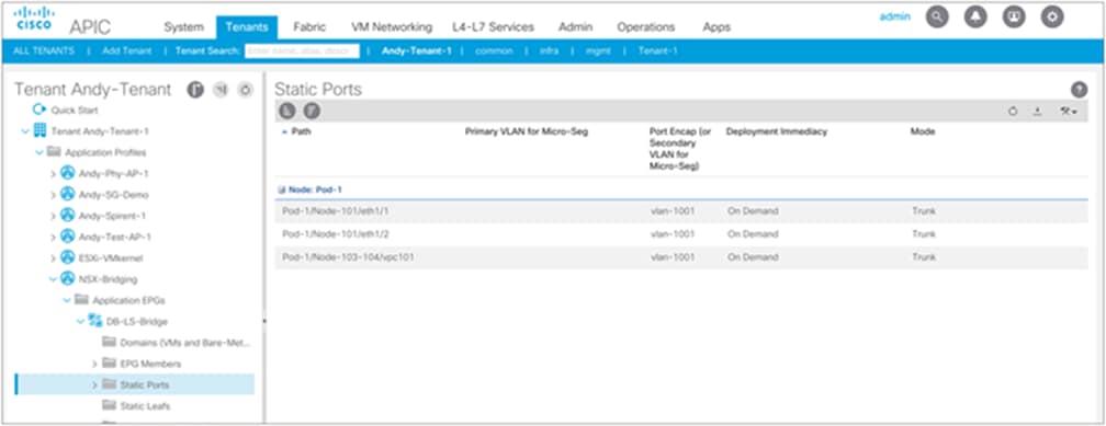
A sample of the configuration of the static path binding. Each path represents ports connected to the distributed logical router bridge ESXi hosts
This paper has discussed various options to design a vSphere infrastructure that uses VMware NSX-T with a Cisco ACI fabric. It explored two main options:
● Option 1 (Cisco Recommended): Using Cisco ACI integrated overlay for network virtualization combined with NSX-T network services, distributed firewall, and security APIs.
● Option 2: Using NSX-T network virtualization with Cisco ACI fabric as underlay.
Customers using NSX-T for vSphere will realize many benefits when using a Cisco ACI fabric:
● Cisco ACI offers industry-leading performance on a cost-effective 40/100-Gbps network fabric leveraging Cisco cloud-scale innovations such as smart buffering or dynamic packet prioritization to enhance application performance.
● APIC centralizes the management and policy plane of the data center fabric, thus providing automated provisioning and visibility into vSphere infrastructure traffic, such as iSCSI, NFS, vMotion, fault tolerance, and securing management access.
● Cisco ACI offers a simplified view of the health of the fabric on a per-tenant and per-application basis, underpinned by granular telemetry information that allows for faster identification and resolution of problems. This provides immediate benefits for general vSphere infrastructure and NSX-T alike.
● Cisco ACI can contribute to reducing the complexity of the routing design in NSX-T in a number of ways: it can help reduce tiers of Tier-0 logical routers and associated edge nodes, automate insertion of perimeter firewalls in front of the Tier-0 logical router tiers, and contribute to eliminating the Tier-0 logical routers and the edge node tiers altogether by allowing administrators to leverage the integrated overlay model intrinsic to Cisco ACI.
● Cisco ACI allows customers to standardize and simplify all server networking by leveraging standard protocols such as LACP for all server redundancy. Cisco ACI allows running dynamic routing over VPC, and, because L3Out interfaces expand across multiple leaf switches, they enable designs with stretched edge clusters.
● The Cisco ACI VMM integration enables fabric administrators to find edge-node virtual machines by name, identify their connectivity settings, monitor traffic statistics, and more—from a single tool.
● Customers can use NSX-T for its security features while leveraging Cisco ACI network virtualization capabilities, completely eliminating the need for logical routers and edge-node virtual machines. This approach enables customers to use all NSX-T security and load-balancing features and partners while lowering the cost of deploying NSX-T and eliminating bottlenecks and complexity.
● Finally, because Cisco ACI provides integrated overlays along with a contract model that can be used to implement zero-trust designs with microsegmentation, organizations can consider whether, once Cisco ACI has been adopted, they need to continue running NSX-T.
For running VMware vSphere and NSX-T with Cisco ACI® fabric, the following configurations are recommended:
● Design option 1: Running VMware NSX-T security and virtual services using a Cisco ACI–integrated overlay for network virtualization is recommended.
● For physical connectivity from the vSphere ESXi host to Cisco ACI fabric, the use of active/active redundancy options such as MAC pinning and LACP to utilize the bandwidth across multiple links is recommended.
● Utilize an Attachable Entity Profile (AEP) for a group of similar servers, such as one AEP per vSphere cluster.
● For tenant design, it’s recommended to have a separate tenant for vSphere infrastructure traffic and separate bridge domains for different vSphere infrastructure traffic types such as management, storage, and vMotion.
● Aggregate the infrastructure endpoints on per cluster level. Table 2 in the document summarizes the recommended settings of bridge domains and EPGs.
● Implement a zero-trust approach to vSphere infrastructure traffic through contracts and allow only required ports and protocols to communicate.
● When using NSX-T for distributed firewall service, instead of completely disabling Cisco ACI policy enforcement inside the VRF, placing EPGs mapped to the VMware SDN VMM domain in a preferred group is recommended.
● If using design option 2, use the Cisco ACI VMware VMM domain for managing and monitoring the VDS for vSphere infrastructure traffic.
Do you need NSX-T when running a Cisco ACI fabric?
Cisco ACI was designed to offer a fully integrated overlay and underlay solution for virtual and physical endpoints with distributed security. As a result, for most customers, Cisco ACI offers all of the security and network virtualization functions required for a VMware vSphere environment, and therefore makes the deployment of VMware NSX-T unnecessary.
When working with vSphere environments, Cisco ACI supports using the native vSphere Distributed Switch. Cisco ACI programs the VDS by means of the vCenter northbound API. The vSphere VDS and vCenter API allow programming of networking constructs such as port groups, VLAN, isolated private VLANs, uplink policies, and the like.
Customers deploying vSphere on Cisco ACI fabrics get many benefits out of the box:
● Workload mobility: Cisco ACI allows extending networks across any number of vSphere clusters within single or multiple data centers. Solutions such as Cisco ACI Multi-Pod and Cisco ACI Multi-Site allow customers to easily implement vSphere Metro Storage Clusters or even multiple-vCenter deployments and seamlessly migrate workloads anywhere in the infrastructure.
● Simplify Site Recovery Manager deployments: Cisco ACI makes it extremely simple to extend Layer 2 and Layer 3 networks across multiple sites, including virtual machine–traffic networks and infrastructure networks serving vMotion, IP storage, and fault tolerance.
● Microsegmentation: Cisco ACI offers microsegmentation and workload isolation capabilities on the native VDS. Cisco ACI also extends microsegmentation support beyond vSphere clusters into other hypervisors and bare metal servers.
● Layer 4–7 automation: Cisco ACI includes integration with a broad range of Layer 4–7 device partners and can provide policy-based redirection to both physical and virtual service devices.
Out-of-the-box integration with leading cloud-management platforms, including VMware vRealize Automation. By leveraging the Cisco ACI vRealize Plug-in customers can use a large number of pre-defined workflows to automate many Cisco ACI fabric configurations.
For organizational reasons, sometimes customers choose to use NSX-T with Cisco ACI fabrics. For instance, they may be deploying turnkey solutions that use NSX-T as a component, or they may be interested in specific security partners of the NSX-T ecosystem.
Nonetheless, considering the rich capabilities included in Cisco ACI, many customers find that deploying Cisco ACI meets their requirements without adding a second network overlay, thus eliminating the additional cost of VMware NSX-T licenses and the hardware required to run all the associated components.