Cisco ACI Contract Guide White Paper
Available Languages
Bias-Free Language
The documentation set for this product strives to use bias-free language. For the purposes of this documentation set, bias-free is defined as language that does not imply discrimination based on age, disability, gender, racial identity, ethnic identity, sexual orientation, socioeconomic status, and intersectionality. Exceptions may be present in the documentation due to language that is hardcoded in the user interfaces of the product software, language used based on RFP documentation, or language that is used by a referenced third-party product. Learn more about how Cisco is using Inclusive Language.
This document describes Cisco® Application Centric Infrastructure (Cisco ACI®) contract behavior, configuration options, and deployment considerations.
This document assumes that the reader has a basic knowledge of Cisco ACI technology. For more information, see the Cisco ACI white papers available at Cisco.com: https://www.cisco.com/c/en/us/solutions/data-center-virtualization/application-centric-infrastructure/white-paper-listing.html.
This document uses the following terms, with which you will need to be familiar:
● BD: bridge domain
● EPG: endpoint group
● EP: endpoint residing in an ACI fabric
● L3Out: Layer 3 Out or external routed network
● L3Out EPG: subnet-based EPG in L3Out
● VRF: Virtual Routing and Forwarding
● Border leaf: ACI leaf where L3Out is deployed
● EX leaf: 2nd generation Cisco Nexus 9300 series switch ending with -EX, such as Nexus 93180YC-EX
● FX leaf: 2nd generation Cisco Nexus 9300 series switch ending with -FX, such as Nexus 93180YC-FX
The document covers features up to Cisco ACI Release 6.0. It discusses how contracts work, and design considerations and deployment options regarding contracts. This document uses EPGs mainly as part of explanation, but contract related features and behaviors shall be applicable to both EPGs and ESGs unless otherwise indicated. Table 1 lists configuration options that are often discussed during design conversations. Detailed use cases and explanations are presented later in this document.
Table 1. Contract-related features
| Feature/option name |
Configuration location* |
Cisco ACI release when first introduced |
Behavior |
Consideration |
| Benefit |
||||
| Tenant > Networking > VRFs > VRF_name > EPG Collection for VRF |
1.0 |
Collection of EPGs in a VRF |
|
|
| Tenant > Networking > VRFs > VRF_name |
1.0 |
Permit all traffic within VRF |
Contract can’t be enforced on the VRF at all. |
|
| Simplify configuration. Reduce TCAM resource consumption. |
||||
| Tenant > Networking > VRFs > VRF_name Tenant > Application Profiles > Application_Profile_name > Application EPGs > EPG_name |
2.2 |
Permit all traffic between EPGs in preferred group |
This might not contribute to reducing TCAM resource consumption. |
|
| Simplify configuration. Contract can be still enforced on the VRF. |
||||
| Tenant > Contracts > Contract_name > Subject_name > L4-L7 Service Graph |
2.0 |
Redirect traffic based on contract |
Service graph is mandatory when using PBR. |
|
| Tenant > Application Profiles > Application_Profile_name > Application EPGs > EPG_name |
1.2(2g) |
Deny communication between endpoints in the EPG |
This denies all communication in the EPG. PVLAN (Private VLAN) is used behind the scene. |
|
| Tenant > Application Profiles > Application_Profile_name > Application EPGs > EPG_name > Contracts |
3.0 |
Enforce contract between endpoints in the EPG |
PVLAN (Private VLAN) is used behind the scene. |
|
| Granular security enforcement within EPG |
||||
| Tenant > Networking >L3Outs > L3Out_name > External EPGs > L3Out_EPG_name |
5.2 |
Deny communication within the L3Out EPG |
How trarffic reaches the ACL leaf for intra Ext-EPG enforcement is outside of ACI’s control. |
|
| Enforce security within L3Out EPG |
||||
| Tenant > Networking >L3Outs > L3Out_name > External EPGs > L3Out_EPG_name > Policy > Contracts |
5.2 |
Enforce contract within the L3Out EPG |
L3Out EPG with 0.0.0.0/0 or 0::0 can’t use intra Ext-EPG contract. Inplicit deny rule is not automatically added. Intra Ext-EPG isolation needs to be enabled to deny traffic if needed. |
|
| Granular security enforcement within L3Out EPG |
||||
| Tenant > Application Profiles > Application_Profile_name > Application EPGs > EPG_name > EPG Contract Master |
2.3 |
Inherit contract relationship configuration of master EPG |
This doesn’t contribute to reduce TCAM resource consumption. |
|
| Simplify configuration |
||||
| Tenant > Contracts > Contract_name > Subject_name > filter_name in Filters |
3.2: Bidirectional rule compression 4.0: Policy table compression |
Bidirectional subjects take one entry only in TCAM (3.2). Reuse filter (4.0) |
Bidirectional rule compression requires EX leaf or later. Policy table compression requires FX leaf or later. Statistics information is missing if compression is enabled. |
|
| Reduce TCAM resource consumption |
||||
| Tenant > Contracts > Contract_name > Subject_name > filter_name in Filters |
1.0: Deny logging 2.0: Permit logging |
Enable logging for permitted and denied packet and flow |
Packet logging has rate limit and requires EX or later. (500 pps for deny, 300 pps for permit) |
|
| Take logs for important permit traffic |
||||
| Tenant > Contracts > Contract_name > Subject_name > filter_name in Filters |
3.2 |
Explicitly deny traffic based on contract |
|
|
Contracts overview
The fundamental security architecture of the Cisco ACI solution follows an allow-list model where we explicitly define what traffic should be permitted. A contract is a policy construct used to define communication between EPGs. Without a contract between EPGs, no unicast communication is possible between those EPGs unless the VRF is configured in “unenforced” mode or those EPGs are in a preferred group. A contract is not required to allow communication between endpoints in the same EPG (although communication can be prevented with intra-EPG isolation or intra-EPG contract).
Note: Contracts are applied on unicast traffic only. BUM traffic such as Broadcast, Unknown unicast and Multicast Protocols, and protocols listed in this FAQ, are implicitly permitted.
The figure below shows the relationship between EPGs and contracts.
EPGs and contracts
An EPG provides or consumes contracts. For instance, the App EPG in the example in Figure 1 provides a contract that the Web consumes, and consumes a contract that the DB EPG provides.
An endpoint can belong to one EPG. Physical, virtual, and container endpoints can coexist in the same EPG. How to define which EPG an endpoint belongs to is based on the EPG type, as described below:
● L3Out EPG based on the IP subnet (longest prefix match)
● EPG that is based on the leaf interface and VLAN ID, or the leaf interface and VXLAN
◦ uSeg EPG (also called micro EPG) that is based on IP, MAC VM attributes, such as VM name, or a combination of IP, MAC, and those attributes
Defining which side is the provider and which one is the consumer of a given contract allows establishing a direction of the contract where to apply ACL (Access Control List) filtering; for instance, if the Web EPG is a consumer of the contract provided by the App EPG, you may want to define a filter that allows HTTP port 80 as a destination in the consumer-to-provider direction and as a source in the provider-to-consumer direction. In the case of a traditional network, those two filters for both directions are separate ACLs. In the case of an ACI fabric, when a contract with an HTTP filter: source port of “Any,” and a destination port of “80,” is configured between Web EPG and App EPG, two filters (one per direction) are deployed in Cisco ACI by default, as shown in Figure 2.

Web as consumer and App as provider
If, instead, you had defined Web EPG as the provider and App EPG as the consumer of the contract, you would define the same filters in the opposite direction; that is, you would allow HTTP port 80 as the source in the consumer-to-provider direction and as the destination in the provider-to-consumer direction.
App as consumer and Web as provider
In the most common designs, you do not need to define more than one contract between any EPG pair. If there is a need to add more filtering rules to the same EPG pair, this can be achieved by adding more subjects to the same contract.
Note: In case of Multi-Site deployment, Cisco Multi-Site Orchestrator (MSO) creates one contract for each subject.
Subjects and filters
A subject is a construct contained within a contract and references a filter. A contract contains one or more subjects and a subject contains one or more filters. A filter contains one of more filter entries. A filter entry is a rule specifying fields such as the TCP port and protocol type. Figure 4 provides an example.
Contract, subject, filter, and filter entries
Figure 5 shows how contracts, subjects, and filters are configured.
The following configurations are performed per filter entry level: whether to permit or deny traffic.
The following configurations are performed per subject level: whether to apply an L4-L7 Service Graph and which QoS priority to assign to the traffic.
Contracts, subjects, and filters
Figure 6 shows how filters and filter entries are configured. A filter is collection of filter entries: The configurations related to the match criteria for the traffic are defined in a filter entry.
Filters and filter entries
The configuration options at the subject level and the ones defined as a filter entry will be explained later in this document. Unless the configuration options are specifically mentioned, examples and behaviors explained in this document are based on the default configuration:
● Apply Both Directions: The filter protocol and the source and destination ports are deployed exactly as defined for both consumer-to-provider and provider-to-consumer directions.
● Reverse Filter ports: This option should be used always when Apply Both Directions is enabled. The filter protocol and the source and destination ports are deployed exactly as defined for the consumer-to-provider direction, and with source and destination ports reversed for the provider-to-consumer direction. Figure 2 illustrates the use of Apply Both Directions in conjunction with reverse filter ports (which is the default configuration).
● Permit Action: Traffic that is matched with filter entries is permitted between EPGs.
How a contract works for intra-VRF traffic
This section covers how a contract works if the consumer and provider EPGs are in the same VRF.
Overview
Figure 7 illustrates an example of an Intra-VRF contract. Consumer and provider EPGs are in the same VRF. Consumer and provider EPGs can be in the same or in a different BD. The CLI outputs in this section are based on this topology.
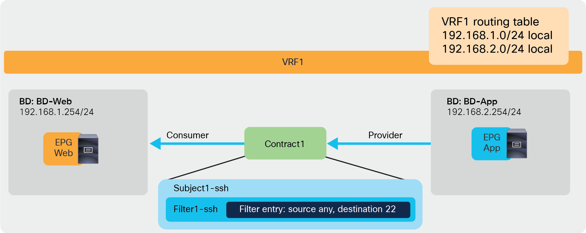
Intra-VRF contract example
Configuration steps
Some objects must be created on an APIC before contract configuration. This document doesn’t cover how to create tenants, VRFs, BDs, EPGs, and L3Out. The assumption is that the items below are already configured:
● Initial setup of the ACI fabric (such as discovering APIC, leaf, and spine)
● Fabric access policies and domains
● Tenant, VRFs, BDs, EPG, and L3Out
For more information on how to perform an initial setup of an ACI fabric, please refer to the “Setting Up a Cisco ACI Fabric: Initial Deployment Cookbook”: https://www.cisco.com/c/en/us/td/docs/switches/datacenter/aci/apic/white_papers/Cisco-ACI-Initial-Deployment-Cookbook.html
The contract configuration steps are as follows:
1. Create a filter.
2. Create a contract.
3. Add the contract to the consumer and provider EPGs.
The following subsections provide the steps for these configurations.
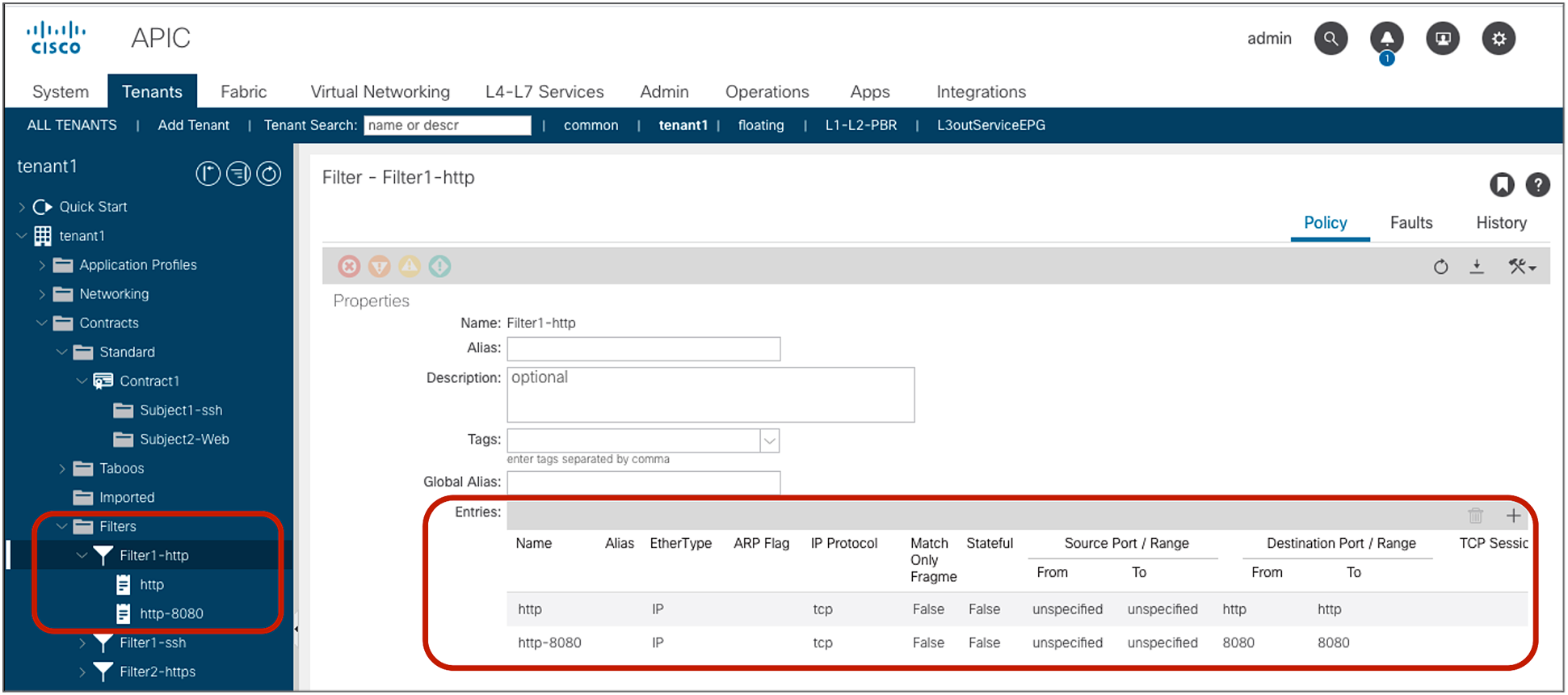
Create a filter
A filter contains one or more filter entries that specify the matching rule. The filter configuration is located at Tenant > Contracts > Filters. The example below (Figure 8) defines the rule to allow TCP traffic destined to port 22 from any source port. Source port and destination port ranges can be specified by using “From” for the first number and “To” for the last port number.
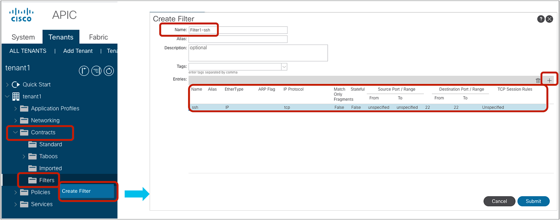
Create a filter
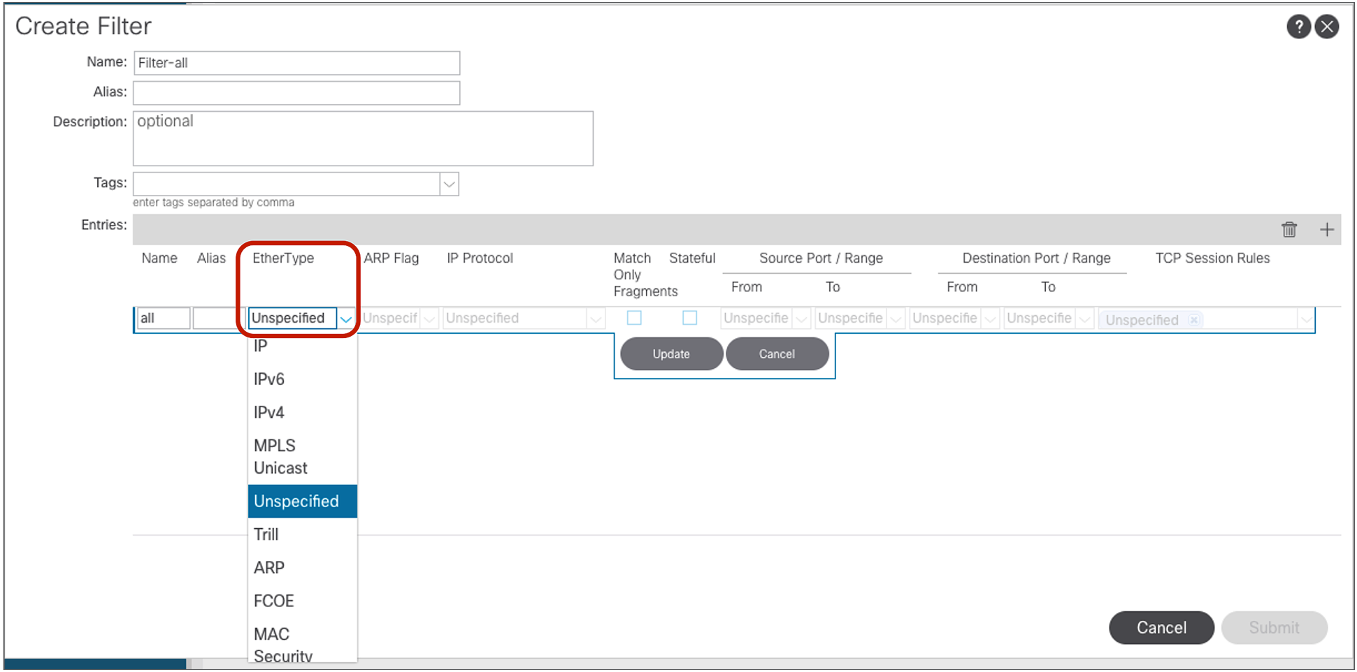
Note: “Unspecified” means “any.”
The filter entry in the following configuration example (Figure 9) uses “Unspecified.” If EtherType is “Unspecified,” other options can’t be entered because this filter matches all EtherTypes.
Filter configuration example: match all
Figure 10 illustrates how to configure a filter to match all IPv4 TCP traffic. Because of this, the filter defines both source and destination ports as unspecified.
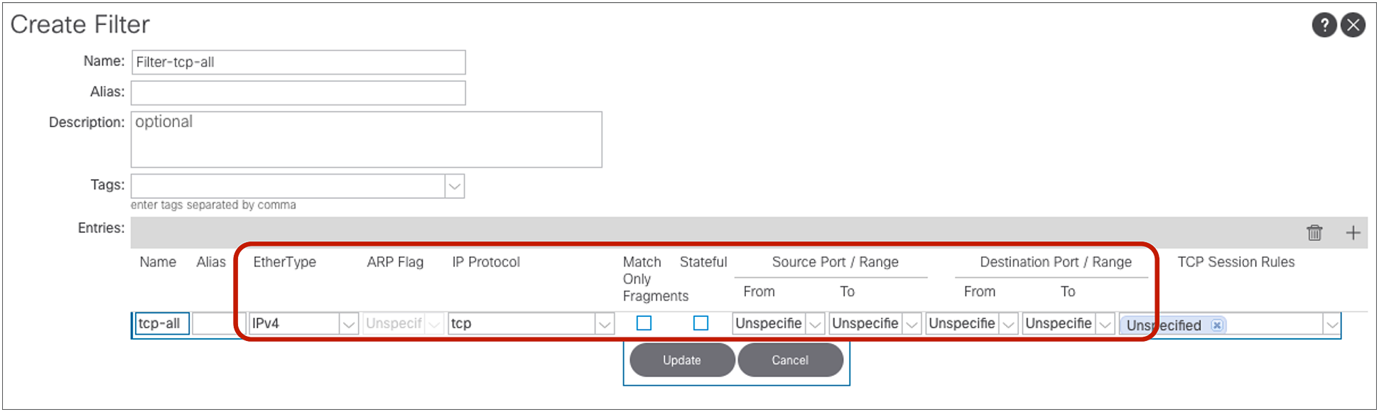
Filter configuration example: IPv4 TCP all
Cisco ACI provides predefined filters in the common tenant, such as default (permit-all) and ICMP (Internet Control Message Protocol), which can be used from any tenant.
Create a contract
Location is at Tenant > Contracts > Standard.

Create a contract
Add the contract to EPGs
The EPG location is at Tenant > Application Profiles > Application_Profile_name > Application EPGs > Consumer_EPG_name or Provider_EPG_name. An EPG can be the consumer or provider of multiple contracts. A contract can have multiple consumer and provider EPGs.

Consume or provide a contract
Policy programming
Once the contract is associated with a consumer and a provider EPG, the leaf has the security policy programmed in the TCAM (Ternary Content Addressable Memory) if the consumer or provider EPG is deployed on the leaf. The conditions of EPG deployment are explained in the “Resolution and deployment immediacy” section.
Note: Unless it’s specifically mentioned, the examples with output of the CLI commands in this document use a leaf that has deployed both consumer and provider EPGs.
The security policies programmed on leaf nodes are called zoning rules. Zoning rules are per VRF, and each entry defines an action based on the source EPG, the destination EPG, and filter matching. Each EPG has a unique ID called a class ID or pcTag. Each VRF has a unique ID called a VRF scope. Both the EPG class ID and the VRF scope are dynamically assigned by the system. Unless troubleshooting or verification is required, users don’t have to know the class IDs.
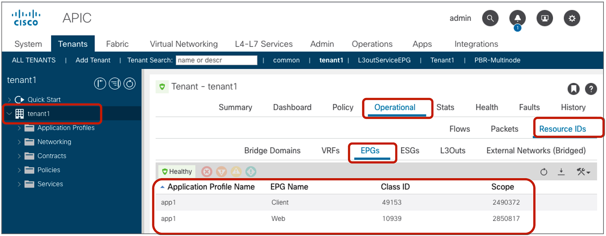
The EPG class ID and the VRF scope can be found at Tenant > Operational > Resource IDs > EPGs.

EPG class ID and VRF scope
show zoning-rule
The policy-cam (TCAM) programming on a leaf can be verified by using the command: “show zoning-rule scope VRF_scope”, as shown below:
Pod1-Leaf1# show zoning-rule scope 2850817
+---------+--------+--------+----------+----------------+---------+---------+-------------------+----------+----------------------+
| Rule ID | SrcEPG | DstEPG | FilterID | Dir | operSt | Scope | Name | Action | Priority |
+---------+--------+--------+----------+----------------+---------+---------+-------------------+----------+----------------------+
| 4220 | 0 | 16386 | implicit | uni-dir | enabled | 2850817 | | permit | any_dest_any(16) |
| 4250 | 0 | 0 | implicit | uni-dir | enabled | 2850817 | | deny,log | any_any_any(21) |
| 4208 | 0 | 0 | implarp | uni-dir | enabled | 2850817 | | permit | any_any_filter(17) |
| 4249 | 0 | 15 | implicit | uni-dir | enabled | 2850817 | | deny,log | any_vrf_any_deny(22) |
| 4248 | 0 | 32773 | implicit | uni-dir | enabled | 2850817 | | permit | any_dest_any(16) |
| 4247 | 32775 | 32774 | 67 | bi-dir | enabled | 2850817 | tenant1:Contract1 | permit | fully_qual(7) |
| 4246 | 32774 | 32775 | 68 | uni-dir-ignore | enabled | 2850817 | tenant1:Contract1 | permit | fully_qual(7) |
+---------+--------+--------+----------+----------------+---------+---------+-------------------+----------+----------------------+
In this example, red-highlighted Rule ID 4247 and 4246 are created by Contract1 to permit traffic between Web EPG (class ID 32775) and App EPG (class ID 32774) in tenant1 VRF1 (scope 2850817). Other entries are implicit rules created by the system. This will be explained in the next subsection “Implicit rules”.
● Rule ID: the ID of the rule entry. This has no real significance other than to act as a unique identifier.
● Src EPG: a unique class ID (pcTag) per VRF of the source EPG
● Dst EPG: a unique class ID (pcTag) per VRF of the destination EPG
● FilterID: the ID of the filter associated with the policy-cam rule. The filter contains the protocol information and L4 ports that the rule will match against.
● Dir: the directionality of the zoning rule:
◦ uni-dir: This is a unidirectional zoning rule.
◦ bi-dir and uni-dir-ignore: These are also unidirectional zoning rules, but bi-dir and uni-dir-ignore rule pair are combined into one hardware entry if policy compression is enabled.
● OperSt: the operating state of the rule. It should be “enabled.” If the rule is not programmed properly in the hardware, it becomes disabled.
● Scope: a unique ID of the VRF that the rule will match against
● Name: the name of the contract that resulted in that entry being programmed
● Action: what the leaf will do when it matches that entry. It includes: [Drop, Permit, Log, Redirect].
● Priority: the order in which the zoning rules will be validated for action, given a matching scope, SrcEPG, DstEPG, and Filter Entries. The lower the number, the higher the priority.
Note: Zoning-rule entries are used to perform stateless filtering. If you need Cisco ACI to perform stateful filtering, such as a firewall, you need also to deploy the Application Virtual Edge on the server.
show zoning-filter
Each individual filter ID in the zoning-rule table can be verified by “show zoning-filter filter_id.”
Pod1-Leaf1# show zoning-filter filter 67
+----------+------+--------+-------------+------+-------------+----------+-------------+-------------+-----------+---------+-------+-------------+-------------+----------+
| FilterId | Name | EtherT | ArpOpc | Prot | ApplyToFrag | Stateful | SFromPort | SToPort | DFromPort | DToPort | Prio | Icmpv4T | Icmpv6T | TcpRules |
+----------+------+--------+-------------+------+-------------+----------+-------------+-------------+-----------+---------+-------+-------------+-------------+----------+
| 67 | 67_0 | ip | unspecified | tcp | no | no | unspecified | unspecified | 22 | 22 | dport | unspecified | unspecified | |
+----------+------+--------+-------------+------+-------------+----------+-------------+-------------+-----------+---------+-------+-------------+-------------+----------+
Pod1-Leaf1# show zoning-filter filter 68
+----------+------+--------+-------------+------+-------------+----------+-----------+---------+-------------+-------------+-------+-------------+-------------+----------+
| FilterId | Name | EtherT | ArpOpc | Prot | ApplyToFrag | Stateful | SFromPort | SToPort | DFromPort | DToPort | Prio | Icmpv4T | Icmpv6T | TcpRules |
+----------+------+--------+-------------+------+-------------+----------+-----------+---------+-------------+-------------+-------+-------------+-------------+----------+
| 68 | 68_0 | ip | unspecified | tcp | no | no | 22 | 22 | unspecified | unspecified | sport | unspecified | unspecified | |
+----------+------+--------+-------------+------+-------------+----------+-----------+---------+-------------+-------------+-------+-------------+-------------+----------+
The filter 67 is used to match traffic with any source port to destination port 22; the filter 68 is for the opposite direction. The figure below illustrates the effect on traffic of the zoning rules from the previous example.

Intra-VRF contract example
Implicit rules are rules that are not defined by the administrator but are programmed by Cisco ACI. ACI always creates implicit rules unless the VRF is configured in unenforced mode.
Pod1-Leaf1# show zoning-rule scope 2850817
+---------+--------+--------+----------+----------------+---------+---------+-------------------+----------+----------------------+
| Rule ID | SrcEPG | DstEPG | FilterID | Dir | operSt | Scope | Name | Action | Priority |
+---------+--------+--------+----------+----------------+---------+---------+-------------------+----------+----------------------+
| 4220 | 0 | 16386 | implicit | uni-dir | enabled | 2850817 | | permit | any_dest_any(16) |
| 4250 | 0 | 0 | implicit | uni-dir | enabled | 2850817 | | deny,log | any_any_any(21) |
| 4208 | 0 | 0 | implarp | uni-dir | enabled | 2850817 | | permit | any_any_filter(17) |
| 4249 | 0 | 15 | implicit | uni-dir | enabled | 2850817 | | deny,log | any_vrf_any_deny(22) |
| 4248 | 0 | 32773 | implicit | uni-dir | enabled | 2850817 | | permit | any_dest_any(16) |
| 4247 | 32775 | 32774 | 67 | bi-dir | enabled | 2850817 | tenant1:Contract1 | permit | fully_qual(7) |
| 4246 | 32774 | 32775 | 68 | uni-dir-ignore | enabled | 2850817 | tenant1:Contract1 | permit | fully_qual(7) |
+---------+--------+--------+----------+----------------+---------+---------+-------------------+----------+----------------------+
In the example above, the red-highlighted Rule IDs are implicit rules. Table 2, below, explains these implicit rules.
● Deny any to any: to deny all inter-EPG communication in the VRF. This is the implicit deny, which takes effect when there are no explicit contracts between EPGs.
● Permit ARP unicast: to permit all ARP unicast communication between EPGs
● L3Out: to deny any to 0.0.0.0/0 L3Out EPG traffic unless a contract is configured. This is used only when preferred group is enabled.
● Permit Any to BD where the EPG resides: to permit and flood unknown unicast traffic on the ingress leaf and enforce the policy on the egress leaf
Table 2. Implicit rules
| When it’s used |
Source class id |
Destination class id |
Filter ID |
Action |
Explanation |
Priority* |
| Deny any to any |
0 |
0 |
Implicit (unspecified) |
Deny |
Deny any-to-any traffic |
21 |
| Permit ARP unicast |
0 |
0 |
Implarp (EtherType: ARP) |
Permit |
Permit any-to-any ARP unicast traffic |
17 |
| Permit unknown unicast traffic |
0 |
BD class ID** |
Implicit (unspecified) |
Permit |
Permit and flood the unknown unicast traffic on ingress leaf and enforce the policy on egress leaf |
16 |
| L3Out EPG with 0.0.0.0/0 subnet |
0 |
15*** |
Implicit (unspecified) |
Deny |
It is not used, and is not even programmed on hardware, unless preferred group is enabled. |
22 |
In order to understand Table 2, you need to consider that the contract action is enforced based on the priorities of the entries. A lower number (*) has a higher priority. Please see the “Contract priorities” section for more details. Class ID 0 means “any” EPG in the VRF (it may help to think of class ID 0 as the “any” in classic access-lists), and class ID 15 (***) is reserved for 0.0.0.0/0 L3Out EPG as a destination. Please see L3Out EPG with 0.0.0.0/0 subnet for more details.
The BD class ID (**) is an identifier for the traffic destined to the entire bridge domain, similar to the identifier for the VRF or the identifier of the EPG. The BD class ID information can be found at Tenant > Operational > Resource IDs > Bridge Domains. In Figure 15, BD-Web where Web EPG resides has BD class ID 16386 and BD-App where App EPG resides has a BD class ID 32773.

BD class ID
A comprehensive list of the implicit rules used by Cisco ACI is available in the “FAQ” section.
Note for advanced readers: Cisco ACI carries traffic encapsulated in VXLAN. The VXLAN headers include information about whether ACI has already performed the policy enforcement on the packet or not. This is done via the “policy applied bit.” The “policy applied bit” is not set on the traffic that matches the implicit policy. For more details about the “policy applied bit,” please refer to the section ”Traffic flow description with policy enforcement: “ingress” and “egress” enforcement.”
Traffic flow description with policy enforcement: “ingress” and “egress” enforcement
Contract policies are applied on leaf nodes, not on spine nodes. Which leaf applies policy is based on several different variables. The table below summarizes where the policy is applied at leaf level.
Table 3. Where policy is applied
| Scenario |
VRF enforcement mode |
Consumer |
Provider |
Policy enforced on |
| Intra-VRF |
Ingress/egress |
EPG/ESG |
EPG/ESG |
If destination endpoint is learned: ingress leaf* If destination endpoint is not learned: egress leaf |
| Ingress |
EPG/ESG |
L3Out EPG |
Consumer leaf (non-border leaf) |
|
| Ingress |
L3Out EPG |
EPG/ESG |
Provider leaf (non-border leaf) |
|
| Egress |
EPG/ESG |
L3Out EPG |
Border leaf -> non-border leaf traffic If destination endpoint is learned: border leaf If destination endpoint is not learned: non-border leaf Non-border leaf-> border leaf traffic Border leaf |
|
| Egress |
L3Out EPG |
EPG/ESG |
||
| Ingress/egress |
L3Out EPG |
L3Out EPG |
Ingress leaf* |
|
| Inter-VRF |
Ingress/egress |
EPG |
EPG |
Consumer leaf |
| Ingress/egress |
EPG |
L3Out EPG |
Consumer leaf (non-border leaf) |
|
| Ingress/egress |
L3Out EPG |
EPG |
Ingress leaf* |
|
| Ingress/egress |
L3Out EPG |
L3Out EPG |
Ingress leaf* |
|
| Inter-VRF with ESG |
Ingress/egress |
ESG |
ESG |
Consumer -> provider traffic
● Provider leaf
Provider -> consumer traffic
● If destination class ID is resolved: ingress leaf (provider leaf)
● If destination class ID is not resolved: egress leaf (consumer leaf)
|
| Ingress/egress |
ESG |
L3Out EPG |
Consumer -> provider traffic
● Consumer leaf
Provider -> consumer traffic
● If destination class ID is resolved: ingress leaf (provider leaf)
● If destination class ID is not resolved: egress leaf (consumer leaf)
|
|
| Ingress/egress |
L3Out EPG |
ESG |
Provider leaf |
The following are examples:
● If an external endpoint in L3Out EPG in VRF1 tries to access an endpoint in Web EPG in VRF1, and VRF1 is configured for ingress enforcement mode, policy is enforced at the leaf where the endpoint in Web EPG resides, regardless of contract direction.
● If an endpoint in consumer Web EPG in VRF1 tries to access an endpoint in provider App EPG in VRF1, and the endpoints are learned on consumer and provider leaf nodes, policy is enforced at the ingress leaf.
● If an endpoint in consumer Web EPG in VRF1 tries to access an endpoint in provider App EPG in VRF2, traffic is policy is enforced at the consumer leaf where the consumer endpoint resides, regardless of the VRF enforcement mode.
Note for advanced readers: If on a given leaf node there is no zoning rule that contains a given EPG class ID as source, the policy is always enforced on the egress leaf for communication between that and another EPG part of the same VRF. This is the case even if the ingress leaf can resolve the destination EPG class ID. For example, if on the leaf node there is vzAny-to-vzAny (from 0 to 0) or vzAny-to-EPG1 (from 0 to specific EPG1’s class ID) zoning rule only, traffic sourced from a locally deployed EPG2 and destined to EPG1 is enforced on the egress leaf even if the ingress leaf resolves the destination class ID EPG1. If, instead, on the local leaf it is present, at least one zoning rule that has EPG2 as source (such as EPG2-to-EPGx or EPG2-to-vzAny), the policy for EPG2 originated traffic can be directly enforced on the ingress leaf node.
Figure 16 illustrates where the policy is applied for the case where both consumer and provider leaf nodes have learned source and destination endpoints for intra-VRF EPG-to-EPG contract. In this case, the policy is applied on the first leaf hit by the packet (ingress leaf) regardless of the consumer/provider direction. If the ingress leaf applies policy, the “policy applied bit” is set in the VXLAN header. If it’s set to 1 (True), the egress leaf doesn’t apply the policy again. If it’s set to 0 (False), the egress leaf applies policy.
The ingress leaf always knows the source class ID for the traffic because the source endpoint is discovered on the ingress leaf. The ingress leaf doesn’t always know the destination class ID. This is because the destination endpoint may be on a different leaf, and there may not have been previous traffic between the two leaf nodes, related to the destination endpoint.
This is the typical reason why the ingress leaf may have not applied the policy: the reason is that the ingress leaf hadn’t learned the destination endpoint yet and didn’t know the destination endpoint class ID. The egress leaf can always resolve both source and destination class IDs because the source class ID information is in the VXLAN header, and the destination endpoint is local to the egress leaf.

Where policy is applied (intra-VRF EPG to EPG, consumer-to-provider direction)

Where policy is applied (intra-VRF EPG to EPG, provider-to-consumer direction)
With L3Out EPG to EPG contracts, the filtering policy may be applied on the leaf where the ACI-connected endpoint resides or on the border leaf, depending on the VRF configuration. A VRF can be configured for “ingress” filtering or for “egress” filtering.
Figure 18 illustrates where the policy is applied when the VRF is configured for “ingress” filtering. In case of an L3Out EPG to EPG intra-VRF contract, the policy is applied, be default, on the non-border leaf where the ACI internal endpoint resides. In case of L3Out EPG to EPG contract, a non-border leaf can resolve both source and destination class IDs because the ACI internal endpoint is local to the non-border leaf nodes, and the L3Out EPG class ID can be derived by looking up the IP in the list of subnets defined for the L3Out EPG classification instead of the endpoint learning status.

Where policy is applied (intra-VRF L3Out EPG to EPG, EPG-to-External direction)

Where policy is applied (intra-VRF L3Out EPG to EPG, External-to-EPG direction)
The default configuration for the policy enforcement direction for the intra VRF L3Out EPG to EPG contract is the “ingress” enforcement at VRF, which means that the policy is always applied on a non-border leaf. If instead the VRF is configured for “egress” enforcement, the policy is applied on the border leaf unless the border leaf can’t resolve the EPG class ID. As a non-border leaf still has a possibility to enforce policy, zoning rules are created on both border leaf and non-border leaf nodes. The configuration location is at Tenant > Networking > VRFs > VRF_name > Policy.

VRF Policy Control Enforcement Direction
Note: Changing the Policy Control Enforcement Direction is a traffic-impacting operation. Carefully consider when the best time would be to make this change. If you have border leaf nodes in a vPC pair configuration, perform “Clear End-Points” to flush the current learned endpoints on the both border leaf nodes. (The configuration location is at Fabric > Inventory > Pod_number > Leaf_Switch_number > VRF Contexts > VRF_name).
Generally speaking, the “ingress” enforcement is recommended to avoid oversubscribing the policy-cam of the border leaf. This is a design consideration that is relevant if a lot of EPGs have external connectivity through the same border leaf nodes. In order to understand the reason, consider the policy-cam programming in case of VRF “egress” enforcement: all EPGs to L3Out zoning-rules have to be programmed on the same border leaf nodes. Non-border leaf nodes still need to have policies for the case when the border leaf node cannot resolve the EPG class ID because of the endpoint learning status.
In case of “ingress” enforcement, EPGs to L3Out zoning-rules are programmed on non-border leaf nodes only, thus TCAM resource consumption for the policies for external connectivity can be distributed across non-border leaf nodes.

Comparison between ingress and egress enforcement
Not all Cisco ACI features are equally compatible with both VRF modes. At the time of this writing (as of Cisco ACI Release 5.1.2), most features work better with, and some require, ingress filtering.
The features that at the time of writing require ingress filtering are:
● IP-based-EPGs for microsegmentation
● Direct Server Return (DSR) (L4-L7 virtual IP under an EPG)
● GOLF (also known as Layer 3 EVPN services for fabric WAN)
● Multi-Site with L4–L7 service graph based on PBR for intra-VRF L3Out to EPG contracts
The features that at the time of writing require egress filtering are:
● Quality of Service (QoS) on the L3Out using contract
● Microsoft Network Load Balancing (NLB) for a contract between L3Out EPG and MNLB EPG*
● Integration with Cisco Software-Defined Access (SD-Access)
Inter-VRF and inter-tenant contracts
This section covers design and considerations for inter-VRF and inter-tenant contracts. Inter-tenant contract design examples include both intra-VRF and inter-VRF deign options.
The figures below, illustrate an example of inter-VRF contracts. Consumer and provider EPGs are in the same tenant but in different VRFs. The CLI outputs in this section are based on this topology.

Inter-VRF contract example
The configuration of inter-VRF contracts needs to keep into account these two key points:
● Contract scope must be application, tenant, or global. If consumer and provider EPGs are under different application profiles, the contract scope must be tenant or global.
● You need to configure EPGs in a way that route-leaking occurs between the provider and consumer VRF.
In order to fully understand the configuration, it’s useful to know that, with inter-VRF contracts, Cisco ACI applies policy enforcement in the consumer VRF.
Inter-VRF contract has the following considerations related to In-band EPG.
● If In-band EPG is the provider of an inter-VRF contract, the consumer must be endpoints or subnets classified to an ESG or an external EPG. A consumer endpoint in an EPG in the consumer VRF cannot communicate to the provider In-band EPG. This consideration is applicable to both specific EPG-to-EPG contract and vzAny-to-EPG contract.
The following subsections provide more details.
Each contract has an option for defining the contract scope to specify how widely the contract policy should be applied. This option must be given careful consideration if any inter-VRF design is required. The scope options are as follows:
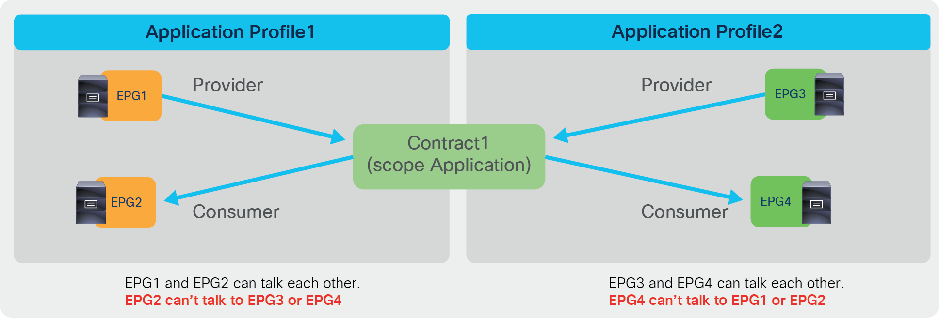
● Application: A contract will only program rules between EPGs that are defined within the same application profile. Use of the same contract across other application profile EPGs will not allow for crosstalk between them.
● VRF (default): A contract will program rules between EPGs that are defined within the same VRF. Use of the same contract across other application profile EPGs will allow for crosstalk between them as long as they are in the same VRF.
● Tenant: A contract will program rules between EPGs that are defined within the same tenant. If there are EPGs tied to multiple VRFs within a single tenant, and they consume/provide the same contract, this scope can be used to allow inter-VRF communication.
● Global: A contract will program rules between EPGs across any tenant within an ACI fabric. This is the highest possible scope of the definition, and great care should be taken when this is enabled on previously defined contracts so as to prevent unintentional traffic flows.
Contract scope example (Application)

Contract scope example (VRF)
Contract scope configuration is at Tenant > Contracts > Standard > Contract_name. The default configuration is scope VRF.

Contract scope configuration
Inter-VRF route-leaking configuration
A contract configured with the right scope between EPGs of different VRFs is not enough in order to allow traffic forwarding between VRFs. Additional configurations are necessary for route-leaking between the VRFs and to enable the correct class ID derivation for traffic filtering.
As of Cisco APIC Release 4.2, and with EPGs, the configurations for route-leaking and class ID derivation are intertwined.
Inter-VRF route-leaking requires the following configurations:
● The consumer BD subnet scope must be set with “Shared between VRFs.”
● You need to configure a subnet under the provider EPG with the “Shared between VRFs” scope set and “no default gateway SVI.”
● The L3Out EPG subnet scope must be set with “Shared Route Control Subnet” and “Shared Security Import Subnet.”
The first two bullets are required for inter-VRF EPG-to-EPG contracts. The third configuration (third bullet) applies if the L3Out EPG is a consumer or a provider of the inter-VRF contract.
The BD subnet scope “Shared between VRFs” is disabled by default, which means the BD subnet is not leaked to other VRFs. To leak the consumer BD subnet to the provider VRF, the consumer BD subnet scope must be “Shared between VRFs.” The configuration is located at Tenant > Networking > Bridge Domains > Consumer_BD_name > Subnets.

Consumer BD subnet scope (Shared between VRFs)
With inter-VRF forwarding all filtering for traffic between VRFs happens in the consumer VRF. Cisco ACI allows traffic from provider VRF to the consumer VRF, and filtering is performed within the consumer VRF. Traffic from the consumer VRF to the provider VRF is not allowed by default. Consumer VRF enforcement is explained in the next subsection.
The subnet that you enter under the provider EPG is used by ACI to program correctly the consumer VRF in order to match the destination IP to the subnet and derive the destination class ID. The configuration location is at Tenant > Application Profiles > Application_Profile_name > Application EPGs > Provider_EPG_name > Subnets.
Do realize that while the subnet under the provider EPG could also be used as a default gateway for the provider BD, it’s preferred to keep the default gateway on the BD itself and to configure the subnet under the provider EPG with a “No Default SVI Gateway” option. This option ensures that the subnet under the EPG is just used for route-leaking and classification purposes and not as a default gateway.

Provider EPG subnet (Shared between VRFs)
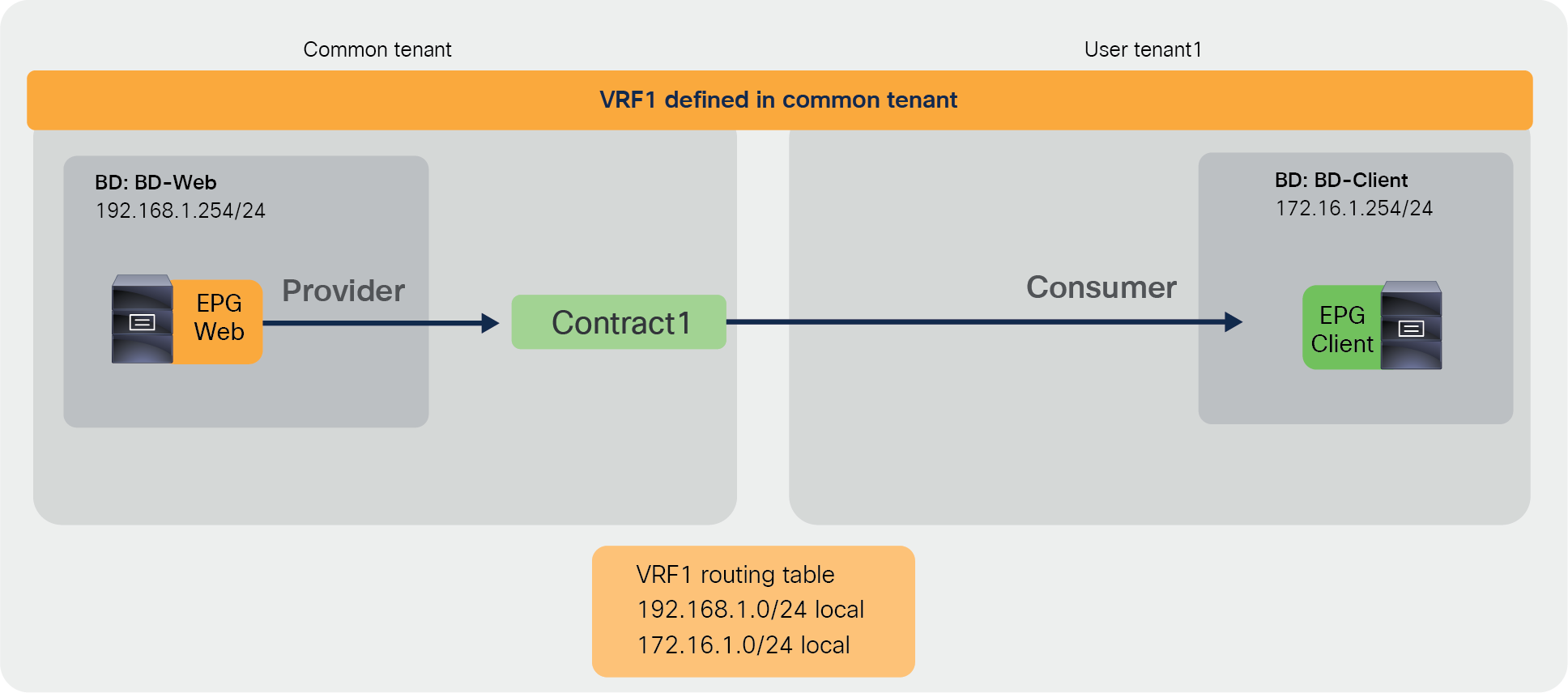
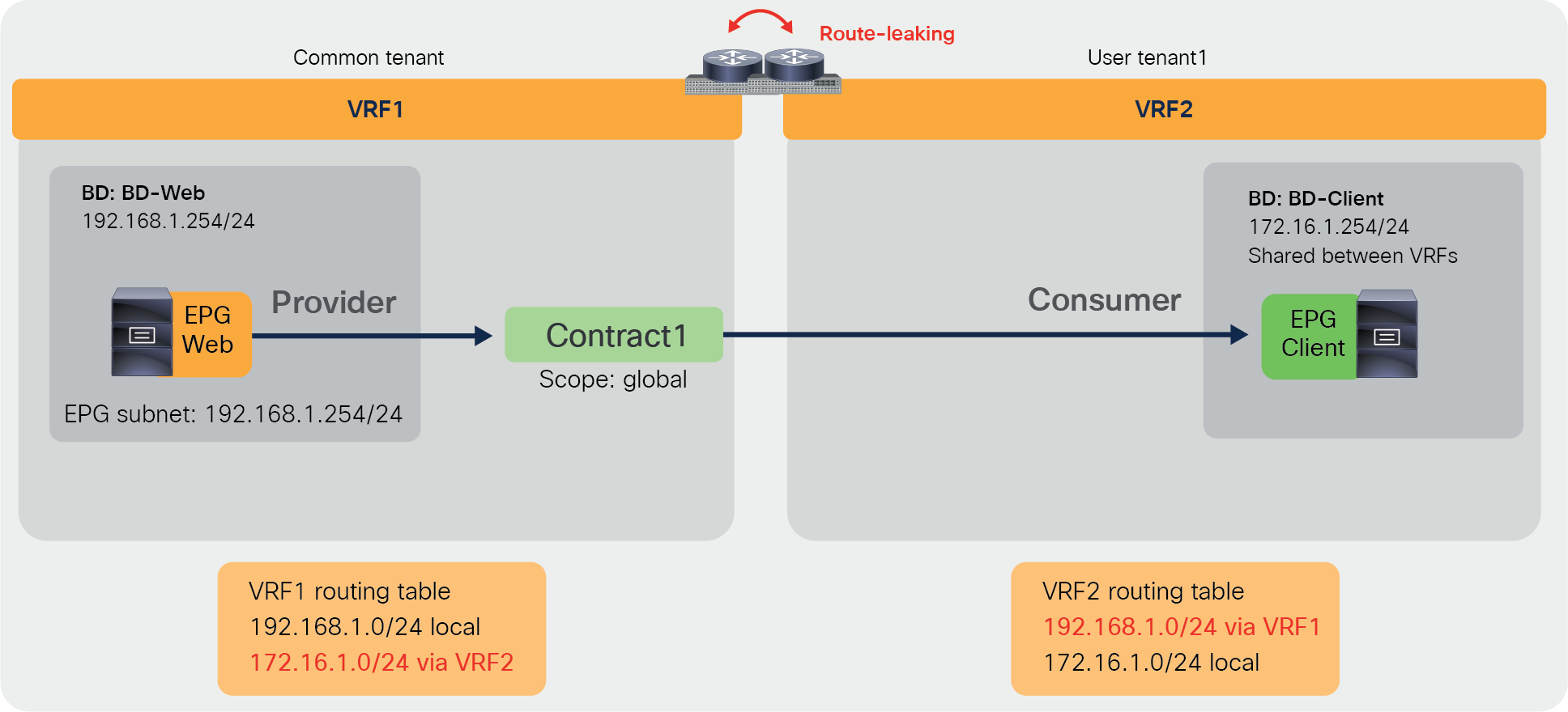
Once the contract scope, the consumer BD subnet, and the provider EPG subnet are configured correctly, each VRF leaks the subnet to the other VRF. The CLI output below shows provider VRF1 and consumer VRF2 routing tables.
Pod1-Leaf1# show ip route vrf tenant1:VRF1
<snip>
172.16.1.0/24, ubest/mbest: 1/0, attached, direct, pervasive
*via 10.0.16.66%overlay-1, [1/0], 00:00:14, static, tag 4294967294
192.168.1.0/24, ubest/mbest: 1/0, attached, direct, pervasive
*via 10.0.16.66%overlay-1, [1/0], 00:11:30, static, tag 4294967294
192.168.1.254/32, ubest/mbest: 1/0, attached, pervasive
*via 192.168.1.254, vlan93, [0/0], 00:11:30, local, local
Pod1-Leaf1# show ip route vrf tenant1:VRF2
<snip>
172.16.1.0/24, ubest/mbest: 1/0, attached, direct, pervasive
*via 10.0.16.66%overlay-1, [1/0], 00:11:34, static, tag 4294967294
172.16.1.254/32, ubest/mbest: 1/0, attached, pervasive
*via 172.16.1.254, vlan97, [0/0], 00:11:34, local, local
192.168.1.0/24, ubest/mbest: 1/0, attached, direct, pervasive
*via 10.0.16.66%overlay-1, [1/0], 00:11:34, static, tag 4294967294
If L3Out EPG is the consumer or provider of the inter-VRF contract, “Shared Route Control Subnet” and “Shared Security Import Subnet” must be set at the L3Out EPG subnet in addition to “External Subnet for External EPG.” The configuration is located at Tenant > Networking > L3Outs > L3Out_name > External EPGs > Exteranal_EPG_name > Subnets.
● Shared Route Control Subnet: This option is to leak the routes to another VRF. This is an exact match. In case you want to match multiple subnets with one configuration, you can use the Aggregate option “Aggregate Shared Routes.” When, for example, both “Shared Route Control Subnet” and “Aggregate Shared Routes” are enabled for 10.0.0.0/8, Cisco ACI creates an IP prefix-list with “10.0.0.0/8 le 32,” which matches 10.0.0.0/8, 10.1.0.0/16, and so on.
● Shared Security Import Subnet: This option is to program the leaked subnet based L3Out EPG classification information on another VRF. This needs to be used with an “External Subnets for the External EPG” scope. This is required regardless of whether the L3Out EPG is a consumer or provider (unlike what happens with regular EPGs, where the subnet is only configured under the provider EPG).
The configuration is located at Tenant > Networking > L3Outs > L3Out_name > External EPGs > External_EPG_name > Subnets.

L3Out EPG subnet scope (Shared Route Control Subnet and Shared Security Import Subnet)
If an EPG is a consumer (or provider) of a contract that is provided (or consumed) by an L3Out of a different VRF, whether the BD subnet is announced via the L3Out depends on the following configurations (in addition to leaking the subnet to the VRF):
● L3Out association to a bridge domain (This option can’t be used if the L3Out is defined in a user tenant that is different from where the bridge domain is defined).
● “Export Route Control Subnet” scope configuration in the L3Out EPG subnet.
● Route Map/Profile in Export Direction with an explicit prefix-list.
Please see the Cisco ACI fabric L3Out guide for details: https://www.cisco.com/c/en/us/solutions/collateral/data-center-virtualization/application-centric-infrastructure/guide-c07-743150.html#_L3Out_Shared_Service.
Consumer VRF enforcement
In the case of inter-VRF contracts for EPG-to-EPG or EPG-to-L3Out (with the L3Out EPG configured as the provider), the consumer VRF enforces contract policies. Whereas consumer EPG classification is done at the consumer VRF just like with intra-VRF contracts, the derivation of the provider EPG class ID from the consumer VRF is based on looking up the subnet, because the consumer VRF always need to enforce policy regardless of the endpoint’s learning status.
Since the provider EPG class ID needs to be at another VRF, the provider EPG class ID uses a number from the global class ID range in order to avoid class ID conflict in the consumer VRF. The class ID allocation range is as follows:
● System-reserved: 1—15.
● Global allocation range: 16—16384 for inter-VRF provider EPGs. (The ID is unique per ACI fabric.)
● Local allocation range: 16385—65535 for VRF scoped EPGs. (The ID is unique per VRF.)
Figure 29 shows where to check the EPG class ID and the VRF scope, and Figure 30 provides an example (in this example, the provider Web EPG class ID is 10939, which is from the global range).
EPG class ID and VRF scope ID

Inter-VRF example
The consumer VRF has zoning rules to permit consumer-to-provider (49153-to-10939) and provider-to-consumer (10939-to-49153) traffic. An implicit deny rule is also created in the consumer VRF to deny traffic from the provider EPG to any (10939-to-0). This is done so that the provider EPG can’t talk to any endpoints in the consumer VRF unless a contract is a configured.
Pod1-Leaf1# show zoning-rule scope 2490372
+---------+--------+--------+----------+----------------+---------+---------+-------------------+----------+------------------------+
| Rule ID | SrcEPG | DstEPG | FilterID | Dir | operSt | Scope | Name | Action | Priority |
+---------+--------+--------+----------+----------------+---------+---------+-------------------+----------+------------------------+
| 4221 | 0 | 0 | implicit | uni-dir | enabled | 2490372 | | deny,log | any_any_any(21) |
| 4218 | 0 | 0 | implarp | uni-dir | enabled | 2490372 | | permit | any_any_filter(17) |
| 4219 | 0 | 15 | implicit | uni-dir | enabled | 2490372 | | deny,log | any_vrf_any_deny(22) |
| 4251 | 0 | 32770 | implicit | uni-dir | enabled | 2490372 | | permit | any_dest_any(16) |
| 4253 | 49153 | 10939 | default | bi-dir | enabled | 2490372 | tenant1:Contract1 | permit | src_dst_any(9) |
| 4254 | 10939 | 49153 | default | uni-dir-ignore | enabled | 2490372 | tenant1:Contract1 | permit | src_dst_any(9) |
| 4255 | 10939 | 0 | implicit | uni-dir | enabled | 2490372 | | deny,log | shsrc_any_any_deny(12) |
+---------+--------+--------+----------+----------------+---------+---------+-------------------+----------+------------------------+
The provider VRF has an implicit zoning-rule to permit inter-VRF traffic from the provider (10939 to 14). This is done so that the provider-to-consumer traffic is permitted at the provider VRF without “policy applied bit” set and the policy is enforced at the consumer VRF. Class ID 14 is the system-reserved class ID for inter-VRF traffic.
Pod1-Leaf1# show zoning-rule scope 2850817
+---------+--------+--------+----------+---------+---------+---------+------+-----------------+----------------------+
| Rule ID | SrcEPG | DstEPG | FilterID | Dir | operSt | Scope | Name | Action | Priority |
+---------+--------+--------+----------+---------+---------+---------+------+-----------------+----------------------+
| 4220 | 0 | 16386 | implicit | uni-dir | enabled | 2850817 | | permit | any_dest_any(16) |
| 4250 | 0 | 0 | implicit | uni-dir | enabled | 2850817 | | deny,log | any_any_any(21) |
| 4208 | 0 | 0 | implarp | uni-dir | enabled | 2850817 | | permit | any_any_filter(17) |
| 4249 | 0 | 15 | implicit | uni-dir | enabled | 2850817 | | deny,log | any_vrf_any_deny(22) |
| 4252 | 10939 | 14 | implicit | uni-dir | enabled | 2850817 | | permit_override | src_dst_any(9) |
+---------+--------+--------+----------+---------+---------+---------+------+-----------------+----------------------+
Note: If there is a configuration change and an EPG doesn’t provide an inter-VRF contract anymore, the EPG class ID will be changed to a value taken from the local class ID range (16385—65535), which may cause traffic disruption for any traffic that includes the EPG because the zoning-rules are reprogrammed as part of the class ID change.
Ingress leaf enforcement
In case of inter-VRF contracts for L3Out-to-L3Out or L3Out-to-EPG (with the L3Out EPG as a consumer), the ingress leaf enforces contract policies. It means the policy is applied on the first leaf hit by the packet.
Figure 31 and the CLI output from the “show zoning-rule” command, below the figure, provide an example of a policy programmed on a leaf for an L3Out-to-L3Out contract. (To simplify the example, Figure 31 doesn’t show all of the information. Each VRF should have other routes, such as the L3Out logical interface subnet and router IDs of the leaf nodes. If a dynamic routing protocol is used to advertise routes through the L3Outs, another L3Out EPG with an “Export Route Control Subnet” option is also needed to be configured.)

Inter-VRF example (L3Out-to-L3Out)
Both consumer and provider VRFs have zoning rules to permit consumer-to-provider (5482-to-5481) and provider-to-consumer (5481-to-5482) traffic. As both consumer and provider VRFs have specific rules to enforce the policy defined by the user-configured contract, there is no implicit deny rule with Class ID 14.
Pod1-Leaf1# show zoning-rule scope 2916356
+---------+--------+--------+----------+----------------+---------+---------+-------------------+----------+----------------------+
| Rule ID | SrcEPG | DstEPG | FilterID | Dir | operSt | Scope | Name | Action | Priority |
+---------+--------+--------+----------+----------------+---------+---------+-------------------+----------+----------------------+
| 4282 | 0 | 0 | implicit | uni-dir | enabled | 2916356 | | deny,log | any_any_any(21) |
| 4284 | 0 | 0 | implarp | uni-dir | enabled | 2916356 | | permit | any_any_filter(17) |
| 4225 | 0 | 15 | implicit | uni-dir | enabled | 2916356 | | deny,log | any_vrf_any_deny(22) |
| 4250 | 5481 | 5482 | 71 | uni-dir-ignore | enabled | 2916356 | tenant1:Contract1 | permit | fully_qual(7) |
| 4206 | 5482 | 5481 | 69 | bi-dir | enabled | 2916356 | tenant1:Contract1 | permit | fully_qual(7) |
+---------+--------+--------+----------+----------------+---------+---------+-------------------+----------+----------------------+
Pod1-Leaf1# show zoning-rule scope 2850817
+---------+--------+--------+----------+----------------+---------+---------+-------------------+----------+----------------------+
| Rule ID | SrcEPG | DstEPG | FilterID | Dir | operSt | Scope | Name | Action | Priority |
+---------+--------+--------+----------+----------------+---------+---------+-------------------+----------+----------------------+
| 4209 | 0 | 0 | implicit | uni-dir | enabled | 2850817 | | deny,log | any_any_any(21) |
| 4229 | 0 | 0 | implarp | uni-dir | enabled | 2850817 | | permit | any_any_filter(17) |
| 4207 | 0 | 15 | implicit | uni-dir | enabled | 2850817 | | deny,log | any_vrf_any_deny(22) |
| 4212 | 5482 | 5481 | 69 | bi-dir | enabled | 2850817 | tenant1:Contract1 | permit | fully_qual(7) |
| 4265 | 5481 | 5482 | 71 | uni-dir-ignore | enabled | 2850817 | tenant1:Contract1 | permit | fully_qual(7) |
+---------+--------+--------+----------+----------------+---------+---------+-------------------+----------+----------------------+
In addition to the rules described above, Cisco ACI programs implicit deny rules depending on the L3Out EPG subnet configuration (please note that the information in this paragraph is for advanced readers). Figure 32 and the CLI output from the “show zoning-rule” command, below the figure, illustrate an example. VRF2 has the route 10.0.0.0/8 learned through the L3Out in VRF2 and leaks the subnet 10.0.0.0/8 to VRF1, but only IPs in the 10.0.0.0/16 subnet are supposed to communicate with L3Out-EPG1 (192.168.1.0/24) in VRF1. To achieve this, L3Out-EPG2 requires two subnets with different scopes: 10.0.0.0/8 with “Shared Route Control Subnet” to leak the subnet to VRF1, and 10.0.0.0/16 with “External Subnets for External EPG” and “Shared Security Import Subnet” for the L3Out-EPG2 classification in VRF1 and VRF2. In this case, an IP in 10.0.0.0/16 is classified L3Out-EPG2, but other IPs in 10.0.0.0/8 are classified to the special class ID 13 in VRF2. Traffic from any to class ID 13 is implicitly dropped in VRF1, even though VRF1 has the leaked route to 10.0.0.0/8 from VRF2.

Inter-VRF example (L3Out-to-L3Out) with implicit deny rule
Pod1-Leaf1# show zoning-rule scope 2916356
+---------+--------+--------+----------+----------------+---------+---------+-------------------+----------+------------------------+
| Rule ID | SrcEPG | DstEPG | FilterID | Dir | operSt | Scope | Name | Action | Priority |
+---------+--------+--------+----------+----------------+---------+---------+-------------------+----------+------------------------+
| 4282 | 0 | 0 | implicit | uni-dir | enabled | 2916356 | | deny,log | any_any_any(21) |
| 4284 | 0 | 0 | implarp | uni-dir | enabled | 2916356 | | permit | any_any_filter(17) |
| 4225 | 0 | 15 | implicit | uni-dir | enabled | 2916356 | | deny,log | any_vrf_any_deny(22) |
| 4269 | 5481 | 0 | implicit | uni-dir | enabled | 2916356 | | deny,log | shsrc_any_any_deny(12) |
| 4265 | 5481 | 5482 | 71 | uni-dir-ignore | enabled | 2916356 | tenant1:Contract1 | permit | fully_qual(7) |
| 4212 | 5482 | 5481 | 69 | bi-dir | enabled | 2916356 | tenant1:Contract1 | permit | fully_qual(7) |
+---------+--------+--------+----------+----------------+---------+---------+-------------------+----------+------------------------+
Pod1-Leaf1# show zoning-rule scope 2850817
+---------+--------+--------+----------+----------------+---------+---------+-------------------+-----------------+----------------------+
| Rule ID | SrcEPG | DstEPG | FilterID | Dir | operSt | Scope | Name | Action | Priority |
+---------+--------+--------+----------+----------------+---------+---------+-------------------+-----------------+----------------------+
| 4209 | 0 | 0 | implicit | uni-dir | enabled | 2850817 | | deny,log | any_any_any(21) |
| 4229 | 0 | 0 | implarp | uni-dir | enabled | 2850817 | | permit | any_any_filter(17) |
| 4207 | 0 | 15 | implicit | uni-dir | enabled | 2850817 | | deny,log | any_vrf_any_deny(22) |
| 4206 | 5481 | 14 | implicit | uni-dir | enabled | 2850817 | | permit_override | src_dst_any(9) |
| 4276 | 5481 | 5482 | 71 | uni-dir-ignore | enabled | 2850817 | tenant1:Contract1 | permit | fully_qual(7) |
| 4204 | 5482 | 5481 | 69 | bi-dir | enabled | 2850817 | tenant1:Contract1 | permit | fully_qual(7) |
| 4245 | 0 | 13 | implicit | uni-dir | enabled | 2850817 | | deny | black_list(5) |
+---------+--------+--------+----------+----------------+---------+---------+-------------------+-----------------+----------------------+
The red-highlighted implicit deny rules are programmed on the consumer VRF and the provider VRF in addition to the zoning rules to permit consumer-to-provider (5482-to-5481) and provider-to-consumer (5481-to-5482) traffic. The provider VRF has the implicit zoning-rule to deny traffic from any to the special class ID 13 (Rule ID 4245), and the consumer VRF has the implicit zoning-rule to deny traffic from provider to any (Rule ID 4269). These are to deny inter-VRF traffic except between 192.168.1.0/24 and 10.0.0.0/16.
For example, traffic with destination IP 10.1.1.1 entering the fabric via the L3Out in VRF1 is classified to destination class ID 13 and dropped because of the implicit deny rule (0 to 13), whereas traffic with destination IP 10.0.0.1 is classified to the destination class ID 5482. Traffic with source IP 10.1.1.1 entering the fabric via the L3Out in VRF2 is also dropped because it is not classified to the L3Out-EPG2 class ID (5482). Even if inter-VRF traffic from L3Out-EPG1 is permitted in VRF1 on the ingress leaf because of the implicit permit rule (5481 to 14), VRF2 on the egress leaf drops the traffic unless a specific permit rule is in place, because of the implicit deny rule (5481 to 0).
Note: The behavior of inter-VRF contract with vzAny as the consumer is slightly different. Please see Advanced Use cases section for detail.
An inter-tenant contract is a contract where the provider and the consumer EPGs are in different tenants, but not necessarily in different VRFs.
The primary design and configuration difference between intra-tenant contracts and inter-tenant contracts is the “visibility” of the contract from both tenants: the contract object must be visible in both tenants.
There are two ways for a contract to be visible to both tenants:
● The contract is defined in the common tenant and therefore is visible to all tenants.
● The contract is defined in a user tenant and “exported” to a different tenant through the configuration called “contract interface.”
The scope of the contract depends on whether the contract is between VRFs or not.
This section categorizes the inter-tenant deployments based on where the contract definition is located and whether or not there is VRF leaking:
● Inter-tenant intra-VRF contract with contract in the common tenant.
● Inter-tenant inter-VRF contract with contract in the common tenant.
● Inter-tenant inter-VRF contract with contract in the user tenant.
Figure 33 illustrates the first design example. In this example, the administrator defines a VRF in the common tenant that is referred by BDs (to which the EPGs are attached) in different tenants. In this example, the two tenants are the common tenant and a user tenant (but you could also define a contract in a common tenant that is used by two user tenants). A variation of this design consists in defining a contract between EPGs of different user tenants that are using the same VRF from the common tenant, and a contract from the common tenant.
This type of design is very simple to implement, for the following reasons:
● There are no configurations required for route-leaking.
● Because you define the contract in the common tenant, this contract is automatically visible in any tenant (like any object configured in the common tenant); therefore, the EPG in the common tenant and in the user tenant can, respectively, provide (or consume) and consume (or provide) the contract.
Inter-tenant contract example (intra-VRF contract in the common tenant)
Note: Although this example uses an EPG in the common tenant as provider and an EPG in user tenant1 as consumer, it is also possible to configure the EPG in the common tenant as consumer and the EPG in user tenant1 as provider.
Figure 34 illustrates the second design example: an inter-tenant, inter-VRF contract with the contract defined in the common tenant. The example illustrates connectivity between the common tenant and a user tenant, each having its own VRF. In this case, the contract is an inter-VRF contract with route-leaking. The EPG in the common tenant and in the user tenant can, respectively, provide (or consume) and consume (or provide) the contract.
The configuration for this design includes the VRF leaking configuration that was described in the previous section and the definition of the contract in the common tenant, like the previous example. A variation of this design consists in using the contract in the common tenant between two user tenants, each having its own VRF.
Inter-tenant contract example (inter-VRF contract in the common tenant)
Note: Although this example uses an EPG in the common tenant as provider and an EPG in user tenant1 as consumer, it is also possible to configure the EPG in the common tenant as consumer and the EPG in user tenant1 as provider.
You could also define a contract in a user tenant and establish connectivity between user tenants, each with its own VRF, as in Figure 35. This example differs from the example in the previous figure because the contract object is defined in the user tenant itself (instead of the common tenant). Because of this, you need to define the contract in the provider tenant and use the export option to specify to which tenant to export it. The EPG in the consumer tenant must be configured to consume the contract interface.

Inter-tenant contract example (inter-VRF contract in user tenants)
Note: The provider tenant exports contract to the consumer tenant. It is not possible to export the contract from the consumer tenant and use it from the provider tenant.
Table 4 summarizes the configuration considerations. Contract export from the provider tenant to the consumer tenant is required unless a contract is defined in the common tenant because the contract defined in a user tenant cannot be referred from other tenants. For inter-VRF communication, the contract scope must be “global” and the route-leaking-related configurations explained in the previous section are required.
Table 4. Inter-tenant contract configuration considerations
| Design example |
Contract scope |
Contract export |
Route-leak
● Provider EPG subnet
● BD: “Shared between VRFs” option
● L3Out: “Shared Route Control Subnet” and “Shared Security Import Subnet”
|
| Intra-VRF contract in common tenant |
VRF or global |
Not required EPGs can consume and provide a contract in the common tenant. |
Not required |
| Inter-VRF contract in common tenant |
Global |
Not required EPGs can consume and provide a contract in the common tenant. |
Required |
| Inter-VRF contract in user tenant |
Global |
Required Provider EPG and contract must be in the same tenant. |
Required |
Because contract scope and route-leak configurations are covered in a previous section, this section explains how to export a contract to a consumer tenant.
Export contract
The configuration to export a contract is in provider Tenant > Contracts > Standard.
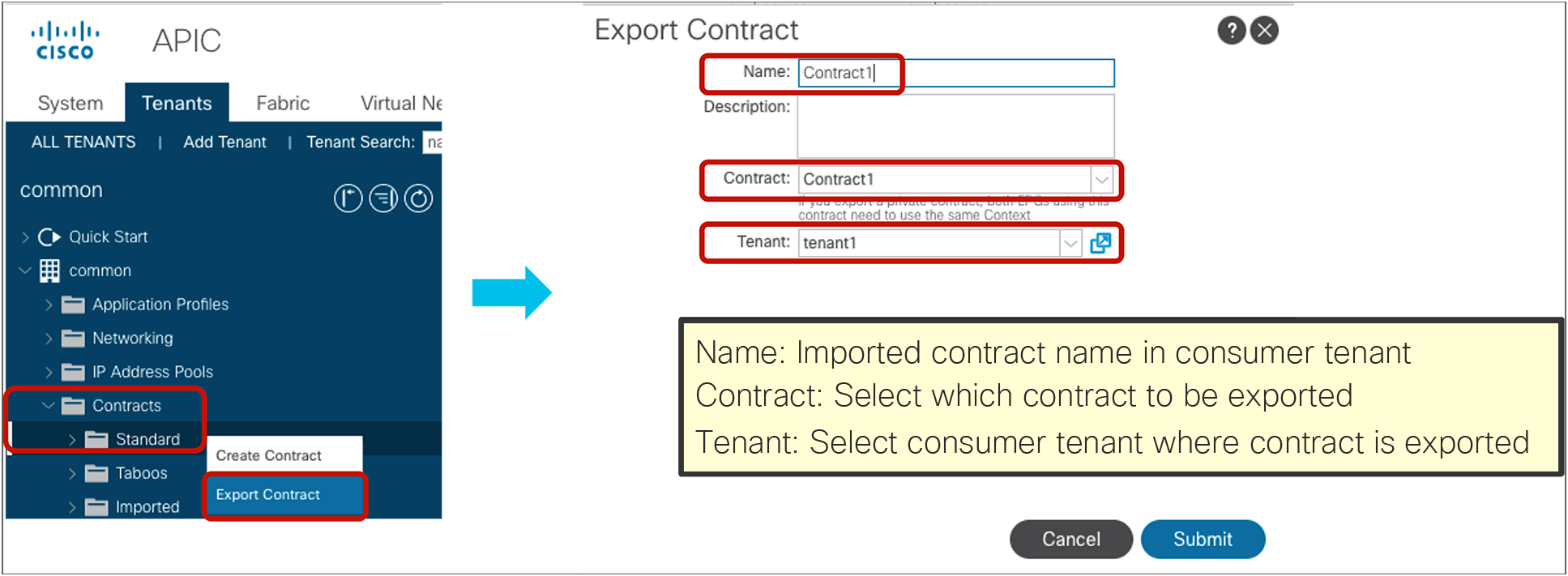
Export Contract
The tenant where the contract is exported can see the contract as “Imported Contract.” The configuration location is at consumer Tenant > Contracts > Imported.

Imported Contract
The consumer EPG can consume the imported contract by using “Add Consumed Contract Interface.”
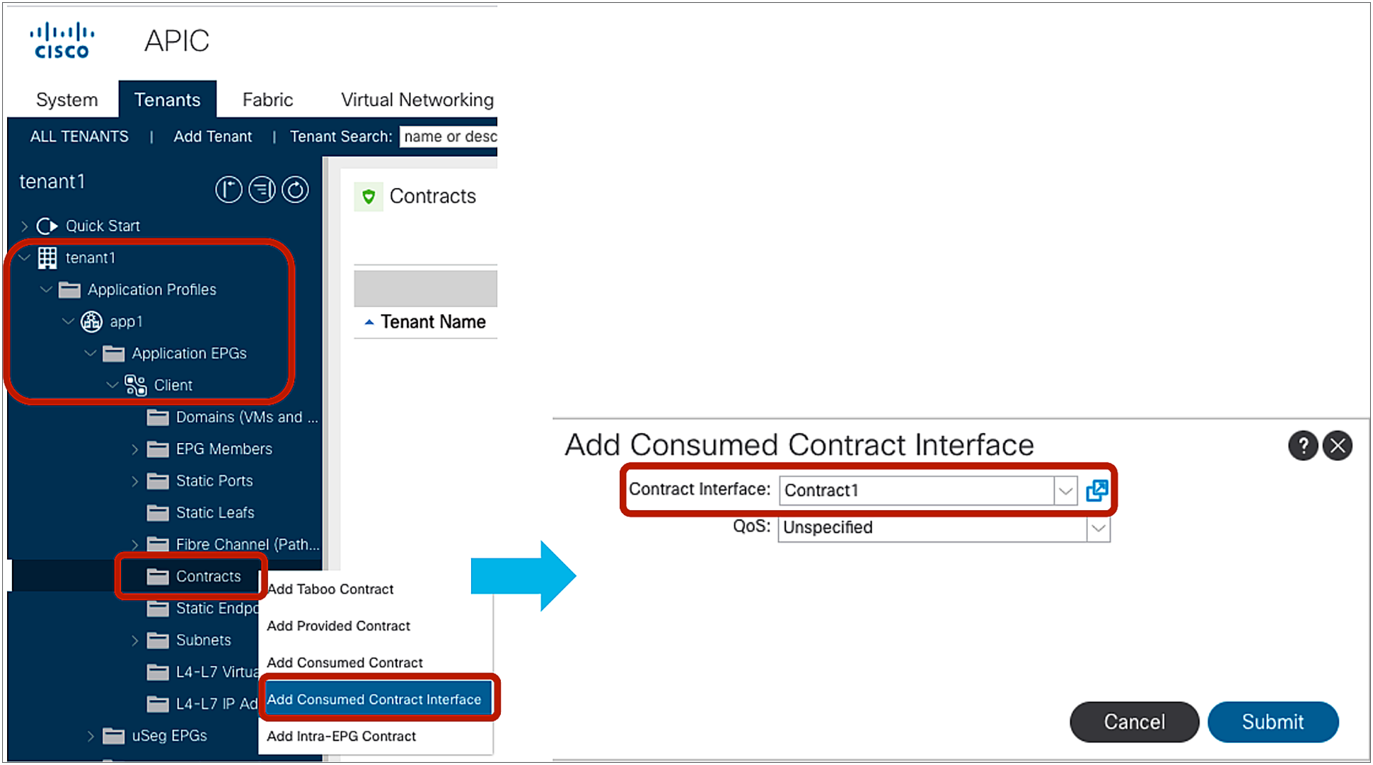
Consumed Contract Interface
Contract design options for migration and operational simplification
The fundamental security architecture of the Cisco ACI solution follows an allow-list model where we explicitly define what traffic should be permitted. Unless a VRF is configured in unenforced mode, all EPG-to-EPG traffic flows are implicitly dropped. As implied by the out-of-the-box allow-list model, the default VRF setting is in enforced mode. Traffic flows can be allowed or explicitly denied by implementing zoning rules on the leaf nodes.
Defining rules for all the allowed traffic can be complex, especially during the migration from an existing networking implementation. Because of this, Cisco ACI provides tools to make it easier to allow either all of the traffic in a given VRF, or to create one group of EPGs that are allowed to talk without any contracts, or to create security rules that apply to all EPGs in a VRF, or to define template EPGs with contracts.
The following list summarizes the options provided by Cisco ACI to simplify the adoption of contracts:
● Unenforced mode: All EPGs members in the VRF can communicate freely. This is a per-VRF configuration.
● Preferred groups: a group of EPGs per VRF where EPGs can communicate freely. Other EPGs still require contracts to communicate. Each VRF can have one preferred group.
● vzAny: vzAny represents all EPGs in the VRF. This option is also referred to as an “EPG Collection.” By applying contracts to vzAny, the administrator can create security rules that apply to all the EPGs in the VRF.
● EPG contract inheritance: This feature allows the administrator to configure an EPG to inherit the contracts of other EPGs, which are used as a “master.” This feature allows organizing contracts in a more manageable way for complex configuration.
● Labels: This feature allows the administrator to select which EPGs can consume or provide contracts from other EPGs. By using labels to “group” those EPGs that can communicate, contracts configuration can be potentially simplified.
Each VRF has a policy enforcement option to define whether security policy is enforced on the VRF. By default, the VRF is in enforced mode, which means that a contract is required to let inter-EPG communication work. If a VRF instead is in unenforced mode, all EPGs in the VRF can communicate freely. This is useful for the situation where no security policy enforcement is required at all in a VRF.

VRF unenforced mode
The configuration location is at Tenant > Networking > VRFs > VRF_name > Policy.

VRF Policy Control Enforcement Preference
When a VRF is unenforced mode, regardless of any existing contract configuration, Cisco ACI programs an any-to-any permit rule only. As you would guess, unenforced mode can reduce the policy TCAM consumption on leaf nodes because, with this configuration, there’s only a permit any-to-any rule.
Pod1-Leaf1# show zoning-rule scope 2850817
+---------+--------+--------+----------+---------+---------+---------+------+--------+-----------------+
| Rule ID | SrcEPG | DstEPG | FilterID | Dir | operSt | Scope | Name | Action | Priority |
+---------+--------+--------+----------+---------+---------+---------+------+--------+-----------------+
| 4250 | 0 | 0 | implicit | uni-dir | enabled | 2850817 | | permit | any_any_any(21) |
+---------+--------+--------+----------+---------+---------+---------+------+--------+-----------------+
The main drawback of using unenforced mode is that no policy filtering or redirect can be enforced on the VRF at all. If most of the EPGs in the VRF should have open communication, but a few should have only limited communication with the other EPGs, you need to use the preferred group feature. With unenforced mode configured on a VRF, other features that require policy enforcement cannot be used on this VRF: for instance, you cannot apply Quality of Service (QoS) policies based on contracts, you cannot configure Cisco ACI to drop specific traffic between EPGs with the deny action, and you cannot configure ACI to redirect traffic (PBR: Policy Based Redirect).
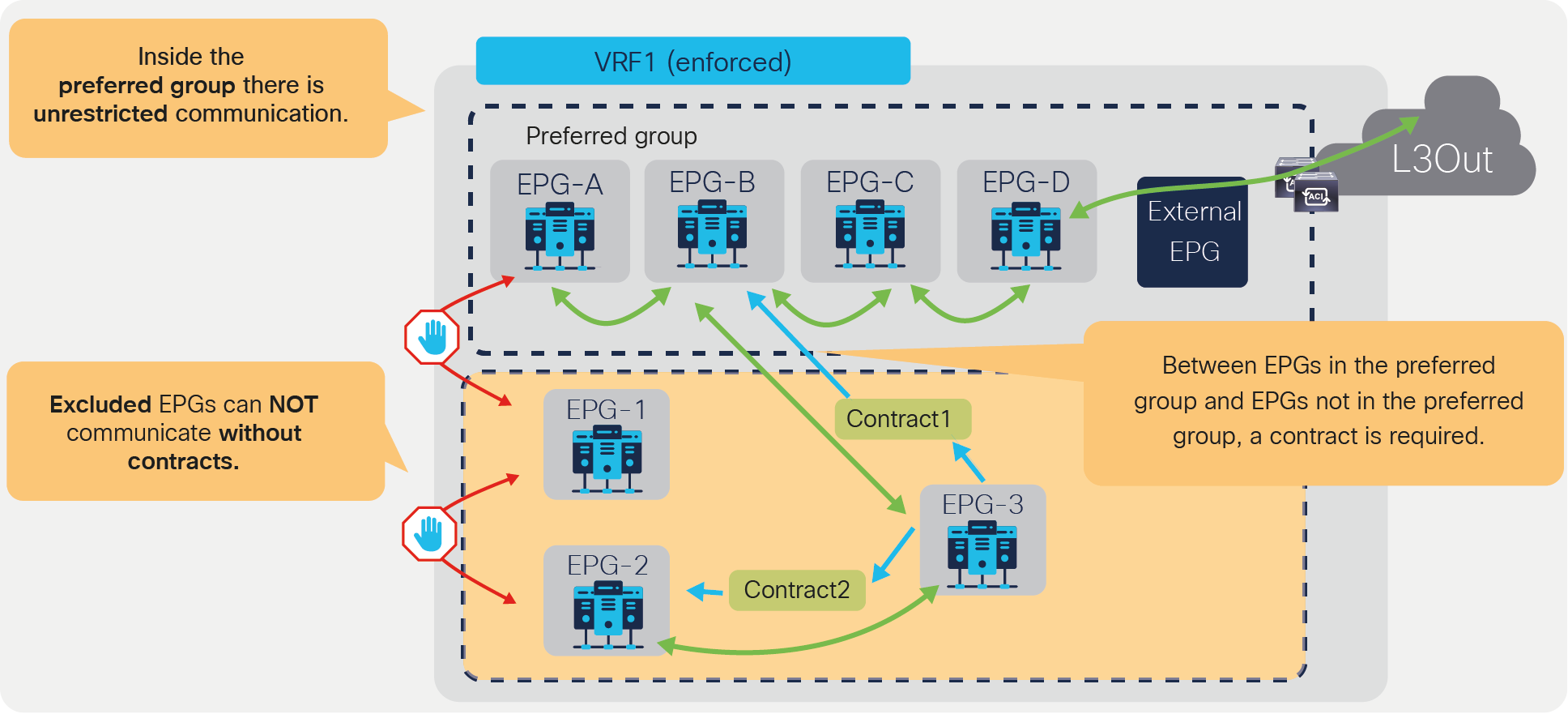
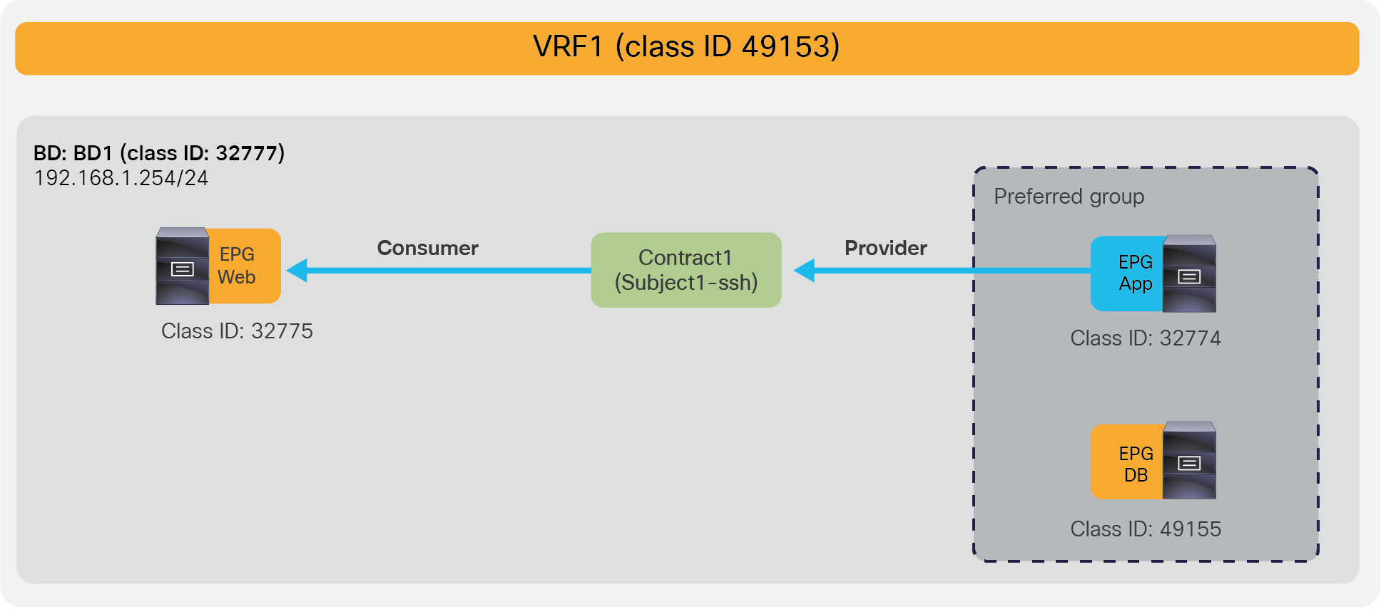
The preferred group feature was introduced in Cisco APIC Release 2.2. EPGs in the preferred group in the same VRF do not need a contract to communicate with each other. If either the consumer or provider EPG is not in the preferred group, a contract is still required to permit traffic between EPGs.
Preferred group
The preferred group configuration requires two steps:
1. Enable Preferred Group on the VRF.
2. Enable a preferred group configuration at EPG so that the EPG is in the preferred group.
The configuration for the first step is at Tenant > Networking > VRFs > VRF_name > Policy. The default configuration is “Disabled.” The VRF must be in enforced mode.
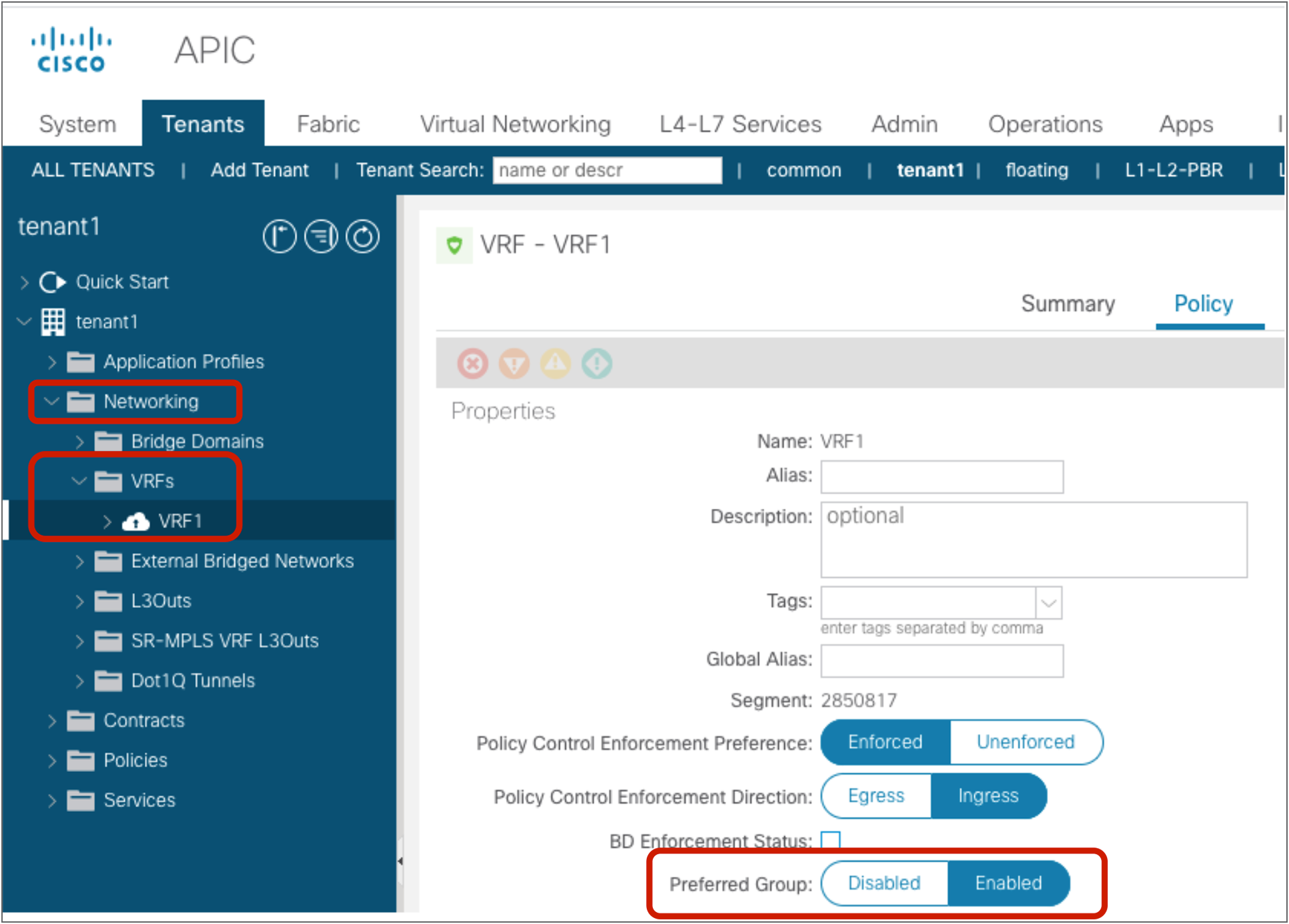
Preferred group configuration at VRF
The configuration for the second step is done at Tenant > Application Profiles > Application_Profile_name > Application EPGs > EPG_name > Policy > General. The default configuration is “Excluded.”

Preferred group configuration at EPG
Figure 44 and the CLI output from the “show zoning-rule” command, below the figure, illustrate an example of how Cisco ACI programs the leaf to implement the preferred group logic. The highlighted lines are the ones related to the preferred group configuration.
Preferred group example
Pod1-Leaf1# show zoning-rule scope 2850817
+---------+--------+--------+----------+----------------+---------+---------+-------------------+----------+----------------------------+
| Rule ID | SrcEPG | DstEPG | FilterID | Dir | operSt | Scope | Name | Action | Priority |
+---------+--------+--------+----------+----------------+---------+---------+-------------------+----------+----------------------------+
| 4250 | 0 | 0 | implicit | uni-dir | enabled | 2850817 | | permit | grp_any_any_any_permit(20) |
| 4208 | 0 | 15 | implicit | uni-dir | enabled | 2850817 | | deny,log | grp_any_dest_any_deny(19) |
| 4249 | 32775 | 32774 | 67 | bi-dir | enabled | 2850817 | tenant1:Contract1 | permit | fully_qual(7) |
| 4248 | 32774 | 32775 | 68 | uni-dir-ignore | enabled | 2850817 | tenant1:Contract1 | permit | fully_qual(7) |
| 4210 | 49153 | 0 | implicit | uni-dir | enabled | 2850817 | | deny,log | grp_src_any_any_deny(18) |
| 4231 | 32775 | 0 | implicit | uni-dir | enabled | 2850817 | | deny,log | grp_src_any_any_deny(18) |
| 4229 | 0 | 32775 | implicit | uni-dir | enabled | 2850817 | | deny,log | grp_any_dest_any_deny(19) |
| 4247 | 0 | 32777 | implicit | uni-dir | enabled | 2850817 | | permit | any_dest_any(16) |
+---------+--------+--------+----------+----------------+---------+---------+-------------------+----------+----------------------------+
In this example, App EPG and DB EPG are preferred group members while Web EPG is not. Web EPG can communicate with App EPG via SSH, but it cannot communicate with DB EPG. App EPG can communicate with DB EPG on any protocol or ports because these two EPGs are members of the preferred group.
As you can see from the “show zoning-rule” output, the communication between App EPG and EB EPG or any EPGs that are in the preferred group is achieved with an any-to-any implicit permit rule (Rule ID 4250). This rule allows all communication within the VRF.
If this was the only rule programmed by the preferred group in the VRF, all EPGs in the VRF would communicate freely, not just the ones that are in the preferred group. Instead, Cisco ACI creates deny rules, which have higher priority, to deny communication between non-preferred group members and any other EPGs. In this example, ACI programs rule to deny traffic from Web EPG to any other EPGs, and from any EPGs to the Web EPG (Rule IDs: 4231 and 4229).
If there was no other zoning rule, Web EPG wouldn’t be able to communicate with App EPG. Instead, Web EPG can talk to App EPG because the administrator configures a specific contract between the two EPGs, and this contract has a higher priority than the implicit deny rules programmed for the preferred group.
As a result, an endpoint in Web EPG can communicate with an endpoint in App EPG because of the contract (priority 7), but an endpoint in Web EPG cannot communicate with an endpoint in DB EBG because of the implicit deny rule created by the preferred group configuration (priority 18 and 19). An endpoint in App EPG can communicate with an endpoint in DB EPG because of the implicit permit rule created by the preferred group (priority 20).
In addition to the rules described so far, ACI programs two additional implicit rules (please note that the information in this paragraph is for advanced readers). Traffic entering the fabric via a L3Out configured with 0.0.0.0/0 subnet is classified with a special source class ID, the class ID of the VRF. Traffic from an EPG destined to the outside through an L3Out that is configured with the 0.0.0.0/0 subnet is classified with a destination class ID of 15. In the absence of a preferred group configuration, these traffic paths will hit an implicit deny rule unless a specific contract is in place. When using the preferred group feature instead, these traffic flows will hit an implicit permit rule programmed by the preferred group. In order to restore the default behavior for traffic between EPGs and the outside, ACI programs one implicit deny rule to drop traffic from the outside to the EPGs of the VRF and one to drop traffic from the EPGs to the outside:
● The implicit deny rule for traffic from VRF class ID to any (Rule ID: 4210) is created because of the preferred group configuration. This entry is to deny traffic from the L3Out EPG with 0.0.0.0/0 subnet to any in the VRF. (VRF class ID is used if the source is L3Out EPG with 0.0.0.0/0 subnet.) Otherwise, the traffic is permitted because of the any-to-any implicit permit rule (Rule ID: 4250).
● The implicit deny rule for traffic from any to 15 (Rule ID: 4208) is always created unless a VRF is in unenforced mode. If a preferred group is enabled, the priority is changed to 19 from 22. (Class ID 15 is used if the destination is L3Out EPG with 0.0.0.0/0 subnet.) Otherwise, the traffic is permitted because of the any-to-any implicit permit rule (Rule ID: 4250) that has priority 20.
The following list includes some key design considerations for using the preferred group feature:
● The preferred group feature does not necessarily help to reduce TCAM consumption. That depends on how many EPGs are not in the preferred group: the more EPGs are not in the preferred group, the more implicit deny rules are created.
● Due to CSCvm63145, an EPG in a preferred group can consume an inter-VRF contract, but cannot be a provider for an inter-VRF contract with an L3Out EPG as the consumer.
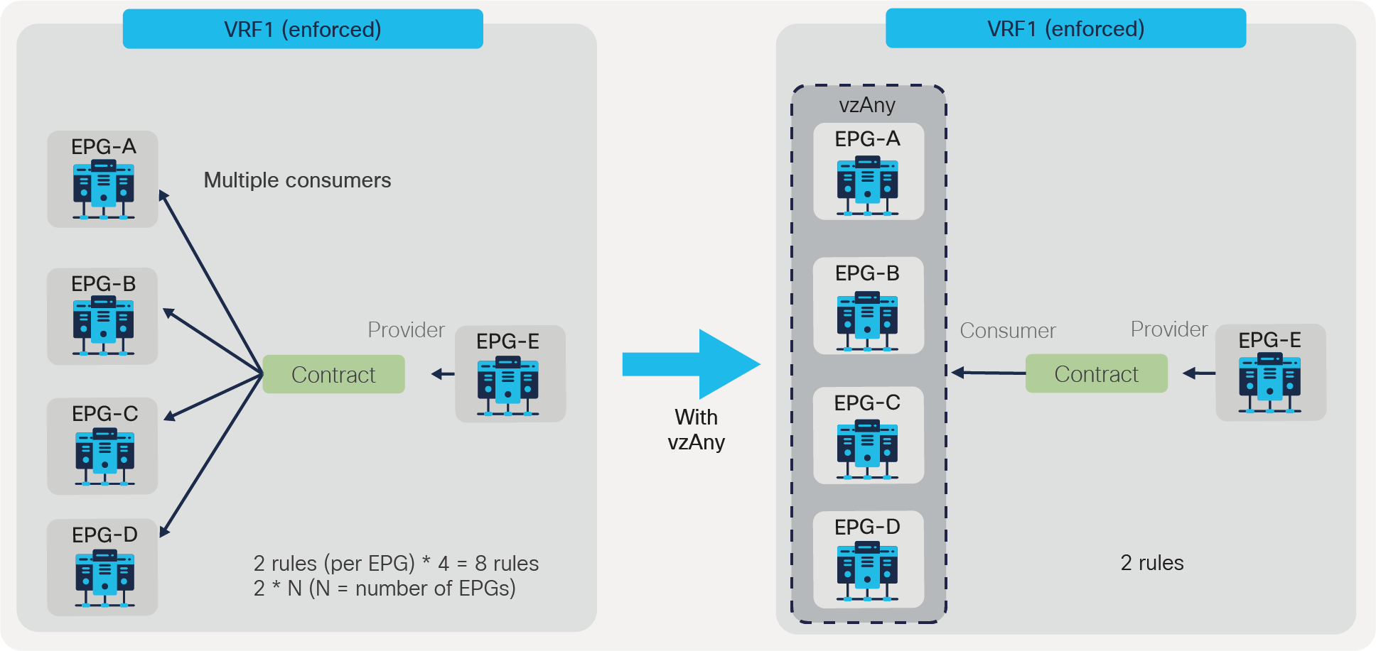
vzAny is an ”EPG Collection” that is defined under a given VRF. vzAny represents all EPGs, including the L3Out EPG in the VRF. The typical usage of vzAny is to allow flows between one EPG and all the other EPGs within the VRF through one contract connection instead of having multiple consumer or provider EPGs. The use of vzAny helps to simplify the configuration and to reduce policy TCAM consumption. Figure 45 provides an example. The left of the figure shows a configuration where EPG-A through EPG-D all consume the same contract from EPG-E. This configuration can be greatly simplified by using vzAny, which consumes the contract provided by EPG-E, reducing the number of policy-cam rules to two.
EPG to vzAny
Note: Care must be taken when using vzAny with inter-VRF contract. vzAny can be a consumer for inter-VRF contracts, but vzAny can’t be a provider for inter-VRF contract.
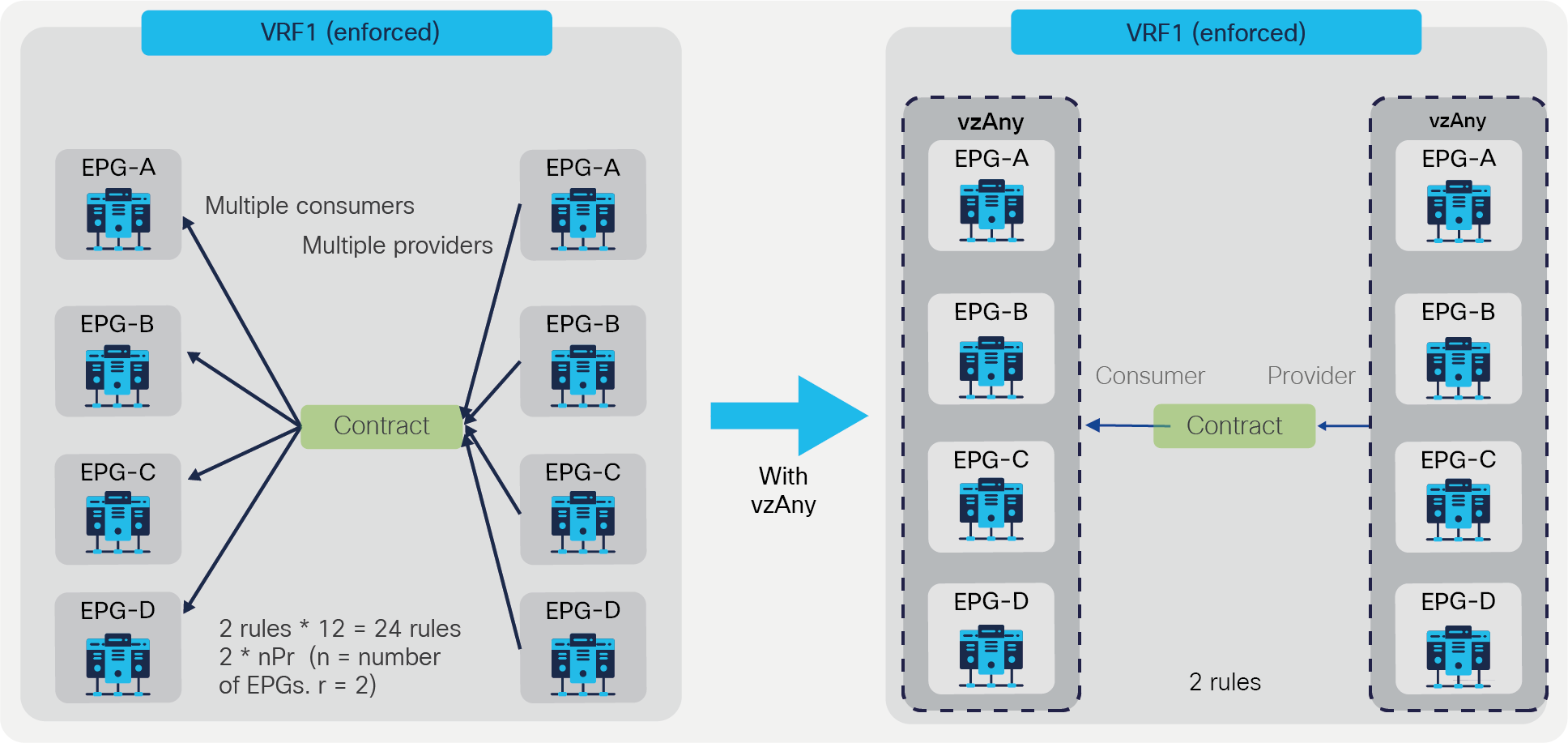
vzAny can be a consumer and also a provider to same contract for intra-VRF communication. This creates an any-to-any rule in the VRF. Figure 46 provides an example. In this example, EPG-A through EPG-D all must be able to talk with each other on a finite set of L4 ports, which is why a contract is used that is both provided and consumed by all the EPGs. This creates a number of rules in policy-cam. For this type of traffic filtering requirements, it’s much more practical to use vzAny, and also more efficient in terms of hardware programming, as you can see on the right of the figure below.
vzAny-to-vzAny example
The vzAny configuration is at Tenant > Networking > VRFs > VRF_name > EPG Collection for VRF.
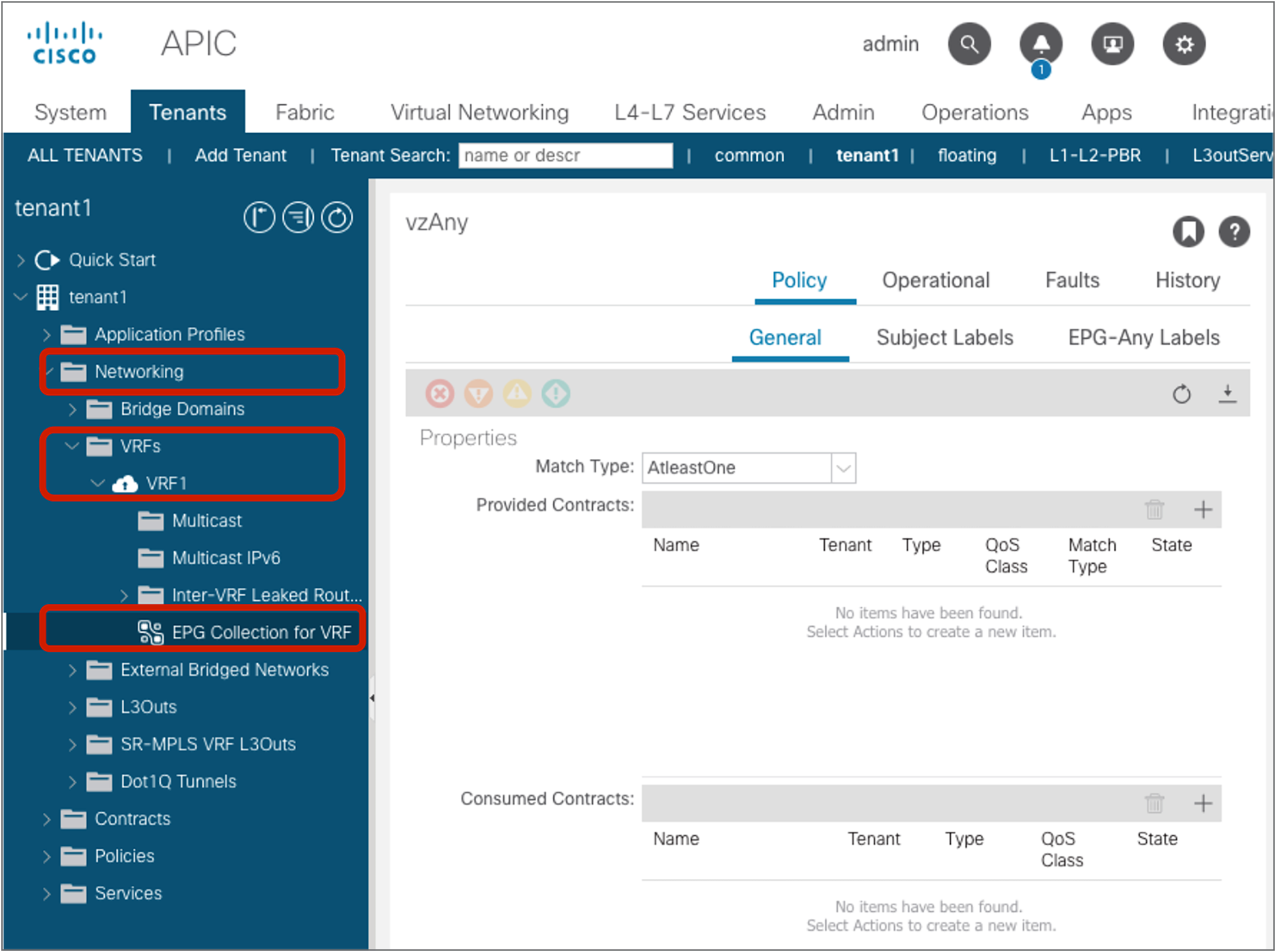
vzAny (EPG Collection for VRF)
Looking at the policy-cam programming helps understanding how configurations based on vzAny are translated into the hardware.
Figure 48 illustrates an example of a vzAny-to-EPG contract; the CLI output from “show zoning-rule” for this configuration appears below the figure.
In the example, EPG Client, Web, and App are consuming the same contract, which allows SSH traffic. This contract is provided by EPG DB. By matching the class ID numbers, you can see the equivalent entries from the policy-cam programming output. The value 0 used in the source or destination EPG (source or destination class ID) is the class ID that identifies vzAny; in other words, it is the equivalent of an “any” entry for the EPG values.
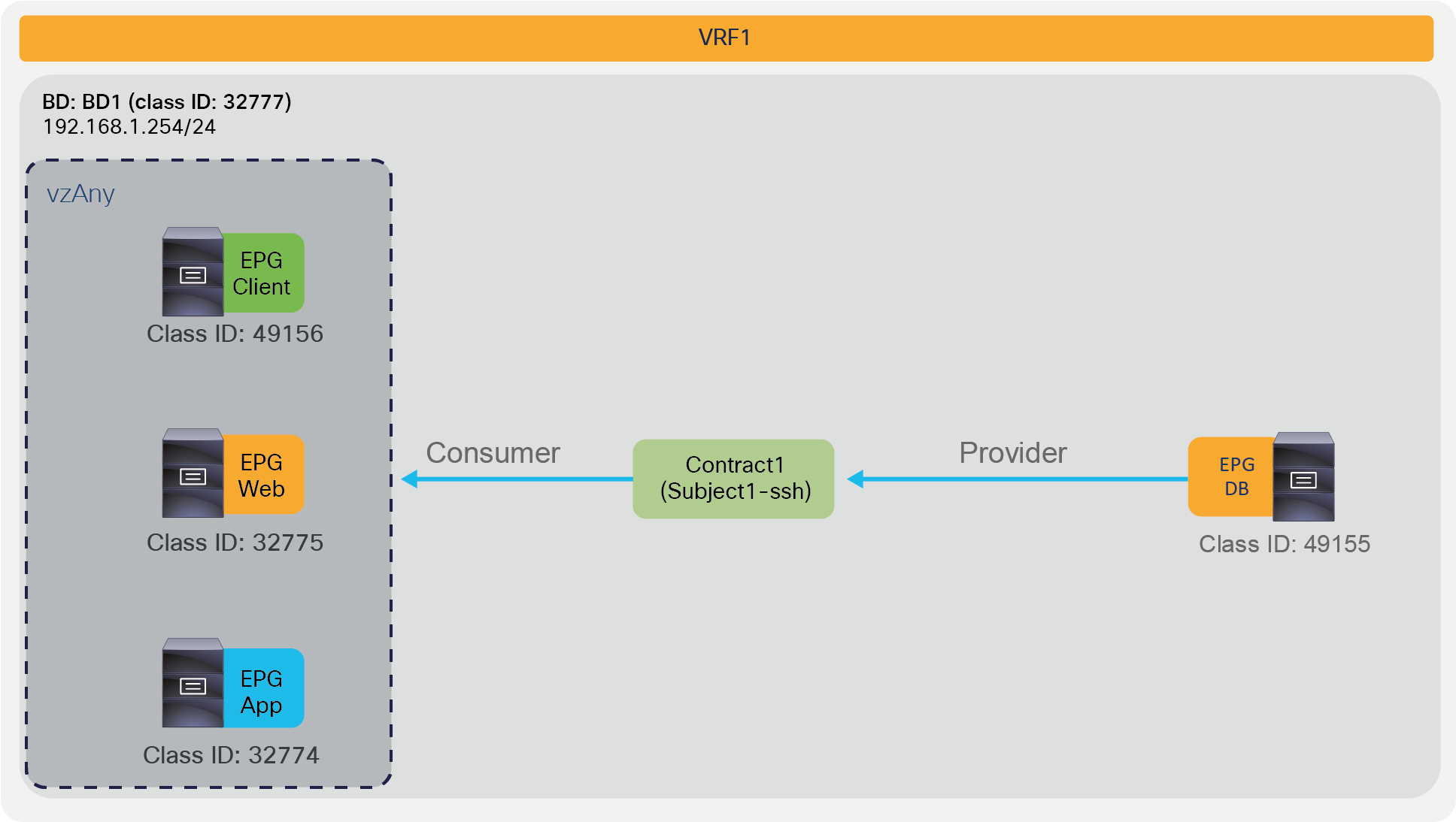
vzAny-to-EPG example
Pod1-Leaf1# show zoning-rule scope 2850817
+---------+--------+--------+----------+---------+---------+---------+-------------------+----------+----------------------+
| Rule ID | SrcEPG | DstEPG | FilterID | Dir | operSt | Scope | Name | Action | Priority |
+---------+--------+--------+----------+---------+---------+---------+-------------------+----------+----------------------+
| 4250 | 0 | 0 | implicit | uni-dir | enabled | 2850817 | | deny,log | any_any_any(21) |
| 4246 | 0 | 0 | implarp | uni-dir | enabled | 2850817 | | permit | any_any_filter(17) |
| 4208 | 0 | 15 | implicit | uni-dir | enabled | 2850817 | | deny,log | any_vrf_any_deny(22) |
| 4247 | 0 | 32777 | implicit | uni-dir | enabled | 2850817 | | permit | any_dest_any(16) |
| 4215 | 0 | 49155 | 67 | uni-dir | enabled | 2850817 | tenant1:Contract1 | permit | any_dest_filter(14) |
| 4222 | 49155 | 0 | 68 | uni-dir | enabled | 2850817 | tenant1:Contract1 | permit | src_any_filter(13) |
+---------+--------+--------+----------+---------+---------+---------+-------------------+----------+----------------------+
The red-highlighted lines are created because of Contract1 between DB EPG as provider and vzAny as consumer (Rule IDs 4215 and 4222). Even if you add other consumer EPGs for Contract1, no new zoning-rule gets programmed.
Figure 49 illustrates an example of a vzAny-to-vzAny contract; the CLI output from “show zoning-rule” for this configuration appears below the figure. In this example, EPG Client, Web, App, and DB are all allowed to talk with each other via SSH. Just as in the previous example, the value 0 used in the source and destination EPG (source and destination class ID) is the class ID that identifies vzAny; in other words, it is the equivalent of an “any” to “any” entry for the EPG values.
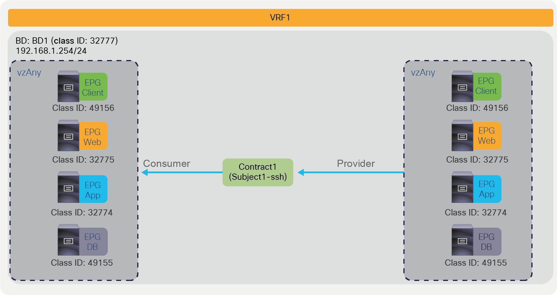
vzAny-to-vzAny example
Pod1-Leaf1# show zoning-rule scope 2850817
+---------+--------+--------+----------+----------------+---------+---------+-------------------+----------+----------------------+
| Rule ID | SrcEPG | DstEPG | FilterID | Dir | operSt | Scope | Name | Action | Priority |
+---------+--------+--------+----------+----------------+---------+---------+-------------------+----------+----------------------+
| 4250 | 0 | 0 | implicit | uni-dir | enabled | 2850817 | | deny,log | any_any_any(21) |
| 4246 | 0 | 0 | implarp | uni-dir | enabled | 2850817 | | permit | any_any_filter(17) |
| 4208 | 0 | 15 | implicit | uni-dir | enabled | 2850817 | | deny,log | any_vrf_any_deny(22) |
| 4247 | 0 | 32777 | implicit | uni-dir | enabled | 2850817 | | permit | any_dest_any(16) |
| 4229 | 0 | 0 | 68 | uni-dir-ignore | enabled | 2850817 | tenant1:Contract1 | permit | any_any_filter(17) |
| 4231 | 0 | 0 | 67 | bi-dir | enabled | 2850817 | tenant1:Contract1 | permit | any_any_filter(17) |
+---------+--------+--------+----------+----------------+---------+---------+-------------------+----------+----------------------+
The red-highlighted rules created by a vzAny-to-vzAny contract have a lower priority (priority 17) than an EPG-to-EPG contract (priority 7). The lower the priority number, the higher the priority; thus, if there is a specific EPG-to-EPG contract in addition to a contract with vzAny, the EPG-to-EPG contract wins. (If an unspecified filter is used in the contract, the priority for the rules created by vzAny-to-vzAny contract is 21 instead of 17, and the priority for the rules created by EPG-to-EPG contract is 9 instead of 7. The “Contract priorities” section explains the list of priorities.)
vzAny-to-vzAny rules apply to traffic between EPGs and not to traffic “within” the EPG (that is, to traffic from an EPG to itself). Please see “Contract priorities” section for details.
The use of vzAny helps to reduce policy TCAM consumption – with the exception of “Application Profile” contract scope. When a contract is provided and/or consumed by vzAny, it’s not recommended to use “Application Profile” contract scope. This is because the code to implement the desired behavior for a vzAny-to-vzAny contract with “Application Profile” scope is NOT implemented, and vzAny-to-EPG contract with “Application Profile” with more than one Application Profile per VRF, for each contract with Application Prpfile contract scope, APIC has to program the hardware with a configuration that is equivalent to having multiple contracts and a full mesh among the EPGs of each Application Profile. More specifically the implicitly created hardware programming is equivalent to having one contract per each Application Profile which is provided or consumed by the EPGs of that same Application Profile.
Figure 50 illustrates an example; the CLI output from “show zoning-rule” for this configuration; the CLI output from “show zoning-rule” for this configuration appears below the figure.
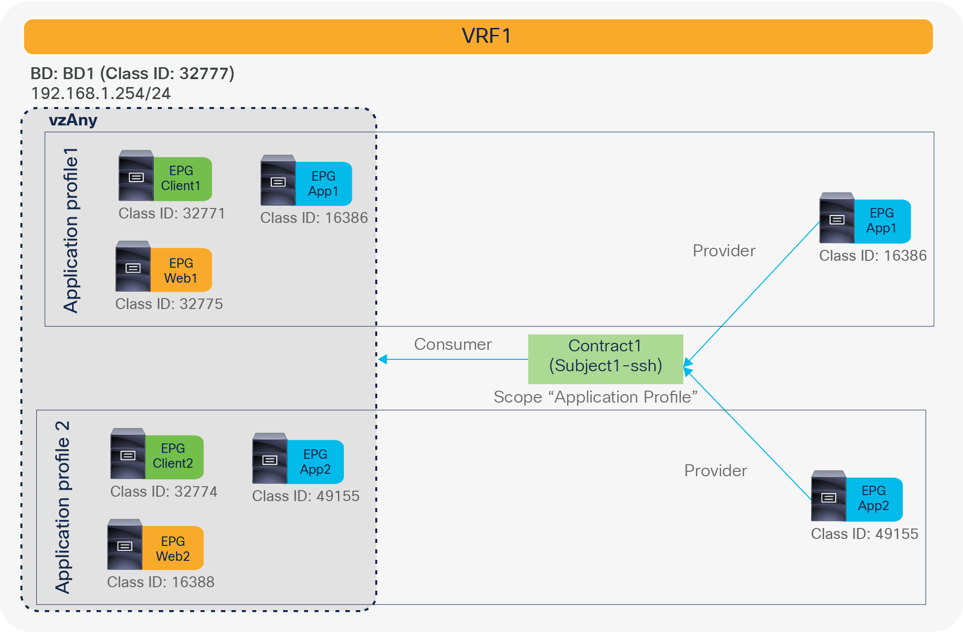
vzAny-to-EPG example with “Application Profile” contract scope (NOT recommended)
Pod1-Leaf1# show zoning-rule scope 2850817
+---------+--------+--------+----------+----------------+---------+---------+-------------------+----------+----------------------+
| Rule ID | SrcEPG | DstEPG | FilterID | Dir | operSt | Scope | Name | Action | Priority |
+---------+--------+--------+----------+----------------+---------+---------+-------------------+----------+----------------------+
| 4149 | 0 | 32777 | implicit | uni-dir | enabled | 2850817 | | permit | src_dst_any(9) |
| 4145 | 0 | 15 | implicit | uni-dir | enabled | 2850817 | | deny,log | any_vrf_any_deny(22) |
| 4144 | 0 | 0 | implarp | uni-dir | enabled | 2850817 | | permit | any_any_filter(17) |
| 4143 | 0 | 0 | implicit | uni-dir | enabled | 2850817 | | deny,log | any_any_any(21) |
| 4271 | 49155 | 16388 | 68 | bi-dir | enabled | 2850817 | tenant1:Contract1 | permit | fully_qual(7) |
| 4240 | 32774 | 49155 | 67 | uni-dir-ignore | enabled | 2850817 | tenant1:Contract1 | permit | fully_qual(7) |
| 4242 | 16388 | 49155 | 67 | uni-dir-ignore | enabled | 2850817 | tenant1:Contract1 | permit | fully_qual(7) |
| 4270 | 49155 | 32774 | 68 | bi-dir | enabled | 2850817 | tenant1:Contract1 | permit | fully_qual(7) |
| 4280 | 16386 | 32775 | 68 | uni-dir-ignore | enabled | 2850817 | tenant1:Contract1 | permit | fully_qual(7) |
| 4278 | 16386 | 32771 | 68 | uni-dir-ignore | enabled | 2850817 | tenant1:Contract1 | permit | fully_qual(7) |
| 4279 | 32771 | 16386 | 67 | bi-dir | enabled | 2850817 | tenant1:Contract1 | permit | fully_qual(7) |
| 4281 | 32775 | 16386 | 67 | bi-dir | enabled | 2850817 | tenant1:Contract1 | permit | fully_qual(7) |
+---------+--------+--------+----------+----------------+---------+---------+-------------------+----------+----------------------+
Contract inheritance was introduced in Cisco APIC Release 2.3. Contract inheritance is a feature to simplify configurations by letting an EPG inherit the contract-relation configuration from other EPGs. An EPG that is referred from other EPGs is called the master EPG. Figure 51 provides an example. If EPG1 is a master for EPG2, EPG2 automatically uses the same contracts as EPG1.

Contract inheritance overview1
If you then add a contract to EPG1, this is also added to EPG2 as EPG2 inherits contract-relation configurations of EPG1 (please see Figure 52).

Contract inheritance overview2
If you add a contract to EPG2, this is not added to EPG1 because EPG1 is the master of EPG2 (please see Figure 53).
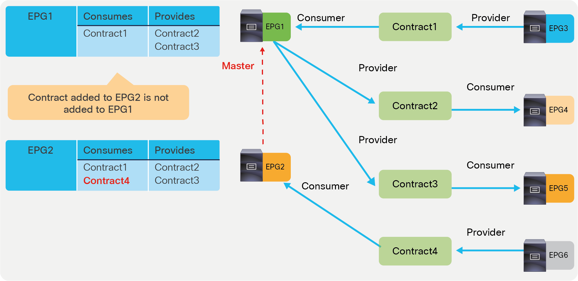
Contract inheritance overview3
If you need to apply the same security configuration to all the EPGs of a VRF, then vzAny is the better configuration choice, but if you need to apply the same set of contracts to a subset of the EPGs in the VRF, the use of Master EPG can be useful.
The configuration location is at Tenant > Application Profiles > Application_Profile_name > Application EPGs > EPG_name > Policy > General > EPG Contract Master.
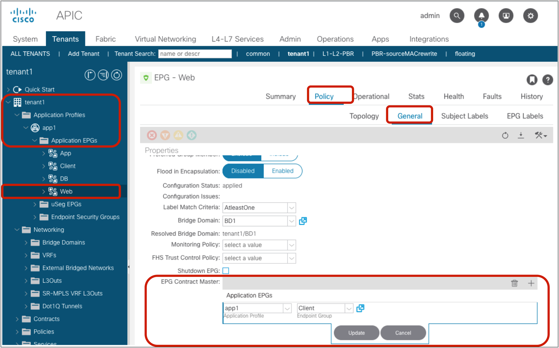
Contract inheritance configuration
Figure 55 and the CLI output from the “show zoning-rule” command, below the figure, illustrate an example of a policy programmed on a leaf for contract inheritance.

Contract inheritance example
Pod1-Leaf1# show zoning -rule scope 2850817
+---------+--------+--------+----------+----------------+---------+---------+-------------------+----------+----------------------+
| Rule ID | SrcEPG | DstEPG | FilterID | Dir | operSt | Scope | Name | Action | Priority |
+---------+--------+--------+----------+----------------+---------+---------+-------------------+----------+----------------------+
| 4250 | 0 | 0 | implicit | uni-dir | enabled | 2850817 | | deny,log | any_any_any(21) |
| 4246 | 0 | 0 | implarp | uni-dir | enabled | 2850817 | | permit | any_any_filter(17) |
| 4208 | 0 | 15 | implicit | uni-dir | enabled | 2850817 | | deny,log | any_vrf_any_deny(22) |
| 4247 | 0 | 32777 | implicit | uni-dir | enabled | 2850817 | | permit | any_dest_any(16) |
| 4222 | 49156 | 32774 | 67 | bi-dir | enabled | 2850817 | tenant1:Contract1 | permit | fully_qual(7) |
| 4244 | 32774 | 49156 | 68 | uni-dir-ignore | enabled | 2850817 | tenant1:Contract1 | permit | fully_qual(7) |
| 4248 | 32774 | 32775 | 68 | uni-dir-ignore | enabled | 2850817 | tenant1:Contract1 | permit | fully_qual(7) |
| 4214 | 32775 | 32774 | 67 | bi-dir | enabled | 2850817 | tenant1:Contract1 | permit | fully_qual(7) |
+---------+--------+--------+----------+----------------+---------+---------+-------------------+----------+----------------------+
The red-highlighted lines are created because of the master EPG configuration. Even though Web EPG doesn’t consume Contract1, permit rules between Web EPG and App EPG are created (Rule IDs 4248 and 4214), because they are inherited from the Client EPG that is the master EPG.
A single EPG can inherit from multiple master EPGs. Each master EPG can be kept without any endpoints and be used just as a template. It can be convenient to divide the security rules in multiple master EPGs.
● You can have, for instance, a master EPG for each operating system with the security rules that are specific to an OS (for example, Microsoft Windows, Linux, etc.). No endpoints would be associated with this EPG.
● You can have a master EPG for each geographical location, each with the specific security rules for each geographical location (for example, West, East). No endpoints would be associated with this EPG.
You would then be able to create (for example) the following type of EPGs with endpoints associated to them:
● An EPG for a Windows machine in the West, which inherits contracts from the master EPG Windows and the master EPG West.
● An EPG for a Windows machine in the East, which inherits contracts from the master EPG Windows and the master EPG East.
● An EPG for a Linux machine in the West, which inherits contracts from the master EPG Linux and the master EPG West.
With this approach, the work of maintaining the security rules for complex configurations can be simplified, because, to update a security rule specific to an OS or location, you would need to edit just one master EPG and not all the EPGs where endpoints are located.
Important points to consider about contract inheritance are the following ones:
● The master EPG is configured just like any other EPG; in fact, it is a regular EPG. Like all EPGs, it must be associated with a BD
● The master EPG and an EPG that refers to the master EPG must be under the same tenant.
● Contract inheritance is not applied to vzAny (vzAny can’t refer to a master EPG or be a master EPG.)
● Contract inheritance can simplify the configuration task, but it does not reduce TCAM resource consumption.
● Starting from APIC Release 4.2(6) and 5.0(1), contract inheritance with service graph is supported if the contract and EPGs are in the same tenant.
Labels are a configuration option that makes it possible to select which EPGs can consume or provide contracts from other EPGs. By using Labels to ”group” those EPGs that can communicate, contract configuration can be potentially simplified. Although the examples in this document use EPGs, labels can be used for EPGs, uSeg EPGs, ESGs and L3Out EPGs.
Figure 56 provides an example of EPG Label. Although the contract have multiple consumer and provider EPGs, zoning-rules are programmed only for the consumer and provider EPGs that have the same EPG Label. In this example, EPG1 and EPG2 that have same Label “Orange” can talk each other, and EPG3 and EPG4 that have same Label “Green” can talk to each other.
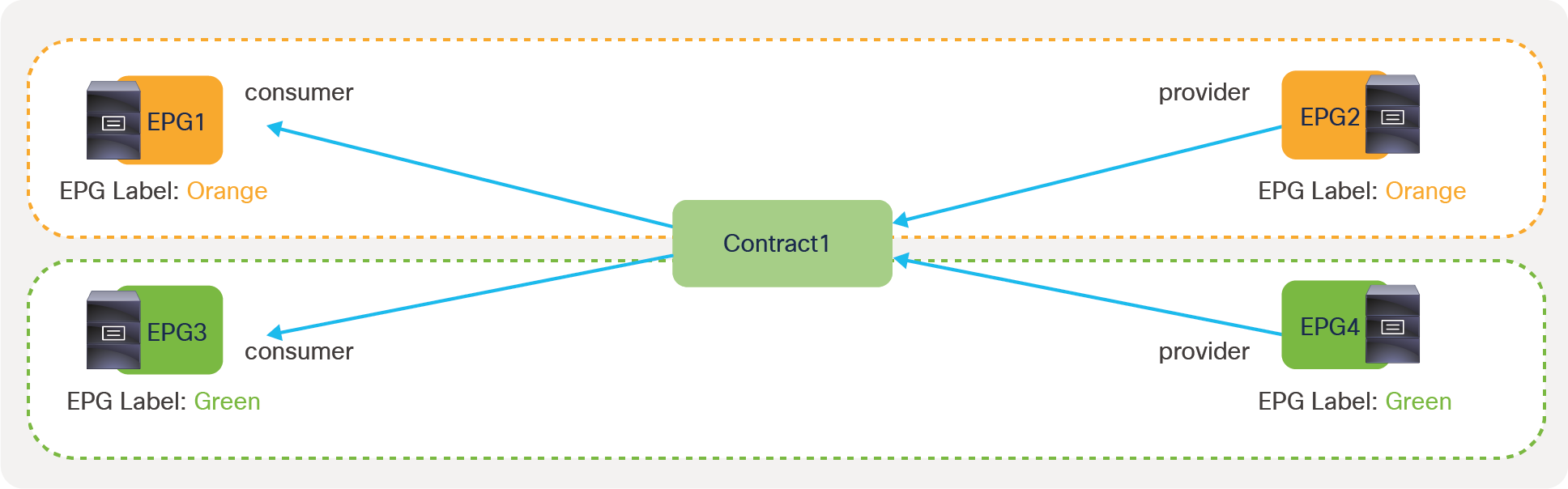
EPG label example
Figure 57 provides an example of Subject Label. Although the contract has multiple consumer and provider EPGs, zoning-rules are programmed only for the EPG that has the Label matched with the Label at the contract subject. In this example, Contract1 has two subjects: one is for SSH with Subject Label “Orange” and the other is for ICMP with Subject Label “Green”. SSH traffic is allowed between EPG1 and EPG2 only because there is no other consumer or provider EPG that has Subject Label “Orange”. ICMP traffic is allowed between EPG3 and EPG4 only because there is no other consumer or provider EPG that has Subject Label “Green”.

Subject label example
A Label configured at a contract subject is per direction: consumed or provided. Although the example in Figure 57 uses the same Label for the consumed and provided sides, different Label can be used for each direction. Figure 58 illustrates an example. If there is no Label at the provided side of Subject1-ssh, all provider EPGs part of Contract1 are applicable. Thus, SSH traffic is allowed between EPG1 and EPG2, and EPG1 and EPG4.

Subject Label example with No label
Label configurations are in multiple locations. If the grouping (for example, Orange, Green) is consistent across multiple contracts, the use of per EPG configuration instead of per contract configuration might be better as you don’t have to configure Label for each contract.
● Per EPG configurations:
◦ EPG Labels
◦ Subject Labels
● Per contract configurations:
◦ Contract Label (Label)
◦ Subject Label
In addition to that, Subject Label requires a Label configuration at a contract subject.
Per EPG configuration is at Tenant > Application Profiles > Application_Profile_name > Application EPGs > Consumer_EPG_name or Provider_EPG_name > Policy > Subject Labels or EPG Labels. Multiple Labels can be set for each direction (provided or consumed).

Per EPG configuration
Per contract configuration is at Tenant > Application Profiles > Application_Profile_name > Application EPGs > Consumer_EPG_name or Provider_EPG_name > Contracts > Contract_name. For each contract direction (consumer or provider), up to one Contract Label and one Subject Label can be set.

Per Contract configuration
In the case of Subject Labels, in addition to the Subject Label configuration at an EPG or a contract, Label configuration at the contract subject is required. The configuration is at Tenant > Contracts > Contract_name > Subject_name > Policy > Label. Multiple Labels can be set for each direction (provided or consumed).

Label configuration on a contract subject
The most important configuration is the text in “Name” such as “Orange” in previous figures. Tag (the colored square) is just for cosmetic purpose and is not used for Label matching.
In addition to Name and Tag, the provided side of EPG has the following options which are used to determine the zoning-rules to be programmed for which consumer and provider EPG combinations. The same logic is applied for Labels on a contract subject.
● Match:
◦ All: all consumer Labels must be matched with the provider Labels
◦ AtleastOne (default): at least one consumer Label must be matched with provider Labels.
◦ AtmostOne: at most one consumer Label must be matched with provider Labels.
◦ None: the consumer Label is empty or none of the consumer Labels is matched.
● Complement:
◦ False(default): If the Labels match, the contract will take effect
◦ True: If the Label does NOT match, the contract till take effect.
Please refer to Label Matching section in Cisco Application Centric Infrastructure Fundamentals for more details. Unless otherwise indicated, examples in this document use “AtleastOne” and Complement “False”.
Looking at the policy-cam programming helps understanding how configurations with Labels are translated into the hardware. Figure 62 illustrates an example of a contract with multiple consumer and provider EPGs; the CLI output from “show zoning-rule” for this configuration appears below the figure. By default, without Labels, zoning-rules are programmed for all the consumer and provider EPG combinations.

Example without Label (default)
Pod1-Leaf1# show zoning-rule scope 2195459
+---------+--------+--------+----------+----------------+---------+---------+-------------------+----------+----------------------+
| Rule ID | SrcEPG | DstEPG | FilterID | Dir | operSt | Scope | Name | Action | Priority |
+---------+--------+--------+----------+----------------+---------+---------+-------------------+----------+----------------------+
<snip>
| 4200 | 49157 | 32778 | 74 | uni-dir-ignore | enabled | 2195459 | tenant1:Contract1 | permit | fully_qual(7) |
| 4206 | 32778 | 49157 | 74 | bi-dir | enabled | 2195459 | tenant1:Contract1 | permit | fully_qual(7) |
| 4234 | 32778 | 32770 | 74 | bi-dir | enabled | 2195459 | tenant1:Contract1 | permit | fully_qual(7) |
| 4237 | 32770 | 32778 | 74 | uni-dir-ignore | enabled | 2195459 | tenant1:Contract1 | permit | fully_qual(7) |
| 4238 | 32770 | 16392 | 74 | uni-dir-ignore | enabled | 2195459 | tenant1:Contract1 | permit | fully_qual(7) |
| 4239 | 16392 | 32770 | 74 | bi-dir | enabled | 2195459 | tenant1:Contract1 | permit | fully_qual(7) |
| 4241 | 16392 | 49157 | 74 | bi-dir | enabled | 2195459 | tenant1:Contract1 | permit | fully_qual(7) |
| 4240 | 49157 | 16392 | 74 | uni-dir-ignore | enabled | 2195459 | tenant1:Contract1 | permit | fully_qual(7) |
+---------+--------+--------+----------+----------------+---------+---------+-------------------+----------+----------------------+
Figure 63 and the CLI output from the “show zoning-rule” command, below the figure, illustrate an example of a configuration and policies programmed on a leaf to implement the contract with EPG Labels. The highlighted lines are the ones related to the Label configuration.

Example with EPG Label at EPGs
Pod1-Leaf1# show zoning-rule scope 2195459
+---------+--------+--------+----------+----------------+---------+---------+-------------------+----------+----------------------+
| Rule ID | SrcEPG | DstEPG | FilterID | Dir | operSt | Scope | Name | Action | Priority |
+---------+--------+--------+----------+----------------+---------+---------+-------------------+----------+----------------------+
<snip>
| 4241 | 32770 | 16392 | 74 | uni-dir-ignore | enabled | 2195459 | tenant1:Contract1 | permit | fully_qual(7) |
| 4240 | 16392 | 32770 | 74 | bi-dir | enabled | 2195459 | tenant1:Contract1 | permit | fully_qual(7) |
| 4236 | 49157 | 32778 | 74 | uni-dir-ignore | enabled | 2195459 | tenant1:Contract1 | permit | fully_qual(7) |
| 4239 | 32778 | 49157 | 74 | bi-dir | enabled | 2195459 | tenant1:Contract1 | permit | fully_qual(7) |
+---------+--------+--------+----------+----------------+---------+---------+-------------------+----------+----------------------+
The orange-highlighted lines (Rule ID 4241 and 4240) are created for communication between EPG1 and EPG2 that have “Orange” Label. The green-highlighted lines (Rule ID 4236 and 4239) are created for communication between EPG3 and EPG4 that have “Green” Label.
Figure 64 and the CLI output from the “show zoning-rule” command, below the figure, illustrate an example of a configuration and policies programmed on a leaf to implement the contract with Subject Labels at EPGs. The highlighted lines are the ones related to the Label configuration.
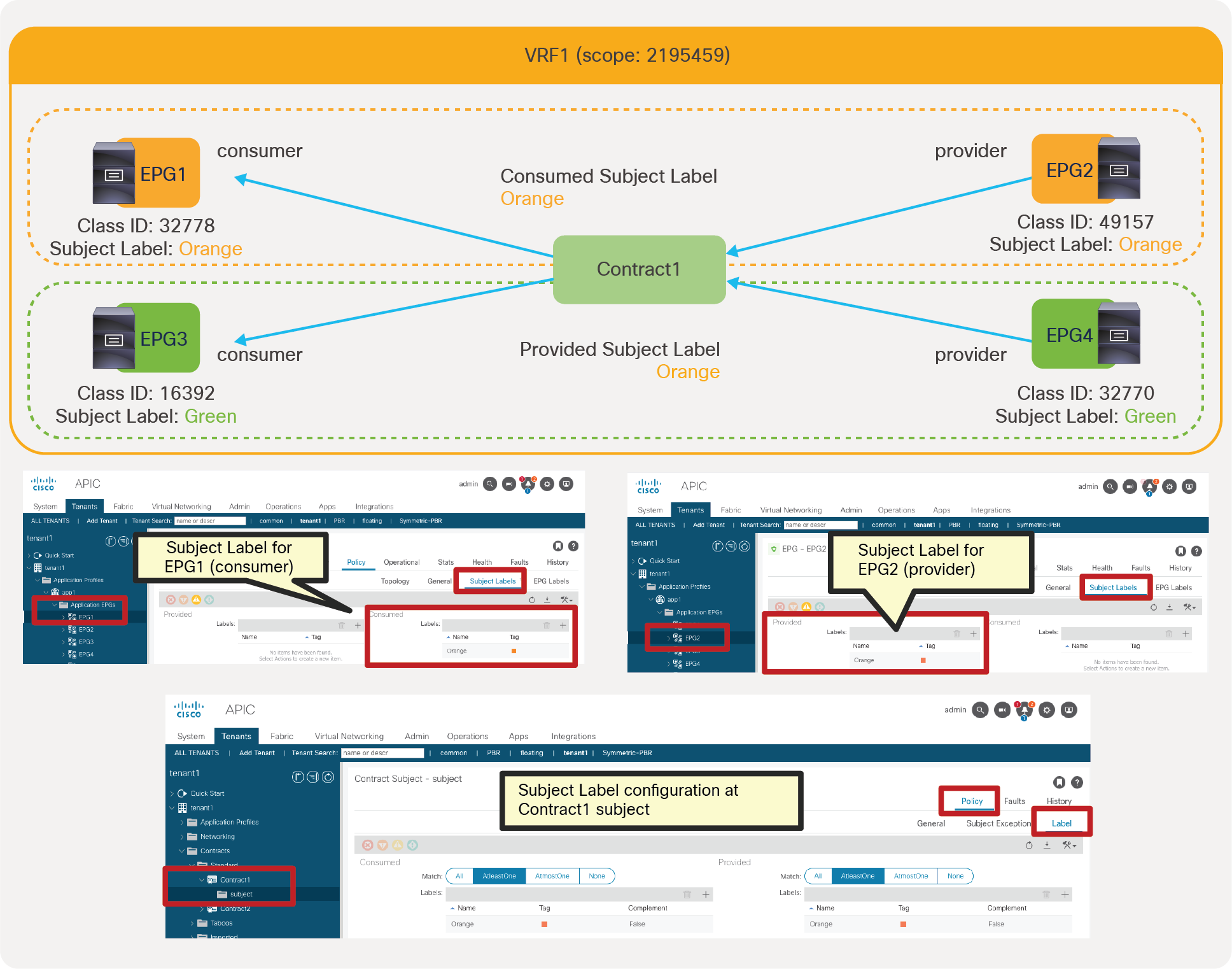
Example with Subject Label at EPGs
Pod1-Leaf1# show zoning-rule scope 2195459
+---------+--------+--------+----------+----------------+---------+---------+-------------------+----------+----------------------+
| Rule ID | SrcEPG | DstEPG | FilterID | Dir | operSt | Scope | Name | Action | Priority |
+---------+--------+--------+----------+----------------+---------+---------+-------------------+----------+----------------------+
<snip>
| 4241 | 32778 | 49157 | 10 | bi-dir | enabled | 2195459 | | permit | fully_qual(7) |
| 4240 | 49157 | 32778 | 10 | uni-dir-ignore | enabled | 2195459 | | permit | fully_qual(7) |
+---------+--------+--------+----------+----------------+---------+---------+-------------------+----------+----------------------+
The orange-highlighted lines are created because of Contract1 with Subject Labels. Even though two consumer and two provider EPGs are part of Contract1, only permit rules between EPG1 and EPG2 are created (Rule IDs 4241 and 4240), because that’s the only combination of consumer and provider EPGs matching the Contract1 subject Labels.
Figure 65 and the CLI output from the “show zoning-rule” command, below the figure, illustrate an example of a configuration and policies programmed on a leaf to implement the contract with Contract Labels at the contracts. The highlighted lines are the ones related to the Label configuration.
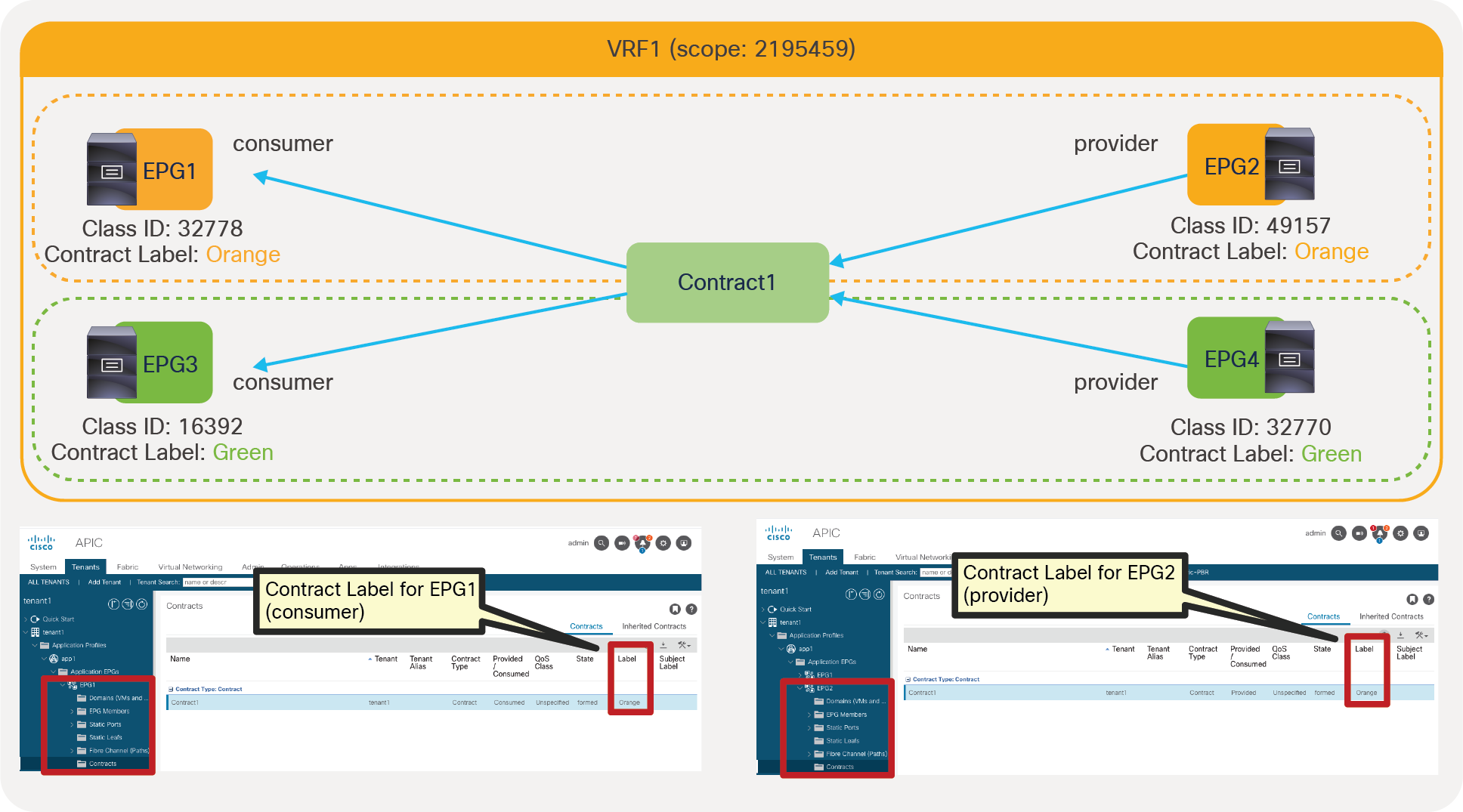
Example with Contract Labels at contracts under EPGs
Pod1-Leaf1# show zoning-rule scope 2195459
+---------+--------+--------+----------+----------------+---------+---------+-------------------+----------+----------------------+
| Rule ID | SrcEPG | DstEPG | FilterID | Dir | operSt | Scope | Name | Action | Priority |
+---------+--------+--------+----------+----------------+---------+---------+-------------------+----------+----------------------+
<snip>
| 4241 | 49157 | 32778 | 74 | uni-dir-ignore | enabled | 2195459 | tenant1:Contract1 | permit | fully_qual(7) |
| 4240 | 32778 | 49157 | 74 | bi-dir | enabled | 2195459 | tenant1:Contract1 | permit | fully_qual(7) |
| 4239 | 32770 | 16392 | 74 | uni-dir-ignore | enabled | 2195459 | tenant1:Contract1 | permit | fully_qual(7) |
| 4238 | 16392 | 32770 | 74 | bi-dir | enabled | 2195459 | tenant1:Contract1 | permit | fully_qual(7) |
+---------+--------+--------+----------+----------------+---------+---------+-------------------+----------+----------------------+
The orange-highlighted lines (Rule ID 4241 and 4240) are created for communication between EPG1 and EPG2 that have “Orange” Label. The green-highlighted lines (Rule ID 4239 and 4238) are created for communication between EPG3 and EPG4 that have “Green” Label.
Figure 66 and the CLI output from the “show zoning-rule” command, below the figure, illustrate an example of a configuration and policies programmed on a leaf to implement the contract with Subject Labels at the contract. The highlighted lines are the ones related to the Label configuration.
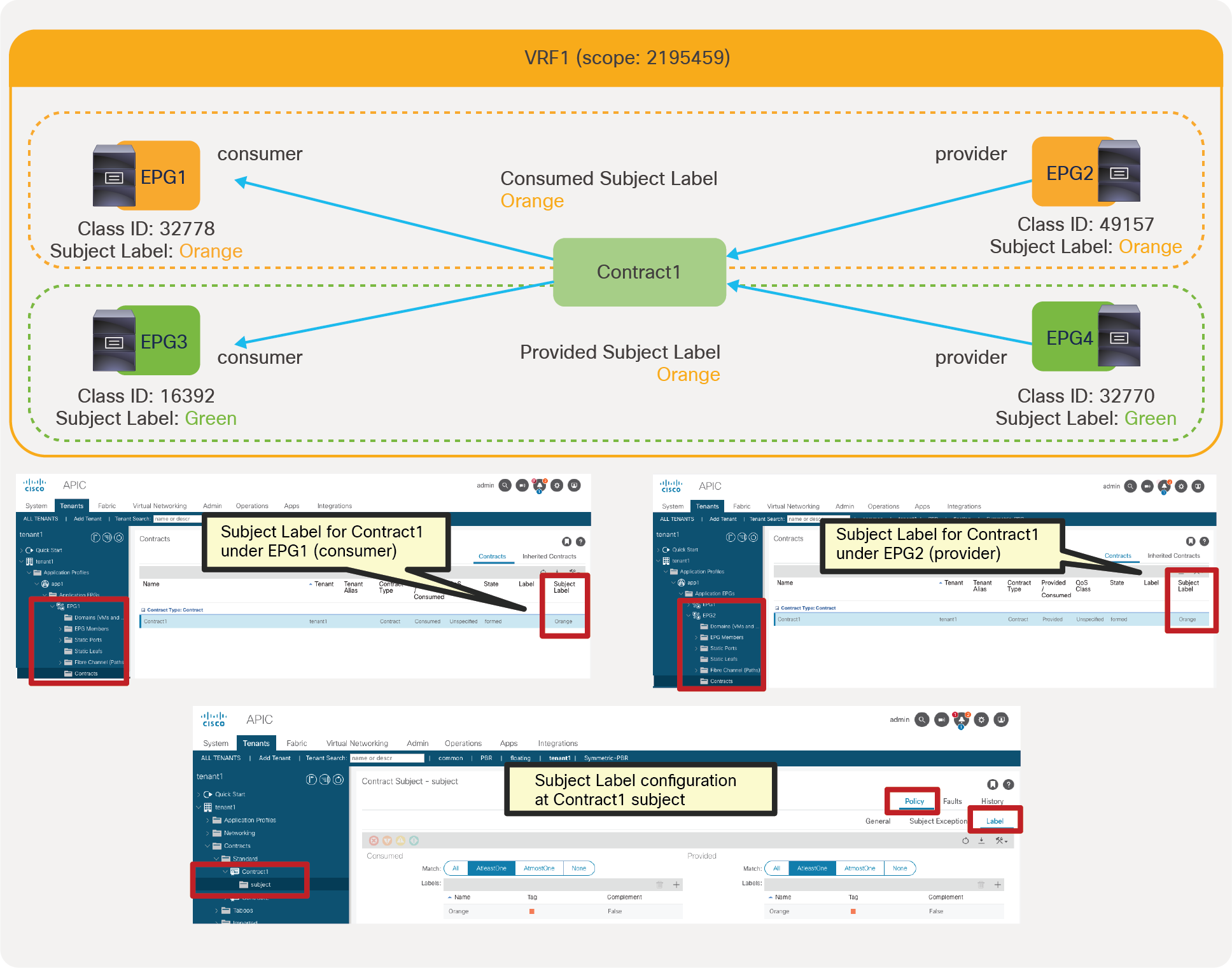
Example with Subject Labels at contracts under EPGs
Pod1-Leaf1# show zoning-rule scope 2195459
+---------+--------+--------+----------+----------------+---------+---------+-------------------+----------+----------------------+
| Rule ID | SrcEPG | DstEPG | FilterID | Dir | operSt | Scope | Name | Action | Priority |
+---------+--------+--------+----------+----------------+---------+---------+-------------------+----------+----------------------+
<snip>
| 4241 | 32778 | 49157 | 10 | bi-dir | enabled | 2195459 | | permit | fully_qual(7) |
| 4240 | 49157 | 32778 | 10 | uni-dir-ignore | enabled | 2195459 | | permit | fully_qual(7) |
+---------+--------+--------+----------+----------------+---------+---------+-------------------+----------+----------------------+
The orange-highlighted lines are created because of Contract1 with Subject Labels. Even though two consumer and two provider EPGs are part of Contract1, only permit rules between EPG1 and EPG2 are created (Rule IDs 4241 and 4240), because that’s the only combination of consumer and provider EPGs matching the Contract1 subject Labels.
For consumer EPGs of inter-tenant contracts, the contract needs to be exported to the consumer tenant unless the contract is in common tenant. In that case, Subject Labels at the imported contract in the consumer tenant are used to determine the matching instead of Subject Labels at the contract in the provider tenant. Other Labels: EPG Labels and Subject Labels at the consumer EPG and Contract Labels at the consumer EPG are not applicable. If the contract is in common tenant, this consideration is not applicable. All Label configurations can be used same as intra-VRF example.
The configuration location is at the consumer tenant > Contracts > Imported >Imported_contract_name (Figure 67).

Label configuration at the imported contract
Figure 68 and the CLI output from the “show zoning-rule” command for the consumer VRF, below the figure, illustrate an example of inter-tenant contract with Subject Label. (In the case of inter-VRF contract, the consumer VRF enforces policies.)
Inter-tenant contract with Subject Labels at the imported contract
Pod1-Leaf1# show zoning-rule scope 2195459
+---------+--------+--------+----------+----------------+---------+---------+------+----------+------------------------+
| Rule ID | SrcEPG | DstEPG | FilterID | Dir | operSt | Scope | Name | Action | Priority |
+---------+--------+--------+----------+----------------+---------+---------+------+----------+------------------------+
| 4206 | 5475 | 32778 | 10 | uni-dir-ignore | enabled | 2195459 | | permit | fully_qual(7) |
| 4241 | 32778 | 5475 | 10 | bi-dir | enabled | 2195459 | | permit | fully_qual(7) |
+---------+--------+--------+----------+----------------+---------+---------+------+----------+------------------------+
The orange-highlighted lines are created because of Contract1 with Subject Labels. Even though two consumer and two provider EPGs are part of Contract1, only permit rules between EPG1 and EPG2 are created (Rule IDs 4206 and 4241), because that’s the only combination of consumer and provider EPGs matching the Contract1 subject Labels.
Labels can be used with Contract Inheritance. Figure 69 and the CLI output from the “show zoning-rule” command, below the figure, illustrate an example of Contract inheritance with EPG Labels. When EPG3 inherits a contract from EPG1(master), APIC uses the Label configured under EPG1 for the contract inherited from EPG1, which is Contract1. APIC uses the label configured under EPG3 for the contract where EPG3 is directly involved, which is Contract2.
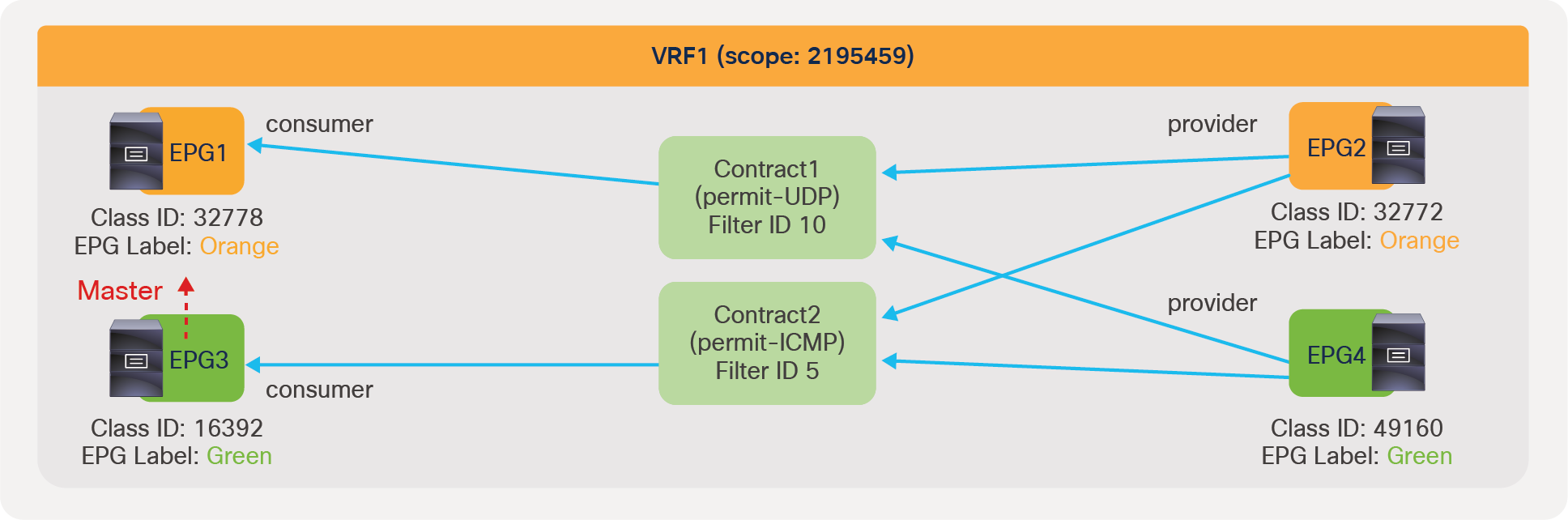
Labels with contract inheritance
Pod1-Leaf1# show zoning-rule scope 2195459
+---------+--------+--------+----------+----------------+---------+---------+-------------------+----------+----------------------+
| Rule ID | SrcEPG | DstEPG | FilterID | Dir | operSt | Scope | Name | Action | Priority |
+---------+--------+--------+----------+----------------+---------+---------+-------------------+----------+----------------------+
| 4246 | 32772 | 16392 | 10 | uni-dir-ignore | enabled | 2195459 | tenant1:Contract1 | permit | fully_qual(7) |
| 4247 | 32772 | 32778 | 10 | uni-dir-ignore | enabled | 2195459 | tenant1:Contract1 | permit | fully_qual(7) |
| 4175 | 16392 | 32772 | 10 | bi-dir | enabled | 2195459 | tenant1:Contract1 | permit | fully_qual(7) |
| 4251 | 32778 | 32772 | 10 | bi-dir | enabled | 2195459 | tenant1:Contract1 | permit | fully_qual(7) |
| 4206 | 16392 | 49160 | 5 | bi-dir | enabled | 2195459 | tenant1:Contract2 | permit | fully_qual(7) |
| 4231 | 49160 | 16392 | 5 | uni-dir-ignore | enabled | 2195459 | tenant1:Contract2 | permit | fully_qual(7) |
+---------+--------+--------+----------+----------------+---------+---------+-------------------+----------+----------------------+
The orange-highlighted lines (Rule ID 4246, 4247, 4175 and 4251) are created for UDP communication (FilterID: 10) between EPG1 and EPG2 that have “Orange” Label, and between EPG3 and EPG2 that is inherited from EPG1. Even though EPG3 has its own EPG Label “Green”, it’s not applied to Contract1. Thus, there is no permit rule with FilterID 10 between EPG3 and EPG4. The green-highlighted lines (Rule ID 4206 and 4231) are created for ICMP communication (FilterID: 5) between EPG3 and EPG4 that have “Green” Label. EPG3’s EPG Label “Green” is used for Contract2 that EPG3 is directly involved in.
Important points to consider about Labels are the following ones:
● Permit and deny actions can be used. Zoning-rules for a contract with service graph for copy and redirect actions are programmed regardless Label matching.
● Policy Compression doesn’t take effect on contracts that have Labels and or subject exceptions associated with them. Policy compression is implicitly enabled on the switches with High Policy profile except EX switches. This implies that contracts that have labels or subject exception don’t get the benefit of Policy compressions in the ACI fabric that contains the switches with High Policy profile except EXswitches.
● For consumer EPGs of inter-tenant contracts, Subject Labels at the imported contract in the consumer tenant are used to determine the matching instead of Subject Labels at the contract in the provider tenant. Other Labels: EPG Labels and Subject Labels at the consumer EPG and Contract Labels at the consumer EPG are not applicable.
● Labels can be used with contract inheritance. When EPG2 inherits a contract from EPG1(master), APIC uses the label configured under EPG1 for the contract inherited from EPG1. APIC uses the label configured under EPG2 for the contract where EPG2 is directly involved.
This section explains the microsegmentation capabilities in Cisco ACI. Cisco ACI has three types of microsegmentation features:
● Intra-EPG isolation: an EPG feature to drop traffic between endpoints in the same EPG
● Intra-EPG contract: the option to configure a contract for traffic between endpoints in the same EPG
● uSeg EPG (also called micro EPG): the ability to segment endpoints based on IP address, MAC address, or VM attributes (such as VM name) or with a combination of IP address, MAC address, and VM attributes
The type of microsegmentation features that you can configure depends on which type of “domain” (physical domain versus VMM domain, etc.) you are using. Table 5 provides the details of which feature can be used with which domain and which is the minimum release where that feature was introduced.
Table 5. Microsegmentation features and required Cisco ACI release
| Domain type |
Intra-EPG isolation |
Intra-EPG contract |
uSeg EPG |
Considerations |
| Physical domain |
Cisco ACI Release 1.2(2g) |
Cisco ACI Release 3.0 |
IP based EPG: Cisco ACI Release 1.2 MAC based EPG: Cisco ACI Release 2.1 |
IP-based EPG requires -E leaf or later uSeg attribute logical operator (AND/OR) requires Cisco ACI Release 2.3 or later |
| VMware vDS VMM domain |
Cisco ACI Release 1.2(2g) |
Cisco ACI Release 3.0 |
Cisco ACI Release 1.3 |
uSeg EPG requires -EX leaf or later uSeg attribute logical operator (AND/OR) requires Cisco ACI Release 2.3 or later |
| VMware AVE VMM domain (enterprise mode) |
Cisco ACI Release 3.1 VXLAN mode only |
Not supported |
Cisco ACI Release 3.1 |
AVE doesn’t enforce policy. Leaf enforces policy the same as with a vDS VMM domain. |
| VMware AVE VMM domain (cloud mode for vPod) |
Not supported |
Not supported |
Cisco ACI Release 4.0 |
|
| Microsoft SCVMM VMM domain |
Cisco ACI Release 3.0 |
Not supported |
Cisco ACI Release 1.2 |
Intra EPG isolation requires -EX leaf or later uSeg attribute Logical operator requires Cisco ACI Release 3.0 or later Custom attribute Cisco ACI Requires 3.2(2) |
Intra-EPG isolation can be configured at Tenant > Application Profiles > Application_Profile_name > Application EPGs > EPG_name > Policy > General. Default is “Unenforced.”
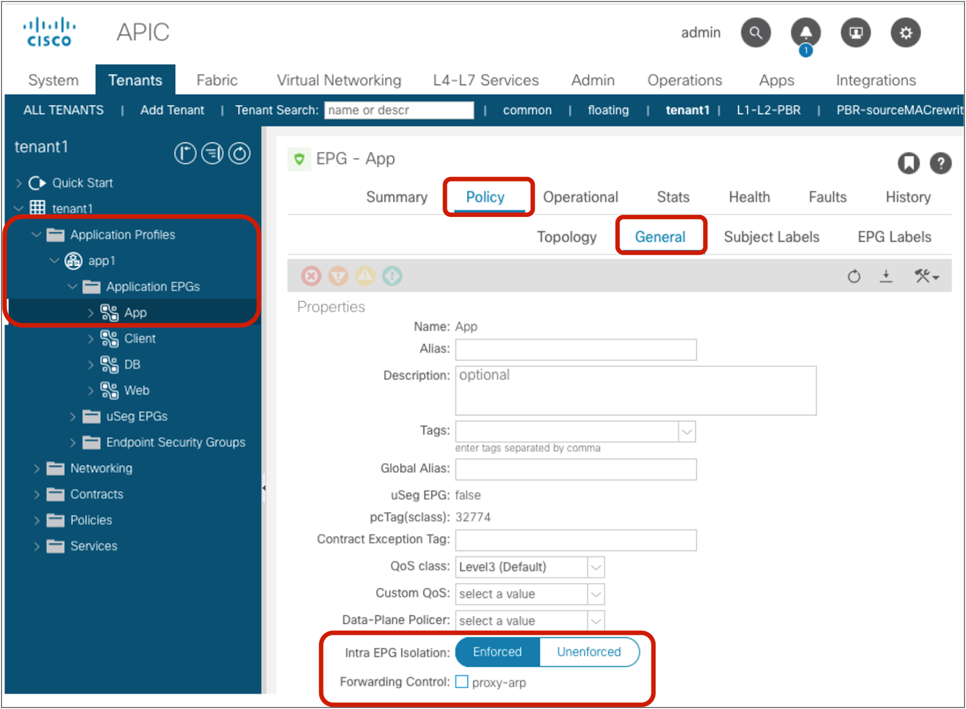
Intra EPG Isolation
Note: Once “Enforced” is checked, the “Forwarding control configuration” option “enable Proxy-ARP” shows up. Proxy-ARP must be enabled if communication between EPGs in the same bridge domain subnet is required for the EPG with intra-EPG isolation enabled. If Proxy-ARP is enabled, all communication is routed by the leaf even if source and destination endpoints are in the same bridge domain subnet.
Figure 71 and the CLI output from the “show zoning-rule” command, below the figure, illustrate an example of a policy programmed on a leaf for intra-EPG isolation.

Intra-EPG isolation example
Pod1-Leaf1# show zoning-rule scope 2850817
+---------+--------+--------+----------+----------------+---------+---------+-------------------+----------+----------------------+
| Rule ID | SrcEPG | DstEPG | FilterID | Dir | operSt | Scope | Name | Action | Priority |
+---------+--------+--------+----------+----------------+---------+---------+-------------------+----------+----------------------+
| 4250 | 0 | 0 | implicit | uni-dir | enabled | 2850817 | | deny,log | any_any_any(21) |
| 4246 | 0 | 0 | implarp | uni-dir | enabled | 2850817 | | permit | any_any_filter(17) |
| 4208 | 0 | 15 | implicit | uni-dir | enabled | 2850817 | | deny,log | any_vrf_any_deny(22) |
| 4247 | 0 | 32777 | implicit | uni-dir | enabled | 2850817 | | permit | any_dest_any(16) |
| 4231 | 32774 | 32774 | implicit | uni-dir | enabled | 2850817 | | deny,log | class-eq-deny(2) |
| 4244 | 32774 | 32775 | 68 | uni-dir-ignore | enabled | 2850817 | tenant1:Contract1 | permit | fully_qual(7) |
| 4222 | 32775 | 32774 | 67 | bi-dir | enabled | 2850817 | tenant1:Contract1 | permit | fully_qual(7) |
+---------+--------+--------+----------+----------------+---------+---------+-------------------+----------+----------------------+
The red-highlighted line (Rule ID 4231) is created because of intra EPG isolation at App EPG. Endpoints in App EPG can’t communicate with each other, but they can still communicate with an endpoint in Web EPG because of Contract1.
The following list includes some key design considerations for the use of intra-EPG isolation:
● In the case of a VMware vDS VMM and SCVMM domain:
◦ Once intra-EPG isolation is enabled, Cisco ACI programs PVLAN (Private VLAN) on the port-group for the EPG. If there is an intermediate switch, such as a Cisco UCS® fabric interconnect, between the ACI leaf and a vDS, you must configure PVLAN on the intermediate switch.
● If you require communication between EPGs that are in the same bridge domain subnet and configured with intra-EPG isolation, you need to manually enable proxy-ARP too.
● By enabling proxy-ARP, a VM (or, in general, an endpoint) that sends ARPs for another endpoint, receives an answer from the BD SVI that is the BD subnet IP owned by ACI leaf nodes; therefore, traffic between endpoints is routed.
Starting from APIC Release 5.2(1), intra-EPG isolation is available at L3Out EPG as well. Intra Ext-EPG isolation can be configured at Tenant > Networking > L3Outs > L3Out_name > External EPGs > L3Out_EPG_name > Policy > General. Default is “Unenforced.”
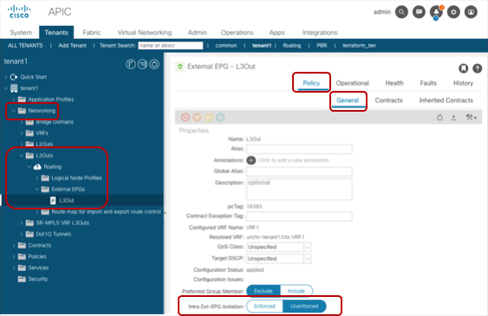
Intra Ext-EPG Isolation
Figure 73 and the CLI output from the “show zoning-rule” command, below the figure, illustrate an example of a policy programmed on a leaf for intra Ext-EPG isolation.
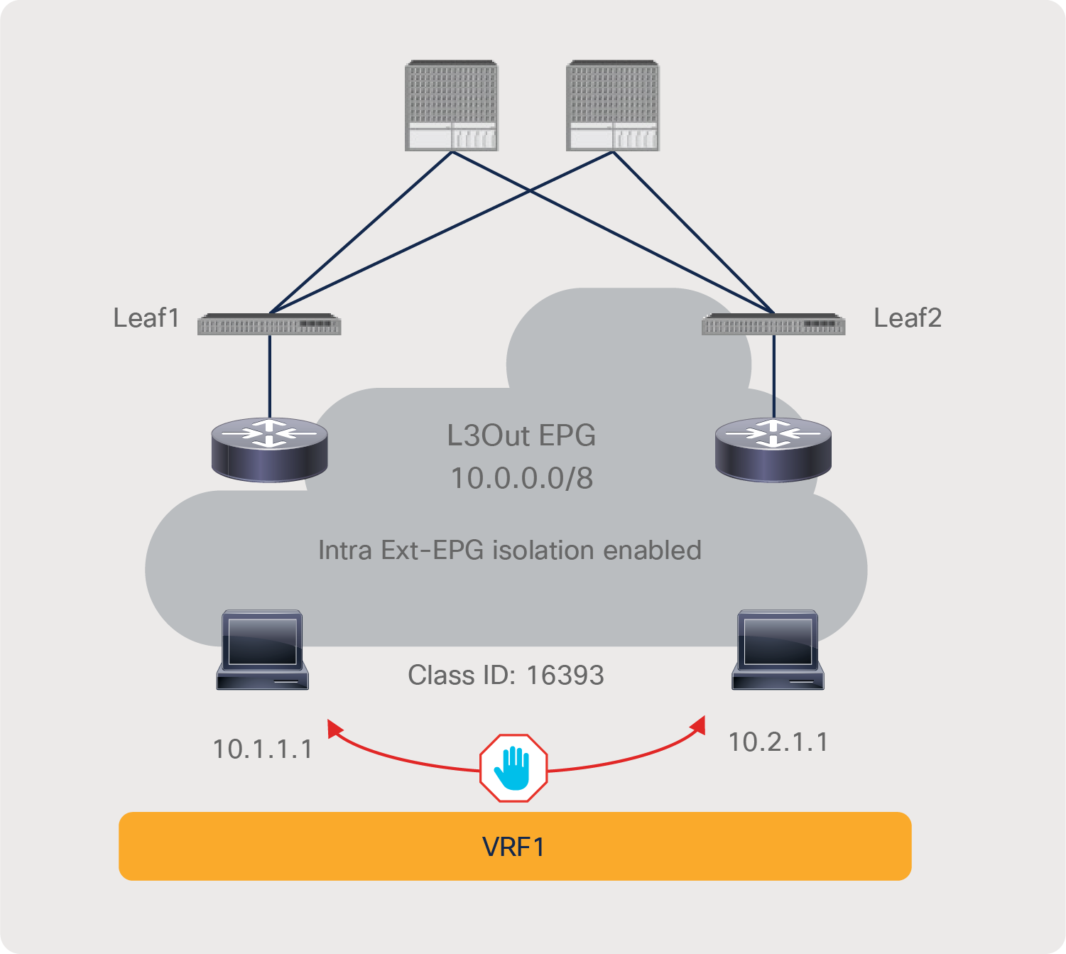
Intra-EPG isolation example
Pod1-Leaf1# show zoning-rule scope 2195459
+---------+--------+--------+----------+----------------+---------+---------+-------------------+----------+----------------------+
| Rule ID | SrcEPG | DstEPG | FilterID | Dir | operSt | Scope | Name | Action | Priority |
+---------+--------+--------+----------+----------------+---------+---------+-------------------+----------+----------------------+
| 4100 | 0 | 0 | implarp | uni-dir | enabled | 2195459 | | permit | any_any_filter(17) |
| 4098 | 0 | 49156 | implicit | uni-dir | enabled | 2195459 | | permit | any_dest_any(16) |
| 4101 | 0 | 15 | implicit | uni-dir | enabled | 2195459 | | deny,log | any_vrf_any_deny(22) |
| 4099 | 0 | 0 | implicit | uni-dir | enabled | 2195459 | | deny,log | any_any_any(21) |
| 4157 | 16393 | 16393 | implicit | uni-dir | enabled | 2195459 | | deny,log | class-eq-deny(2) |
+---------+--------+--------+----------+----------------+---------+---------+-------------------+----------+----------------------+
The red-highlighted line (Rule ID 4157) is created because of intra Ext-EPG isolation at the L3Out EPG.
The following list includes some key design considerations for the use of intra Ext-EPG isolation:
● L3Out EPG with 0.0.0.0/0 or 0::0 can’t use intra Ext-EPG isolation. This is because an L3Out EPG configured with a 0.0.0.0/0 subnet uses special class IDs. Please see L3Out EPG with 0.0.0.0/0 subnet for details. A workaround is to use multiple specific subnets, such as 0.0.0.0/1 and 128.0.0.0/1, for the L3Out EPG to catch all subnets.
● How traffic reaches the ACL border leaf for intra Ext-EPG security enforcement is outside of ACI’s control.
Whereas intra-EPG isolation denies all of the traffic within an EPG, an intra-EPG contract can specify which traffic is allowed within an EPG based on protocol, L4 ports, and so on. The intra-EPG contract supports permit, deny, redirect, copy, and Log actions the same as a contract between EPGs. Redirect and copy actions in an intra-EPG contract are supported from Cisco APIC Release 4.0.
The configuration for the intra-EPG contract is at Tenant > Application Profiles > Application_Profile_name > Application EPGs > EPG_name > Contracts.

Intra-EPG contract configuration
Figure 75 and the CLI output from the “show zoning-rule” command, below the figure, illustrate an example of a policy programmed on a leaf for an intra-EPG contract.
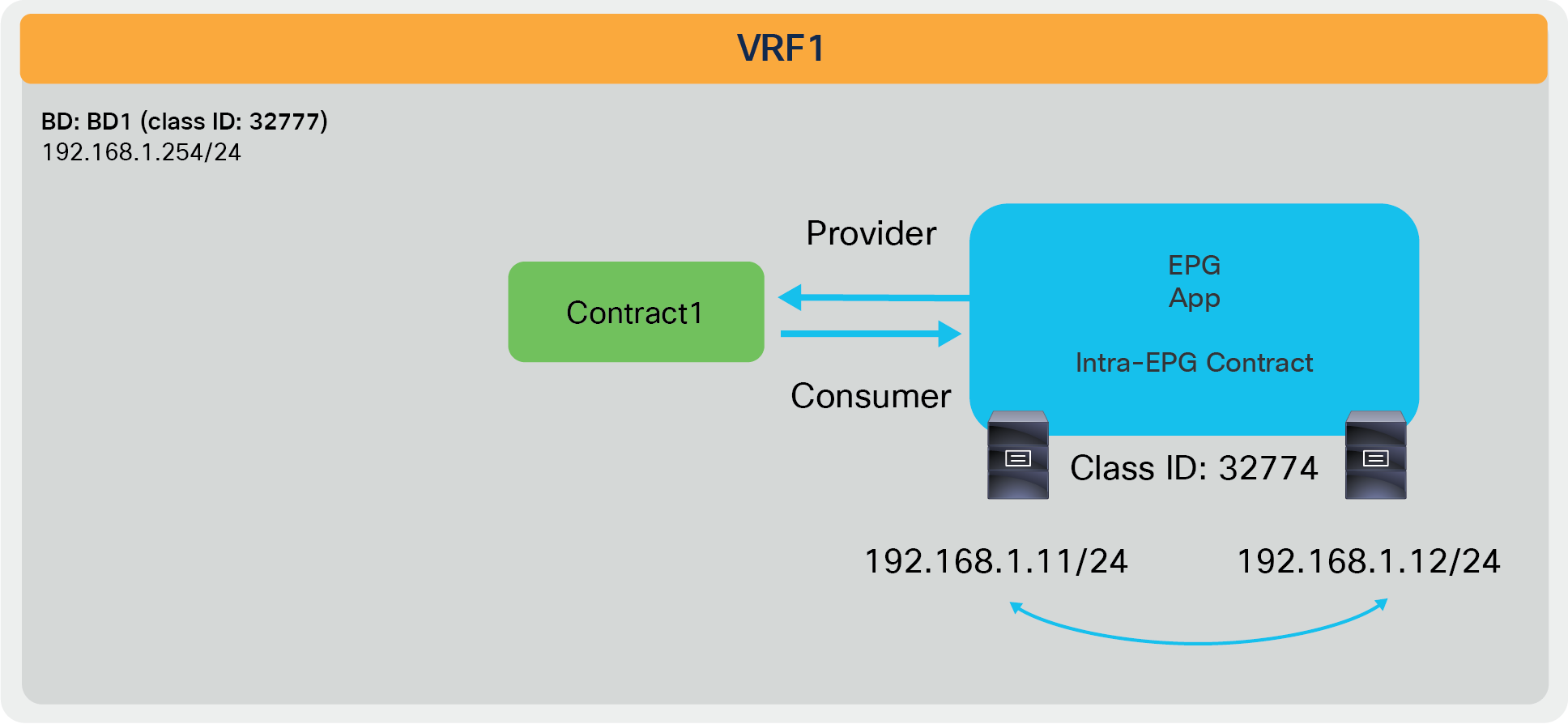
Intra-EPG contract example
Pod1-Leaf1# show zoning-rule scope 2850817
+---------+--------+--------+----------+----------------+---------+---------+-------------------+----------+----------------------+
| Rule ID | SrcEPG | DstEPG | FilterID | Dir | operSt | Scope | Name | Action | Priority |
+---------+--------+--------+----------+----------------+---------+---------+-------------------+----------+----------------------+
| 4250 | 0 | 0 | implicit | uni-dir | enabled | 2850817 | | deny,log | any_any_any(21) |
| 4246 | 0 | 0 | implarp | uni-dir | enabled | 2850817 | | permit | any_any_filter(17) |
| 4208 | 0 | 15 | implicit | uni-dir | enabled | 2850817 | | deny,log | any_vrf_any_deny(22) |
| 4247 | 0 | 32777 | implicit | uni-dir | enabled | 2850817 | | permit | any_dest_any(16) |
| 4231 | 32774 | 32774 | implicit | uni-dir | enabled | 2850817 | | deny,log | class-eq-deny(2) |
| 4222 | 32774 | 32774 | 68 | bi-dir | enabled | 2850817 | tenant1:Contract1 | permit | class-eq-filter(1) |
| 4244 | 32774 | 32774 | 67 | uni-dir-ignore | enabled | 2850817 | tenant1:Contract1 | permit | class-eq-filter(1) |
+---------+--------+--------+----------+----------------+---------+---------+-------------------+----------+----------------------+
The red-highlighted lines (Rule IDs 4231, 4222, and 4244) are created because of an intra-EPG contract at App EPG. Endpoints in App EPG cannot communicate with each other except for traffic permitted in the Contract1 subject.
As in intra-EPG isolation, with intra-EPG contract Cisco ACI programs PVLANs (Private VLANs) on the EPG port-group. ACI also programs proxy-ARP without the need for the administrator to do so. If there is an intermediate switch, such as a Cisco UCS fabric interconnect, that is in between an ACI leaf and a vDS, you must configure PVLANs on the intermediate switch.
Starting from APIC Release 5.2(1), intra-EPG contract is available at L3Out EPG as well. Intra Ext-EPG contract can be configured at Tenant > Networking > L3Outs > L3Out_name > External EPGs > L3Out_EPG_name > Policy > Contracts.
Intra Ext-EPG contract
Figure 77 and the CLI output from the “show zoning-rule” command, below the figure, illustrate an example of a policy programmed on a leaf for an intra Ext-EPG contract.
Intra-EPG contract example
Pod1-Leaf1# show zoning-rule scope 2195459
+---------+--------+--------+----------+----------------+---------+---------+-------------------+----------+----------------------+
| Rule ID | SrcEPG | DstEPG | FilterID | Dir | operSt | Scope | Name | Action | Priority |
+---------+--------+--------+----------+----------------+---------+---------+-------------------+----------+----------------------+
| 4100 | 0 | 0 | implarp | uni-dir | enabled | 2195459 | | permit | any_any_filter(17) |
| 4098 | 0 | 49156 | implicit | uni-dir | enabled | 2195459 | | permit | any_dest_any(16) |
| 4101 | 0 | 15 | implicit | uni-dir | enabled | 2195459 | | deny,log | any_vrf_any_deny(22) |
| 4099 | 0 | 0 | implicit | uni-dir | enabled | 2195459 | | deny,log | any_any_any(21) |
| 4163 | 16393 | 16393 | 8 | bi-dir | enabled | 2195459 | tenant1:Contract1 | permit | class-eq-filter(1) |
| 4156 | 16393 | 16393 | 9 | uni-dir-ignore | enabled | 2195459 | tenant1:Contract1 | permit | class-eq-filter(1) |
| 4157 | 16393 | 16393 | implicit | uni-dir | enabled | 2195459 | | deny,log | class-eq-deny(2) |
+---------+--------+--------+----------+----------------+---------+---------+-------------------+----------+----------------------+
The red-highlighted lines (Rule IDs 4163, 4156, and 4157) are created because of an intra Ext-EPG contract and intra Ext-EPG isolation at the L3Out EPG. Unlike intra-EPG contract on an EPG, an implicit deny rule (Rule ID 4157) is NOT automatically added in the case of intra Ext-EPG contract. Thus, Intra-EPG isolation needs to be enabled to deny other traffic.
The following list includes some key design considerations for the use of intra Ext-EPG isolation:
● L3Out EPG with 0.0.0.0/0 or 0::0 can’t use intra Ext-EPG contract. This is because an L3Out EPG configured with a 0.0.0.0/0 subnet uses special class IDs. Please see L3Out EPG with 0.0.0.0/0 subnet for detail. A workaround is to use multiple specific subnets, such as 0.0.0.0/1 and 128.0.0.0/1, for the L3Out EPG to catch all subnets.
● How traffic reaches the ACL border leaf for intra Ext-EPG security enforcement is outside of ACI’s control.
● Unlike intra-EPG contract on an EPG, an implicit deny rule is NOT automatically added in case of intra Ext-EPG contract. Intra-EPG isolation needs to be enabled to deny other traffic.
A uSeg EPG, also called a micro EPG, is an EPG that can provide more granular EPG classification. A uSeg EPG classifies endpoints of a given BD based on the IP/MAC address or VM attributes of the endpoints instead of the VLAN/VXLAN and interface.
Defining a uSeg EPG requires first the configuration of a regular EPG, which is referred to as a “base EPG.” The base EPG is what appears in a virtualized server as a port-group; this is the EPG to which you would attach the vNIC of virtual machines.
If you reclassify all the traffic into uSeg EPGs, you may wonder what is the purpose of having also configured a base EPG. The main purpose of the base EPG is the assignment of endpoints to a bridge domain. In fact, the uSeg EPGs must belong to the same bridge domain as the base EPG. You can define more than one base EPG for the same bridge domain if you so desire, and once endpoints are associated with the bridge domain, you can microsegment the BD with the uSeg EPGs. Which base EPG they came from is not relevant. You can also have a BD where some endpoints are part of the uSeg EPGs and other endpoints are part of the base EPG(s).
Figure 78 illustrates an example that uses one base EPG for the BD. Endpoints in VLAN 10 are classified to EPG1, which is the base EPG. Even though endpoints are in the same VLAN, endpoints matched with a uSeg EPG attribute can belong to the uSeg EPG2 instead of the base EPG1. If you change the uSeg EPG criteria in a way that the uSeg no longer has a match statement for 10.10.10.3, the endpoint in uSeg EPG disappears and is again part of the base EPG.
uSeg EPG
uSeg EPGs can match a variety of attributes, so if there are conflicting rules, Cisco ACI uses a specific order of priority to classify endpoints into a uSeg EPG. Table 6 lists the priorities associated with each attribute.
Table 6. uSeg attribute preference
| Attribute type |
Precedence |
Operator |
Example |
Consideration |
| MAC address* |
1 |
Equals |
00:25:B5:00:00:01 |
|
| IP address* |
2 |
Equals |
192.168.1.1 192.168.2.0/24 2001:db8:cafe:1:403e:6bff: 71e9:70f0 2001:db8:cafe:1::/64 |
|
| VM – VNic Dn |
3 |
Equals, Contains, Ends with, Starts with |
00:50:56:11:11:11 |
|
| VM – VM identifier |
4 |
Equals, Contains, Ends with, Starts with |
vm-598 |
|
| VM – VM name |
5 |
Equals, Contains, Ends with, Starts with |
Prod-Web-VM-01 |
|
| VM – hypervisor identifier |
6 |
Equals, Contains, Ends with, Starts with |
host-03 |
|
| VM – VMM domain |
7 |
Equals, Contains, Ends with, Starts with |
DVS-SJC-DC1 |
|
| VM – data center |
8 |
Equals, Contains, Ends with, Starts with |
SJC-DC1 |
|
| VM – custom attribute |
9 |
Equals, Contains, Ends with, Starts with |
Attribute: ACME Value: Prod-Web |
|
| VM – operating system |
10 |
Equals, Contains, Ends with, Starts with |
Windows 2016 |
|
| VM – tag |
11 |
Equals, Contains, Ends with, Starts with |
Category: ACME Tag: Prod-Web |
Available from Cisco APIC Release 2.3. VMware VMM domain only |
| DNS (beta) |
12 |
Equals |
web1.example.com |
Beta available from Cisco APIC Release 2.3. |
| AD group (beta) |
13 |
Equals |
Users/Eng/Eng-1 |
Beta available from Cisco APIC Release 3.2.2. Cisco Identity Services Engine (ISE) is required. |
| VM – VM folder (beta) |
14 |
Equals, Contains, Ends with, Starts with |
Prod-folder |
Beta available from Cisco APIC Release 3.2. VMware VMM domain only |
| VM – VM folder path (beta) |
15 |
Equals, Contains, Ends with, Starts with |
Prod-folder/Web |
Beta available from Cisco APIC Release 4.2. VMware VMM domain only |
The uSeg EPG configuration location is at Tenant > Application Profiles > Application_Profile_name > uSeg EPGs > EPG_name. uSeg EPG requires a domain association, as shown in Figure 79. In the case of physical domains, a “Static Leafs” configuration under the uSeg EPG is also required, to indicate to which leaf it should be provisioned. This is in addition to the Base EPG Static Port Configuration (which already includes the information about leaf nodes). This is because a base EPG and uSeg EPGs for physical domains are managed as independent entities in ACI.

Configure uSeg EPG domain association
uSeg attributes can be set at uSeg Attributes under the uSeg EPG. uSeg attribute matching conditions can be match-Any (OR) or match-All (AND), as you can see in Figure 80.
Configure uSeg EPG attributes
If you are using a VMware vDS VMM domain, you must check “Allow Micro-Segmentation” at the base EPG. That configures PVLAN (Private VLAN) on the port-group for the base EPG, and it enables proxy-ARP within the base EPG. “Allow Micro-Segmentation” is not checked by default. Figure 81 shows the configuration. By default, VLAN IDs for primary VLAN and secondary VLAN (Port Encap on the GUI) are dynamically allocated from a dynamic VLAN range in the VLAN pool associated to the VMM domain. VLAN IDs can be statically allocated from a static VLAN range in the VLAN pool associated to the VMM domain.
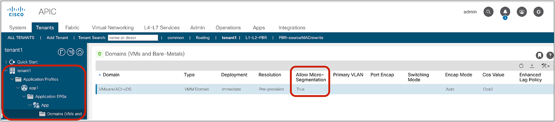
“Allow Micro-Segmentation” must be enabled in the base EPG for VMware vDS VMM domain
With “Allow Micro-Segmentation” checked for a VMM domain, the base EPG classification changes from VLAN-based to MAC-based; this is because there could be more than one VM in the same VLAN, and these VMs may belong to separate uSeg EPGs. If, for some reason, traffic is incorrectly classified based on VLANs instead of MAC, Cisco ACI assigns this traffic to class ID 10.
If “Allow Micro-Segmentation” is enabled on an EPG with a VMware vDS VMM domain, two implicit deny rules are created in order to drop traffic that has been incorrectly classified. The following “show zoning-rule” output shows an example:
Pod1-Leaf1# show zoning-rule scope 2850817
+---------+--------+--------+----------+---------+---------+---------+------+----------+----------------------+
| Rule ID | SrcEPG | DstEPG | FilterID | Dir | operSt | Scope | Name | Action | Priority |
+---------+--------+--------+----------+---------+---------+---------+------+----------+----------------------+
| 4211 | 0 | 16386 | implicit | uni-dir | enabled | 2850817 | | permit | any_dest_any(16) |
| 4208 | 0 | 0 | implicit | uni-dir | enabled | 2850817 | | deny,log | any_any_any(21) |
| 4222 | 0 | 0 | implarp | uni-dir | enabled | 2850817 | | permit | any_any_filter(17) |
| 4221 | 0 | 15 | implicit | uni-dir | enabled | 2850817 | | deny,log | any_vrf_any_deny(22) |
| 4254 | 0 | 32773 | implicit | uni-dir | enabled | 2850817 | | permit | any_dest_any(16) |
| 4215 | 10 | 0 | implicit | uni-dir | enabled | 2850817 | | deny,log | class-eq-deny(2) |
| 4251 | 0 | 10 | implicit | uni-dir | enabled | 2850817 | | deny,log | class-eq-deny(2) |
+---------+--------+--------+----------+---------+---------+---------+------+----------+----------------------+
The red-highlighted rules are created because of “Allow Micro-Segmentation” on an EPG with VMware vDS VMM domain.
As in any EPG, uSeg EPGs also have a unique class ID that is used in zoning-rules. An endpoint matched with a uSeg EPG attribute is classified to the uSeg EPG, and contract security is enforced based on the uSeg EPG class ID instead of the base EPG class ID.

uSeg EPG class ID
Resolution and deployment immediacy work slightly differently on uSeg EPGs compared to base EPGs, which also work differently depending on the domain type. In summary, resolution immediacy (when VRF, bridge domains, and SVIs are programmed on the leaf nodes) is not user-configurable for a uSeg EPG because these network-related configurations are already taken care by the existence of base EPGs, and deployment immediacy (when contract policies are programmed on the leaf nodes) depends on the user configuration on a uSeg EPG.
In physical domains:
● When deploying uSeg EPG workloads that belong to a physical domain, the configuration of the uSeg EPG must include the information of the “Static Leafs” as shown in Figure 79.
● The resolution immediacy of the base EPG is not applicable to the physical domain because network-related configurations are programmed based on a “Static Ports” or “Static Leafs” configuration, thus it’s not configurable by the user.
● The deployment immediacy of the base EPG is set at “Static Ports” under the base EPG.
● The resolution immediacy of the uSeg EPG is not applicable to the physical domain, thus it’s not user configurable. The policies related to the uSeg EPG are downloaded to a leaf if at least one base EPG in the same bridge domain is downloaded to the leaf. Under the uSeg EPG configuration, you need to define the static leaf mappings (see Figure 78), which tells ACI on which leaf the policies related to the uSeg EPG should be programmed.
● The deployment immediacy of the uSeg EPG is not configurable as of Cisco ACI Release 5.1.3. As the first bullet says, uSeg EPGs in physical domains require the configuration of “Static Leafs” (that is, the leaf nodes on which the uSeg EPG must be programmed), and the deployment immediacy is automatically set as “Immediate” as part of the “Static Leaf” configuration.
In VMware vDS VMM domains:
● When deploying uSeg EPG for workloads that are part of a VMM domain, the administrator doesn’t need to specify manually on which leaf nodes uSeg EPG should be deployed, as shown in Figure 78; this action is automated.
● The resolution-immediacy configuration of the base EPG and the uSeg EPG set by the user is not used; instead, ACI sets it automatically to “immediate,” but the implementation of the “immediate” option is slightly different from how “immediate” works for other EPG types:
◦ If “Allow Micro-Segmentation” is set to “True,” the resolution immediacy of the base EPG becomes “Immediate” internally regardless of the resolution immediacy configuration of the base EPG. This means that the policies related to the base EPG are downloaded to a leaf when an ESXi host is attached to the vDS and CDP/LLDP (Cisco Discovery Protocol / Link Layer Discovery Protocol) neighborship is established between the ESXi host and the leaf.
◦ The policies related to the uSeg EPG are downloaded to all of the leaf nodes that have CDP/LLDP neighborship with an ESXi host attached to the vDS if at least one virtual machine vNIC is associated with a base EPG in the same BD with the uSeg EPG. The difference between this behavior and the behavior with “Immediate” is that the policies are NOT downloaded to a leaf until at least one virtual machine vNIC is associated with a base EPG in the same BD with the uSeg EPG. This behavior is not exactly same as “On-Demand” either because the policies are downloaded to all leaf nodes that have CDP/LLDP neighborship with an ESXi host attached to the vDS even if no virtual machine vNIC is connected to each leaf.*
◦ Prior to Cisco APIC Release 5.0, if the resolution immediacy of the uSeg EPG is “On Demand,” internally APIC will set it as “Immediate.” If the deployment immediacy of the uSeg EPG is “On Demand,” APIC rejects it.
◦ Starting from Cisco APIC Release 5.1, the resolution immediacy configuration of the base EPG with VMM domain is grayed out if “Allow Micro-Segmentation” is set to “True.” The resolution immediacy configuration of the uSeg EPG with VMM domain is also grayed out. This is because the resolution immediacy configuration of the base EPG and the uSeg EPG set by the user are not used.
● The deployment immediacy is user-configurable on a base EPG and a uSeg EPG with a VMM domain; this option optimizes contracts programming. If you want to minimize traffic downtime because of the policy deployment during a new attachment, such as vMotion, the deployment immediacy should be “Immediate.”
● The deployment immediacy of base EPGs works as described in the next bullets:
◦ If the deployment immediacy of the base EPG is “Immediate,”, the policies related to the base EPG are programmed on a leaf once the policies are pushed to the leaf. This means that, when a VMM domain association with “Allow Micro-segmentation” is added to the base EPG, the policies are programmed on the leaf, because the resolution immediacy for base EPGs with a vDS VMM domain is always “Immediate” if “Allow Micro-Segmentation” is set to “True.”
◦ If the deployment immediacy of the base EPG is “On Demand,” the following happens. Cisco ACI deploys contracts for all base EPGs sharing the same PVLAN pair as soon as the first endpoint is learned in any of the base EPGs configured for “On Demand” deployment. (All base EPGs, with “Allow Micro-Segmentation” enabled, associated with the same BD and VMM domain share the same PVLAN pair.) In short, once a leaf receives a packet that is from any of the base EPG regardless of the endpoint is classified to a uSeg EPG or not, the policies related to the base EPG are programmed on the leaf, but also the policies related to the other base EPGs in the same BD.
● The deployment immediacy of uSeg EPGs works as described in the next bullets:
◦ If the deployment immediacy of the uSeg EPG is “Immediate,” the policies related to the uSeg EPG are programmed on a leaf once the policies are pushed to the leaf.
◦ If the deployment immediacy of the uSeg EPG is “On Demand,” the policies related to the uSeg EPG are programmed on a leaf once the leaf learns the first endpoint in the uSeg EPG.
The following is a list of uSeg EPG configuration-and-design points to keep in mind:
● uSeg EPG requires “Ingress” enforcement mode on the VRF
● The uSeg EPG domain must be configured to match the base EPG domain.
● Base EPG(s) and uSeg EPG(s) must be in the same BD, and the BD must have an IP subnet.
● uSeg EPG is also part of vzAny and supports preferred group, intra-EPG isolation, intra-EPG contract, and other configurations per EPG.
● The use of logical operators (Match-Any/Match-All) for the uSeg attribute is supported since Cisco APIC Release 2.3.
● In physical domains and VMware vDS VMM domains, there is no precedence between MAC-based EPG and IP-based EPG. MAC-based EPG is used for bridged traffic, and IP-based EPG is used for IP traffic.
● In a VMware vDS VMM domain, “Allow Micro-Segmentation” must be checked at the base EPG (this automatically configures Private VLANs on the port-group for the base EPG and proxy-ARP within the base EPG).
● In a physical domain, proxy-ARP is NOT always enabled. Without proxy-ARP, traffic between endpoints in the same subnet in the same base EPG is a bridged traffic for ACI fabric, which means source and destination EPG classifications are based on MAC address (MAC-based uSeg EPG), or leaf interface and VLAN ID (base EPG). If IP-based uSeg EPG classification is needed for such traffic, proxy-ARP needs to be enabled on the base EPG. The options to enable proxy-ARP on a base EPG with a physical domain are as follows:
◦ Configure intra-EPG contract on the base EPG.
◦ Enable proxy-ARP along with intra-EPG isolation on the base EPG.
The former would be more practical than the latter unless complete isolation is required within the base EPG.
● In a physical domain, under the uSeg EPG configuration, you need to define the static-leaf mappings (see Figure 78), which tells ACI on which leaf the policies related to the uSeg EPG should be programmed.
● Because PVLAN is used for uSeg EPG, if there is an intermediate switch, such as a Cisco UCS fabric interconnect, between an ACI leaf and endpoints, PVLAN must be configured at the intermediate switch. In such a case, the use of static VLAN allocation would be practical even for a VMM domain to use the same PVLAN configuration on both the ACI fabric and the intermediate switch.
● Custom QoS and QoS class configurations at uSeg EPGs are not supported. Custom QoS and QoS class configurations at base EPGs are supported unless intra-EPG isolation or intra-EPG contract is enabled on the base EPG.
Endpoint Security Groups are an evolution of the EPG and microsegmentation concepts. This feature has been introduced in Cisco ACI Release 5.0 and requires -EX leaf nodes or newer. ESGs are a security zone but, differently from EPGs, ESGs are not bound to a bridge domain; instead, they are a security zone that works across the entire VRF. ESGs differ from EPGs also because ESGs are only a security zone; they do not have network-related configurations (such as subnets). The security rules are defined by using contracts between ESGs.
The example in Figure 83 helps to clarify. Imagine that web servers are in two different bridge domains and that application servers are also in two different bridge domains (Figure 83-a). Imagine that you need to configure security rules to allow web servers to talk to application servers. If each security zone (Web and App) can be in two different subnets or Layer 2 domains, you would have to configure four EPGs: EPG1-1 for the Web servers in BD1, EPG1-2 for the Web servers in BD2, EPG2-3 for the App servers in BD3, EPG2-4 for the App servers in BD4, and the configuration would require four to six contracts (Figure 83-b): four contracts if you just want to enable Web servers to talk to the App servers, six contracts if you also want to enable communication between the Web EPGs (and, similarly, between the App EPGs). But, with ESGs, you need to configure only two ESGs (Figure 83-c) and one contract. If you define another ESG for shared services, this ESG is also available for any bridge domain under the same VRF.
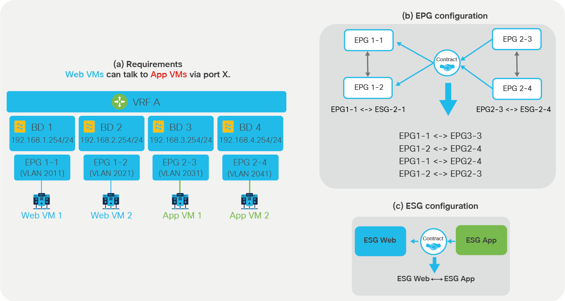
ESGs simplify the security configuration
With ESGs you can simplify the security configuration by moving the contracts configuration to the ESGs instead of to the EPGs. ESGs don’t replace EPGs, because you would still use EPGs to define how endpoints map to a bridge domain. In a network where you use ESGs for security rules, the EPGs configuration would still be used for the following configurations:
● Associating physical endpoints to the bridge domain with static binding.
● Associating virtual endpoints to the bridge domain with the VMM domain association.
● L3Out EPG (L3InstP) is still used to classify the external traffic.
For the outside to ACI traffic, you would use a contract between the L3Out EPG and the ESG, but contracts between ESGs and EPGs are not possible.
The classification of the endpoints in ESGs is similar to the uSeg EPG configuration. As of Cisco APIC Release 5.0, the only classification criteria are based on matching the IP address of the endpoint. For example, the user can enter a specific IP (/32, /128, or without a subnet mask) or a subnet match with any mask length. Future releases will add more classification options.
The configuration of the ESG is performed at Tenant > Application Profiles > Endpoint Security Groups.
For VRF-sharing purposes, route-leaking with ESGs is configured at the VRF level by entering which bridge domain subnet should be leaked and to which tenant and VRF it should be leaked to. This makes the VRF-sharing configuration more flexible because there is no need to map ESGs to subnets.
The configuration is performed at Tenant > Networking > VRFs > VRF_name > Inter- VRF Leaked Routes for ESG > Configure EPG/BD Subnets.
The following list provides a summary of which commonly used EPG features are equally applicable and available with ESGs:
● Preferred groups
● vzAny
● Service Graph with PBR
As of Cisco APIC Release 5.2(4), the following ESG selectors are available:
● Tag selector: Matches endpoints based on policy tags that are assigned to a variety of attributes such as MAC and IP addresses, Virtual Machine (VM) tags, virtual machine names (vm name), subnet tags, and static endpoint tags.
● EPG selector: Matches all endpoints in a specific EPG, and the ESG will inherit all contracts configured under the EPG.
● IP Subnet selector: Matches endpoints based on subnets or host IP address directly.
● Service EPG selector: Matches all endpoints in a specific service EPG that is created through a service graph deployment, and the ESG replaces the service EPG in zoning-rules.
As of Cisco APIC Release 5.2, the following limitations apply:
● An ESG contract can be applied only for routed traffic if IP Based selectors such as IP Subnet selector or Tag selector matching policy tags for subnets.
● Contract between ESGs and EPGs are not supported. Instead, by using EPG selector, endpoints in an EPG can be mapped to an ESG that inherits the contracts currently configured in the original EPG.
● Taboo contracts are not implemented with ESGs.
● Inter-VRF service graphs between ESGs are not yet implemented.
● The ESG feature is not integrated with Cisco ACI Multi-Site Orchestrator.
● ESGs do not work on first-generation leaf nodes (Cisco Nexus® 9396PX Switch, Cisco Nexus 93128TX Switch and so on).
For more information, please refer to this link: https://www.cisco.com/c/en/us/td/docs/dcn/aci/apic/5x/security-configuration/cisco-apic-security-configuration-guide-release-52x/m-endpoint-security-groups.html
Contract configuration options
This section explains the following configuration options for contracts, contract subjects or filters:
● Per-contract configurations:
◦ Scope (Please also see the “Inter-VRF and inter-tenant contracts” section.)
◦ QoS Class
◦ Target DSCP (This works only if the QoS class is set.)
● Contract subject configurations for the contract:
◦ Apply Both Directions and Reverse Filter Ports
◦ L4-L7 Service Graph
◦ QoS Priority
◦ Target DSCP (This works only if the QoS priority is set, or if the QoS class is set on the contract.)
◦ WAN SLA policy (For Cisco SD-WAN integration)
● Filter configurations for the contract subject:
◦ Deny action
◦ Log
◦ Enable Policy Compression
In Cisco ACI, QoS configurations are very much related to the EPG and contract configurations. The next section summarizes the key concepts about QoS in ACI in order to understand the configurations that follow.
QoS configurations
You might notice that QoS and DSCP (Differentiated Services Code Point) configurations are in multiple locations. The QoS-related configurations can be found in the EPG, in the contract, and in the contract subject.
As with normal QoS, QoS in ACI deals with class and marking to place traffic into one of the QoS classes. Each QoS class represents a class of service and is equivalent to a “qos-group” in traditional Cisco NX-OS. Each class of service maps to a queue or a set of queues in hardware.
The QoS configuration at the contract and the contract subject specifies the assignment of the traffic to a given qos-group (QoS class) based on the source EPG, destination EPG, and filters. The custom QoS configuration at the EPG specifies the assignment of the traffic to a given qos-group based on the dot1p or DSCP values of the incoming traffic from that EPG. The QoS class configuration at the EPG defines which qos-group based on the traffic from that to which the EPG belongs if none of the other previous criteria are matched.
Figure 84 illustrates the purpose of QoS Class configuration at the EPG versus a Custom QoS configuration at the EPG versus a QoS configuration in the contract and the contract subject, and in which order they are looked up. Notice that a Custom QoS at the EPG can be used not just to classify traffic into a qos-group but also to rewrite the DSCP value (this is called “Target DSCP”) of the payload packet.
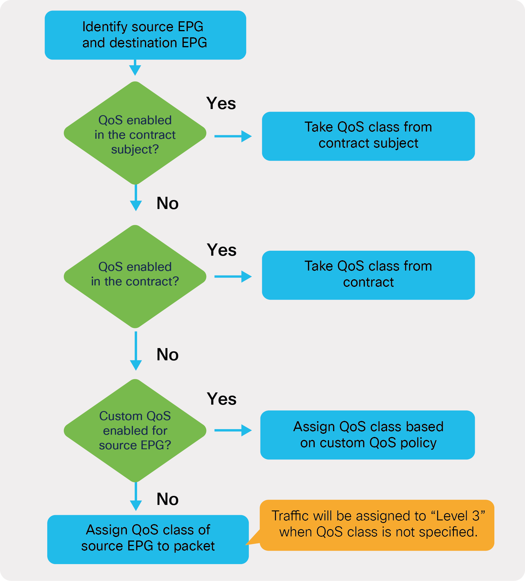
QoS configuration priority
In addition to this, at the contract level you can also configure QoS Class (using the same configuration name as the EPG) and Target DSCP (using the same name as the configuration under the Custom QoS in the EPG).
You can also assign traffic to a qos-group by configuring the QoS priority in the contract subject; also, you can rewrite the DSCP value (“Target DSCP”) at the contract-subject level.
The general rule is that the subject classification (or rewrite) configuration takes priority over the contract classification (or rewrite), which has priority over the Custom QoS configuration at the EPG; this, in turn, has priority over the EPG QoS Class configuration.
The contract configuration location is at Tenant > Contract > Contract_name.
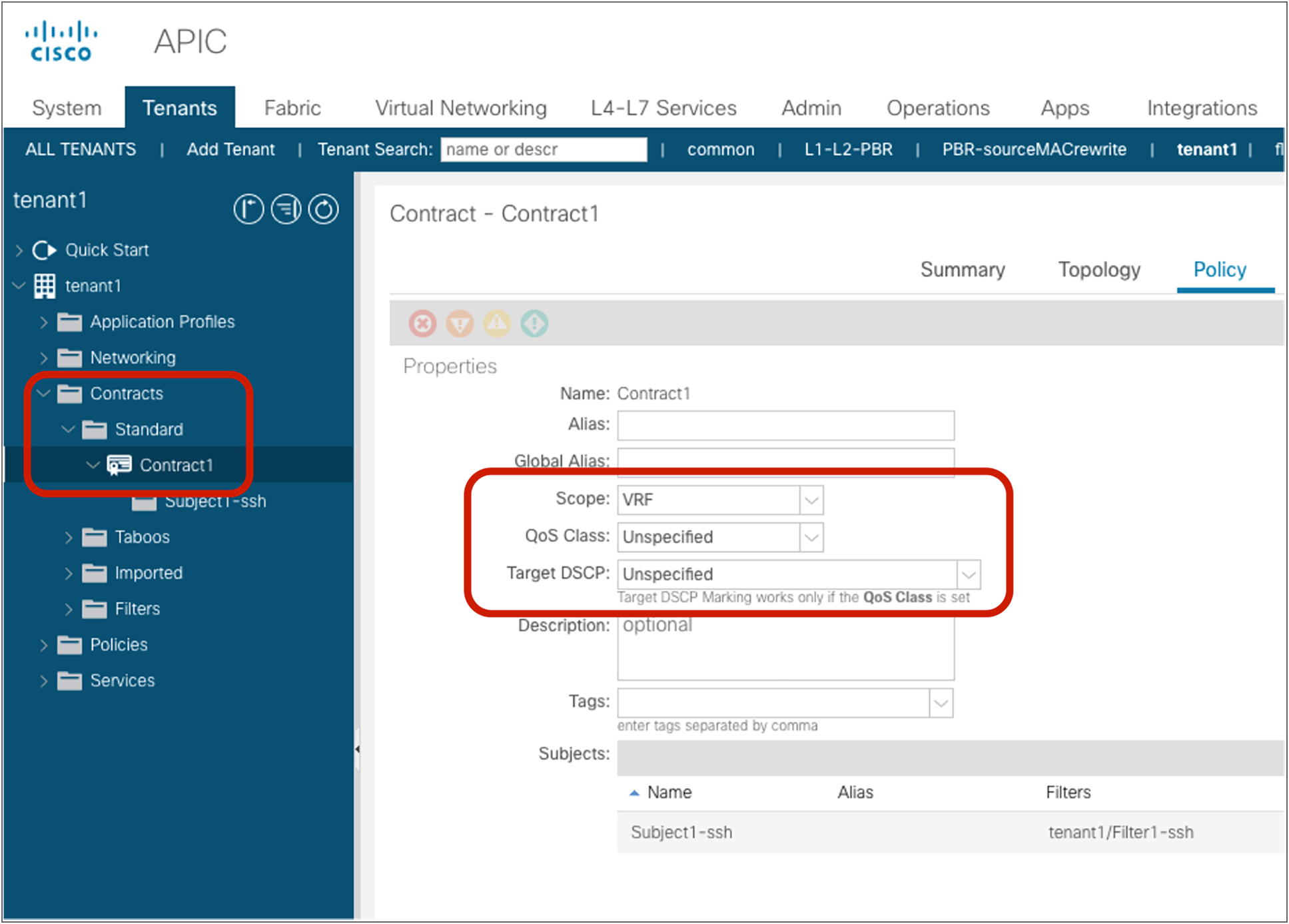
Contract configuration
This is an option to specify how widely the contract policy should be applied. The default configuration is “VRF.” Please see the “Contract scope” section for details.
QoS Class is an option to specify the class of service of the traffic matched with the contract. The default configuration is “Unspecified.” “Unspecified” is mapped to Cisco ACI QoS Level 3. ACI supports six user-configurable classes. Other classes are reserved for system-related traffic types: APIC traffic, SPAN traffic, SUP control traffic, traceroute, and copy service.
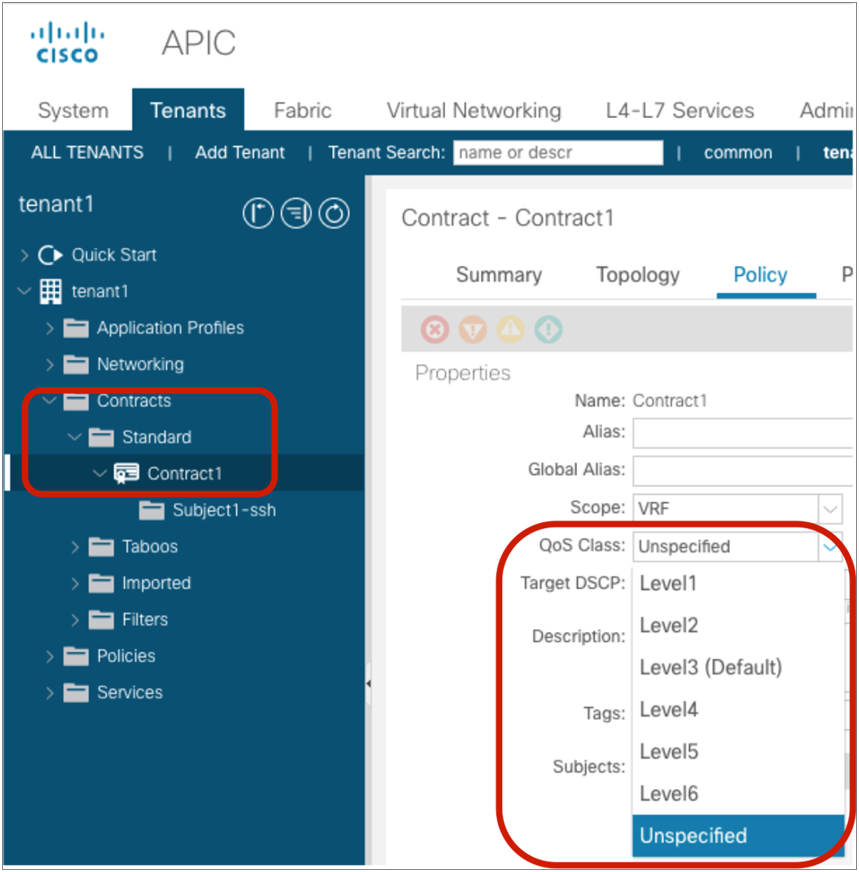
QoS Class configuration at contract
Note: Level 4, 5, and 6 requires an ACI fabric made up of Cisco Nexus 9000 EX/FX leaf and spine switches or later after Cisco APIC Release 4.0. If the ACI fabric has a mix of EX/FX switches along with older switches, Level 4—6 traffic received on the older switches will be mapped to Level 3.
Each class of service can be configured with various options at a system level. The configuration location is at Fabric > Access policies > Policies > Global > QoS Class.
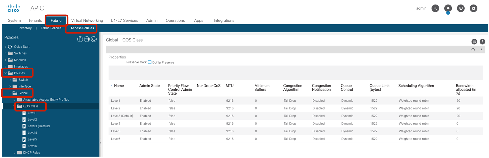
QoS Class configuration
The user can configure up to five strict-priority classes. The traffic will be prioritized in the fabric at each switch as below:
● Level 6
● Level 5
● Level 4
● Level 2
● Level 1
● Level 3
The QoS class can be configured in the contract subject, in the contract, in the EPG, and in the L3Out logical interface profile. The QoS policy is applied using the following precedence (please also refer to Figure 84):
1. QoS priority at contract subject: This is applied to traffic based on the contract subject.
2. QoS class at contract: This is applied to traffic based on the contract.
3. If the source EPG is non-L3Out EPG:
1. Custom QoS policy at source EPG: This is applied to traffic based on the source EPG, and DSCP or 802.1p.
2. QoS class at source EPG: This is applied to traffic based on the source EPG.
If the source EPG is L3Out EPG:
1. Custom QoS policy at L3Out logical interface profile: This is applied to traffic coming into the ACI fabric through the L3Out interface.
2. QoS Priority at L3Out logical interface profile: This is applied to traffic coming into the ACI fabric through the L3Out interface.
4. If no QoS class is specified, the traffic is assigned to Level 3 QoS class.
Note: QoS configurations on an L3Out EPG and L3Out logical interface profile only take effect for ingress traffic. For egress traffic, you should use QoS priority at contract subject or QoS class at contract to modify CoS of traffic. For L3Out, QoS configuration via contracts requires enforcement on the border leaf, which requires “Egress” enforcement mode on the VRF. (Policy Control Enforcement Direction must be “Egress.”)
Custom QoS and QoS class configuration at EPG is at Tenant > Application Profiles > Application_Profile_name > Application EPGs > EPG_name > Policy > General.
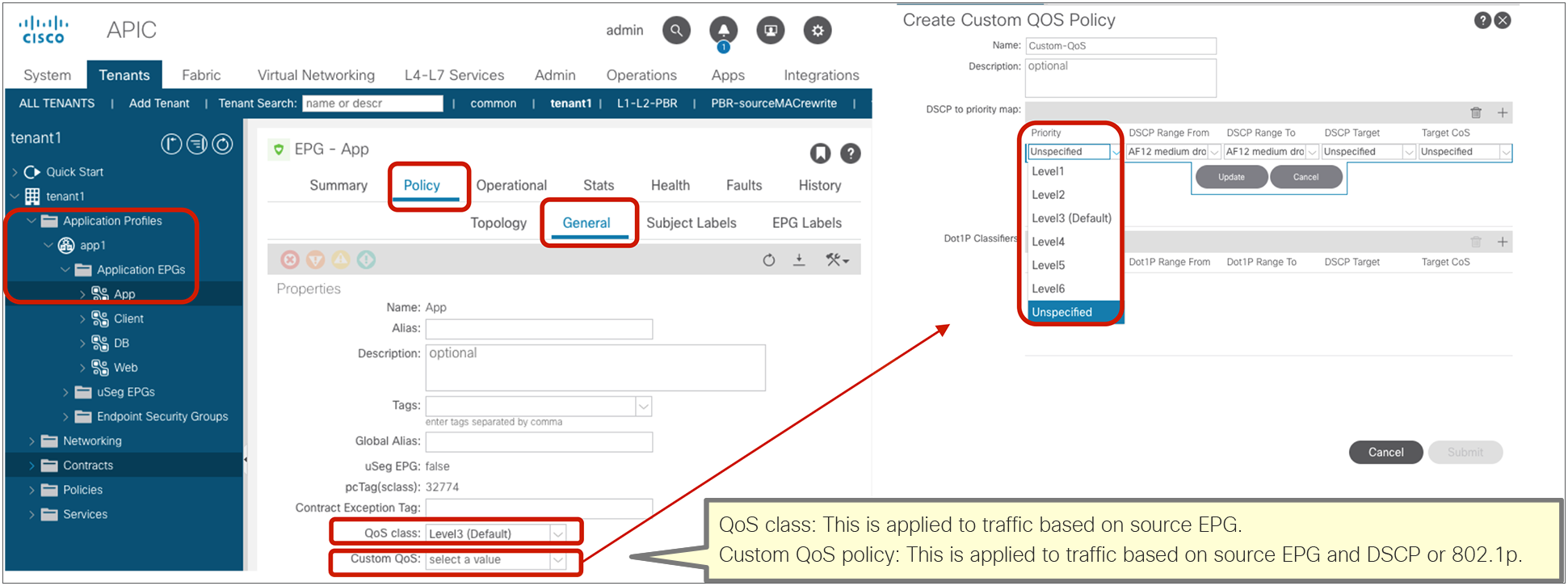
Note: Custom QoS and QoS class configurations at uSeg EPGs are not supported. Custom QoS and QoS class configurations at base EPGs are supported unless intra-EPG isolation or intra-EPG contract is enabled on the base EPG.
QoS configuration at EPG (Custom QoS policy and QoS class at source EPG)
In the case of the L3Out, the QoS configuration is at the L3Out EPG and the L3Out logical interface profile. The QoS configuration at the L3Out logical interface profile was introduced in Cisco APIC Release 4.0.
● The QoS Class (QoS Priority) and Custom QoS configuration for L3Out logical interfaces is at Tenant > Networking > L3Outs > L3Out_name > Logical Node Profiles > Logical_Node_Profile_name > Logical Interface Profiles > Logical_Interface_Profile_name > Policy > General.
● The QoS Class configuration location for the L3Out EPG is at Tenant > Networking > L3Outs > L3Out_name > External EPGs > External_EPG_name > Policy > General.

QoS configuration at L3Out (QoS Class at L3Out EPG, and QoS Class and Custom QoS at L3Out logical interface profile)
Note: After Cisco APIC Release 4.0, the use of Custom QoS policy at the L3Out logical interface profile is recommended for L3Out QoS.
Target DCSP
This is an option to rewrite the DSCP (Differentiated Services Code Point) priority in the traffic matched with the contract. The default configuration is “Unspecified.” To use this option, you must specify “QoS Class” option in the contract instead of “Unspecified.”
The supported DSCP priorities are the following:
● AF11 low drop
● AF12 medium drop
● AF13 high drop
● AF21 low drop
● AF22 medium drop
● AF23 high drop
● AF31 low drop
● AF32 medium drop
● AF33 high drop
● AF41 low drop
● AF42 medium drop
● AF43 high drop
● CS0 (class of service level 0)
● CS1 (class of service level 1)
● CS2 (class of service level 2)
● CS3 (class of service level 3)
● CS4 (class of service level 4)
● CS5 (class of service level 5)
● CS6 (class of service level 6)
● CS7 (class of service level 7)
● Expedited Forwarding (EF)
● Voice Admit
● Unspecified
Target DSCP can be configured in the contract subject, in the contract, in the EPG, and in the L3Out logical interface profile. The policy to rewrite the DSCP is applied using the following precedence:
1. Target DSCP at contract subject: The policy is applied to traffic based on the contract subject.
2. Target DSCP at contract: The policy is applied to traffic based on the contract.
3. If the source EPG is non-L3Out EPG:
◦ Custom QoS policy at source EPG: The policy is applied to traffic based on source EPG, and DSCP or 802.1p.
If the source EPG is L3out EPG:
◦ Custom QoS Policy at L3Out logical interface profile: The policy is applied to traffic coming into the ACI fabric through the L3Out interface based on DSCP or 802.1p.
4. If no DSCP target is specified, the traffic is assigned to “Unspecified.”
Note: QoS configurations on an L3Out EPG and L3Out logical interface profile only take effect for ingress traffic. For egress traffic, you should use “Target DSCP at contract subject” or “Target DSCP at contract” to modify the DSCP of the traffic. For L3Out, Target DSCP configuration through contracts requires enforcement on the border leaf, which requires “Egress” enforcement mode on the VRF. (Policy Control Enforcement Direction must be “Egress”).
The Custom QoS policy configuration for the EPG can be found at Tenant > Application Profiles > Application_Profile_name > Application EPGs > EPG_name > Policy > General.
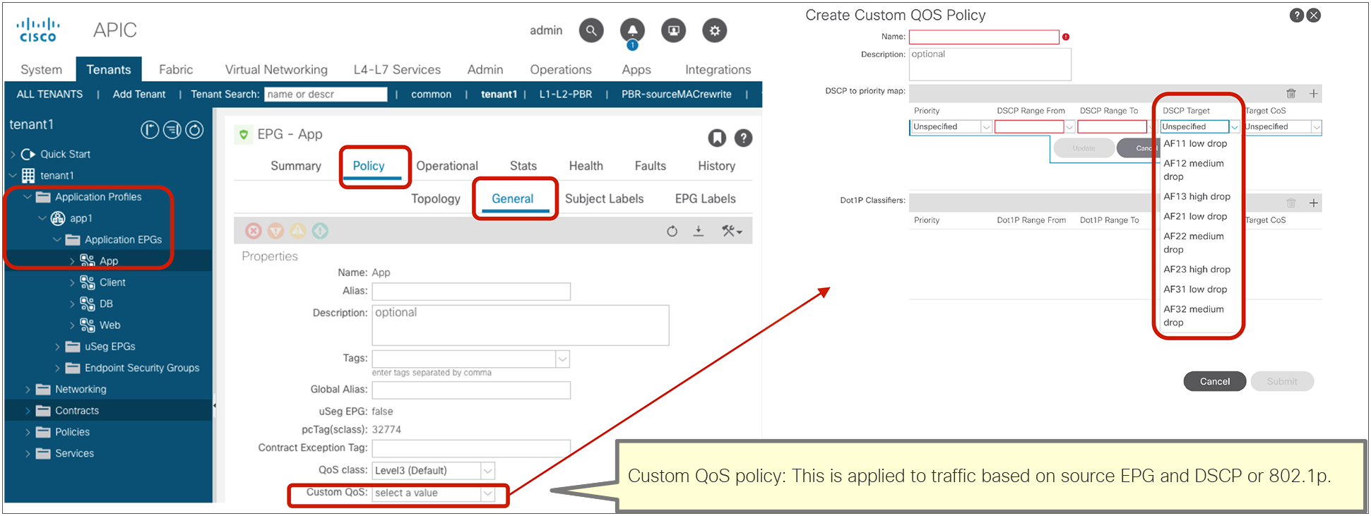
Custom QoS policy configuration at EPG
DSCP configurations for L3Out are at L3Out EPG and L3Out logical interface profile.
● Custom QoS policy configuration for L3Out logical interface is at Tenant > Networking > L3Outs > L3Out_name > Logical Node Profiles > Logical_Node_Profile_name > Logical Interface Profiles > Logical_Interface_Profile_name > Policy > General.
● Target DSCP configuration location for L3Out EPG is at Tenant > Networking > L3Outs > L3Out_name > External EPGs > External_EPG_name > Policy > General.
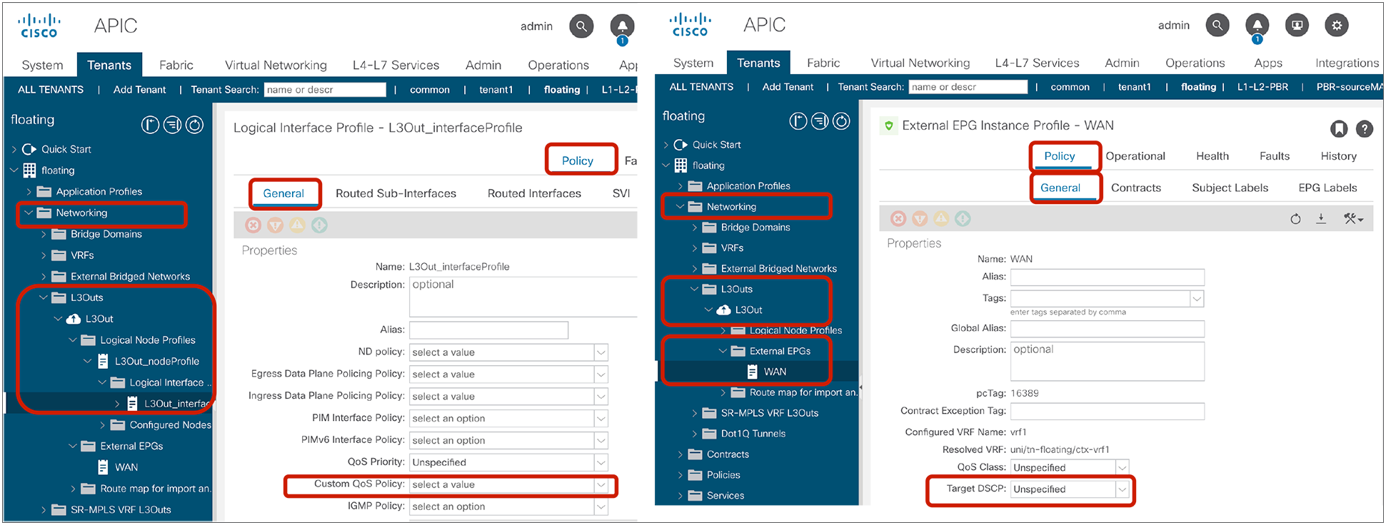
Custom QoS policy and Target DSCP configuration for L3Out
Note: After Cisco APIC Release 4.0, use of Custom QoS policy at L3Out logical interface profile is recommended for L3Out QoS.
Contract subject configurations
The contract subject configuration location is at Tenant > Contract > Contract_name > Subject_name.

Contract subject configuration
Apply Both Directions and Reverse Filter Ports
Apply Both Directions and Reverse Filter ports are better explained with an example. Consider Figure 93, below: the consumer EPG (Web EPG) needs to have access to the provider EPG (App EPG) port 22. For the communication to be possible, Cisco ACI must create a filter in the consumer-to-provider direction with destination TCP port 22 and a filter in the provider-to-consumer direction with source TCP port 22.
This is what the default configuration “Apply Both Directions and Reverse Filter Ports” does:
● The Apply Both Directions option is to apply the contract filter (in this example, it is the filter for TCP with destination port 22) on both consumer-to-provider and provider-to-consumer directions.
● The Reverse Filter Ports option is to make sure that the filter used in the provider-to-consumer direction is from port 22 (that is, the filter of the consumer-to-provider direction reversed). This option is available only if Apply Both Directions is enabled. The Reverse Filter Ports option is to reverse the source and destination ports for the provider-to-consumer direction.
Figure 93 illustrates an example in which both options are enabled. By enabling Apply Both Directions, two TCAM entries for consumer-to-provider and provider-to-consumer directions are created. The entry for the consumer-to-provider direction uses the source and destination ports that have been defined in the filter. The entry for the provider-to-consumer direction uses as a source port the port defined in the filter as the destination port, and as a destination port the port defined in the filter as the source port – in other words, the filter’s ports are reversed. Thus, bidirectional traffic between consumer EPG and provider EPG is permitted.
Example where Apply Both Directions is enabled and Reverse Filter Ports is enabled
Figure 94 provides an example in which Apply Both Directions is enabled, but Reverse Filter Ports is disabled. As you can see, this configuration is not useful because the provider would generate traffic from port 22 and not to port 22. This configuration is not common though the configuration itself is possible.

Example where Apply Both Directions is enabled and Reverse Filter Ports is disabled
Figure 95 shows the GUI configuration called “Create Contract Subject” on APIC if Apply Both Directions is disabled. This allows us to use different filters for each direction.

Create Contract Subject GUI (Apply Both Directions is disabled.)
Figure 96 illustrates the fact that you can disable Apply Both Directions when you want to configure filters for each direction separately. This option can be useful if you want to permit specific L4 ports for one direction only, as when you have a streaming server in the provider EPG that is generating UDP traffic from a specific set of ports.

Example where Apply Both Directions is disabled, with independent configuration of filters for the consumer-to-provider direction and the provider-to-consumer direction
L4-L7 Service Graph and Policy Based Redirect (PBR)
This is the option to insert L4-L7 service devices such as firewall, load balancer, and IPS between the consumer and provider EPGs by using a service graph. By attaching a service graph to a contract subject, Cisco ACI creates internal EPGs (also known as “service EPGs” or “shadow EPGs”) for the service device interfaces or vNICs, and zoning rules are updated accordingly. This option also provides the ability to perform the redirect action (PBR: Policy Based Redirect) and to copy action instead of permit action. Service Graph with PBR and copy was introduced in Cisco APIC Release 2.0.
This document focuses on how zoning rules are changed because of service graph. It doesn’t cover service graph design considerations or how to configure service graph. For more information on service graph and PBR, please refer to the white papers below:
● Service Graph Design with Cisco Application Centric Infrastructure White Paper: https://www.cisco.com/c/en/us/solutions/collateral/data-center-virtualization/application-centric-infrastructure/white-paper-c11-734298.html.
● Cisco Application Centric Infrastructure Policy-Based Redirect Service Graph Design White Paper: https://www.cisco.com/c/en/us/solutions/data-center-virtualization/application-centric-infrastructure/white-paper-c11-739971.html.
Service graph with permit action
“Service graph with permit action” refers to the use of service graph to allow the traffic between EPGs to flow through an L4-L7 device. This is typically used when the service device has interfaces for client-side/server-side or outside/inside that are in the same BD as consumer/provider endpoints, respectively.
Figure 97 and the CLI output from the “show zoning-rule” command, below the figure, illustrate an example. Once the service graph is deployed, the internal EPGs for the service node are created and zoning rules are updated to permit traffic between the consumer and the provider EPGs through the service node.
Insert a firewall service graph with permit action
Pod1-Leaf1# show zoning-rule scope 2850817
+---------+--------+--------+----------+----------------+---------+---------+------+----------+----------------------+
| Rule ID | SrcEPG | DstEPG | FilterID | Dir | operSt | Scope | Name | Action | Priority |
+---------+--------+--------+----------+----------------+---------+---------+------+----------+----------------------+
| 4208 | 0 | 0 | implicit | uni-dir | enabled | 2850817 | | deny,log | any_any_any(21) |
| 4244 | 0 | 0 | implarp | uni-dir | enabled | 2850817 | | permit | any_any_filter(17) |
| 4211 | 0 | 15 | implicit | uni-dir | enabled | 2850817 | | deny,log | any_vrf_any_deny(22) |
| 4222 | 0 | 16386 | implicit | uni-dir | enabled | 2850817 | | permit | any_dest_any(16) |
| 4246 | 32775 | 16388 | 69 | bi-dir | enabled | 2850817 | | permit | fully_qual(7) |
| 4247 | 16388 | 32775 | 71 | uni-dir-ignore | enabled | 2850817 | | permit | fully_qual(7) |
| 4250 | 0 | 32773 | implicit | uni-dir | enabled | 2850817 | | permit | any_dest_any(16) |
| 4253 | 32774 | 32779 | default | uni-dir-ignore | enabled | 2850817 | | permit | src_dst_any(9) |
| 4219 | 32779 | 32774 | default | bi-dir | enabled | 2850817 | | permit | src_dst_any(9) |
+---------+--------+--------+----------+----------------+---------+---------+------+----------+----------------------+
The red-highlighted lines are created because of the service graph. Instead of having two entries to permit traffic between consumer and provider EPG class IDs (as it happens with a contract without service graph), four entries are created. Two rules are defined between the consumer EPG and the consumer side of the service node (Rule IDs 4246 and 4247):
● Traffic from Web EPG (32775) to the consumer side of the service node (16388) is permitted.
● Traffic from the consumer side of the service node (16388) to Web EPG (32775) is permitted.
The other two rules are for the provider EPG and the provider side of the service node (Rule IDs 32774 and 32779):
● Traffic from App EPG (32774) to the provider side of the service node (32779) is permitted.
● Traffic from the provider side of the service node (32779) to App EPG (32774) is permitted.
The zoning rule that includes the consumer EPG class ID uses the filter defined based on the filter used in the contract subject (Rule IDs 4246 and 4247). However, the zoning rule that does not include the consumer EPG class ID uses the default filter that permits all (“Unspecified”) by default (Rule IDs 32774 and 32779). This is to reduce TCAM consumption for the entries after the first service node. After Cisco APIC Release 4.2(3), the Filters-from-contract option allows you to use the filter based on the filter used in the contract subject instead of the default filter. The configuration location is at Tenant > Services > L4-L7 > Service Graph Templates > Service_Graph_Template_name > Policy > Connections. It is “allow-all” by default.
Figure 98 and the CLI output from the “show zoning-rule” command, below the figure, illustrate an example with Filters-from-contract enabled.
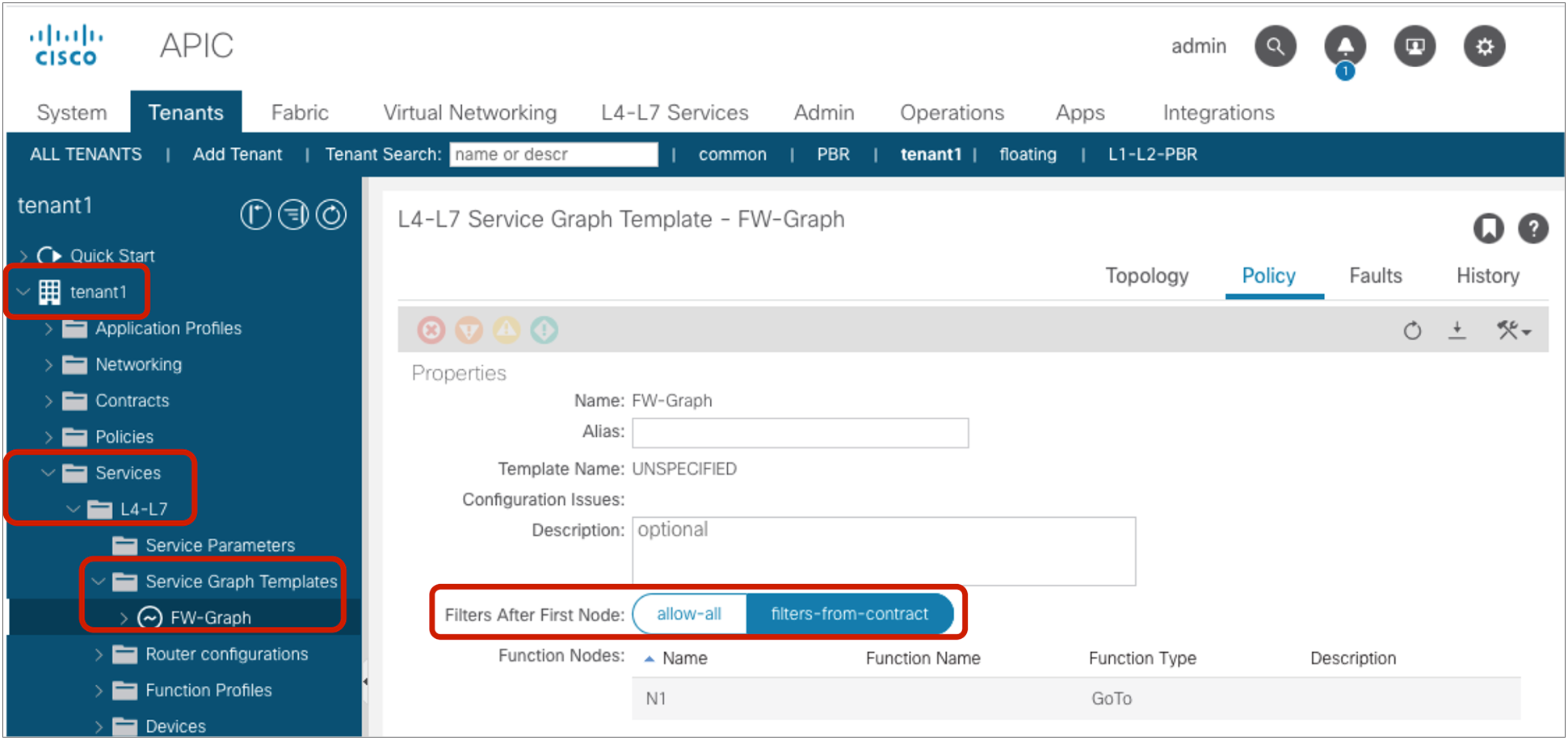
Filters After First Node
Pod1-Leaf1# show zoning-rule scope 2850817
+---------+--------+--------+----------+----------------+---------+---------+------+----------+----------------------+
| Rule ID | SrcEPG | DstEPG | FilterID | Dir | operSt | Scope | Name | Action | Priority |
+---------+--------+--------+----------+----------------+---------+---------+------+----------+----------------------+
| 4208 | 0 | 0 | implicit | uni-dir | enabled | 2850817 | | deny,log | any_any_any(21) |
| 4244 | 0 | 0 | implarp | uni-dir | enabled | 2850817 | | permit | any_any_filter(17) |
| 4211 | 0 | 15 | implicit | uni-dir | enabled | 2850817 | | deny,log | any_vrf_any_deny(22) |
| 4222 | 0 | 16386 | implicit | uni-dir | enabled | 2850817 | | permit | any_dest_any(16) |
| 4246 | 32775 | 16388 | 69 | bi-dir | enabled | 2850817 | | permit | fully_qual(7) |
| 4247 | 16388 | 32775 | 71 | uni-dir-ignore | enabled | 2850817 | | permit | fully_qual(7) |
| 4228 | 0 | 32773 | implicit | uni-dir | enabled | 2850817 | | permit | any_dest_any(16) |
| 4210 | 32779 | 32774 | 69 | bi-dir | enabled | 2850817 | | permit | fully_qual(7) |
| 4206 | 32774 | 32779 | 71 | uni-dir-ignore | enabled | 2850817 | | permit | fully_qual(7) |
+---------+--------+--------+----------+----------------+---------+---------+------+----------+----------------------+
Internal EPGs for the service node do not show up under Application Profile, unlike EPGs created by the user. Class IDs for the internal EPGs for the service node can be found at Tenant > Services > L4-L7 > Deployed Graph Instances > Deployed_Graph_Instance_name > Function_Node > Policy.
Class IDs for the internal EPGs for the service node
Once the service graph template is removed from the contract subject, internal EPGs for the service node get deleted, and the zoning rule gets changed back to the two entries that permit traffic between the consumer and provider EPGs. The CLI output from the “show zoning-rule” command below shows an example.
Pod1-Leaf1# show zoning-rule scope 2850817
+---------+--------+--------+----------+----------------+---------+---------+-------------------+----------+----------------------+
| Rule ID | SrcEPG | DstEPG | FilterID | Dir | operSt | Scope | Name | Action | Priority |
+---------+--------+--------+----------+----------------+---------+---------+-------------------+----------+----------------------+
| 4208 | 0 | 0 | implicit | uni-dir | enabled | 2850817 | | deny,log | any_any_any(21) |
| 4244 | 0 | 0 | implarp | uni-dir | enabled | 2850817 | | permit | any_any_filter(17) |
| 4211 | 0 | 15 | implicit | uni-dir | enabled | 2850817 | | deny,log | any_vrf_any_deny(22) |
| 4222 | 0 | 16386 | implicit | uni-dir | enabled | 2850817 | | permit | any_dest_any(16) |
| 4228 | 0 | 32773 | implicit | uni-dir | enabled | 2850817 | | permit | any_dest_any(16) |
| 4229 | 32775 | 32774 | 69 | bi-dir | enabled | 2850817 | tenant1:Contract1 | permit | fully_qual(7) |
| 4225 | 32774 | 32775 | 71 | uni-dir-ignore | enabled | 2850817 | tenant1:Contract1 | permit | fully_qual(7) |
+---------+--------+--------+----------+----------------+---------+---------+-------------------+----------+----------------------+
Service graph with redirect action (bidirectional PBR)
This subsection covers how Cisco ACI programs the policy-cam when using a service graph to redirect traffic to an L4-L7 device for both consumer-to-provider and provider-to-consumer directions. This is typically used for firewall or IPS insertion where the firewall or IPS does not change the source or destination IP (meaning that the firewall or IPS does not perform Network Address Translation (NAT) on the traffic). The service device can be in the same or a different bridge domain from the consumer/provider endpoints.
Figure 100 and the CLI output from the “show zoning-rule” command, below the figure, illustrate an example with redirect action. Once the service graph is deployed, internal EPGs for the service node are created and zoning rules are updated to permit traffic between the consumer and the provider EPGs through the service node. (This example doesn’t use the Filters-from-contract option).
Insert a firewall service graph with redirect action
Pod1-Leaf1# show zoning-rule scope 2850817
+---------+--------+--------+----------+----------------+---------+---------+------+------------------+----------------------+
| Rule ID | SrcEPG | DstEPG | FilterID | Dir | operSt | Scope | Name | Action | Priority |
+---------+--------+--------+----------+----------------+---------+---------+------+------------------+----------------------+
| 4208 | 0 | 0 | implicit | uni-dir | enabled | 2850817 | | deny,log | any_any_any(21) |
| 4244 | 0 | 0 | implarp | uni-dir | enabled | 2850817 | | permit | any_any_filter(17) |
| 4211 | 0 | 15 | implicit | uni-dir | enabled | 2850817 | | deny,log | any_vrf_any_deny(22) |
| 4222 | 0 | 16386 | implicit | uni-dir | enabled | 2850817 | | permit | any_dest_any(16) |
| 4229 | 16388 | 32775 | 71 | uni-dir | enabled | 2850817 | | permit | fully_qual(7) |
| 4225 | 32774 | 32775 | 71 | uni-dir-ignore | enabled | 2850817 | | redir(destgrp-4) | fully_qual(7) |
| 4248 | 32775 | 32774 | 69 | bi-dir | enabled | 2850817 | | redir(destgrp-5) | fully_qual(7) |
| 4228 | 0 | 32773 | implicit | uni-dir | enabled | 2850817 | | permit | any_dest_any(16) |
| 4254 | 32779 | 32774 | default | uni-dir | enabled | 2850817 | | permit | src_dst_any(9) |
+---------+--------+--------+----------+----------------+---------+---------+------+------------------+----------------------+
The red-highlighted lines are created because of the service graph. Instead of having two entries to permit traffic between consumer and provider EPG class IDs, four entries are created. Two are for redirect actions between the consumer and provider EPGs (Rule IDs 4225 and 4248):
● The traffic from Web EPG (32775) to App EPG (32774) is redirected to “destgrp-4” (the consumer side of the service node).
● The traffic from App EPG (32774) to Web EPG (32775) is redirected to “destgrp-5” (the provider side of the service node).
The other two are to permit traffic coming back to the fabric from the service node after the redirection (Rule IDs 4229 and 4254):
● The traffic from the provider side of the service node (16388) to Web EPG is permitted.
● The traffic from the provider side of the service node (32779) to App EPG is permitted.
Service graph with redirect action (unidirectional PBR)
This subsection covers a service graph with redirect action for either a consumer-to-provider or a provider-to-consumer direction. This is typically used for a load balancer or NAT device insertion that does not require PBR for both directions because the other direction is destined to a VIP (Virtual IP address) or an NAT address on the device. The service device can be in the same or a different bridge domain from the consumer/provider endpoint.
Figure 101 and the CLI output from the “show zoning-rule” command, below the figure, illustrate an example using redirect action. Once the service graph is deployed, internal EPGs for the service node are created and zoning rules are updated to permit traffic between the consumer and the provider EPGs through the service node. (This example doesn’t use the Filters-from-contract option).

Insert a load balancer service graph with redirect action (unidirectional PBR)
Pod1-Leaf1# show zoning-rule scope 2850817
+---------+--------+--------+----------+----------------+---------+---------+------+------------------+----------------------+
| Rule ID | SrcEPG | DstEPG | FilterID | Dir | operSt | Scope | Name | Action | Priority |
+---------+--------+--------+----------+----------------+---------+---------+------+------------------+----------------------+
| 4208 | 0 | 0 | implicit | uni-dir | enabled | 2850817 | | deny,log | any_any_any(21) |
| 4244 | 0 | 0 | implarp | uni-dir | enabled | 2850817 | | permit | any_any_filter(17) |
| 4211 | 0 | 15 | implicit | uni-dir | enabled | 2850817 | | deny,log | any_vrf_any_deny(22) |
| 4222 | 0 | 16386 | implicit | uni-dir | enabled | 2850817 | | permit | any_dest_any(16) |
| 4254 | 32775 | 16389 | 8 | bi-dir | enabled | 2850817 | | permit | fully_qual(7) |
| 4228 | 0 | 32773 | implicit | uni-dir | enabled | 2850817 | | permit | any_dest_any(16) |
| 4248 | 32774 | 32775 | 9 | uni-dir | enabled | 2850817 | | redir(destgrp-6) | fully_qual(7) |
| 4225 | 16389 | 32775 | 9 | uni-dir-ignore | enabled | 2850817 | | permit | fully_qual(7) |
| 4229 | 49157 | 32774 | default | uni-dir | enabled | 2850817 | | permit | src_dst_any(9) |
+---------+--------+--------+----------+----------------+---------+---------+------+------------------+----------------------+
The red-highlighted lines are created because of the service graph. Instead of having two entries to permit traffic between the consumer and provider EPG class IDs (as would be the case for a contract without a service graph), four entries are created. Two rules are for between the consumer EPG and the consumer side of the service node (Rule IDs 4254 and 4225):
● The traffic from Web EPG (32775) to the consumer side of the service node (16389) is permitted.
● The traffic from the consumer side of the service node (16389) to Web EPG (32775) is permitted.
The other two rules are to permit traffic coming back to the fabric from the provider side of the service node and a redirect action for return traffic from the provider to the consumer. (Rule IDs 4248 and 4229):
● The traffic from the provider side of the service node (49157) to App EPG (32774) is permitted.
● The traffic from App EPG (32774) to Web EPG (32775) is redirected to “destgrp-6” (the provider side of the service node).
As you can see, the permit entry for the traffic from the provider EPG (32774) to the provider side of the service node (49157) is not created, by default. This entry can be useful when there is traffic destined to, or generated by, the service device itself. As an example, for the keepalive traffic from the load balancer to the real servers in the provider EPG, the “Direct Connect” option must be set to “True.” This option creates a rule to permit traffic from the EPG where the endpoints are, and from the service EPG where the service interface is connected. The configuration location is at Tenant > Services > L4-L7 > Service Graph Templates > Service_Graph_Template_name > Policy > Connections. It is set to “False” by default.

Direct Connect options
The CLI output from “show zoning-rule” command, below, shows an example with the “Direct Connect” option set to “True” on the connector between the provider side of the service node and the provider EPG, which has a permit entry for the traffic from the provider EPG (32774) to the provider side of the service node (49157).
Pod1-Leaf1# show zoning-rule scope 2850817
+---------+--------+--------+----------+----------------+---------+---------+------+------------------+----------------------+
| Rule ID | SrcEPG | DstEPG | FilterID | Dir | operSt | Scope | Name | Action | Priority |
+---------+--------+--------+----------+----------------+---------+---------+------+------------------+----------------------+
| 4208 | 0 | 0 | implicit | uni-dir | enabled | 2850817 | | deny,log | any_any_any(21) |
| 4244 | 0 | 0 | implarp | uni-dir | enabled | 2850817 | | permit | any_any_filter(17) |
| 4211 | 0 | 15 | implicit | uni-dir | enabled | 2850817 | | deny,log | any_vrf_any_deny(22) |
| 4222 | 0 | 16386 | implicit | uni-dir | enabled | 2850817 | | permit | any_dest_any(16) |
| 4254 | 32775 | 16389 | 8 | bi-dir | enabled | 2850817 | | permit | fully_qual(7) |
| 4228 | 0 | 32773 | implicit | uni-dir | enabled | 2850817 | | permit | any_dest_any(16) |
| 4248 | 32774 | 32775 | 9 | uni-dir | enabled | 2850817 | | redir(destgrp-6) | fully_qual(7) |
| 4225 | 16389 | 32775 | 9 | uni-dir-ignore | enabled | 2850817 | | permit | fully_qual(7) |
| 4229 | 49157 | 32774 | default | bi-dir | enabled | 2850817 | | permit | src_dst_any(9) |
| 4253 | 32774 | 49157 | default | uni-dir-ignore | enabled | 2850817 | | permit | src_dst_any(9) |
+---------+--------+--------+----------+----------------+---------+---------+------+------------------+----------------------+
Service graph with copy action
This subsection covers a service graph with copy action for both consumer-to-provider and provider-to-consumer directions. This is useful to selectively monitor traffic or when an IDS (Intrusion Detection System) is included in your network. The service device interface will be in a copy BD that is automatically created per VRF through service-graph deployment. Copy BDs are in the copy VRF that is automatically created in a common tenant.
Figure 103 and the CLI output from the “show zoning-rule” command, below the figure, illustrate an example of a service graph with copy action. Once a service graph is deployed, zoning rules are updated to send a copy of traffic between the consumer and the provider EPGs to the service node.

Insert a firewall service graph with copy action
Pod1-Leaf1# show zoning-rule scope 2850817
+---------+--------+--------+----------+----------------+---------+---------+------+------------------------+----------------------+
| Rule ID | SrcEPG | DstEPG | FilterID | Dir | operSt | Scope | Name | Action | Priority |
+---------+--------+--------+----------+----------------+---------+---------+------+------------------------+----------------------+
| 4209 | 0 | 0 | implicit | uni-dir | enabled | 2850817 | | deny,log | any_any_any(21) |
| 4229 | 0 | 0 | implarp | uni-dir | enabled | 2850817 | | permit | any_any_filter(17) |
| 4207 | 0 | 15 | implicit | uni-dir | enabled | 2850817 | | deny,log | any_vrf_any_deny(22) |
| 4212 | 0 | 16386 | implicit | uni-dir | enabled | 2850817 | | permit | any_dest_any(16) |
| 4265 | 0 | 32774 | implicit | uni-dir | enabled | 2850817 | | permit | any_dest_any(16) |
| 4270 | 16387 | 16388 | 69 | bi-dir | enabled | 2850817 | | copy(destgrp-5),permit | fully_qual(7) |
| 4253 | 16388 | 16387 | 71 | uni-dir-ignore | enabled | 2850817 | | copy(destgrp-5),permit | fully_qual(7) |
+---------+--------+--------+----------+----------------+---------+---------+------+------------------------+----------------------+
The red-highlighted lines are updated because of the service graph with copy action. In addition to permit action, copy action is added to the two entries for traffic between the consumer and provider EPG class IDs (Rule IDs 4270 and 4253):
● The traffic from Web EPG (16387) to App EPG (16388) is copied to “destgrp-5” (the copy service interface).
● The traffic from App EPG (16388) to Web EPG (16387) is copied to “destgrp-5” (the copy service interface).
This is an option to specify the class of service of the traffic matched with the contract subject. The default configuration is “Unspecified.” Cisco ACI supports six user-configurable classes. Level 4, 5, and 6 are available with Cisco Nexus 9000 EX/FX leaf and spine nodes or later after Cisco APIC Release 4.0. Please see the “QoS Class” section of this document for the precedence of each QoS configuration and supported classes.
This is an option to rewrite the DSCP (Differentiated Services Code Point) priority to the traffic matched with the contract subject. The default configuration is “Unspecified.” To use this option, the QoS Priority in the contract subject or QoS Class in the contract must be set. Please see “Target DSCP” in the section “Per-contract configuration” for the precedence of the Target DSCP configuration and supported DSCP priorities.
This is used for ACI-to-SD-WAN integration with vManage. This option is used at a contract with an L3Out connected to Cisco IOS® XE SD-WAN router (cEdge).
If APIC is added as an integration partner on vManage and policy is exchanged, WAN SLA policies are created in the common tenant on APIC. WAN SLA policy in a contract subject is to assign the WAN SLA policy created in the common tenant, so that the ACI fabric controls DSCP mapping for the traffic matched with the contract subject.

WAN SLA policy created in the common tenant
In addition to WAN SLA policy, WAN VPN is also automatically created, which needs to be mapped to a tenant VRF.

Assign WAN VPN to a VRF and WAN SLA policy to a contract
Note: To use WAN SLA policy, the QoS priority configuration must not be “Unspecified.” Target DSCP does not take effect because DSCP mapping defined in the WAN SLA policy will be used for DSCP mapping. If both are set, the WAN SLA policy will take precedence.
For the SD-WAN integration details, please refer to the following documents:
● Cisco SD-WAN configuration guide: https://www.cisco.com/c/en/us/td/docs/routers/sdwan/configuration/policies/ios-xe-16/policies-book-xe/integration-with-Cisco-ACI.html.
● Cisco ACI configuration guide: https://www.cisco.com/c/en/us/td/docs/switches/datacenter/aci/apic/sw/kb/Cisco-ACI-and-SDWAN-Integration.html.
● Cisco SD-WAN App-aware-routing: https://www.cisco.com/c/en/us/td/docs/routers/sdwan/configuration/policies/vedge/policies-book/application-aware-routing.html.
Per-filter configuration
The per-filter configuration location is at Tenant > Contract > Contract_name > Subject_name > Filter_name.

Filter configuration
This log option is to log packets and provide information about the traffic that is hitting the rule of interest. The log option also offers hit counter statistics, which are based on the amount of traffic being sent to the CPU (which, because of CoPP, is a fraction of the total traffic). The logged packets view (Tenant > Operational > Packets) shows the latest packets that hit a rule with a log option enabled. The flow view (Tenant > Operational > Flows) displays a single entry per flow, but it provides statistics about the amount traffic that is hitting policy-cam rules with the log option.
Note: Flow statistics are useful for troubleshooting in order to see which traffic is hitting the permit-and-deny entries in contracts. Please keep in mind that contract logs are rate-limited by default at 300 pps for permit and 500 pps for deny on each leaf, so the flow statistics related to permit/deny logs are not meant to be an accurate measurement of traffic of a given flow.
Note: Do not confuse the log option and the hardware statistics counters. The hardware counters are not related to the log option and are on by default for all rules (except for compressed rules). These counters are hardware-based and exact, and can be viewed by using the commands described in the section “Troubleshooting”: “show system internal policy-mgr stats” and “contract_parser.py”. These counters do not provide information about the packets that hit a rule; they let you see which rule is being hit and by how many packets. Hardware counters are not compatible with compression: compressed filters are shared by multiple contracts; as a result, they do not provide an accurate statistic for a specific filter in a specific contract.
The directive option “Log” is not checked, by default, but the implicit deny entry has the log enabled: this means that with allow list contracts, dropped traffic is logged. You can see the packets/flows logged from the APIC, or by connecting to the individual leaf nodes and using CLI commands, or by exporting them via syslog directly from the leaf nodes.
The information that Cisco ACI provides for logged packets is: VRF, source and destination MAC, source and destination IP, protocol, source and destination port, source and destination EPGs, and source interface. Packet logs also include the packet length, which is not part of the flow statistics (for obvious reasons).
Note: The EPG information as part of the logs has been introduced in Cisco APIC Release 3.2.
These are the possible configurations and their effect on logging:
● If “Log” is not checked (the default configuration), traffic that is dropped because of the implicit deny is logged.
● If a deny rule is configured by the user (the action is “Deny”) and the “Log” option is not checked, the traffic that is dropped because of this rule is not logged.
● If the action is “Deny” and “Log” is checked, logging for denied traffic is enabled.
● If the action is “Permit” and “Log” is checked, logging for permitted traffic is enabled. Permit logging requires Cisco APIC Release 2.0 or later, and EX or later.
If you are exporting the logs from the leaf nodes to a syslog server, in addition to entering the syslog server information in the monitoring policies, you also need to set the logging level by changing the policy for syslog messages from “default” to “info” at Fabric > Fabric Policies > Monitoring Policies > Common Policy > Syslog Message Policies > Policy for system syslog messages.
Figure 107 and the CLI output from the “show zoning-rule” command, below the figure, illustrate an example with permit logging.

Permit logging example
Pod1-Leaf1# show zoning-rule scope 2850817
+---------+--------+--------+----------+----------------+---------+---------+-------------------+------------+----------------------+
| Rule ID | SrcEPG | DstEPG | FilterID | Dir | operSt | Scope | Name | Action | Priority |
+---------+--------+--------+----------+----------------+---------+---------+-------------------+------------+----------------------+
| 4208 | 0 | 0 | implicit | uni-dir | enabled | 2850817 | | deny,log | any_any_any(21) |
| 4244 | 0 | 0 | implarp | uni-dir | enabled | 2850817 | | permit | any_any_filter(17) |
| 4211 | 0 | 15 | implicit | uni-dir | enabled | 2850817 | | deny,log | any_vrf_any_deny(22) |
| 4222 | 0 | 16386 | implicit | uni-dir | enabled | 2850817 | | permit | any_dest_any(16) |
| 4228 | 0 | 32773 | implicit | uni-dir | enabled | 2850817 | | permit | any_dest_any(16) |
| 4221 | 32774 | 32775 | 71 | uni-dir-ignore | enabled | 2850817 | tenant1:Contract1 | log,permit | fully_qual(7) |
| 4207 | 32775 | 32774 | 69 | bi-dir | enabled | 2850817 | tenant1:Contract1 | log,permit | fully_qual(7) |
+---------+--------+--------+----------+----------------+---------+---------+-------------------+------------+----------------------+
The red-highlighted lines (Rule IDs 4221 and 4201) have filters in the contract subject with “Log” checked and permit action. The action for the entries is “log, permit” instead of “permit”. You can also see that the implicit deny rule has a “deny, log” action because “deny logging” is enabled by default.
The log feature is implemented as part of the policy-cam filtering rule on the leaf nodes, but APIC provides a unified view of the logs without the need for the administrator to connect to each leaf individually: APIC collects the information from all the leaf nodes.
The logged information is available as:
● Packet logs
◦ Individual packets that are permitted or dropped by a policy-cam rule that has the log enabled, are logged.
◦ Packet logging is rate-limited by default at 500 pps for dropped traffic and 300 pps for traffic hitting a permit rule, but you can change the default by modifying the CoPP configuration at Fabric > Access Policies > Policies > Switch > CoPP Leaf. The ACLLOG entry sets the rate limiting for dropped traffic, and PERMIT LOG sets the rate limiting for permitted traffic.
◦ A limited number of these logs are kept, and old logs will be replaced with new ones. Permit logging is stored up to 1000 lines per leaf, and deny logging is stored up to 400 lines per leaf.
◦ You can see the logs by using the CLI command “show logging ip access-list packet {deny | permit} [detail]” directly on each leaf.
◦ You can see the logged packets from APIC at Tenant > Operational > Packets.
● Flow log
◦ The flow logs are generated by aggregating the information from packet logs and the statistics related to the hit counts. Packets belonging to the same VRF, with the same source and destination MAC, source and destination IP, protocol, and L4 ports constitute a flow entry.
◦ You can see the flow statistics by using the CLI command “show logging ip access-list cache {deny | permit} [detail]” directly on each leaf.
◦ Flow records are kept for a longer period of time compared to packet logs. APIC manages them like statistics; therefore, how long the flows are kept in APIC depends on the configuration of Fabric > Fabric Policies > Policies > Monitoring Policies > Stats Collection Policies. These are configured per leaf.
◦ APIC regularly collects flow statistics from the leaf nodes and displays the statistics based on the aggregated hits over five minutes.
◦ Logged flows can be found at Tenant > Operational > Flows.
APIC shows the aggregated view of packet and flow logs across all the leafs in the fabric. For both types of logs, APIC organizes them further into L2 Permit, L3 Permit, L2 Drop and L3 Drop, differentiating bridged traffic from routed traffic.
Figures 108 and 109, and the CLI command outputs below the figures, provide some examples. As you can see, SSH traffic generated from 192.168.1.1 in Web EPG to 192.168.2.1 in App EPG was permitted, but others were denied. In the packet logs, you would see a list of packets hitting the contract rule (not all of them due to the rate limiting that packet logging applies to avoid overwhelming the CPU):
● In the packet log, you will see packets for the same flow multiple times, as in Figure 108.
● With the ”show logging ip access-list cache” command issued on the leaf, you would see only one entry for that specific flow and the hit count within a time window of 10 seconds.
● On the APIC, if you click on a flow entry like the ones in Figure 109, APIC will display the statistics for the number of packets that have been logged in a time window of five minutes.

Packet-to-packet logging information on the GUI (Tenant > Operational > Packets)
Pod1-Leaf1# show logging ip access-list internal packet-log permit
[2020-04-23T17:06:47.053769000+00:00]: CName: tenant1:VRF1(VXLAN: 2850817), VlanType: FD_VLAN, Vlan-Id: 89, SMac: 0x005056af31d3, DMac:0x0022bdf819ff, SIP: 192.168.1.1, DIP: 192.168.2.1, SPort: 52878, DPort: 22, Src Intf: port-channel1, Proto: 6, PktLen: 66
[2020-04-23T17:06:47.049224000+00:00]: CName: tenant1:VRF1(VXLAN: 2850817), VlanType: FD_VLAN, Vlan-Id: 89, SMac: 0x005056af31d3, DMac:0x0022bdf819ff, SIP: 192.168.1.1, DIP: 192.168.2.1, SPort: 52878, DPort: 22, Src Intf: port-channel1, Proto: 6, PktLen: 66
[2020-04-23T17:06:46.316771000+00:00]: CName: tenant1:VRF1(VXLAN: 2850817), VlanType: FD_VLAN, Vlan-Id: 89, SMac: 0x005056af31d3, DMac:0x0022bdf819ff, SIP: 192.168.1.1, DIP: 192.168.2.1, SPort: 52878, DPort: 22, Src Intf: port-channel1, Proto: 6, PktLen: 66
[2020-04-23T17:06:46.273541000+00:00]: CName: tenant1:VRF1(VXLAN: 2850817), VlanType: FD_VLAN, Vlan-Id: 89, SMac: 0x005056af31d3, DMac:0x0022bdf819ff, SIP: 192.168.1.1, DIP: 192.168.2.1, SPort: 52878, DPort: 22, Src Intf: port-channel1, Proto: 6, PktLen: 110
<snip>
Pod1-Leaf1# show logging ip access-list internal packet-log deny
[2020-04-23T17:09:06.870966000+00:00]: CName: tenant1:VRF1(VXLAN: 2850817), VlanType: FD_VLAN, Vlan-Id: 89, SMac: 0x005056af31d3, DMac:0x0022bdf819ff, SIP: 192.168.1.1, DIP: 192.168.2.1, SPort: 37702, DPort: 80, Src Intf: port-channel1, Proto: 6, PktLen: 74
[2020-04-23T17:09:01.317441000+00:00]: CName: tenant1:VRF1(VXLAN: 2850817), VlanType: FD_VLAN, Vlan-Id: 102, SMac: 0x005056af3f3b, DMac:0x0022bdf819ff, SIP: 192.168.2.1, DIP: 192.168.1.1, SPort: 49220, DPort: 22, Src Intf: port-channel2, Proto: 6, PktLen: 74
[2020-04-23T17:08:34.805576000+00:00]: CName: tenant1:VRF1(VXLAN: 2850817), VlanType: FD_VLAN, Vlan-Id: 89, SMac: 0x005056af31d3, DMac:0x0022bdf819ff, SIP: 192.168.1.1, DIP: 192.168.2.1, SPort: 37702, DPort: 80, Src Intf: port-channel1, Proto: 6, PktLen: 74
[2020-04-23T17:08:29.252068000+00:00]: CName: tenant1:VRF1(VXLAN: 2850817), VlanType: FD_VLAN, Vlan-Id: 102, SMac: 0x005056af3f3b, DMac:0x0022bdf819ff, SIP: 192.168.2.1, DIP: 192.168.1.1, SPort: 49220, DPort: 22, Src Intf: port-channel2, Proto: 6, PktLen: 74
<snip>

Contract logs displayed as flows on the GUI (Tenant > Operational > Flows)
Pod1-Leaf1# show logging ip access-list cache deny
Source MAC Destination MAC Source IP Destination IP S-Port D-Port Interface Protocol VRF VRF-Encap StartTimeStamp EndTimeStamp PktLen Hits
-------------------------------------------------------------------------------------------------------------------------------------------------------------------------------------------------------
005056af31d3 0022bdf819ff 192.168.1.1 192.168.2.1 37702 80 port-channel1 (006)TCP tenant1:VRF1 2850817 Apr 23 17:08:03 2020 Apr 23 17:09:06 2020 74 7
005056af31d3 0022bdf819ff 192.168.1.1 192.168.2.1 37694 80 port-channel1 (006)TCP tenant1:VRF1 2850817 Apr 23 16:23:15 2020 Apr 23 16:23:16 2020 74 2
005056af3f3b 0022bdf819ff 192.168.2.1 192.168.1.1 49218 22 port-channel2 (006)TCP tenant1:VRF1 2850817 Apr 23 17:06:39 2020 Apr 23 17:06:40 2020 74 2
005056af3f3b 0022bdf819ff 192.168.2.1 192.168.1.1 49220 22 port-channel2 (006)TCP tenant1:VRF1 2850817 Apr 23 17:07:58 2020 Apr 23 17:09:01 2020 74 7
Pod1-Leaf1# show logging ip access-list cache permit
Source MAC Destination MAC Source IP Destination IP S-Port D-Port Interface Protocol VRF VRF-Encap StartTimeStamp EndTimeStamp PktLen Hits
-------------------------------------------------------------------------------------------------------------------------------------------------------------------------------------------------------
005056af31d3 0022bdf819ff 192.168.1.1 192.168.2.1 52878 22 port-channel1 (006)TCP tenant1:VRF1 2850817 Apr 23 17:06:46 2020 Apr 23 17:06:47 2020 66 9
005056af3f3b 0022bdf819ff 192.168.2.1 192.168.1.1 22 52874 port-channel2 (006)TCP tenant1:VRF1 2850817 Apr 23 16:34:48 2020 Apr 23 16:34:54 2020 66 27
The following restrictions to packet and flow logging apply:
● Permit packet logging is rate-limited (300 pps), and deny packet logging is rate-limited (500 pps), but they are user-configurable via CoPP policies.
● Using the “Log” option on filters in management contracts is not supported. Using the “Log” option will cause zoning-rule deployment failure.
● The enhancement that includes the EPG information in the logs requires Cisco APIC Release 3.2 or later.
● If the contract is among uSeg EPGs or EPGs used in a shared service (including a shared L3Out), APIC does not provide the EPG fields in the logs.
● If the “Log” option is enabled on a filter chain used in a contract with a service graph PBR, the redirected traffic is logged as “L3 Permit.”
This option is to compress hardware TCAM entries to utilize less TCAM resource. Policy Compression is disabled by default. This option was introduced to compress bidirectional rules to one entry (bidirectional rule compression) in Cisco APIC Release 3.2; it was originally called “no stats.” Starting from Cisco APIC Release 4.0, it is called “Enable Policy Compression” and feature includes the capability to reuse filters (policy table compression) across multiple EPG pairs.
Table 7 summarizes the supported leaf models and features.
Table 7. Supported leaf models and features
| Cisco Nexus 9000 switch |
Cisco APIC Release 3.2 |
Cisco APIC Release 4.0 and later |
| EX Cisco Nexus 93180YC-EX Cisco Nexus 93108TC-EX Cisco Nexus 93180LC-EX |
Bidirectional rule compression |
Bidirectional rule compression |
| FX and later* Cisco Nexus 93180YC-FX Cisco Nexus 93108TC-FX Cisco Nexus 9336C-FX2 Cisco Nexus 93240YC-FX2 Cisco Nexus 9348GC-FXP Cisco Nexus 9316D-GX Cisco Nexus 93600CD-GX Cisco Nexus 9364C-GX Cisco Nexus 9332D-GX2B Cisco Nexus 93180YC-FX3 |
Bidirectional rule compression |
Bidirectional rule compression Policy table compression |
Note: Even if bidirectional rule compression and policy table compression can work at the same time by using the same configuration knob “Enable Policy Compression,” each compression works separately. If bidirectional rule compression is not applicable because “Apply Both Directions and Reverse Filter Ports” are not enabled, Cisco ACI performs only policy table compression. If policy table compression fails for some reason (such as hash collision), ACI applies only bidirectional rule compression.
The capability to compress bidirectional rules to one entry (bidirectional rule compression) requires Cisco APIC Release 3.2 or later and EX leaf or later. This capability requires that both Apply Both Directions and Reverse Filter Ports are enabled in the contract, which is the default configuration. If both are enabled, one contract creates two entries for both directions (consumer-to-provider and provider-to-consumer) of the traffic, as shown in Figure 110. If “Enable Policy Compression” is checked, bidirectional entries will take one entry only in the TCAM, instead of two.

Contracts are bidirectional by default and consume two entries in the TCAM
This capability to reuse filters (policy table compression) requires Cisco APIC Release 4.0 or later and FX leaf nodes or later. By default, even if multiple pairs of EPGs use the same contract with the same filter, separate entries are allocated in the TCAM for every pair of EPGs, as shown in Figure 111.

By default, even if the same contract is reused by multiple EPGs, the same filter is programmed multiple times in the TCAM, once per EPG pair
If you select the option “Enable Policy Compression,” Cisco ACI programs an indirect association between EPG pairs and filters by using a label called policy group (PG). The EPG pairs are programmed in the PG table with a label that points to the filters. Both the policy group table and the filters are programmed in the TCAM, but the usage of the TCAM space is more efficient with the indirection in case the same contract (and, as a result, the filter) is reused multiple times. Figure 112 illustrates this point.

Reuse filters (Enable Policy Compression)
How many TCAM entries “Enable Policy Compression” can reduce depends on the contract design, such as how many EPG pairs can be combined to one policy group label. Please also see the section “Scalability considerations.”
Figure 113 and the CLI output from the “show zoning-rule” command, below the figure, clarify how compression works.

Enable Policy Compression example
Pod1-Leaf1# show zoning-rule scope 2850817
+---------+--------+--------+----------+----------------+---------+---------+-------------------+-----------------+----------------------+
| Rule ID | SrcEPG | DstEPG | FilterID | Dir | operSt | Scope | Name | Action | Priority |
+---------+--------+--------+----------+----------------+---------+---------+-------------------+-----------------+----------------------+
| 4207 | 32774 | 32775 | 71 | uni-dir-ignore | enabled | 2850817 | tenant1:Contract1 | no_stats,permit | fully_qual(7) |
| 4211 | 0 | 16386 | implicit | uni-dir | enabled | 2850817 | | permit | any_dest_any(16) |
| 4244 | 32775 | 32774 | 69 | bi-dir | enabled | 2850817 | tenant1:Contract1 | no_stats,permit | fully_qual(7) |
| 4208 | 0 | 0 | implicit | uni-dir | enabled | 2850817 | | deny,log | any_any_any(21) |
| 4222 | 0 | 0 | implarp | uni-dir | enabled | 2850817 | | permit | any_any_filter(17) |
| 4221 | 0 | 15 | implicit | uni-dir | enabled | 2850817 | | deny,log | any_vrf_any_deny(22) |
| 4254 | 0 | 32773 | implicit | uni-dir | enabled | 2850817 | | permit | any_dest_any(16) |
+---------+--------+--------+----------+----------------+---------+---------+-------------------+-----------------+----------------------+
The “Action” in the CLI command output for the red-highlighted lines is “no_stats, permit,” instead of “permit,” because of the enabling of “Enable Policy Compression”. The bi-dir and uni-dir-ignore rules are combined into one hardware entry if policy compression is enabled.
Here is a list of a few considerations related to Policy Compression:
● EX leaf nodes or newer are required to compress bidirectional rules to one entry (bidirectional rule compression).
● FX leaf nodes or newer are required to reuse filters (policy table compression).
● Policy Compression is applied for the rules that are present in re-used contracts. ACI is not going to compare the filters across different contracts in order to figure out whether it is possible to reuse them. Prior to APIC Release 5.0, if a contract is re-used across VRFs, the optimization works in each VRF independently. Starting from APIC Release 5.0, the optimization is applied across VRFs if the same contract is reused.
● Policy Compression disables individual filter rule statistics; therefore, the hardware counters that you would be able to see when using the commands “contract_parser.py” or “show system internal policy-mgr stats” are not available with policy compression.
● Prior to APIC Release 6.1(4), Policy Compression can be enabled for permit and permit-log rules only. (No compression for rules with deny, deny-log, redirect, or copy rule). Starting from APIC Release 6.1(4), policy table compression is applicable to redirect rule as well.
● As of this writing, if “Apply Both Directions” is disabled at the contract subject, which can use separate filter rules for consumer-to-provider and provider-to-consumer directions, Policy compression takes effect on the rules for either one of the directions, not for both directions
● Policy Compression can be enabled for user-defined rules only. It is not applicable to implicit rules.
● Policy Compression doesn’t take effect on contracts that have labels and subject exceptions associated with them.
● Policy compression is implicitly enabled on the switches with High Policy profile except EX switches. This implies that contracts that have labels or subject exception don’t get the benefit of Policy compressions in the ACI fabric that contains the switches with High Policy profile except EX switches
“Deny action” was introduced in Cisco APIC Release 3.2. If a contract is defined between EPGs, protocols in filters defined in the contract are permitted because the default action is “Permit.” For each filter in a contract subject, the administrator can set the action to “Deny” instead of “Permit.” Using deny action is helpful if you want to use a block-list model for security enforcement. For example, you could configure a vzAny-to-vzAny permit contract to permit all EPG-to-EPG communication within a VRF, and then you can configure a contract with a deny action to deny specific EPG-to-EPG communication. Using deny action can simplify the configuration and reduce TCAM consumption.

Example of using deny action

Deny action configuration
A deny action has the following priority-configuration options (please refer to the deny-action priorities in the section “Contract priorities” for more details):
● Default level
● Lowest priority
● Medium priority
● Highest priority
Figure 116 and the CLI output from the “show zoning-rule” command, below the figure, illustrate an example of a policy programmed on a leaf with a deny action.

Deny action configuration example with vzAny
Pod1-Leaf1# show zoning-rule scope 2850817
+---------+--------+--------+----------+----------------+---------+---------+-------------------+----------+----------------------+
| Rule ID | SrcEPG | DstEPG | FilterID | Dir | operSt | Scope | Name | Action | Priority |
+---------+--------+--------+----------+----------------+---------+---------+-------------------+----------+----------------------+
| 4250 | 0 | 0 | implicit | uni-dir | enabled | 2850817 | | deny,log | any_any_any(21) |
| 4246 | 0 | 0 | implarp | uni-dir | enabled | 2850817 | | permit | any_any_filter(17) |
| 4208 | 0 | 15 | implicit | uni-dir | enabled | 2850817 | | deny,log | any_vrf_any_deny(22) |
| 4247 | 0 | 32777 | implicit | uni-dir | enabled | 2850817 | | permit | any_dest_any(16) |
| 4207 | 0 | 0 | 67 | uni-dir-ignore | enabled | 2850817 | tenant1:Contract1 | permit | any_any_filter(17) |
| 4253 | 0 | 0 | 68 | bi-dir | enabled | 2850817 | tenant1:Contract1 | permit | any_any_filter(17) |
| 4249 | 32774 | 32775 | 68 | uni-dir-ignore | enabled | 2850817 | tenant1:Contract2 | deny | fully_qual(7) |
| 4211 | 32775 | 32774 | 67 | bi-dir | enabled | 2850817 | tenant1:Contract2 | deny | fully_qual(7) |
+---------+--------+--------+----------+----------------+---------+---------+-------------------+----------+----------------------+
The red-highlighted lines (Rule IDs 4249 and 4211) are created because of a contract with a deny action between Web EPG and App EPG. Endpoints in the VRF1 can use SSH to communicate with each other to each other except endpoints in Web EPG to endpoints in App EPG.
Even if this example uses a vzAny-to-vzAny contract to permit traffic in the VRF along with a contract with deny action to deny specific traffic, the preferred group can be used to permit traffic along with a deny contract because the preferred group priority is even lower (priority 21).
The following list includes some key design considerations for using deny action:
● A deny action has a priority configuration option. Before using a deny action, please be familiar with the deny priorities. If you do not understand which rule wins, it is possible that adding deny entries may cause filtering results different from what you expect. You can find the information about deny priorities in the “Contract priorities” section of this document.
● A deny action configuration is per filter in the contract subject. Thus, the same filter configuration can be used with different actions in different contract subjects.
Filter entry configuration option
This section explains the following filter entry configuration options.
● Match Only Fragments
● Match DSCP
● TCP Flags
● Stateful
● Port Zero Entry
Each filter can contain one or more filter entries, which is located at Tenant > Contract > Filters > Filter_name, and the configuration location of each filter entry is at Tenant > Contract > Filters > Filter_name > Filter_entry_name.

Contract and contract subject options (GUI)
The Match Only Fragments option is to match fragments with offset greater than 0 (all fragments except the first one).
The Match Only Fragments option is disabled by default. This means that the filter configurations by default are applied to all packets (including all fragments). Thus, by default all packets matched with the filter can be permitted, dropped, copied or redirected based on the contract action. When The Match Only Fragments option is enabled, the filter configurations are applied to all fragments except the first fragment.
Note that TCP/UDP port information can only be checked in the first fragment. The followings are couple of examples:
● If a permit contract has an IP filter with “The Match Only Fragments” disabled (default), all IP packets including all fragments will be permitted.
● If a permit contract has an IP filter with “The Match Only Fragments” enabled, only IP fragments with offset greater than 0 (all IP fragments except the first one) will be permitted. Thus, the first fragment will be dropped by the implicit deny rule unless you have another permit contract.
● If a permit contract has a specific TCP port filter (such as destination TCP port 80) with “The Match Only Fragments” disabled (default) for a permit contract, all TCP traffic matched with the specific TCP port will be permitted. The fragments except the first one will be dropped by implicit deny rule unless you have another permit contract because TCP port information is in the first fragment only.
● The use of a specific TCP/UDP port filter with “The Match Only Fragments” enabled is not a valid configuration combination because TCP/UDP port information can only be checked in the first fragment whereas “The Match Only Fragments” is to match all fragments except the first one.
Match DSCP
This option is to specify DSCP (Differentiated Services Code Point) value to match in the traffic in addition to EtherType, IP protocol, source port, and destination port. By using this option, different actions can be taken depending on which DSCP value is in the packet, even if other parameters, such as source EPG, destination EPG, and filter matching, are the same. This option is set, by default, to “Unspecified” (which in Cisco ACI is the equivalent of “Any” in classic IOS or NX-OS terminology). This requires leaf nodes with “EX” or “FX” onward.
This option is to specify the TCP flag values to match traffic in addition to EtherType, IP protocol, source port, and destination port. The available TCP flags are:
● Synchronize: SYN
● Established: ACK or RST
● Acknowledgement: ACK
● Reset: RST
● Finish: FIN
Stateful
The Stateful option is to allow TCP packets from provider to consumer only if the ACK flag is set. This option is disabled by default. It is recommended to enable the Stateful option in TCP filter entries for better security except in those cases where Enable Policy Compression is required, because Policy compression cannot be applied if the Stateful option is enabled.
Figure 118 illustrates a use case. In order to let the consumer access a specific provider TCP port, the administrator must configure a consumer-side TCP port (the source port configuration in the contract filter) as wide range, to cover non-well-known source ports. The example below has two zoning rules: one rule to permit traffic from a consumer using an any-source TCP port to a provider with destination TCP port 80, and the other rule for the opposite direction. If a provider endpoint performs a SYN attack using the source TCP port 80 to a consumer endpoint, the traffic is automatically not dropped by the ACI fabric, because the traffic from the provider using source TCP port 80 to the consumer with an any destination TCP port is permitted by the contract.

Stateful option use case (SYN attack from provider; the Stateful option is not enabled)
By enabling the Stateful option in the filter entry, SYN packets from the provider to the consumer are dropped because the ACK bit is not set in the packet.

Stateful option use case (SYN attack from provider; the Stateful option is enabled)
When normal TCP packets from the provider to the consumer are permitted:
● Data packets (after a three-way handshake): These packets have the ACK bit set, so leaf nodes permit the packets.
● RST packet: RST packets also have ACK bit set, so leaf nodes permit RST packets.
● FIN packet: FIN packets with ACK bit set are permitted. FIN packets without ACK will be dropped. The handling of FIN packets without ACK differs based on the type of the operating system; therefore, it can be used for a FIN scan attack to determine the operating system. Dropping such packets can prevent such attacks.
Figure 120 and the CLI output from the “show zoning-rule” command, below the figure, illustrate an example of a policy programmed on a leaf with the Stateful option enabled.

Policy programmed with Stateful option enabled
Pod1-Leaf1# show zoning-rule scope 2850817
+---------+--------+--------+----------+---------+---------+---------+-------------------+----------+----------------------+
| Rule ID | SrcEPG | DstEPG | FilterID | Dir | operSt | Scope | Name | Action | Priority |
+---------+--------+--------+----------+---------+---------+---------+-------------------+----------+----------------------+
| 4250 | 0 | 0 | implicit | uni-dir | enabled | 2850817 | | deny,log | any_any_any(21) |
| 4246 | 0 | 0 | implarp | uni-dir | enabled | 2850817 | | permit | any_any_filter(17) |
| 4208 | 0 | 15 | implicit | uni-dir | enabled | 2850817 | | deny,log | any_vrf_any_deny(22) |
| 4247 | 0 | 32777 | implicit | uni-dir | enabled | 2850817 | | permit | any_dest_any(16) |
| 4222 | 32774 | 32775 | 71 | uni-dir | enabled | 2850817 | tenant1:Contract1 | permit | fully_qual(7) |
| 4244 | 32775 | 32774 | 69 | uni-dir | enabled | 2850817 | tenant1:Contract1 | permit | fully_qual(7) |
+---------+--------+--------+----------+---------+---------+---------+-------------------+----------+----------------------+
The red-highlighted lines are created by Contract1 between EPG Web and EPG App. The details of the filter entry information can be checked by using the command “show zoning-filter filter FilterID.” The filter ID 71 used in the provider-to-consumer direction has TcpRules “ack.”
Pod1-Leaf1# show zoning-filter filter 69
+----------+------+--------+-------------+------+-------------+----------+-------------+-------------+-----------+---------+-------+-------------+-------------+----------+
| FilterId | Name | EtherT | ArpOpc | Prot | ApplyToFrag | Stateful | SFromPort | SToPort | DFromPort | DToPort | Prio | Icmpv4T | Icmpv6T | TcpRules |
+----------+------+--------+-------------+------+-------------+----------+-------------+-------------+-----------+---------+-------+-------------+-------------+----------+
| 69 | 69_0 | ip | unspecified | tcp | no | yes | unspecified | unspecified | 22 | 22 | dport | unspecified | unspecified | |
+----------+------+--------+-------------+------+-------------+----------+-------------+-------------+-----------+---------+-------+-------------+-------------+----------+
Pod1-Leaf1# show zoning-filter filter 71
+----------+------+--------+-------------+------+-------------+----------+-----------+---------+-------------+-------------+-------+-------------+-------------+----------+
| FilterId | Name | EtherT | ArpOpc | Prot | ApplyToFrag | Stateful | SFromPort | SToPort | DFromPort | DToPort | Prio | Icmpv4T | Icmpv6T | TcpRules |
+----------+------+--------+-------------+------+-------------+----------+-----------+---------+-------------+-------------+-------+-------------+-------------+----------+
| 71 | 71_0 | ip | unspecified | tcp | no | yes | 22 | 22 | unspecified | unspecified | flags | unspecified | unspecified | ack |
+----------+------+--------+-------------+------+-------------+----------+-----------+---------+-------------+-------------+-------+-------------+-------------+----------+
The following list summarizes some of the key design considerations related to the use of the Stateful option:
● The Stateful option is applicable to TCP traffic only.
● The Stateful option just checks the ACK flag; it does not prevent an SYN + ACK attack from the provider, unlike a stateful firewall.
● Bidirectional rule compression cannot be applied if Stateful is enabled.
Port Zero Entry
Each filter can contain one or more filter entries, which is located at Tenant > Contract > Filters > Filter_name.
Starting from APIC release 6.0(4), Port Zero Entry is introduced. The differences between a general filter entry and a Port Zero Entry are the followings:
● If port is set to “unspecified” or “0” in a general filter entry, it means the port range is “0-65535”.
● Port Zero Entry is for a filter entry with port “0”, which is mainly to deny such traffic because port “0” is defined as a reserved port by Internet Assigned Numbers Authority (IANA) and it is not supposed to be used.
Port Zero Entry has the following Direction options:
● Direction Both (default): source port “0” and destination port “0”.
● Direction Destination: source port “0” and destination port “any”(0-65535).
● Direction Source: source port “any”(0-65535) and destination port “0”.
Note: A filter entry with either the source or the destination port “0” such as a filter with the source port “0” and the destination port “80” is not supported in either general filter entry or Port Zero Entry.

Port Zero Entry
The L3Out EPG is an EPG for external endpoints that are behind external routers connected to the ACI fabric. The classification is based on matching a user-defined subnet against the source or destination IP of the traffic. The matching criteria is per VRF. As with the other EPGs under Application Profiles, the L3Out EPG belongs to a VRF, and the L3Out EPG can be part of a preferred group, and vzAny also includes the L3Out EPG.
If there are multiple L3Out EPGs in same VRF, the classification is based on longest prefix matching. Figure 122 provides an example. L3Out-EPG1 with subnet 0.0.0.0/0 is defined in L3Out1, and L3Out-EPG2 with subnet 172.16.0.0/16 is defined in L3Out2. Traffic with source IP 10.1.1.1 will be classified into L3Out-EPG1, and traffic with source IP 172.16.1.1 will be classified into L3Out-EPG2. If only L3Out-EPG1 has a contract with Web EPG, 10.1.1.1 can talk to an endpoint in Web EPG, but 172.16.1.1 cannot.

Example of L3Out EPG longest prefix match
Note: The L3Out EPG classification is based on subnet matching the user-defined “per VRF.” Cisco ACI performs the longest-prefix-match per VRF and not “per L3Out” or “per L3Out logical interface.” Thus, even if traffic with source 10.1.1.1 arrives through L3Out2, it is classified to L3Out-EPG1.
The L3Out EPG configuration location is at Tenant > Networking > L3Outs > L3Out_name > External EPGs > L3Out_EPG_name. The class ID of the L3Out EPG can be also found here. The contract for the L3Out EPG can be configured at the Contracts tab under the Policy tab.

L3Out EPG configuration options
Similar to an EPG, L3Out EPG has the following options.
● QoS Class
● Target DSCP
● Preferred group
In addition to this, QoS Priority and Custom QoS policy configurations can be done at the L3Out logical interface profile; this is the preferred option after Cisco APIC Release 4.0. Please refer to the sections ”QoS class” and “Target DSCP” in the “Contract configuration option” section for more details.
The following list includes key design considerations for the use of L3Out EPG contracts:
● The L3Out EPG is based on matching a subnet in the entire VRF. It is not per L3Out or per L3Out logical interface.
● Intra-EPG contract and intra-EPG isolation are not supported as of Cisco APIC Release 5.0.
● Custom QoS is not available at the L3Out EPG level. Thus, CoS rewrite and DSCP rewrite require Custom QoS policy per L3Out interface, which is available after the Cisco APIC Release 4.0.
● The Policy Control Enforcement Direction configuration at the VRF changes where policy is enforced for a contract between an L3Out EPG and an EPG.
● L3Out EPG with 0.0.0.0/0 subnet uses a special class ID.
● It is recommended to explicitly add the L3Out logical interface subnet to the L3Out EPG if there is traffic sourced from the L3Out logical interface subnet.
The next two subsections explain the Policy Control Enforcement Direction configuration and L3Out EPG with 0.0.0.0/0 subnet.
Policy Control Enforcement Direction (ingress or egress enforcement)
The Policy Control Enforcement Direction option was introduced in Cisco APIC Release 1.2. Its purpose is to define where policy is applied for L3Out EPG to EPG contracts. This topic was already covered in the section “Traffic flow description with policy enforcement: “ingress” and “egress” enforcement.” Please refer to that section for more details.
The configuration location is at Tenant > Networking > VRFs > VRF_name > Policy. It can be set as either “Ingress” or “Egress.”
Note: The “Egress” option is equivalent to the behavior prior to Cisco APIC Release 1.2(1). Therefore, to keep behavior consistent across upgrades, if the VRF was created prior to Release 1.2(1) and the ACI fabric is upgraded to Release 1.2(1) or later, the option is set to “Egress.” From Release 1.2(1), the default configuration is “Ingress.”

Policy Control Enforcement Direction
L3Out EPG with 0.0.0.0/0 subnet
The L3Out EPG configured with a 0.0.0.0/0 subnet uses special class IDs:
● If the L3Out EPG 0.0.0.0/0 is the destination, the destination class ID is 15.
● If the L3Out EPG 0.0.0.0/0 is the source, the source class ID is VRF class ID.
Figure 125 and the CLI output from the “show zoning-rule” command, below the figure, illustrate an example. As you can see, there is a contract between the L3Out and the Web EPG. Cisco ACI programs the policy-cam rules between the two EPGs using two different class IDs for the L3Out. The rule where the source is the Web EPG and the L3Out is the destination, uses the destination class ID of 15 for the L3Out (Rule ID 4244), and the rule where the source is the L3Out and the Web EPG is the destination, uses the source class ID of the VRF class ID (Rule ID 4206).

L3Out EPG with 0.0.0.0/0 subnet example
Pod1-Leaf1# show zoning-rule scope 2850817
+---------+--------+--------+----------+---------+---------+---------+-------------------+----------+----------------------+
| Rule ID | SrcEPG | DstEPG | FilterID | Dir | operSt | Scope | Name | Action | Priority |
+---------+--------+--------+----------+---------+---------+---------+-------------------+----------+----------------------+
| 4211 | 0 | 16386 | implicit | uni-dir | enabled | 2850817 | | permit | any_dest_any(16) |
| 4208 | 0 | 0 | implicit | uni-dir | enabled | 2850817 | | deny,log | any_any_any(21) |
| 4222 | 0 | 0 | implarp | uni-dir | enabled | 2850817 | | permit | any_any_filter(17) |
| 4221 | 0 | 15 | implicit | uni-dir | enabled | 2850817 | | deny,log | any_vrf_any_deny(22) |
| 4244 | 32775 | 15 | 71 | uni-dir | enabled | 2850817 | tenant1:Contract1 | permit | fully_qual(7) |
| 4206 | 49153 | 32775 | 69 | uni-dir | enabled | 2850817 | tenant1:Contract1 | permit | fully_qual(7) |
+---------+--------+--------+----------+---------+---------+---------+-------------------+----------+----------------------+
VRF class ID can be found at Tenant > Operational > Resource IDs > VRFs.

VRF class ID
Even if you entered 0.0.0.0/0 as a subnet in the L3Out EPG, this subnet does not also automatically match the SVI subnet of the very L3Out where you configured the L3Out EPG. Without any additional configuration, an L3Out logical interface subnet might be classified to class ID 1, depending on the topology, if the L3Out EPG matches only the 0.0.0.0/0 subnet. Class ID 1 is used for ACI-pervasive routes, such as BD subnet and L3Out logical interface subnet. The traffic from class ID 1 to any destination is permitted by an implicit permit rule. In order to avoid automatically allowing any IP that matches the SVI subnet, it is recommended to explicitly add the L3Out logical interface subnet to the L3Out EPG if there is traffic sourced from the L3Out logical interface subnet.
Figure 127 illustrates an example of unintended permit. The L3Out-EPG1 with 0.0.0.0/0 subnet and the Web EPG have a contract that creates two entries: permit 32775-to-15 and 49153-to-32775, as shown in the “show zoning-rule” output, above. L3Out1 is deployed on Leaf1 and Leaf2. The L3Out logical interface subnet range is 192.168.11.0/24. External router1 (192.168.11.1) is connected to Leaf1, and External router2 (192.168.11.2) is connected to Leaf2. An endpoint 192.168.1.1 in Web EPG is connected under Leaf1. VRF1 uses ingress enforcement mode.

Topology with an L3Out EPG configured with 0.0.0.0/0 (Topology)
In this topology, the external router’s IP is classified to class ID 1 if the IP is local to the leaf. Because of the implicit permit rule for the traffic from class ID 1 to any, traffic between 192.168.11.1 and 192.168.1.1 is permitted even without a contract.

Cisco ACI allows traffic to and from the SVI subnet if the L3Out EPG is configured with 0.0.0.0/0, if the endpoint and the IP in the L3Out SVI subnet are on the same leaf (local traffic)
If the external IP is not local to the leaf where the originating server resides, the destination IP is classified to the L3Out EPG class ID (which is 15 for an L3Out EPG of 0.0.0.0/0) instead of class ID 1. Thus, traffic from 192.168.1.1 to 192.168.11.2 is allowed by the contract on Leaf1, as shown in Figure 129. Even if Leaf2 classifies the external IP to class ID 1, the policy is not enforced on Leaf2, because the policy was already applied on Leaf1. This traffic direction is not permitted unless a permit contract is configured.

Cisco ACI does not allow traffic to the IP in the L3Out SVI subnet if the L3Out EPG is configured with 0.0.0.0/0, when the source endpoint and the destination IP are not on the same leaf (EPG to L3Out, nonlocal traffic)
However, traffic from 192.168.11.2 to 192.168.1.1 is permitted without a contract. Leaf2 classifies the external router’s IP to class ID 1 because it is local to Leaf2. Though Leaf2 does not apply policy, the source class ID information is carried to destination Leaf1, and Leaf1 permits the traffic because of the implicit rule.

Cisco ACI allows traffic from the IP in the L3Out SVI subnet to the endpoint if the L3Out EPG is configured with 0.0.0.0/0, when the destination endpoint and the source IP are not on the same leaf (L3Out to EPG, nonlocal traffic)
In order to make the filtering consistent for both directions of the traffic, and independent of whether endpoint and the L3Out SVI subnet are on the same leaf, all you need to do is add the L3Out logical interface subnet 192.168.11.0/24 to the L3Out EPG with 0.0.0.0/0.

Adding L3Out logical interface subnet to the L3Out EPG with 0.0.0.0/0
With the L3Out logical interface subnet added to the L3Out EPG, traffic between endpoints and the IP in the L3Out SVI subnet is only allowed with a contract between the Web EPG and the L3Out EPG
The red-highlighted rules below are added because of having explicitly added the 192.168.11.0/24 subnet to the L3Out-EPG1.
Pod1-Leaf1# show zoning-rule scope 2850817
+---------+--------+--------+----------+----------------+---------+---------+-------------------+----------+----------------------+
| Rule ID | SrcEPG | DstEPG | FilterID | Dir | operSt | Scope | Name | Action | Priority |
+---------+--------+--------+----------+----------------+---------+---------+-------------------+----------+----------------------+
| 4211 | 0 | 16386 | implicit | uni-dir | enabled | 2850817 | | permit | any_dest_any(16) |
| 4208 | 0 | 0 | implicit | uni-dir | enabled | 2850817 | | deny,log | any_any_any(21) |
| 4222 | 0 | 0 | implarp | uni-dir | enabled | 2850817 | | permit | any_any_filter(17) |
| 4221 | 0 | 15 | implicit | uni-dir | enabled | 2850817 | | deny,log | any_vrf_any_deny(22) |
| 4244 | 32775 | 15 | 71 | uni-dir | enabled | 2850817 | tenant1:Contract1 | permit | fully_qual(7) |
| 4206 | 49153 | 32775 | 69 | uni-dir | enabled | 2850817 | tenant1:Contract1 | permit | fully_qual(7) |
| 4216 | 32775 | 49161 | 71 | uni-dir-ignore | enabled | 2850817 | tenant1:Contract1 | permit | fully_qual(7) |
| 4243 | 49161 | 32775 | 69 | bi-dir | enabled | 2850817 | tenant1:Contract1 | permit | fully_qual(7) |
+---------+--------+--------+----------+----------------+---------+---------+-------------------+----------+----------------------+
The following lists includes some key design considerations for using L3Out EPG with 0.0.0.0/0 subnet:
● In order to avoid automatically allowing any IP that matches the SVI subnet, it is recommended to explicitly add the L3Out logical interface subnet to the L3Out EPG if there is traffic sourced from the L3Out logical interface subnet.
● It’s recommended not to use an L3Out EPG with 0.0.0.0/0 subnet as the provider along with multiple consumer EPGs in other VRFs, because it potentially allows traffic between the consumer EPGs even if there is no contract between the consumer EPGs. (The reason is explained in Appendix: Advanced use cases).
Contract priorities
This section explains contracts and filtering rule (or “zoning rule”) priorities. When using contracts that include a combination of EPG-to-EPG contracts, with EPGs that may be part of preferred groups, or vzAny contracts, it is necessary to understand the relative priority of the rules that are programmed in the TCAM in order to understand the policy enforcement behavior.
The following list provides a summary of the high-level rules of priority used when filtering traffic:
● More-specific EPGs win over vzAny and preferred groups.
◦ EPG-to-EPG (priority 7 or 9) wins over EPG-to-vzAny (priority 13 or 15) and vzAny-to-EPG (priority 14 or 16), which wins over vzAny-to-vzAny (priority 17 or 21)
◦ Specific source wins over specific destination (for example, EPG-to-vzAny wins over vzAny-to-EPG).
● More-specific L4 rules win.
◦ Specific filters win over the “any” filter (for example, an EPG-to-EPG contract with a specific filter wins over one with a default filter).
◦ Specific destination wins over specific source (for example, sport-any-to-dport-80 wins over sport-80-to-dport-any).
● Deny actions win. Specific protocol wins.
◦ Within the same zoning-rule priority, deny wins over redirect or permit action.
◦ Between redirect and permit actions, a more specific protocol and a specific L4 port wins.
◦ Between redirect and permit, and deny + log and deny, if the filters are the same, redirect wins over permit and deny + log wins over deny. If the filter rules have overlapping ports and have the same priority, the priority is not deterministic. The contract-rule configuration should not have conflicting rules of this type if you want the action to be deterministic.
The lower the number of the priority, the higher the priority; therefore, rules with a lower value (that is, a higher priority) win over rules with a higher value (that is, a lower priority).
You will notice that the same rule type has two priorities, depending on whether the EtherType is “unspecified” (which, you can say, is the “any” keyword in traditional access lists) or whether it is IPv4, IPv6, FCoE, ARP, and so on. The same rule type has a higher priority with an EtherType of IPv4 than with an EtherType of “unspecified”; for instance, an EPG-to-EPG rule has priority 7 with an EtherType of IPv4, and priority 9 with an EtherType of “unspecified”; similarly, an EPG-to-vzAny rule has priority 13 (if the EtherType is IPv4) and priority 14 (if the EtherType is “unspecified”).
Note: This document refers to filters with an EtherType that is unspecified or to the default filter from the common tenant as the “any” filter.
Table 8 summarizes the zoning-rule priorities. The behavior within same zoning-rule priorities is explained in the sections “Priorities between actions” and “Filter priorities.” Unless otherwise indicated, the information in the table shall be applicable to both EPGs and ESGs. Exception is an intra-VRF contract between an ESG and vzAny.
Table 8. Contract zoning-rule priorities
| When it is used |
Source class id |
Destination class id |
Filter ID |
Action |
Note |
Priority* |
| EPG1 |
EPG1 |
Specific |
Permit, deny, redirect, copy |
|
class-eq-filter(1) |
|
| EPG1 |
EPG1 |
Implicit (unspecified) |
Deny, log |
|
class-eq-deny(2) |
|
| Intra-EPG permit |
EPG1 |
EPG1 |
Implicit (unspecified) |
Permit |
This is to permit intra-EPG communication. It is programmed in hardware during system startup on the leaf nodes. It is not in the output of the “show zoning-rule” command. This rule is not per VRF. Only two TCAM entries are used for the entire system. |
class-eq-permit(3) |
| 0 |
EPG1 |
Specific/default |
Deny |
Deny traffic destined to an EPG that has a taboo contract |
Black_list(5) |
|
| EPG-to-EPG |
EPG1 |
EPG2 |
Specific |
Permit, deny, redirect, copy |
Intra-VRF contract with nondefault filter between EPGs |
fully_qual(7) |
| System error |
- |
- |
- |
- |
If there is any issue with programming of rules, the rule will use this priority. |
system_incomplete (8) |
| EPG-to-EPG |
EPG1 |
EPG2 |
Default (permit any) |
Permit, deny, redirect, copy |
Intra-VRF contract with default filter between EPGs |
src_dst_any(9) |
| inter-VRF EPG-to-vzAny Consumer VRF Intra-VRF ESG-to-vzAny |
EPG1 /ESG1(global) |
0 |
Specific |
Permit, deny, redirect, copy |
In the case of contract between an ESG and vzAny, the priority is 10 instead of 13 because ESG uses a class ID from the global range even if it’s an intra-VRF contract. |
shsrc_any_filt_perm |
| Intra-VRF vzAny-to-ESG |
0 |
ESG1(global) |
Specific |
Permit, deny, redirect, copy |
In the case of contract between an ESG and vzAny, the priority is 10 instead of 14 because ESG uses a class ID from the global range even if it’s an intra-VRF contract. |
shsrc_any_filt_perm |
| inter-VRF EPG-to-vzAny Consumer VRF Intra-VRF ESG-to-vzAny |
EPG1/ESG1 (global) |
0 |
Default (permit any) |
Permit, deny, redirect, copy |
In the case of contract between an ESG and vzAny, the priority is 11 instead of 15 because ESG uses a class ID from the global range even if it’s an intra-VRF contract. |
shsrc_any_any_perm(11) |
| Intra-VRF vzAny-to-ESG |
0 |
ESG1(global) |
Default (permit any) |
Permit, deny, redirect, copy |
In the case of contract between an ESG and vzAny, the priority is 11 instead of 16 because ESG uses a class ID from the global range even if it’s an intra-VRF contract. |
shsrc_any_any_perm(11) |
| inter-VRF EPG-to-any Consumer VRF |
EPG1 (global) |
0 |
Implicit (unspecified) |
Deny, log |
This is automatically added in the consumer VRF to deny traffic from the provider EPG to any in the consumer VRF unless a contract is configured. |
shsrc_any_any_deny(12) |
| EPG-to-vzAny |
EPG1 |
0 |
Specific |
Permit, deny, redirect, copy |
|
src_any_filter(13) |
| vzAny-to-EPG |
0 |
EPG1 |
Specific |
Permit, deny, redirect, copy |
|
any_dest_filter(14) |
| EPG-to-vzAny |
EPG1 |
0 |
default (permit any) |
Permit, deny, redirect, copy |
|
src_any_any(15) |
| vzAny-to-EPG |
0 |
EPG1 |
default (permit any) |
Permit, deny, redirect, copy |
|
any_dest_any(16) |
| vzAny-to-vzAny |
0 |
0 |
Specific |
Permit, deny, redirect, copy |
|
any_any_filter(17) |
| Preferred group EPG-to-any |
EPG1 |
0 |
Implicit (unspecified) |
Deny, log |
Implicit rule to deny traffic from an EPG that is not in preferred group to any |
src_any_any_deny |
| Preferred group any-to-EPG |
0 |
EPG1 |
Implicit (unspecified) |
Deny, log |
Implicit rule to deny traffic from any to an EPG that is not in preferred group |
any_dest_any_deny |
| Preferred group any-to-any |
0 |
0 |
Implicit (unspecified) |
Permit |
Implicit rule to permit traffic between EPGs in preferred group |
any_any_any_permit(20) |
| vzAny-to-vzAny |
0 |
0 |
default (permit-any) |
Permit, deny, redirect, copy |
|
any_any_any(21) |
| any-to-any implicit deny |
0 |
0 |
Implicit (unspecified) |
Deny, log |
Implicit rule to deny all traffic |
any_any_any(21) |
| L3Out EPG with 0.0.0.0/0 subnet implicit deny |
0 |
15 |
Implicit (unspecified) |
Deny, log |
|
any_vrf_any_deny |
Note: When using the deny action in a contract, the administrator can choose which priority to give to the filtering rule. The priorities in the table are based on the assumption that the configuration of the contract with the deny action is using the default priority. Please see “Deny priorities” for more details.
Figure 133 and the CLI output from the “show zoning-rule” command, below the figure, illustrate an example of priority comparison between specific filter and default filter. If EPG-to-EPG has two contract subjects: one uses an SSH filter with permit action (priority 7), and the other uses a default filter with redirect action (priority 9), with a result that all, except SSH, traffic between the EPGs will be redirected.

Example of contract priorities (specific filter vs. default filter)
Pod1-Leaf1# show zoning-rule scope 2850817
+---------+--------+--------+----------+----------------+---------+---------+-------------------+------------------+----------------------+
| Rule ID | SrcEPG | DstEPG | FilterID | Dir | operSt | Scope | Name | Action | Priority |
+---------+--------+--------+----------+----------------+---------+---------+-------------------+------------------+----------------------+
| 4211 | 0 | 16386 | implicit | uni-dir | enabled | 2850817 | | permit | any_dest_any(16) |
| 4208 | 0 | 0 | implicit | uni-dir | enabled | 2850817 | | deny,log | any_any_any(21) |
| 4222 | 0 | 0 | implarp | uni-dir | enabled | 2850817 | | permit | any_any_filter(17) |
| 4221 | 0 | 15 | implicit | uni-dir | enabled | 2850817 | | deny,log | any_vrf_any_deny(22) |
| 4243 | 0 | 49158 | implicit | uni-dir | enabled | 2850817 | | permit | any_dest_any(16) |
| 4216 | 16390 | 32775 | 71 | uni-dir-ignore | enabled | 2850817 | tenant1:Contract1 | permit | fully_qual(7) |
| 4206 | 32775 | 16390 | 69 | bi-dir | enabled | 2850817 | tenant1:Contract1 | permit | fully_qual(7) |
| 4244 | 16391 | 32775 | default | uni-dir | enabled | 2850817 | | permit | src_dst_any(9) |
| 4253 | 32770 | 16390 | default | uni-dir | enabled | 2850817 | | permit | src_dst_any(9) |
| 4207 | 32775 | 16390 | default | bi-dir | enabled | 2850817 | | redir(destgrp-7) | src_dst_any(9) |
| 4231 | 16390 | 32775 | default | uni-dir-ignore | enabled | 2850817 | | redir(destgrp-8) | src_dst_any(9) |
+---------+--------+--------+----------+----------------+---------+---------+-------------------+------------------+----------------------+
Figure 134, and the CLI output from the “show zoning-rule” command, below the figure, illustrate an example of priority comparison between a specific EPG and vzAny. If a vzAny-to-vzAny contract uses the SSH filter with the permit action (priority 17) and the EPG-to-EPG contract uses an SSH filter with a deny action (priority 7), all SSH traffic within the VRF is permitted except for SSH traffic from Web EPG to App EPG.

Example of contract priorities (specific EPG vs. vzAny)
Pod1-Leaf1# show zoning-rule scope 2850817
+---------+--------+--------+----------+----------------+---------+---------+-------------------+----------+----------------------+
| Rule ID | SrcEPG | DstEPG | FilterID | Dir | operSt | Scope | Name | Action | Priority |
+---------+--------+--------+----------+----------------+---------+---------+-------------------+----------+----------------------+
| 4250 | 0 | 0 | implicit | uni-dir | enabled | 2850817 | | deny,log | any_any_any(21) |
| 4246 | 0 | 0 | implarp | uni-dir | enabled | 2850817 | | permit | any_any_filter(17) |
| 4208 | 0 | 15 | implicit | uni-dir | enabled | 2850817 | | deny,log | any_vrf_any_deny(22) |
| 4247 | 0 | 32777 | implicit | uni-dir | enabled | 2850817 | | permit | any_dest_any(16) |
| 4207 | 0 | 0 | 67 | uni-dir-ignore | enabled | 2850817 | tenant1:Contract1 | permit | any_any_filter(17) |
| 4253 | 0 | 0 | 68 | bi-dir | enabled | 2850817 | tenant1:Contract1 | permit | any_any_filter(17) |
| 4249 | 32774 | 32775 | 68 | uni-dir-ignore | enabled | 2850817 | tenant1:Contract2 | deny | fully_qual(7) |
| 4211 | 32775 | 32774 | 67 | bi-dir | enabled | 2850817 | tenant1:Contract2 | deny | fully_qual(7) |
+---------+--------+--------+----------+----------------+---------+---------+-------------------+----------+----------------------+
If the zoning rules have the same priorities, the action is chosen based on the following rules:
● Deny wins over redirect or permit.
● Between redirect and permit actions, a more specific protocol and a specific L4 ports win (please refer to table 21 for more-specific-L4 rules).
● Between redirect and permit, and deny + log and deny, if the filters are the same, redirect wins over permit and deny + log wins over deny. If the filter rules have overlapping ports and have the same priority, the priority is not deterministic. Between permit and redirect actions, it is advisable not to have overlapping rules with the same priority in order to avoid indeterministic results.
● Either “Log” or “Enable Policy Compression” configuration does not alter priority.
Deny and other actions
If the zoning rules have the same priorities, deny wins over redirect or permit.
For example, between permit and deny, deny wins even if permit has a more specific filter. Figure 135, together with the CLI output of the “show zoning-rule” command and the tables below the figure, illustrate an example. The contract between EPGs has two subjects: one uses the SSH filter with a permit action (priority 7), and the other uses an IP filter matching all protocols and configured with a deny action (priority 7). SSH traffic from the consumer EPG to the provider EPG is dropped because the deny action wins over permit action within same zoning-rule priority even if the permit has a more specific filter.
As in the case of permit versus deny, between deny and redirect deny “wins” even if the redirect has a more specific filter.

Example of policy-cam with overlapping filtering rules that configured with different actions within the same zoning-rule priority: one filtering rule with a permit and one filtering rule with a deny
Pod1-Leaf1# show zoning-rule scope 2850817
+---------+--------+--------+----------+----------------+---------+---------+-------------------+----------+----------------------+
| Rule ID | SrcEPG | DstEPG | FilterID | Dir | operSt | Scope | Name | Action | Priority |
+---------+--------+--------+----------+----------------+---------+---------+-------------------+----------+----------------------+
| 4211 | 0 | 16386 | implicit | uni-dir | enabled | 2850817 | | permit | any_dest_any(16) |
| 4208 | 0 | 0 | implicit | uni-dir | enabled | 2850817 | | deny,log | any_any_any(21) |
| 4222 | 0 | 0 | implarp | uni-dir | enabled | 2850817 | | permit | any_any_filter(17) |
| 4221 | 0 | 15 | implicit | uni-dir | enabled | 2850817 | | deny,log | any_vrf_any_deny(22) |
| 4243 | 0 | 49158 | implicit | uni-dir | enabled | 2850817 | | permit | any_dest_any(16) |
| 4216 | 16390 | 32775 | 71 | uni-dir-ignore | enabled | 2850817 | tenant1:Contract1 | permit | fully_qual(7) |
| 4206 | 32775 | 16390 | 69 | bi-dir | enabled | 2850817 | tenant1:Contract1 | permit | fully_qual(7) |
| 4207 | 32775 | 16390 | 57 | bi-dir | enabled | 2850817 | tenant1:Contract1 | permit | fully_qual(7) |
| 4231 | 16390 | 32775 | 57 | uni-dir-ignore | enabled | 2850817 | tenant1:Contract1 | permit | fully_qual(7) |
+---------+--------+--------+----------+----------------+---------+---------+-------------------+----------+----------------------+
Table 9. Deny action vs. permit action within same zoning-rule priorities: TCAM configuration
| EtherType |
Protocol |
Source port |
Destination port |
Action |
| IP |
TCP |
Any |
22 |
Permit |
| IP |
Unspecified |
Any |
Any |
Deny |
Table 10. Deny action vs. permit action within same zoning-rule priorities: ACI forwarding action
| EtherType |
Protocol |
Source port |
Destination port |
Action |
| IP |
TCP |
Any |
22 |
Deny |
Between the redirect and permit actions, the more specific protocol and specific L4 port wins.
Figure 136, the CLI output from the “show zoning-rule” command, below the figure, and tables 11 and 12 illustrate an example. The contract between EPGs has two subjects: one uses the SSH filter with permit action (priority 7), and the other uses an IP filter matching all protocols and configured with a redirect action (priority 7). SSH traffic from the consumer EPG to the provider EPG is permitted because the permit action has a more specific filter.

Example of policy-cam with overlapping filtering rules configured with a different action for the same zoning-rule priority: one filter configured with a permit and one with a redirect
Pod1-Leaf1# show zoning-rule scope 2850817
+---------+--------+--------+----------+----------------+---------+---------+-------------------+-------------------+----------------------+
| Rule ID | SrcEPG | DstEPG | FilterID | Dir | operSt | Scope | Name | Action | Priority |
+---------+--------+--------+----------+----------------+---------+---------+-------------------+-------------------+----------------------+
| 4211 | 0 | 16386 | implicit | uni-dir | enabled | 2850817 | | permit | any_dest_any(16) |
| 4208 | 0 | 0 | implicit | uni-dir | enabled | 2850817 | | deny,log | any_any_any(21) |
| 4222 | 0 | 0 | implarp | uni-dir | enabled | 2850817 | | permit | any_any_filter(17) |
| 4221 | 0 | 15 | implicit | uni-dir | enabled | 2850817 | | deny,log | any_vrf_any_deny(22) |
| 4243 | 0 | 49158 | implicit | uni-dir | enabled | 2850817 | | permit | any_dest_any(16) |
| 4216 | 16390 | 32775 | 71 | uni-dir-ignore | enabled | 2850817 | tenant1:Contract1 | permit | fully_qual(7) |
| 4206 | 32775 | 16390 | 69 | bi-dir | enabled | 2850817 | tenant1:Contract1 | permit | fully_qual(7) |
| 4231 | 16390 | 32775 | 57 | uni-dir-ignore | enabled | 2850817 | | redir(destgrp-9) | fully_qual(7) |
| 4207 | 32775 | 16390 | 57 | bi-dir | enabled | 2850817 | | redir(destgrp-10) | fully_qual(7) |
| 4244 | 49159 | 16390 | default | uni-dir | enabled | 2850817 | | permit | src_dst_any(9) |
| 4253 | 49160 | 32775 | 57 | uni-dir | enabled | 2850817 | | permit | fully_qual(7) |
+---------+--------+--------+----------+----------------+---------+---------+-------------------+-------------------+----------------------+
Note: This example does not use the Filters-from-contract option in the service graph.
Table 11. Permit vs. redirect action within same zoning-rule priorities: TCAM configuration
| EtherType |
Protocol |
Source port |
Destination port |
Action |
| IP |
TCP |
Any |
22 |
Permit |
| IP |
Unspecified |
Any |
Any |
Redirect |
Table 12. Permit action vs. permit action within same zoning-rule priorities: ACI forwarding action
| EtherType |
Protocol |
Source port |
Destination port |
Action |
| IP |
TCP |
Any |
22 |
Permit |
If both permit and redirect have a specific protocol and L4 port, the rule with a specific source L4 port is considered less specific than a rule with a specific destination L4 port. For example, permit wins over redirect in the example covered in tables 13 and 14.
Table 13. L4 source port is considered less specific than the L4 destination port: TCAM configuration
| EtherType |
Protocol |
Source port |
Destination port |
Action |
| IP |
TCP |
Any |
80 |
Permit |
| IP |
TCP |
63 |
Any |
Redirect |
Table 14. L4 source port is considered less specific than the L4 destination port: ACI forwarding action
| EtherType |
Protocol |
Source port |
Destination port |
Action |
| IP |
TCP |
63 |
80 |
Permit |
For filter priorities, please see “Filter priorities.”
If both permit and redirect have the same filter, redirect wins over permit and the permit zoning-rule is not programmed on the leaf nodes. For example, in the example covered in tables 15 and 16, Cisco ACI redirects the traffic. The same consideration is applied to deny + log and deny. If both deny + log and deny have the same filter, deny + log wins over deny.
Table 15. If two identical rules have respectively a permit and a redirect action, ACI does not program the permit action on the leaf nodes
| EtherType |
Protocol |
Source port |
Destination port |
Action |
| IP |
TCP |
Any |
80 |
Permit (Not programmed on the leaf nodes) |
| IP |
TCP |
Any |
80 |
Redirect |
Table 16. Redirect wins over permit if two rules use the same filter: ACI forwarding decision
| EtherType |
Protocol |
Source port |
Destination port |
Action |
| IP |
TCP |
63 |
80 |
Redirect |
If permit and redirect have overlapping ports and have the same priority, the priority is not deterministic; therefore, you should not configure overlapping rules, as the one in the example. Tables 17 and 18 show an example. Such a configuration does NOT support a meaning that the traffic forwarding action is expected to be indeterministic. The same consideration is applied to deny + log and deny.
Table 17. TCAM configuration with overlapping rules with permit and redirect
| EtherType |
Protocol |
Source port |
Destination port |
Action |
| IP |
TCP |
Any |
22-80 |
Permit |
| IP |
TCP |
Any |
80 |
Redirect |
Table 18. ACI forwarding action in case of overlapping rules
| EtherType |
Protocol |
Source port |
Destination port |
Action |
| IP |
TCP |
63 |
80 |
Not deterministic |
Log and Enable Policy Compression priorities
Priority is not altered by either a “Log” or an “Enable Policy Compression” configuration.
For example, the action with the more specific filter wins over the one with the less specific filter within the same zoning-rule priority regardless of a “Log” and/or “Enable Policy Compression” configuration. Tables 19 and 20 show an example.
Table 19. Rules with permit vs. rules with permit + “Log” enabled: TCAM configuration
| EtherType |
Protocol |
Source port |
Destination port |
Action |
| IP |
TCP |
Any |
80 |
Permit |
| IP |
Any |
Any |
Any |
Permit + Log |
Table 20. Rules with permit vs. rules with permit + “Log” enabled: ACI forwarding action
| EtherType |
Protocol |
Source port |
Destination port |
Action |
| IP |
TCP |
Any |
80 |
Permit |
An ACI forwarding decision includes filter priorities if the permit and redirect actions have the same zoning-rule priority. Table 21 summarizes the filter priorities. Specific protocols and L4 ports win. The source port is considered less specific than the destination port.
Table 21. Filter priorities
| EtherType/protocol/filter entry option |
Source port |
Destination port |
Priority |
| TCP flag (TCP flag is selected.) |
Any/specific |
Any/specific |
1 |
| Specific protocol |
Specific |
Specific |
2 |
| Specific protocol |
Any |
Specific |
3 |
| Specific protocol |
Specific |
Any |
4 |
| Specific protocol |
Any |
Any |
5 |
| Match Only Fragments (Match Only Fragments is enabled.) |
Any/specific |
Any/specific |
6 |
| EtherType: unspecified (default filter) |
- |
- |
7 |
| EtherType: unspecified (implicit filter created by system) |
- |
- |
8 |
The administrator can set the deny entry with different priorities. The configuration location is at Tenant > Contracts > Standard > Contract_name > Subject_name > Filter_name.
Deny priorities
These are the options that you can choose from:
● Default level: This configuration sets the deny rule with the same priority as the one with a permit for the same EPG pair
● Lowest priority level (17): This configuration sets the deny rule priority to the same level as a vzAny-to-vzAny rule.
● Medium priority level (13): This configuration sets the deny rule priority corresponding to the source EPG to vzAny filter rule.
● Highest priority level (7): This configuration sets the priority to the equivalent of an EPG-to-EPG contract.
By default, within same zoning-rule priority, deny wins over permit even if permit has a more specific filter. Figure 138, together the CLI output from the “show zoning-rule” command, below the figure, and tables 22 and 23, help in understanding this point.
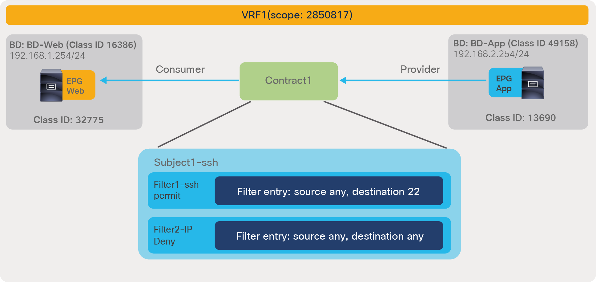
Example of policy-cam configuration with overlapping permit and deny rules
Pod1-Leaf1# show zoning-rule scope 2850817
+---------+--------+--------+----------+----------------+---------+---------+-------------------+----------+----------------------+
| Rule ID | SrcEPG | DstEPG | FilterID | Dir | operSt | Scope | Name | Action | Priority |
+---------+--------+--------+----------+----------------+---------+---------+-------------------+----------+----------------------+
| 4211 | 0 | 16386 | implicit | uni-dir | enabled | 2850817 | | permit | any_dest_any(16) |
| 4208 | 0 | 0 | implicit | uni-dir | enabled | 2850817 | | deny,log | any_any_any(21) |
| 4222 | 0 | 0 | implarp | uni-dir | enabled | 2850817 | | permit | any_any_filter(17) |
| 4221 | 0 | 15 | implicit | uni-dir | enabled | 2850817 | | deny,log | any_vrf_any_deny(22) |
| 4243 | 0 | 49158 | implicit | uni-dir | enabled | 2850817 | | permit | any_dest_any(16) |
| 4206 | 16390 | 32775 | 71 | uni-dir-ignore | enabled | 2850817 | tenant1:Contract1 | permit | fully_qual(7) |
| 4250 | 32775 | 16390 | 69 | bi-dir | enabled | 2850817 | tenant1:Contract1 | permit | fully_qual(7) |
| 4216 | 32775 | 16390 | 57 | bi-dir | enabled | 2850817 | tenant1:Contract1 | deny | fully_qual(7) |
| 4244 | 16390 | 32775 | 57 | uni-dir-ignore | enabled | 2850817 | tenant1:Contract1 | deny | fully_qual(7) |
+---------+--------+--------+----------+----------------+---------+---------+-------------------+----------+----------------------+
Table 22. Example of TCAM configuration with deny action and permit action within same zoning-rule priorities
| EtherType |
Protocol |
Source port |
Destination port |
Action |
| IP |
TCP |
Any |
22 |
Permit |
| IP |
Unspecified |
Any |
Any |
Deny |
Table 23. ACI forwarding action for traffic that matches both a deny rule and a more specific permit rule
| EtherType |
Protocol |
Source port |
Destination port |
Action |
| IP |
TCP |
Any |
22 |
Deny |
By changing the priority for the deny entry, the deny action can be deprioritized. The “show zoning-rule” output, below, is from an example with a deny priority set to “medium priority.”
Pod1-Leaf1# show zoning-rule scope 2850817
+---------+--------+--------+----------+----------------+---------+---------+-------------------+----------+----------------------+
| Rule ID | SrcEPG | DstEPG | FilterID | Dir | operSt | Scope | Name | Action | Priority |
+---------+--------+--------+----------+----------------+---------+---------+-------------------+----------+----------------------+
| 4211 | 0 | 16386 | implicit | uni-dir | enabled | 2850817 | | permit | any_dest_any(16) |
| 4208 | 0 | 0 | implicit | uni-dir | enabled | 2850817 | | deny,log | any_any_any(21) |
| 4222 | 0 | 0 | implarp | uni-dir | enabled | 2850817 | | permit | any_any_filter(17) |
| 4221 | 0 | 15 | implicit | uni-dir | enabled | 2850817 | | deny,log | any_vrf_any_deny(22) |
| 4243 | 0 | 49158 | implicit | uni-dir | enabled | 2850817 | | permit | any_dest_any(16) |
| 4206 | 16390 | 32775 | 71 | uni-dir-ignore | enabled | 2850817 | tenant1:Contract1 | permit | fully_qual(7) |
| 4250 | 32775 | 16390 | 69 | bi-dir | enabled | 2850817 | tenant1:Contract1 | permit | fully_qual(7) |
| 4216 | 32775 | 16390 | 57 | bi-dir | enabled | 2850817 | tenant1:Contract1 | deny | src_any_filter(13) |
| 4244 | 16390 | 32775 | 57 | uni-dir-ignore | enabled | 2850817 | tenant1:Contract1 | deny | src_any_filter(13) |
+---------+--------+--------+----------+----------------+---------+---------+-------------------+----------+----------------------+
The “show zoning-rule” output, below, shows an example with the deny priority set to “lowest priority.”
Pod1-Leaf1# show zoning-rule scope 2850817
+---------+--------+--------+----------+----------------+---------+---------+-------------------+----------+----------------------+
| Rule ID | SrcEPG | DstEPG | FilterID | Dir | operSt | Scope | Name | Action | Priority |
+---------+--------+--------+----------+----------------+---------+---------+-------------------+----------+----------------------+
| 4211 | 0 | 16386 | implicit | uni-dir | enabled | 2850817 | | permit | any_dest_any(16) |
| 4208 | 0 | 0 | implicit | uni-dir | enabled | 2850817 | | deny,log | any_any_any(21) |
| 4222 | 0 | 0 | implarp | uni-dir | enabled | 2850817 | | permit | any_any_filter(17) |
| 4221 | 0 | 15 | implicit | uni-dir | enabled | 2850817 | | deny,log | any_vrf_any_deny(22) |
| 4243 | 0 | 49158 | implicit | uni-dir | enabled | 2850817 | | permit | any_dest_any(16) |
| 4206 | 16390 | 32775 | 71 | uni-dir-ignore | enabled | 2850817 | tenant1:Contract1 | permit | fully_qual(7) |
| 4250 | 32775 | 16390 | 69 | bi-dir | enabled | 2850817 | tenant1:Contract1 | permit | fully_qual(7) |
| 4216 | 32775 | 16390 | 57 | bi-dir | enabled | 2850817 | tenant1:Contract1 | deny | any_any_filter(17) |
| 4244 | 16390 | 32775 | 57 | uni-dir-ignore | enabled | 2850817 | tenant1:Contract1 | deny | any_any_filter(17) |
+---------+--------+--------+----------+----------------+---------+---------+-------------------+----------+----------------------+
The “highest priority” option can be used to prioritize deny action if the deny action uses “any” filter, which has priority 9 by default.
In addition to a regular contract between consumer and provider EPGs, the following types of contracts can be used in Cisco ACI:
● Taboo contract: This is to deny and log traffic destined to specific EPG.
● Out-of-band (OOB) contract: This applies to out-of-band traffic from the management tenant.
The Taboo contract is used to deny and log traffic destined to a specific EPG. The Taboo contract has priority 5, which is higher than regular contracts.
The Taboo contract configuration location is at Tenant > Security > Contracts > Taboos. Similar to regular contracts between a consumer and a provider EPG, Taboo contracts contain subjects and filters but do not have other options such as service graphs and QoS policies.

Taboo contract configuration
The Taboo contract can be associated to one or more EPGs. The configuration location is at Tenant > Application Profiles > Application_Profile_name > Application EPGs > EPG_name.

Associate Taboo contract to an EPG
Figure 141 and the CLI output from the “show zoning-rule” command, below the figure, illustrates an example. The Web EPG and the App EPG have Contract1 to permit all IP traffic between them. Web EPG has a Taboo-Contract1 that denies SSH traffic destined to Web EPG. Thus, an endpoint in the Web EPG can talk to an endpoint in the App EPG and vice versa, except for the SSH traffic from an endpoint in the App EPG to an endpoint in the Web EPG.

Taboo contract example
Pod1-Leaf1# show zoning-rule scope 2850817
+---------+--------+--------+----------+----------------+---------+---------+-------------------+----------+----------------------+
| Rule ID | SrcEPG | DstEPG | FilterID | Dir | operSt | Scope | Name | Action | Priority |
+---------+--------+--------+----------+----------------+---------+---------+-------------------+----------+----------------------+
| 4211 | 0 | 16386 | implicit | uni-dir | enabled | 2850817 | | permit | any_dest_any(16) |
| 4208 | 0 | 0 | implicit | uni-dir | enabled | 2850817 | | deny,log | any_any_any(21) |
| 4222 | 0 | 0 | implarp | uni-dir | enabled | 2850817 | | permit | any_any_filter(17) |
| 4221 | 0 | 15 | implicit | uni-dir | enabled | 2850817 | | deny,log | any_vrf_any_deny(22) |
| 4243 | 0 | 49158 | implicit | uni-dir | enabled | 2850817 | | permit | any_dest_any(16) |
| 4205 | 0 | 32775 | 5 | uni-dir | enabled | 2850817 | | deny | black_list(5) |
| 4244 | 16390 | 32775 | 57 | uni-dir-ignore | enabled | 2850817 | tenant1:Contract1 | permit | fully_qual(7) |
| 4216 | 32775 | 16390 | 57 | bi-dir | enabled | 2850817 | tenant1:Contract1 | permit | fully_qual(7) |
+---------+--------+--------+----------+----------------+---------+---------+-------------------+----------+----------------------+
The red-highlighted rule (Rule ID 4205) is added by the Taboo contract. The priority of rule created by Taboo contracts have priority 5, which is higher than a regular contract Contract1 between Web EPG and App EPG. Thus, SSH traffic destined to Web EPG from any EPG is denied. Log is not enabled in rules created by Taboo contract. Log can be enabled at filters in a subject in the Taboo contract. Please see the subsection titled “Log” for more information.
Out-of-band (OOB) contracts
An administrator can connect to the APICs and the leaf nodes and spine nodes of an ACI fabric through in-band or out-of-band connectivity. The relevant configurations can be found in tenant mgmt (management). Out-of-band access refers to access through the management port (mgmt0).
Out-of-band contracts are the Cisco ACI equivalent of the NX-OS access-group for the mgmt0 port (https://www.cisco.com/c/en/us/td/docs/switches/datacenter/sw/best_practices/cli_mgmt_guide/cli_mgmt_bp/connect.html#wp1055200). In Cisco ACI, access control is performed through EPGs and contracts; this is no different for out-of-band management access, except that the out-of-band EPGs and contracts are different objects from the regular EPGs and contracts.
Out-of-band contracts are a different object (vzOOBBrCP) from regular contracts and can only be provided by special EPGs, the out-of-band EPGs (mgmtOoB), and can only be consumed by a special “L3 external,” an L3Out EPG called the External Management Instance Profile (mgmtInstP).
Assuming that you want to define the same security policy for APICs, leaf nodes, and spine nodes, the configuration of out-of-band management would include the following steps:
● Assign all the APICs, leaf nodes, and spine nodes to the same out-of-band EPG (for instance, the default one): This is done either through a Static Node Management Address configuration, where you define both the IP to give to the ACI node and which out-of-band EPG it belongs to, or through Managed Node Connectivity Groups (if you want to just provide a pool of IP addresses that ACI assigns to the nodes).
● Define the list of which management hosts can access APIC, leaf nodes, and spine nodes: This is modeled in a way that is similar to an L3Out EPG called the External Management Instance Profile (mgmtInstP).
● Define the out-of-band contracts (vzOOBBrCP) that control which protocol and ports can be used by the above hosts to connect to the APIC, leaf nodes, and spine nodes.
● Provide the out-of-band contract from the out-of-band EPG and consuming the contract from the External Management Instance Profile.
Figure 142 illustrates the configuration of out-of-band management in the mgmt tenant. Notice that the name of the default Out-of-Band EPG is “default,” just like the name of the default In-band EPG, but these are two different objects so the names can be identical.

Out-of-band management configuration in the mgmt tenant
The out-of-band contract can be defined by going to the following configuration location: Tenant common (or mgmt) > Contracts > Out-of-Band Contracts.
The contract, as you notice, is not defined as a normal contract. The configuration can be performed in the common tenant and can be used from the mgmt. tenant, or you can simply configure the contract directly in tenant mgmt. The scope of this contract can be set to a VRF; there is no need to set it to another value. The definition of the contract filters itself does not differ from the definition of other contracts; you can use the same filters defined for regular contracts, for instance.
It is possible that you may want to define out-of-band management to allow, for instance, only SSH to the spine and leaf nodes and HTTPS and SSH to the APIC. In that case, you need to perform the following configurations:
● Create two out-of-band EPGs (for example, oob-APIC-EPG and oob-leaf-and-spine-EPG).
● Define the Node Management Addresses with the correct association of the nodes to the out-of-band EPGs (For example, you would assign node-1, node-2, node-3 with oob-APIC-EPG, and the leaf and spine nodes to oob-leaf-and-spine-EPG.)
● Define one external management instance profile (or more, if you need to create different security policies for different management hosts); for instance you can create an external management instance called ext-mgmt-servers.
● Define two out-of-band contracts one for SSH only (called, here, “ssh-only”) and another one for HTTPS/SSH (“https-ssh”).
● Configure oob-APIC-EPG to provide “https-ssh”, oob-leaf-and-spine-EPG to provide “ssh-only”, and the external management instance ext-mgmt-servers to consume both “https-ssh” and “ssh-only”.
Note: The log directive cannot be used in conjunction with an out-of-band management contract. Only permit and deny contract actions are supported for the Management EPGs: Out-of-Band Management EPG and In-Band Management EPG.
As each contract rule gets programmed, EPG pairs with their associated filter entries will begin to consume Policy CAM (Content-Addressable Memory) on the switches. While designing security rules with EPGs and contracts, it is thus important to keep in mind the scale optimizations that Cisco ACI offers and to understand when and if reusing contracts can help reduce the TCAM utilization.
Note: Reusing the same contract across multiple EPGs without understanding the resulting zoning rules can result in flows that are allowed unexpectedly.
This section explains contract scalability considerations, recommendation, and the following Cisco ACI features to manage and optimize the policy-cam utilization:
● The ability to configure the leaf hardware to offer more space for the policy-cam compared to other hardware entries (for instance, compared to the Longest Prefix Match [LPM] table).
● Automatic optimization for filter ranges with -EX leaf nodes and newer.
● The ability to compress bidirectional entries or contracts that are reused multiple times.
● The ability to allocate hardware resources only on leaf nodes that require them.
General recommendation to increase efficiency and simplify ACI contracts
This sub-section summarizes a list of configurations generally recommended to increase efficiency and simplify ACI contracts. Please note that some may not be valid for a particular deployment scenario and please refer related sections in this document to understand what each configuration option does and its considerations.
1. If you don’t need any contract enforcement in a VRF, use Unenforced mode on the VRF.
2. If you don’t need any contract enforcement for sets of EPGs in a VRF, but still need contract enforcement for some EPGs, consider using the following options instead of individual contracts between many EPGs:
● If you use an ACI version that is earlier than 5.2(1) and if the number of EPGs that don’t need enforcement at all (i.e. in the Preferred Group) is higher than the EPGs that are outside, then use Preferred Group instead of specific contracts.
● If a set of EPGs have the same security requirement, use ESGsS with the ability to match EPGs to consolidate those EPGs.
● If you have a common security rule that is applicable to all of EPGs in a VRF, use vzAny-to-EPG and/or vzAny-to-vzAny contract.
If you need to deny specific traffic, use contracts with deny action in addition to permit rules above.
3. If possible, use the following configuration options:
● EPG: use “On-demand” instead of “Immediate” for Deployment Immediacy.
● Contract: set contract scope accordingly to avoid unnecessary TCAM consumption: Global, Tenant, VRF or Application Profile. When a contract is provided and/or consumed by vzAny, do NOT use “Application Profile” contract scope.
● Contract subject: use Apply Both Directions and Reverse Filter Ports instead of creating separate filters or contracts for consumer-provider and provider-consumer.
● Filter entry: use “any” or consolidate the port ranges in as few contiguous ranges as possible, to minimize the use of a lot of filter entries, and group filter entries under a single filter instead of spreading them across multiple filters.
4. If you have individual contracts with multiple EPGs or contract inheritance, please note that one configuration change could increase a lot of TCAM consumption. If possible, avoid such a design that one configuration will affect many objects. For example, if you have a contract between 100 consumer EPGs and 100 provider EPGs, one contract filter could add about 10K zoning-rule rules, which will also take time to update policies on leaf switches. It’s recommended to take advantage of vzAny or ESG instead of having individual contracts with many EPGs.
Another example is multiple filter entries in a filter. If one filter has multiple filter entries, though zoning-rule is created per filter, adding the filter to a contract consumes multiple TCAM entries.
Tile profiles
The hardware of -EX, -FX, FX2, -GX leaf nodes or newer is based on a programmable hardware architecture. The hardware is made of multipurpose “tiles,” where each tile can be used to perform routing functions or filtering functions, and so on. Starting with Cisco APIC Release 3.0, the administrator can choose to which function to allocate more tiles based on predefined profiles.
Note: The profile functionality is available on the -EX, -FX, -FX2, and -GX leaf nodes.
The functions whose scale is configurable through the use of tiles are:
● The MAC address table scalability
● The IPv4 scalability
● The IPv6 scalability
● The Longest Prefix Match (LPM) table scalability
● The Policy Cam scalability (for contracts/filtering)
● The space for Routed Multicast entries
The default profile (called also “dual stack”) allocates the hardware as follows:
● MAC address table scalability: 24K entries
● The IPv4 scalability: 24K entries
● The IPv6 scalability: 12K entries
● The Longest Prefix Match (LPM) table scalability: 20K entries
● The Policy Cam scalability (for contracts/filtering): 64K entries
● Multicast: 8K entries
A profile that has more scale for the policy-cam is, for instance, the “High Policy” profile for specific -FX and -GX leaf nodes, which provides 256K of policy-cam entries.
Table 24. Tile profile comparison
| Tile profile |
Cisco ACI release when first introduced |
Endpoint MAC |
Endpoint IPv4 |
Endpoint IPv6 |
LPM |
Policy |
Multicast |
| Default |
Release 3.0 |
24K |
24K |
12K |
20K (IPv4) 10k (IPv6) |
61K (Cisco ACI Release 3.0) 64K (Cisco ACI Release 3.2) |
8K (Cisco ACI Release 3.0) |
| IPv4 |
Release 3.0 |
48K |
48K |
0 |
38K (IPv4) 0 (IPv6) |
61K (Cisco ACI Release 3.0) 64K (Cisco ACI Release 3.2) |
8K (Cisco ACI Release 3.0) |
| High dual stack for: EX, -FX2 |
Release 3.1 |
64k |
64k |
24K |
38K (IPv4) 19K (IPv6) |
8K (Cisco ACI Release 3.1) |
0 (in Cisco ACI Release 3.1) 512 (in Cisco ACI Release 3.2) |
| High dual stack for: FX, -GX |
Release 3.1 (FX only) |
64K |
64K |
24K (ACI Release 3.1) 48K (ACI Release 3.2) |
38K (IPv4) 19K (IPv6) |
8K (Cisco ACI Release 3.1) 128K (Cisco ACI Release 3.2) |
0 (in Cisco ACI Release 3.1) 512 (in Cisco ACI Release 3.2) 32K (in Cisco ACI Release 4.0) |
| High LPM |
Release 3.2 |
24K |
24K |
12K |
128k (IPv4) 64k (IPv6) |
8K |
8K |
| High Policy (Cisco Nexus 93180YC-FX and Cisco Nexus 93600CD-GX with 32GB of RAM only) |
Release 4.2 |
24K |
24K |
12K |
20K (IPv4) 10k (IPv6) |
256K |
8K |
Note: For more information about the scale profiles, please refer to this page: https://www.cisco.com/c/en/us/td/docs/switches/datacenter/aci/apic/sw/kb/b_Cisco_APIC_Forwarding_Scale_Profile_Policy.html.
and to the scalability guide:
The configuration of the hardware profiles can be performed at Fabric > Access Policies > Switches > Leaf Switches > Policy Groups > Forwarding Scale Profile Policy, as illustrated in Figure 143.

Configuration of the Forwarding Scale Profile
Note: You need to reboot the leaf after changing the hardware profile.
You can also set the forwarding scale profile from the capacity dashboard. You should use this second approach with caution, because when you modify the leaf profile from the capacity dashboard, the GUI selects the profile that is already associated with the leaf that you chose. Normally, the profile that is associated with all of the leaf nodes is the “default” one; therefore, if you modify one, you will modify the hardware profile for all of the leaf nodes. In order to prevent this operational mistake, it would be a good practice to configure a non-default policy-group for either all of the leaf nodes or per group of leaf nodes that share the same use/characteristics.
Optimizations in cloud-scale Cisco Nexus leaf nodes
This white paper focuses on the use of leaf nodes based on the Cloud Scale ASIC, which includes the leaf nodes with names ending in -EX, -FX, -FX2, -FXP, -GX. This hardware has evolved significantly from the first-generation leaf nodes (Cisco Nexus 9396PX Switch, Cisco Nexus 93128TX Switch, and so on) to include several optimizations in the policy-cam. These optimizations are not only for scaling, due to the allocation of tiles, but also for the handling of:
● L4 port ranges (for instance, a security rule matching TCP with L4 ports ranging from 6000 to 6063).
● Bidirectional contracts (bidirectional rule compression).
● Reuse of the same contract among multiple EPG pairs (policy table compression).
L4 port ranges in traditional hardware have been a source of scalability concerns because they would be using some limited hardware resources (called Logical Operation Units [LOUs]), and then, once the hardware limit was exceeded, the range would be expanded into multiple entries, thus taking a significant amount of space in the TCAM.
Note: For more information about this issue with traditional switches, please refer to: https://community.cisco.com/t5/networking-documents/acl-tcam-and-lous-in-catalyst-6500/ta-p/3115339
In the case of ACI leaf nodes, starting with -EX leaf nodes and newer, L4 operation ranges use one single entry in the TCAM.
The section titled Enable Policy Compression, and the next section, below, cover the other two optimizations: bidirectional contracts and reuse of filters with contract reuse.
Policy compression
With -EX leaf nodes and -FX leaf nodes and newer, it is possible to optimize the usage of the policy-cam as described in the section titled Enable Policy Compression.
In summary, by configuring the option to perform compression at the filter level configuration, Cisco ACI optimizes the policy-cam usage depending on the capabilities offered by the hardware:
● With -EX, -FX, -FX2, -FXP, -FX3, -GX and -GX2 leaf nods, ACI is able to use a single policy-cam entry to perform both directions of the lookup of a bidirectional contract.
● With -FX, -FX2, -FXP, -FX3, -GX and -GX2 leaf nodes, ACI can reallocate the policy-cam to carve out a policy-group label table where the EPG pairs are stored together with a pointer to the policy-cam portion that has the filters. This allows the reuse of filters in case the same contract is reused multiple times between EPG pairs.
The carving of the policy-cam for compression reserves some space for the EPG pairs’ programming. For a default profile, this means that 10,000 entries of policy-cam space are used for EPG pairs pointing to label entries. The space required for EPG pairs and labels is much less than a full entry programmed with EPG class IDs and filters. For instance, with 10,000 entries of policy-cam, ACI can accommodate 20,000 EPG pairs. This means that the remaining 54,000 can be used for non-compressed entries and for filter entries that are reused multiple times.
For a high dual stack profile, ACI allocates 20,000 entries for the policy-group table and keeps 108,000 entries for non-compressed contracts and for filters pointed from the policy-group table (i.e. filters used by compressed entries.) This results in the capacity to store 40,000 EPG pairs with compressed contracts.
ACI carves the policy-cam for policy-group labels only if there are contracts that include filters with compression.
One of the key points to remember for the filter reuse optimization is that even if the configuration is at the filter level, ACI can configure the indirection only if the same contract is reused multiple times.
The following list provides a few additional important points about the filter-reuse compression feature:
● A contract can include both filters with compression enabled, and filters without compression enabled. This is compatible with compression: the entries that have compression enabled will be referred to by the policy-group label table; the other entries will be programmed normally.
● The optimization is applied for the rules that are present in re-used contracts. ACI is not going to compare the filters across different contracts in order to figure out whether it is possible to reuse them. Prior to APIC Release 5.0, if a contract is re-used across VRFs, the optimization works in each VRF independently. Starting from APIC Release 5.0, the optimization is applied across VRFs if the same contract is reused. For example, if multiple EPGs in different VRFs and/or different tenants reuse the same contract in common tenant, ACI is able to compress the contract filters by reusing them. The use of contract scope set to “Application”, “VRF” or “Tenant” can be used to avoid un-intended communication while the optimization still takes effect.
Resolution and deployment immediacy
Cisco ACI can optimize the use of hardware and software resources by programming the hardware of a given leaf with VRFs, bridge domains, SVIs, EPGs, and contracts only if endpoints are present in the EPG of interest on that leaf. This optimization is configurable as two separate options: Resolution Immediacy and Deployment Immediacy.
These options are configurable as part of the EPG configuration, as follows:
● For physical domains, the Deployment Immediacy option is configured as part of the EPG static port configuration.
● For VMM domains, the Resolution Immediacy and Deployment Immediacy options are configured as part of the EPG domain configuration.
The two options control different aspects of the hardware programming:
● Resolution Immediacy: This option controls when VRF, bridge domains, and SVIs are programmed on the leaf nodes.
● Deployment Immediacy: This option controls when contracts are programmed in the hardware.
The options for Resolution Immediacy (that is, for programming of the VRF, bridge domain, and SVI) are as follows:
● Pre-provision: This option means that the VRF, bridge domain, SVI, and EPG VLAN mappings are configured on the leaf nodes based on where the domain (or, to be more precise, the attachable access entity profile) is mapped within the fabric access configuration. If an EPG (in this example, “EPG1”) is associated with a VMM domain (“VMM domain1”), the bridge domain and the VRF to which EPG1 refers are instantiated on all of the leaf nodes where the VMM domain1 is configured. If another EPG (“EPG2”) is also associated with VMM domain1, the bridge domain and VRF that EPG2 refers to are also instantiated on all the leaf nodes where this VMM domain is configured.
● Immediate: This option means that the VRF, bridge domain, SVI, and EPG VLAN mappings are configured on a leaf as soon as a hypervisor that is connected to this leaf is attached to an APIC VMM virtual distributed switch. A discovery protocol, such as Cisco Discovery Protocol (CDP) and LLDP (Link Layer Discovery Protocol) (or the OpFlex protocol), is used to form the adjacency and discover to which leaf the virtualized host is attached. If EPG1 and EPG2 are associated with VMM domain1, the bridge domains and the VRFs to which these EPGs refer are instantiated only on the leaf node(s) where the host is attached.
● On Demand: This option means that the VRF, bridge domain, SVI, and EPG VLAN mappings are configured on a leaf switch only when a hypervisor that is connected to this leaf is connected to a virtual switch managed by the APIC, and at least one virtual machine on the host is connected to a port group and EPG that is associated with this physical NIC and leaf. If a virtual machine vNIC is associated with an EPG1 whose physical NIC is connected to a leaf, only the VRF, bridge domain, and EPG VLAN related to EPG1 are instantiated on that leaf (and not the VRF, bridge domain and EPG VLAN related to EPG2)
The options for Deployment Immediacy (that is, for programming of the policy CAM) are as follows:
● Immediate: The policy CAM is programmed on the leaf as soon as the policy is resolved to the leaf (see resolution immediacy, above), regardless of whether the virtual machine on the virtualized host has sent traffic.
● On Demand: The policy CAM is programmed after the virtual machine sends the first packet, as soon as the first data-plane packet reaches the leaf to trigger an endpoint learning for the EPG. The policy CAM programming is maintained and updated while an endpoint is learned on the leaf, and also for a certain time interval even after the last endpoint for the given EPG aged out on the leaf. The interval is the longer between the BD bounce timer and the VRF bounce timer (BD and VRF relative to the EPG that the endpoint belongs to). The BD and VRF bounce timer configurations are found in the endpoint retention policy for the BD and VRF respectively.
The use of the deployment on-demand option can help significantly in reducing the policy-cam utilization.
Tables 25, 26, and 27 illustrate the configuration options.
Table 25. Resolution Pre-provision and hardware programming
| Resolution Immediacy |
Pre-provision |
|||
| Deployment Immediacy |
On Demand |
Immediate |
||
| Hardware resource |
VRF, bridge domain, and SVI |
Policy CAM |
VRF, bridge domain, and SVI |
Policy CAM |
| Domain associated to EPG |
On leaf nodes where AEP (Attachable Entity Profile) and domain are present |
- |
On leaf nodes where AEP and domain are present |
On leaf nodes where AEP and domain are present |
| Host discovered on leaf through CDP/LLDP |
Same as above |
- |
Same as above |
Same as above |
| Virtual machine associated with port group |
Same as above |
- |
Same as above |
Same as above |
| Leaf receives traffic |
Same as above |
On leaf where traffic arrives |
Same as above |
Same as above |
Table 26. Resolution immediate and hardware programming
| Resolution |
Immediate |
|||
| Deployment |
On Demand |
Immediate |
||
| Hardware resource |
VRF, bridge domain, and SVI |
Policy CAM |
VRF, bridge domain, and SVI |
Policy CAM |
| Domain associated to EPG |
- |
- |
-- |
|
| Host discovered on leaf through CDP/LLDP |
On leaf where host is connected |
- |
On leaf where host is connected |
On leaf where host is connected |
| Virtual machine associated with port group |
Same as above |
- |
Same as above |
Same as above |
| Leaf receives traffic |
Same as above |
On leaf where traffic arrives |
Same as above |
Same as above |
Table 27. Resolution on-demand and hardware programming
| Resolution |
On Demand |
|||
| Deployment |
On Demand |
Immediate |
||
| Hardware resource |
VRF, bridge domain, and SVI |
Policy CAM |
VRF, bridge domain, and SVI |
Policy CAM |
| Domain associated to EPG |
- |
- |
- |
- |
| Host discovered on leaf through CDP/LLDP |
- |
- |
- |
- |
| Virtual machine associated with port group |
On leaf where virtual machine is associated with the EPG |
- |
On leaf where virtual machine is associated with the EPG |
On leaf where virtual machine is associated with the EPG |
| Leaf receives traffic |
Same as above |
On leaf where traffic arrives |
Same as above |
Same as above |
Note: The On Demand option is compatible with vMotion migration of virtual machines and is based on the coordination between APIC and the VMM.
You can choose to use the Pre-provision option for Resolution Immediacy when you need to help ensure that resources on which the resolution depends are allocated immediately. This setting may be needed, for instance, when the management interface of a virtualized host is connected to the ACI leaf.
For all other virtual machines, using the On Demand option saves hardware resources.
Using vzAny
The concept of vzAny was discussed in this document in the “vzAny” section of this document.
vzAny can be leveraged to avoid using too many entries in the policy-cam or too many contracts from the validated limits.
The usual ways to use vzAny to achieve this goal are as follows:
● Use vzAny as a consumer of an EPG that provides services to all the EPGs under a given VRF, thus configuring one contract instead of using as many contracts as the consumer EPGs.
● Define global rules that apply to all of the traffic between all of the EPGs of a given VRF. As an example, you may have specific EPG-to-EPG rules which have higher priority (priority 7) than vzAny, and then a contract provided and consumed by vzAny for some traffic types that need to be allowed among all of the EPGs.
● The last approach could also be used to deploy a combination of Cisco ACI and one or multiple firewalls, where certain rules are configured on ACI with EPG-to-EPG contracts and other rules are defined on the firewalls. The rules that are applied by ACI in the hardware (EPG-to-EPG rules) have a higher priority. The vzAny-to-vzAny contract would have a redirect to a given firewall for all traffic that does not match these rules. The firewall would apply access control lists to the redirected traffic.
The use of preferred groups for scalability purposes is less obvious; this is because the configuration of the preferred group of a given VRF results in the creation of multiple deny rules for EPGs that are outside of the preferred group. This could potentially take a lot of space if there are many EPGs that are not included in the preferred group.
Contracts and filters validated scalability limits
In order to plan and design for Cisco ACI, you need also to consider the verified scalability guide, which is regularly updated at every new release.
At the time of this writing, the latest verified scalability guide is available at this location:
This guide includes information about the hardware scale as well as the scales related to control-plane processing.
The most relevant scalability parameters related to the configuration of EPGs are the following ones:
● EPGs per tenant: At the time of this writing, the validated number is a maximum of 4000 EPGs in a single tenant for a fabric with a single tenant, and a maximum of 500 EPGs per tenant in a fabric with multiple tenants.
● EPGs per leaf: Cisco ACI can have a maximum of 3960 EPGs on a given leaf if all of the EPGs are associated to the same bridge domain. If, instead, each EPG is associated to a bridge domain, the maximum number if 3960/2. In general, you can think of the limit in terms of EPG + BD <= 3960.
● EPGs per bridge domain: ACI can have a maximum of 3960 EPGs per BD on a given leaf, and a maximum of 4000 EPGs per bridge domain fabric-wide.
● Number of EPGs that consume or provide a given contract: The validated number is a maximum of 100 EPGs providing the same contract or a maximum of 100 EPGs consuming the same contract. The maximum number of consumers from a single EPG and single contract is 1000.*
● Overall number of EPGs per fabric: 21,000 EPGs with a Layer 2 fabric and 15,000 EPGs with a Layer 3 fabric, across all tenants.
● Number of uSeg EPGs (IP-based or MAC based): 4000 per leaf (tested with 500 base EPGs per leaf).
The most relevant scalability parameters related to the configuration of contracts are the following ones:
● Number of contracts per fabric: 10,000 contracts per fabric, 10,000 filters per fabric.
● Number of consumer EPGs x number of provider EPGs x number of filters in the contract <= 50,000.
The most relevant scalability parameters related to the configuration of vzAny are the following ones:
● Maximum number of contracts provided or consumed by vzAny within a VRF for nonshared services is 70.
● Maximum number of contracts consumed by vzAny for inter-VRF traffic shared services is 16.
These numbers can change at every release as the Quality Assurance (QA) department validates scenarios with more and more configurations, ensuring that the control plane remains responsive and that configuration changes do not become too slow as a result of the larger configurations. You are requested to deploy solutions based on the validated limits for the release that you are using.
Even if Cisco cannot test every single possible customer topology with all dimensions, when the scale requirements of your design seem to require more than the validated numbers, you can ask your Cisco contact to discuss these numbers with the QA department. Depending on the scale and complexity of your design, the QA department may be able to express an opinion on whether the scale requested is viable or not.
Filter entry with port range considerations
ACI is designed to use two hardware components for traffic filtering, one is commonly referred to as policy CAM and the other is referred to as overflow TCAM. ACI handles the programming of these two regions in a way that is completely transparent to the user in order to maximize capacity and minimize fragmentation.
When it comes to matching filter ranges, the policy CAM region can be programmed with one single entry regardless of the number of L4 ports contained in the range. The downside is that if there are too many individual range operations defined for an EPG pair (the rule of thumb is if there are more than four range operations per EPG pair), these entries may not be suited to be programmed in the policy CAM because they may cause too much fragmentation (due to the way that the policy CAM hardware is programmed).
In such cases, ACI may use the overflow TCAM instead. In the overflow TCAM, filter range operations take more than one entry because they are expanded algorithmically (algorithmic expansion produces fewer entries than incremental expansion: e.g. a range of 1024 to 65535 doesn’t result in 64512 entries, but 9 instead).
It is very possible that ACI programs a filter that has a range operation in the overflow TCAM and it may later move the filter configuration to the policy CAM as one entry if it makes sense to do so in terms of being able to use memory efficiently. In order to use the policy CAM capabilities of matching ranges with a single entry efficiently (i.e. in order to use the policy CAM for larger ranges rather than smaller ones), you realize that it is wiser to program filter ranges that consist of a limited number of ports (e.g. destination port range between 8080 and 8089) as individual entries rather than as a range, so that if at a later stage you need to configure a filter to match a range of many L4 ports (e.g. 1000 L4 ports), this can get programmed as one single entry in the policy CAM.
For this reason, starting from Cisco APIC Release 4.2, with -EX, -FX, FX2, -GX, or newer hardware versions, ACI switches expand a contract with a filter entry using a small port range (of 10 or fewer ports, such as 81-90) into multiple entries.
This means that the same configuration uses a different amount of policy CAM with Cisco APIC Release 4.2 and newer compared with previous releases. It is also possible that this change could increase policy CAM utilization after upgrading leaf nodes to Release 4.2 or later from a release prior to 4.2 if you have such filters.
In summary, the following port range—related considerations are important, particularly after Cisco APIC Release 4.2:
● Consolidate the port ranges in as few contiguous ranges as possible, to minimize the use of a lot of filter entries with port ranges that span ten or fewer ports.
● Use a small number of filter entries with a port range per EPG pair. The recommendation is four or fewer filter entries with a port range per EPG pair.
Note for advanced readers: If the usage of the overflow TCAM reaches 80% or more, APIC raises a fault. If the usage of main policy CAM is also high and you still have a plan to add more EPGs or contracts, you might need to explore an option for the scale optimization, such as using policy compression, using vzAny and the others explained in Scalability considerations. If instead the usage of main policy CAM is not high, you may just need to consider reducing the use of range operations. An immediate action is not always necessary because it is still possible that with additional contracts/filter configurations ACI may move entries from the overflow TCAM to the main policy CAM dynamically.
The usage of the special region overflow TCAM can be checked at the object “eqptcapacityPolOTCAMUsage” if needed.
In a future release, there will be an option to make the range handling configurable. This will be added as part of CSCvv41584.
Figure 144 and the CLI outputs below the figure illustrate an example with a filter entry that has a range containing eleven port numbers.

Policy CAM usage example: a filter entry with eleven port numbers
Pod1-Leaf1# show zoning-rule scope 2195459
+---------+--------+--------+----------+----------------+---------+---------+-------------------+----------+----------------------+
| Rule ID | SrcEPG | DstEPG | FilterID | Dir | operSt | Scope | Name | Action | Priority |
+---------+--------+--------+----------+----------------+---------+---------+-------------------+----------+----------------------+
| 4100 | 0 | 0 | implarp | uni-dir | enabled | 2195459 | | permit | any_any_filter(17) |
| 4098 | 0 | 49156 | implicit | uni-dir | enabled | 2195459 | | permit | any_dest_any(16) |
| 4101 | 0 | 15 | implicit | uni-dir | enabled | 2195459 | | deny,log | any_vrf_any_deny(22) |
| 4099 | 0 | 0 | implicit | uni-dir | enabled | 2195459 | | deny,log | any_any_any(21) |
| 4210 | 0 | 32771 | implicit | uni-dir | enabled | 2195459 | | permit | any_dest_any(16) |
| 4211 | 32778 | 49157 | 150 | bi-dir | enabled | 2195459 | tenant1:Contract1 | permit | fully_qual(7) |
| 4138 | 49157 | 32778 | 151 | uni-dir-ignore | enabled | 2195459 | tenant1:Contract1 | permit | fully_qual(7) |
+---------+--------+--------+----------+----------------+---------+---------+-------------------+----------+----------------------+
Pod1-Leaf1# show zoning-filter filter 150
+----------+-------+--------+-------------+------+-------------+----------+-------------+-------------+-----------+---------+-------+-------------+-------------+----------+
| FilterId | Name | EtherT | ArpOpc | Prot | ApplyToFrag | Stateful | SFromPort | SToPort | DFromPort | DToPort | Prio | Icmpv4T | Icmpv6T | TcpRules |
+----------+-------+--------+-------------+------+-------------+----------+-------------+-------------+-----------+---------+-------+-------------+-------------+----------+
| 150 | 150_0 | ip | unspecified | tcp | no | no | unspecified | unspecified | 90 | 100 | dport | unspecified | unspecified | |
+----------+-------+--------+-------------+------+-------------+----------+-------------+-------------+-----------+---------+-------+-------------+-------------+----------+
Pod1-Leaf1# vsh_lc -c "show system internal aclqos zoning-rules 4211" | grep -c "Tcam Total Entries"
1
The red-highlighted zoning-rule entries are created because of the contract (Rule ID 4211 with filter 150 and Rule ID 4138 with filter 151). Each filter has eleven ports. One entry is created for each direction in the zoning-rule outputs, and the actual policy CAM usage is one per entry. This could be more than one depending on hash efficiency with other rules pprogrammed on the leaf.
Figure 145 and the CLI outputs below the figure, illustrate an example with filter entry that has a range containing ten port numbers.

Policy CAM usage example: a filter entry with fewer than eleven port numbers
Pod1-Leaf1# show zoning-rule scope 2195459
+---------+--------+--------+----------+----------------+---------+---------+-------------------+----------+----------------------+
| Rule ID | SrcEPG | DstEPG | FilterID | Dir | operSt | Scope | Name | Action | Priority |
+---------+--------+--------+----------+----------------+---------+---------+-------------------+----------+----------------------+
| 4100 | 0 | 0 | implarp | uni-dir | enabled | 2195459 | | permit | any_any_filter(17) |
| 4098 | 0 | 49156 | implicit | uni-dir | enabled | 2195459 | | permit | any_dest_any(16) |
| 4101 | 0 | 15 | implicit | uni-dir | enabled | 2195459 | | deny,log | any_vrf_any_deny(22) |
| 4099 | 0 | 0 | implicit | uni-dir | enabled | 2195459 | | deny,log | any_any_any(21) |
| 4210 | 0 | 32771 | implicit | uni-dir | enabled | 2195459 | | permit | any_dest_any(16) |
| 4211 | 49157 | 32778 | 149 | uni-dir-ignore | enabled | 2195459 | tenant1:Contract1 | permit | fully_qual(7) |
| 4138 | 32778 | 49157 | 148 | bi-dir | enabled | 2195459 | tenant1:Contract1 | permit | fully_qual(7) |
+---------+--------+--------+----------+----------------+---------+---------+-------------------+----------+----------------------+
Pod1-Leaf1# show zoning-filter filter 148
+----------+-------+--------+-------------+------+-------------+----------+-------------+-------------+-----------+---------+-------+-------------+-------------+----------+
| FilterId | Name | EtherT | ArpOpc | Prot | ApplyToFrag | Stateful | SFromPort | SToPort | DFromPort | DToPort | Prio | Icmpv4T | Icmpv6T | TcpRules |
+----------+-------+--------+-------------+------+-------------+----------+-------------+-------------+-----------+---------+-------+-------------+-------------+----------+
| 148 | 148_0 | ip | unspecified | tcp | no | no | unspecified | unspecified | 91 | 100 | dport | unspecified | unspecified | |
+----------+-------+--------+-------------+------+-------------+----------+-------------+-------------+-----------+---------+-------+-------------+-------------+----------+
Pod1-Leaf1# vsh_lc -c "show system internal aclqos zoning-rules 4138" | grep -c "Tcam Total Entries"
10
The red-highlighted zoning-rule entries are created because of the contract (Rule ID 4211 with filter 149 and Rule ID 4138 with filter 148). Each filter has ten ports. Although only one entry is created for each direction in the zoning-rule output, the actual policy CAM usage is ten per entry.
Figure 146 and the CLI outputs below the figure, illustrate an example with a filter that has ranges containing eleven ports in total, but each filter entry has a range containing ten or fewer ports.

Policy CAM usage example: filter entries with ten or fewer port numbers for each
Pod1-Leaf1# show zoning-rule scope 2195459
+---------+--------+--------+----------+----------------+---------+---------+-------------------+----------+----------------------+
| Rule ID | SrcEPG | DstEPG | FilterID | Dir | operSt | Scope | Name | Action | Priority |
+---------+--------+--------+----------+----------------+---------+---------+-------------------+----------+----------------------+
| 4100 | 0 | 0 | implarp | uni-dir | enabled | 2195459 | | permit | any_any_filter(17) |
| 4098 | 0 | 49156 | implicit | uni-dir | enabled | 2195459 | | permit | any_dest_any(16) |
| 4101 | 0 | 15 | implicit | uni-dir | enabled | 2195459 | | deny,log | any_vrf_any_deny(22) |
| 4099 | 0 | 0 | implicit | uni-dir | enabled | 2195459 | | deny,log | any_any_any(21) |
| 4210 | 0 | 32771 | implicit | uni-dir | enabled | 2195459 | | permit | any_dest_any(16) |
| 4211 | 32778 | 49157 | 154 | bi-dir | enabled | 2195459 | tenant1:Contract1 | permit | fully_qual(7) |
| 4138 | 49157 | 32778 | 155 | uni-dir-ignore | enabled | 2195459 | tenant1:Contract1 | permit | fully_qual(7) |
+---------+--------+--------+----------+----------------+---------+---------+-------------------+----------+----------------------+
Pod1-Leaf1# show zoning-filter filter 154
+----------+-------+--------+-------------+------+-------------+----------+-------------+-------------+-----------+---------+-------+-------------+-------------+----------+
| FilterId | Name | EtherT | ArpOpc | Prot | ApplyToFrag | Stateful | SFromPort | SToPort | DFromPort | DToPort | Prio | Icmpv4T | Icmpv6T | TcpRules |
+----------+-------+--------+-------------+------+-------------+----------+-------------+-------------+-----------+---------+-------+-------------+-------------+----------+
| 154 | 154_0 | ip | unspecified | tcp | no | no | unspecified | unspecified | 91 | 100 | dport | unspecified | unspecified | |
| 154 | 154_1 | ip | unspecified | tcp | no | no | unspecified | unspecified | 90 | 90 | dport | unspecified | unspecified | |
+----------+-------+--------+-------------+------+-------------+----------+-------------+-------------+-----------+---------+-------+-------------+-------------+----------+
Pod1-Leaf1# vsh_lc -c "show system internal aclqos zoning-rules 4211" | grep -c "Tcam Total Entries"
11
The red-highlighted zoning-rule entries are created because of the contract (Rule ID 4211 with filter 154 and Rule ID 4138 with filter 155). Each filter has eleven ports in total, but each filter entry has ten or fewer ports. Even if only one entry is created for each direction in the zoning-rule output, the actual policy CAM usage is eleven; that is, ten + one.
Although the granularity of the security rule is eventually the same for the examples in Figures 144 and 146, the example in Figure 144 is more efficient for policy CAM consumption. Thus, it is recommended to consolidate the ranges into as few contiguous ranges as possible.
Contract re-use misconceptions and dos and don’ts
Cisco ACI provides the ability to reuse objects. For instance, you could define a filter once in a tenant and put the same filter definition in multiple contracts. This is a usability feature so that you do not have to enter the same configuration multiple times. Reusing the same filter in multiple contracts does not save space in the policy-cam. If the filter is defined in the common tenant, you could use the same filter from any tenant, and this would save configuration time for the administrator, because you could define a filter for HTTP and not have to rewrite the same filter rule in each and every tenant where you define the contract. Reusing filters is a useful operational simplification.
Similarly, you could define a contract and reuse it multiple times. However, differently from reusing a filter, reusing a contract can have traffic forwarding effects that differ from your intended configuration; this depends, among other things, on the scope of the contract. Please refer to the section titled “Contract scope” for more information about the scope configuration.
It is a common mistake to define a contract in the common tenant (with the scope set to global, for instance) and reuse it in different tenants. This creates VRF-sharing rules between the VRFs of the different tenants, thus enabling a communication path between the different tenants. Unless you want to achieve inter-tenant inter-VRF forwarding, you should refrain from reusing contracts from the common tenant that has the scope set to global. If you still think or want to define a contract in the common tenant for operational reasons, make sure to set the scope to tenant or VRF. In summary, it is recommended to define contracts inside the tenant where it needs to be used, unless there is a need to configure inter-tenant or inter-VRF communication.
A common misconception related to scale consists in putting contracts in the common tenant and then using the same contracts multiple times in different tenants in order to keep the configuration of the number of contracts within the stated limit of 10,000. This approach does not help in terms of scalability of the control plane, but it helps for scalability of the policy-cam utilization if Contract scope is set and Policy Compression is used. From a control plane perspective, considering the architecture of the APIC, it is more beneficial to have contracts in different tenants.
Monitoring scale and planning for scale
You can see how much hardware is consumed by the security configurations by using the Operations / Capacity Dashboard view in the APIC. As you can see in Figure 147, from the Capacity Dashboard you can see the policy-cam utilization of each leaf, and in case you have contract filters with compression, you can also see the policy-group label table utilization.

Capacity Dashboard
Note for advanced readers: the total policy-cam hardware space is used not only for Rules, but also for Labels. For example, in the case of High Policy Profile with GX switches where policy compression is implicitly enabled, 256K space is used for both Rules and Labels.
Another tool that can be useful to manage the policy-cam capacity utilization is the Cisco® Nexus Dashboard (ND). With ND Policy CAM Analyzer, you have the ability to select multiple “dimensions” in order to see how many policy-cam entries that a tenant is using, or a specific pair of EPGs, or a specific contract within that pair, or a specific filter. Figure 148 illustrates this point. At the top of the figure, you can see the selection of tenant(s), EPGs, and contracts performed by the administrator; at the bottom, you can see how many rules this specific portion of the ACI configuration is using on each leaf. ND Policy CAM Analyzer can also help you determine which contracts have not been used recently. This can assist you in making informed decisions about removing contracts that you suspect are no longer in use. By reviewing the hit count, you can identify contract entries that have not been hit in the last month. The cumulative number of hits is also shown, allowing you to monitor the longer-term usage of the contracts.
Note: For more information about Cisco ND Policy CAM Analyzer, please refer to https://www.cisco.com/c/en/us/td/docs/dcn/ndi/6x/articles-651/ndi-analysis-hub-aci.html#_policy_cam.

Using Cisco ND to manage policy-cam utilization
This section explains design examples that have a mix of configuration options described in this document, based on the following scenario (please refer to each section to understand what each option does).
Imagine that you are going to add a new tenant to your Cisco ACI fabric. You have an existing shared service in another tenant that a couple of EPGs in the new tenant need to access. You want the endpoints in the new tenant to be able to talk each other – with the exception of some combinations of EPGs: some of the endpoints need to be inspected by a firewall and some need to be denied by the ACI fabric. You will have new EPGs after the initial deployment, and you want to simplify the configuration.
Figure 149 illustrates the requirements:
● EPG1 in tenant1 needs to access EPG Shared in tenant-shared.
● IP traffic within the tenant1 VRF1 needs to be permitted with the following exceptions:
◦ UDP traffic between EPG1 and EPG2 is not allowed.
◦ TCP traffic between EPG2 and EPG3 needs to be inspected by the firewall.
● After the initial deployment, EPG4 is added, which has requirements that are similar those for to EPG1 but not exactly the same:
◦ EPG4 needs to access EPG Shared in tenant-shared.
◦ EPG4 needs to access other EPGs in the same VRF, except EPG2 and EPG3 via UDP.

EPG and contract requirements for the text scenario
The configuration steps explained in this document are as follows,
● Give access to a shared service in different tenant.
● Manage security policies within a tenant.
● Add more EPGs.
Each step is independent of the others.
This section does not cover how to create tenants, VRFs, BDs, EPGs, filters, and contracts. The assumption is that the items below are already configured.
● ACI fabric initial setup (such as discovering APIC, leaf, and spine).
● Access policy and domain configurations.
● Tenant, VRFs, BDs, EPG, filters, and contracts.
● Firewall initial setup and its configuration.
Give access to common shared service in a different tenant
The first requirement is that EPG1 needs to access EPG Shared in a different tenant. Figure 150 illustrates the design and overall configuration. EPG Shared in tenant-shared is the provider EPG, and EPG1 in tenant1 is the consumer EPG.
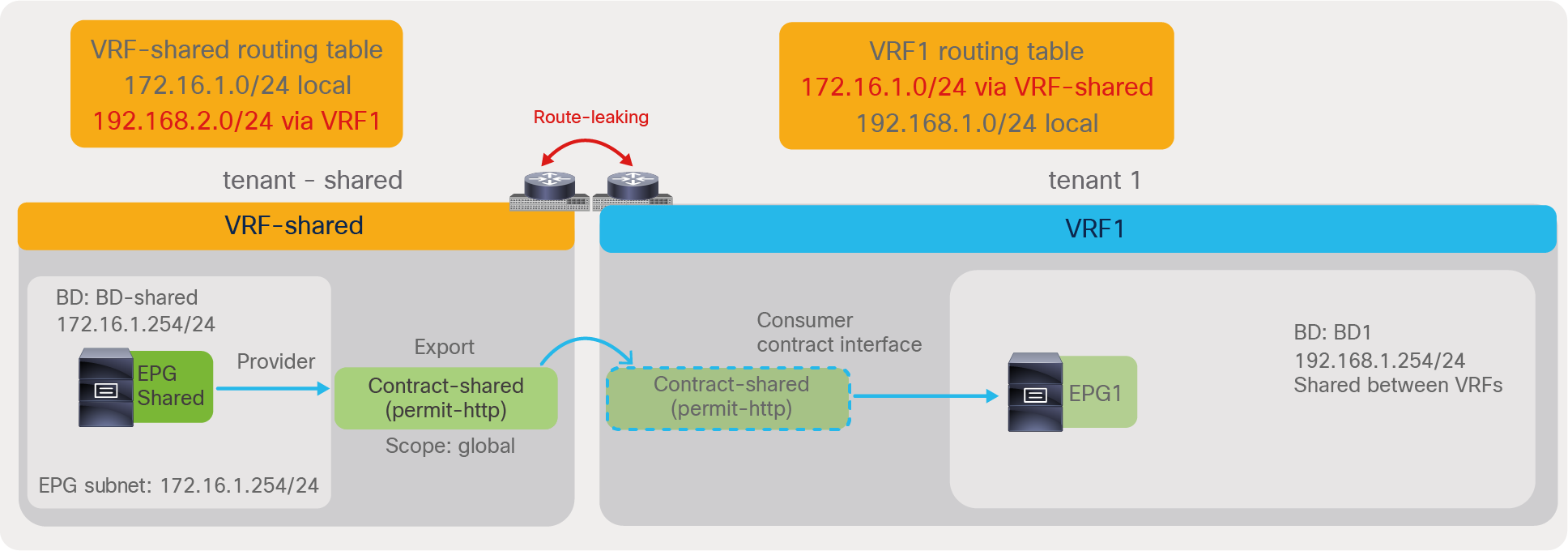
Shared service (Inter-tenant and inter-VRF contract)
The required configuration steps are as follows:
● Provider tenant (tenant-shared):
◦ Set “Global” scope in the contract defined in the provider tenant.
◦ Export the contract from the provider tenant to the consumer tenant.
◦ Configure the provider EPG subnet with “Shared between VRFs” scope.
● Consumer tenant (tenant1):
◦ Configure the consumer BD subnet with “Shared between VRFs” scope.
◦ Add the consumed contract interface to the consumer EPG.
Figures 151 and 152 summarize the required configurations in the provider tenant and the consumer tenant. Please see the Inter-VRF and inter-tenant contracts section for details.

Provider tenant configuration (tenant-shared)
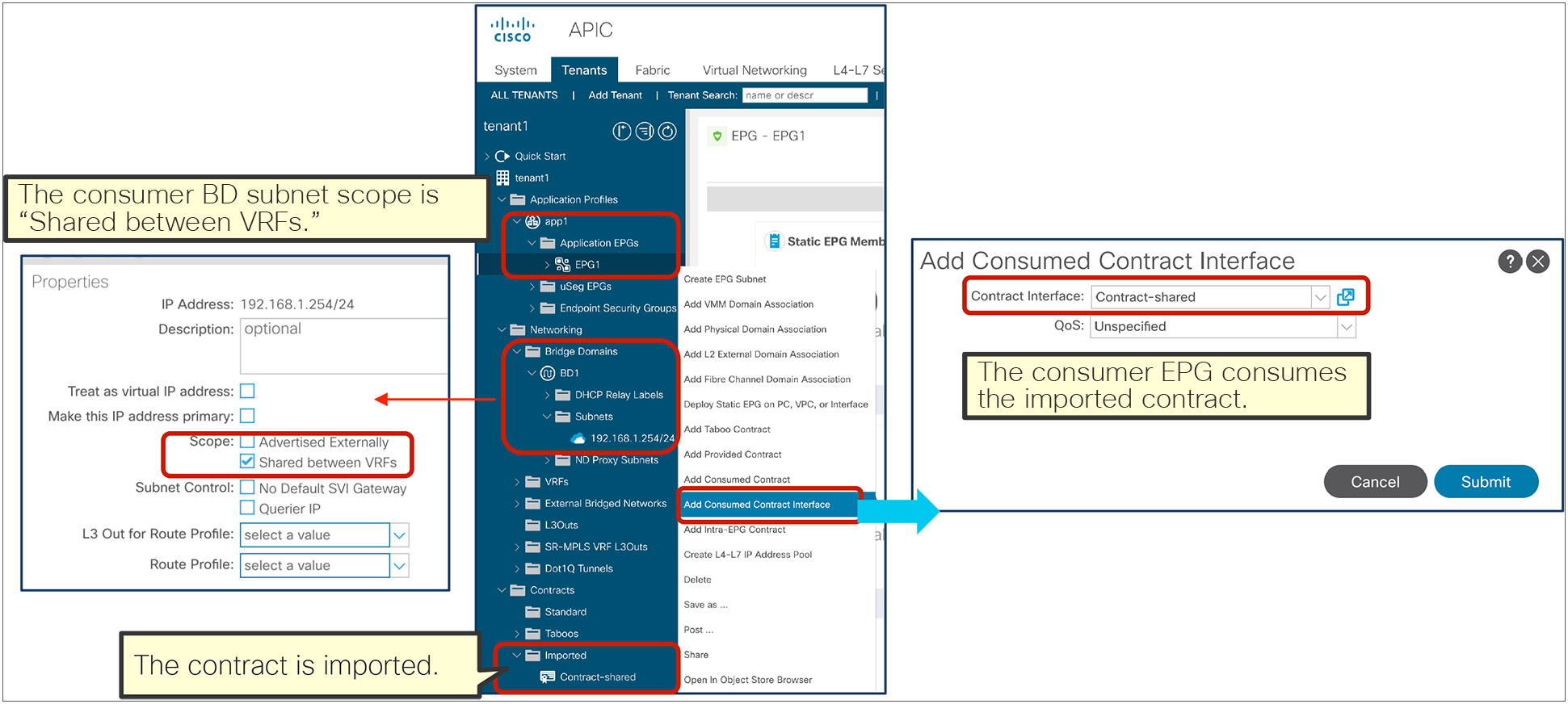
Consumer tenant configuration (tenant1)
Once a contract is defined between the EPGs, the routes are leaked between VRFs, and zoning rules are programmed. In the case of inter-VRF contracts, the contract is enforced on the consumer VRF, and the provider VRF has an implicit permit rule. The outputs from the “show ip route” and “show zoning-rule” commands, given below Figure 153, show the routing tables and zoning rules related to the network design illustrated in the figure.
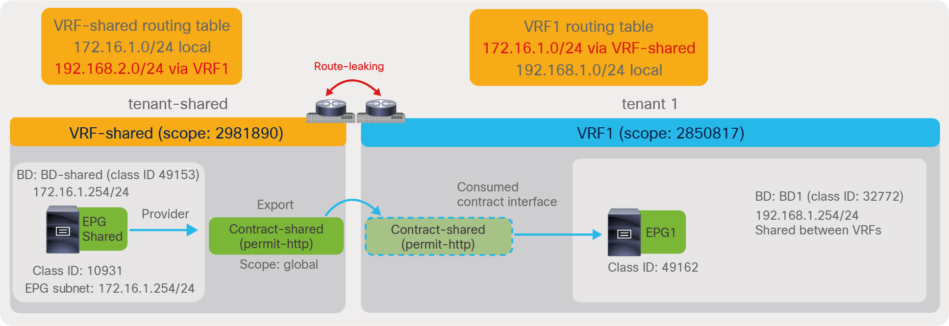
Shared service (inter-tenant and inter-VRF contract)
The “show ip route” output of VRF-shared in tenant-shared is as follows:
Pod1-Leaf1# show ip route vrf tenant-shared:VRF-shared
IP Route Table for VRF "tenant-shared:VRF-shared"
'*' denotes best ucast next-hop
'**' denotes best mcast next-hop
'[x/y]' denotes [preference/metric]
'%<string>' in via output denotes VRF <string>
172.16.1.0/24, ubest/mbest: 1/0, attached, direct, pervasive
*via 10.0.16.66%overlay-1, [1/0], 00:03:15, static, tag 4294967294
172.16.1.254/32, ubest/mbest: 1/0, attached, pervasive
*via 172.16.1.254, vlan103, [0/0], 00:09:00, local, local
192.168.1.0/24, ubest/mbest: 1/0, attached, direct, pervasive
*via 10.0.16.66%overlay-1, [1/0], 00:03:15, static, tag 4294967294
The red-highlighted route is leaked from VRF1 in tenant1.
The “show zoning-rule” output of VRF-shared in tenant-shared is as follows:
Pod1-Leaf1# show zoning-rule scope 2981890
+---------+--------+--------+----------+---------+---------+---------+------+-----------------+----------------------+
| Rule ID | SrcEPG | DstEPG | FilterID | Dir | operSt | Scope | Name | Action | Priority |
+---------+--------+--------+----------+---------+---------+---------+------+-----------------+----------------------+
| 4251 | 0 | 0 | implicit | uni-dir | enabled | 2981890 | | deny,log | any_any_any(21) |
| 4254 | 0 | 0 | implarp | uni-dir | enabled | 2981890 | | permit | any_any_filter(17) |
| 4228 | 0 | 15 | implicit | uni-dir | enabled | 2981890 | | deny,log | any_vrf_any_deny(22) |
| 4213 | 0 | 49153 | implicit | uni-dir | enabled | 2981890 | | permit | any_dest_any(16) |
| 4229 | 10931 | 14 | implicit | uni-dir | enabled | 2981890 | | permit_override | src_dst_any(9) |
+---------+--------+--------+----------+---------+---------+---------+------+-----------------+----------------------+
The red-highlighted entry with Rule ID 4229 is to permit traffic from EPG Shared to another VRF. As it is an implicit permit rule, the “policy applied bit” is not set, and policy is enforced on the consumer VRF.
The “show ip route” output of VRF1 in tenant1 is as follows:
Pod1-Leaf1# show ip route vrf tenant1:VRF1
IP Route Table for VRF "tenant1:VRF1"
'*' denotes best ucast next-hop
'**' denotes best mcast next-hop
'[x/y]' denotes [preference/metric]
'%<string>' in via output denotes VRF <string>
172.16.1.0/24, ubest/mbest: 1/0, attached, direct, pervasive
*via 10.0.16.66%overlay-1, [1/0], 00:01:02, static, tag 4294967294
192.168.1.0/24, ubest/mbest: 1/0, attached, direct, pervasive
*via 10.0.16.66%overlay-1, [1/0], 00:12:18, static, tag 4294967294
192.168.1.254/32, ubest/mbest: 1/0, attached, pervasive
*via 192.168.1.254, vlan99, [0/0], 00:12:18, local, local
The red-highlighted route is leaked from VRF-shared in tenant-shared.
The “show zoning-rule” output of VRF1 in tenant1 is as follows:
Pod1-Leaf1# show zoning-rule scope 2850817
+---------+--------+--------+----------+----------------+---------+---------+-------------------------------+----------+------------------------+
| Rule ID | SrcEPG | DstEPG | FilterID | Dir | operSt | Scope | Name | Action | Priority |
+---------+--------+--------+----------+----------------+---------+---------+-------------------------------+----------+------------------------+
| 4225 | 0 | 0 | implicit | uni-dir | enabled | 2850817 | | deny,log | any_any_any(21) |
| 4250 | 0 | 0 | implarp | uni-dir | enabled | 2850817 | | permit | any_any_filter(17) |
| 4206 | 0 | 15 | implicit | uni-dir | enabled | 2850817 | | deny,log | any_vrf_any_deny(22) |
| 4215 | 0 | 32772 | implicit | uni-dir | enabled | 2850817 | | permit | any_dest_any(16) |
| 4207 | 10931 | 0 | implicit | uni-dir | enabled | 2850817 | | deny,log | shsrc_any_any_deny(12) |
| 4231 | 10931 | 49162 | 9 | uni-dir-ignore | enabled | 2850817 | tenant-shared:Contract-shared | permit | fully_qual(7) |
| 4252 | 49162 | 10931 | 8 | bi-dir | enabled | 2850817 | tenant-shared:Contract-shared | permit | fully_qual(7) |
+---------+--------+--------+----------+----------------+---------+---------+-------------------------------+----------+------------------------+
The red-highlighted entries with Rule IDs 4231 and 4252 in tenant1 VRF1 are to permit traffic between EPG Shared and EPG1. Rule ID 4207 is to deny other traffic from EPG Shared.
Manage security policies within the tenant
Within the user tenant VRF, the requirement is that all IP traffic within tenant1 VRF1 needs to be permitted with some exceptions:
● UDP traffic between EPG1 and EPG2 is not allowed.
● TCP traffic between EPG2 and EPG3 needs to be inspected by a firewall.
Figure 154 illustrates the design and overall configuration. The vzAny-to-vzAny contract is used to permit all IP traffic within tenant1 VRF. The EPG1-to-EPG2 contract denies traffic between EPG1 and EPG2. EPG2-to-EPG3 contract has a redirect action (Service Graph with PBR) to forward traffic to a firewall.

Security policy within tenant (vzAny-to-vzAny, PBR, and deny action)
The required configuration steps are as follows:
● Configure vzAny for tenant1 VRF1 to provide and consume a vzAny-to-vzAny contract that has a permit IP filter.
● Configure the EPG1-to-EPG2 contract subject with a UDP filter entry with deny.
● Configure the EPG2-to-EPG3 contract subject with a TCP filter, and associate the subject with a Service Graph with PBR.
Figures 155, 156, and 157 summarize the required configurations in tenant1. Please see sections vzAny, Deny action, and L4-L7 Service Graph and Policy Based Redirect (PBR) for details.

vzAny for tenant1 VRF1 consumes and provides a vzAny-to-vzAny contract that has a permit IP filter
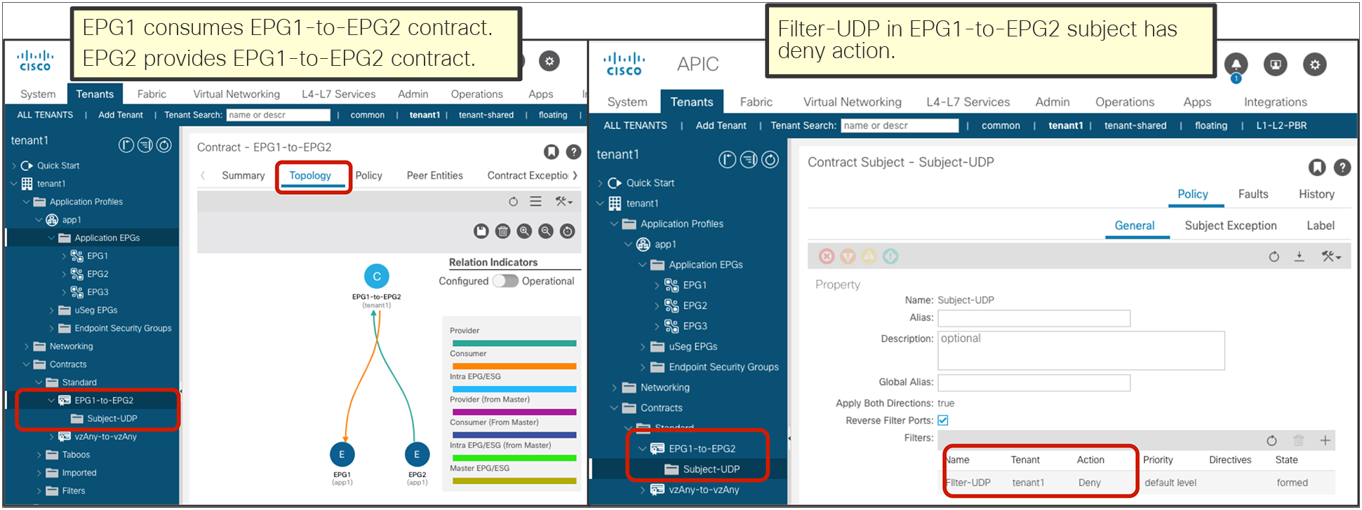
Set a deny action in the UDP filter entry in the EPG1-to-EPG2 contract subject

Configure the EPG2-to-EPG3 contract subject with a TCP filter, and associate this subject with a Service Graph with PBR
Once contracts are defined between the EPGs, zoning rules are programmed on tenant1 VRF1. The CLI output from the “show zoning-rule” command, given below Figure 158, shows the zoning rules that use class ID allocations illustrated in the figure.

Security policy within tenant (vzAny-to-vzAny, PBR, and deny action)
The “show zoning-rule” output of VRF1 in tenant1 is as follows:
Pod1-Leaf1# show zoning-rule scope 2850817
+---------+--------+--------+----------+----------------+---------+---------+-------------------------------+------------------+------------------------+
| Rule ID | SrcEPG | DstEPG | FilterID | Dir | operSt | Scope | Name | Action | Priority |
+---------+--------+--------+----------+----------------+---------+---------+-------------------------------+------------------+------------------------+
| 4225 | 0 | 0 | implicit | uni-dir | enabled | 2850817 | | deny,log | any_any_any(21) |
| 4250 | 0 | 0 | implarp | uni-dir | enabled | 2850817 | | permit | any_any_filter(17) |
| 4206 | 0 | 15 | implicit | uni-dir | enabled | 2850817 | | deny,log | any_vrf_any_deny(22) |
| 4215 | 0 | 32772 | implicit | uni-dir | enabled | 2850817 | | permit | any_dest_any(16) |
| 4207 | 10931 | 0 | implicit | uni-dir | enabled | 2850817 | | deny,log | shsrc_any_any_deny(12) |
| 4231 | 10931 | 49162 | 9 | uni-dir-ignore | enabled | 2850817 | tenant-shared:Contract-shared | permit | fully_qual(7) |
| 4252 | 49162 | 10931 | 8 | bi-dir | enabled | 2850817 | tenant-shared:Contract-shared | permit | fully_qual(7) |
| 4253 | 0 | 0 | 57 | uni-dir | enabled | 2850817 | tenant1:vzAny-to-vzAny | permit | any_any_filter(17) |
| 4260 | 49162 | 16392 | 12 | bi-dir | enabled | 2850817 | tenant1:EPG1-to-EPG2 | deny | fully_qual(7) |
| 4259 | 16392 | 49162 | 12 | uni-dir-ignore | enabled | 2850817 | tenant1:EPG1-to-EPG2 | deny | fully_qual(7) |
| 4249 | 32773 | 16392 | 32 | uni-dir | enabled | 2850817 | | permit | fully_qual(7) |
| 4226 | 49154 | 16392 | 32 | uni-dir-ignore | enabled | 2850817 | | redir(destgrp-3) | fully_qual(7) |
| 4261 | 16392 | 49154 | 32 | bi-dir | enabled | 2850817 | | redir(destgrp-3) | fully_qual(7) |
| 4258 | 32773 | 49154 | default | uni-dir | enabled | 2850817 | | permit | src_dst_any(9) |
+---------+--------+--------+----------+----------------+---------+---------+-------------------------------+------------------+------------------------+
Cisco ACI creates the entry with Rule ID 4253 for the vzAny-to-vzAny contract to permit IP traffic within the VRF. Entries with Rule IDs 4260 and 4259 are created by the EPG1-to-EPG2 contract to deny UDP traffic between EPG1 and EPG2. Entries with Rule IDs 4249, 4226, 4261, and 4258 are created by the EPG2-to-EPG3 contract with the Service Graph. The entries with Rule IDs 4226 and 4261 are to redirect traffic to the firewall. The entries with Rule IDs 4249 and 4258 are to permit traffic from the firewall to EPG2 and EPG3. The entry with Rule ID 4253 created by the vzAny-to-vzAny contract has a lower priority (priority 17); IP traffic within the VRF is permitted except for traffic that hits the rules created through user-defined contracts (which have priority 7 or 9).
Add more EPGs
After the initial deployment, EPG4 is added, which has requirements similar but not identical to EPG1:
● EPG4 needs to access the EPG Shared in tenant-shared.
● EPG4 needs to access other EPGs in the VRF, except EPG2 and EPG3 via UDP.
Figure 159 illustrates the design and overall configuration. EPG4 has the same security requirements as EPG1 to access the EPG Shared in tenant-shared and other EPGs in the same VRF, except EPG2 and EPG3 via UDP. By using EPG1 as the master EPG for EPG4, EPG4 can access EPG Shared in tenant-shared and other EPGs in VRF1, except EPG2 via UDP. In addition to this, UDP traffic between EPG3 and EPG4 needs to be denied. By configuring EPG3-to-EPG4 contract with a deny action for UDP traffic, UDP traffic between EPG3 and EPG4 will be denied. EPG1 can still communicate with EPG3 as the deny rule is not applicable to EPG1.
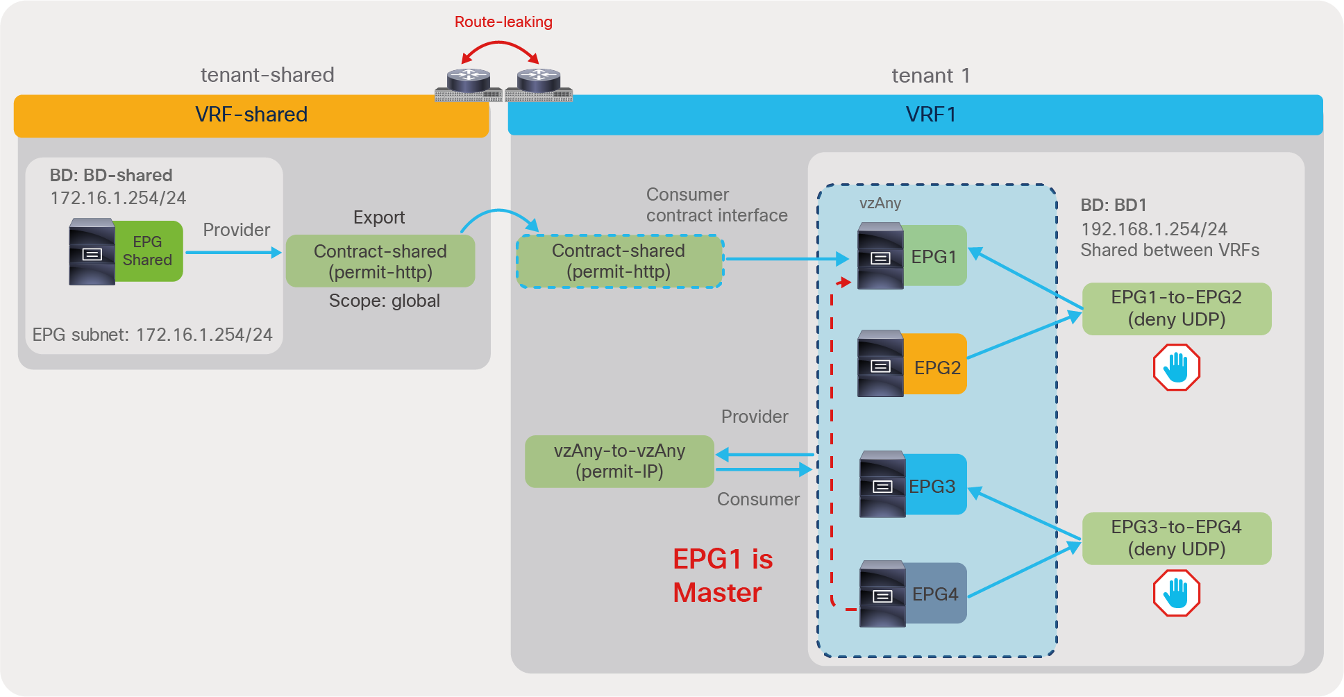
Contract inheritance
The required configurations are as follows:
● Configure EPG1 as EPG Contract Master for EPG4.
● Set a deny action in the UDP filter entry in the EPG3-to-EPG4 contract subject.
Figures 160 and 161 summarize the required configurations in tenant1. Please see sections “Contract inheritance” and “Deny action” for details.

Configure EPG Contract Master for EPG4

Set the deny action in the UDP filter entry in the EPG1-to-EPG2 contract subject
Once contracts are defined between the EPGs, zoning rules are programmed on tenant1 VRF1. The CLI output from the “show zoning-rule” command, shown below Figure 162, shows the zoning rules that use class ID allocations illustrated in the figure.

Adding EPG4 using Contract inheritance
The “show zoning-rule” output of VRF1 in tenant1 is as follows:
Pod1-Leaf1# show zoning-rule scope 2850817
+---------+--------+--------+----------+----------------+---------+---------+-------------------------------+------------------+------------------------+
| Rule ID | SrcEPG | DstEPG | FilterID | Dir | operSt | Scope | Name | Action | Priority |
+---------+--------+--------+----------+----------------+---------+---------+-------------------------------+------------------+------------------------+
| 4225 | 0 | 0 | implicit | uni-dir | enabled | 2850817 | | deny,log | any_any_any(21) |
| 4250 | 0 | 0 | implarp | uni-dir | enabled | 2850817 | | permit | any_any_filter(17) |
| 4206 | 0 | 15 | implicit | uni-dir | enabled | 2850817 | | deny,log | any_vrf_any_deny(22) |
| 4215 | 0 | 32772 | implicit | uni-dir | enabled | 2850817 | | permit | any_dest_any(16) |
| 4207 | 10931 | 0 | implicit | uni-dir | enabled | 2850817 | | deny,log | shsrc_any_any_deny(12) |
| 4231 | 10931 | 49162 | 9 | uni-dir-ignore | enabled | 2850817 | tenant-shared:Contract-shared | permit | fully_qual(7) |
| 4252 | 49162 | 10931 | 8 | bi-dir | enabled | 2850817 | tenant-shared:Contract-shared | permit | fully_qual(7) |
| 4253 | 0 | 0 | 57 | uni-dir | enabled | 2850817 | tenant1:vzAny-to-vzAny | permit | any_any_filter(17) |
| 4260 | 49162 | 16392 | 12 | bi-dir | enabled | 2850817 | tenant1:EPG1-to-EPG2 | deny | fully_qual(7) |
| 4259 | 16392 | 49162 | 12 | uni-dir-ignore | enabled | 2850817 | tenant1:EPG1-to-EPG2 | deny | fully_qual(7) |
| 4249 | 32773 | 16392 | 32 | uni-dir | enabled | 2850817 | | permit | fully_qual(7) |
| 4226 | 49154 | 16392 | 32 | uni-dir-ignore | enabled | 2850817 | | redir(destgrp-3) | fully_qual(7) |
| 4261 | 16392 | 49154 | 32 | bi-dir | enabled | 2850817 | | redir(destgrp-3) | fully_qual(7) |
| 4258 | 32773 | 49154 | default | uni-dir | enabled | 2850817 | | permit | src_dst_any(9) |
| 4257 | 16392 | 16393 | 12 | uni-dir-ignore | enabled | 2850817 | tenant1:EPG1-to-EPG2 | deny | fully_qual(7) |
| 4210 | 16393 | 16392 | 12 | bi-dir | enabled | 2850817 | tenant1:EPG1-to-EPG2 | deny | fully_qual(7) |
| 4262 | 16393 | 10931 | 8 | bi-dir | enabled | 2850817 | tenant-shared:Contract-shared | permit | fully_qual(7) |
| 4263 | 10931 | 16393 | 9 | uni-dir-ignore | enabled | 2850817 | tenant-shared:Contract-shared | permit | fully_qual(7) |
| 4264 | 16393 | 49154 | 12 | uni-dir-ignore | enabled | 2850817 | tenant1:EPG3-to-EPG4 | deny | fully_qual(7) |
| 4265 | 49154 | 16393 | 12 | bi-dir | enabled | 2850817 | tenant1:EPG3-to-EPG4 | deny | fully_qual(7) |
+---------+--------+--------+----------+----------------+---------+---------+-------------------------------+------------------+------------------------+
The red-highlighted entries for Rule IDs 4257, 4210, 4262, and 4263 are created by the Contract EPG Master configuration. EPG4 has the same contracts as EPG1; as a result, EPG4 can communicate with the Shared EPG and cannot communicate with EPG2. As EPG4 is part of vzAny in the VRF, IP traffic between other EPGs and EPG4 is permitted except for UDP traffic between EPG3 and EPG4, because of the (also red-highlighted) entries for Rule IDs 4264 and 4265 that are created by the EPG3-to-EPG4 contract.
Verification of the configurations
Figure 163 illustrates the summary of configurations in this section followed by the “show zoning-rule” command output on VRF-shared in tenant-shared-service and VRF1 in tenant1.

Combined configurations
The “show zoning-rule” output of VRF-shared in tenant-shared is as follows:
Pod1-Leaf1# show zoning-rule scope 2981890
+---------+--------+--------+----------+---------+---------+---------+------+-----------------+----------------------+
| Rule ID | SrcEPG | DstEPG | FilterID | Dir | operSt | Scope | Name | Action | Priority |
+---------+--------+--------+----------+---------+---------+---------+------+-----------------+----------------------+
| 4251 | 0 | 0 | implicit | uni-dir | enabled | 2981890 | | deny,log | any_any_any(21) |
| 4254 | 0 | 0 | implarp | uni-dir | enabled | 2981890 | | permit | any_any_filter(17) |
| 4228 | 0 | 15 | implicit | uni-dir | enabled | 2981890 | | deny,log | any_vrf_any_deny(22) |
| 4213 | 0 | 49153 | implicit | uni-dir | enabled | 2981890 | | permit | any_dest_any(16) |
| 4229 | 10931 | 14 | implicit | uni-dir | enabled | 2981890 | | permit_override | src_dst_any(9) |
+---------+--------+--------+----------+---------+---------+---------+------+-----------------+----------------------+
The “show zoning-rule” output of VRF1 in tenant1 is as follows:
Pod1-Leaf1# show zoning-rule scope 2850817
+---------+--------+--------+----------+----------------+---------+---------+-------------------------------+------------------+------------------------+
| Rule ID | SrcEPG | DstEPG | FilterID | Dir | operSt | Scope | Name | Action | Priority |
+---------+--------+--------+----------+----------------+---------+---------+-------------------------------+------------------+------------------------+
| 4225 | 0 | 0 | implicit | uni-dir | enabled | 2850817 | | deny,log | any_any_any(21) |
| 4250 | 0 | 0 | implarp | uni-dir | enabled | 2850817 | | permit | any_any_filter(17) |
| 4206 | 0 | 15 | implicit | uni-dir | enabled | 2850817 | | deny,log | any_vrf_any_deny(22) |
| 4215 | 0 | 32772 | implicit | uni-dir | enabled | 2850817 | | permit | any_dest_any(16) |
| 4207 | 10931 | 0 | implicit | uni-dir | enabled | 2850817 | | deny,log | shsrc_any_any_deny(12) |
| 4253 | 0 | 0 | 57 | uni-dir | enabled | 2850817 | tenant1:vzAny-to-vzAny | permit | any_any_filter(17) |
| 4260 | 49162 | 16392 | 12 | bi-dir | enabled | 2850817 | tenant1:EPG1-to-EPG2 | deny | fully_qual(7) |
| 4259 | 16392 | 49162 | 12 | uni-dir-ignore | enabled | 2850817 | tenant1:EPG1-to-EPG2 | deny | fully_qual(7) |
| 4249 | 32773 | 16392 | 32 | uni-dir | enabled | 2850817 | | permit | fully_qual(7) |
| 4226 | 49154 | 16392 | 32 | uni-dir-ignore | enabled | 2850817 | | redir(destgrp-3) | fully_qual(7) |
| 4261 | 16392 | 49154 | 32 | bi-dir | enabled | 2850817 | | redir(destgrp-3) | fully_qual(7) |
| 4258 | 32773 | 49154 | default | uni-dir | enabled | 2850817 | | permit | src_dst_any(9) |
| 4257 | 16392 | 16393 | 12 | uni-dir-ignore | enabled | 2850817 | tenant1:EPG1-to-EPG2 | deny | fully_qual(7) |
| 4210 | 16393 | 16392 | 12 | bi-dir | enabled | 2850817 | tenant1:EPG1-to-EPG2 | deny | fully_qual(7) |
| 4262 | 16393 | 10931 | 8 | bi-dir | enabled | 2850817 | tenant-shared:Contract-shared | permit | fully_qual(7) |
| 4263 | 10931 | 16393 | 9 | uni-dir-ignore | enabled | 2850817 | tenant-shared:Contract-shared | permit | fully_qual(7) |
| 4264 | 16393 | 49154 | 12 | uni-dir-ignore | enabled | 2850817 | tenant1:EPG3-to-EPG4 | deny | fully_qual(7) |
| 4265 | 49154 | 16393 | 12 | bi-dir | enabled | 2850817 | tenant1:EPG3-to-EPG4 | deny | fully_qual(7) |
+---------+--------+--------+----------+----------------+---------+---------+-------------------------------+------------------+------------------------+
The “show zoning-filter” output is as follows:
Pod1-Leaf1# show zoning-filter
+----------+----------+-------------+-------------+-------------+-------------+----------+-------------+-------------+-------------+-------------+----------+-------------+-------------+----------+
| FilterId | Name | EtherT | ArpOpc | Prot | ApplyToFrag | Stateful | SFromPort | SToPort | DFromPort | DToPort | Prio | Icmpv4T | Icmpv6T | TcpRules |
+----------+----------+-------------+-------------+-------------+-------------+----------+-------------+-------------+-------------+-------------+----------+-------------+-------------+----------+
| implarp | implarp | arp | unspecified | unspecified | no | no | unspecified | unspecified | unspecified | unspecified | dport | unspecified | unspecified | |
| implicit | implicit | unspecified | unspecified | unspecified | no | no | unspecified | unspecified | unspecified | unspecified | implicit | unspecified | unspecified | |
| 9 | 9_0 | ip | unspecified | tcp | no | no | http | http | unspecified | unspecified | sport | unspecified | unspecified | |
| 8 | 8_0 | ip | unspecified | tcp | no | no | unspecified | unspecified | http | http | dport | unspecified | unspecified | |
| 32 | 32_0 | ip | unspecified | tcp | no | no | unspecified | unspecified | unspecified | unspecified | proto | unspecified | unspecified | |
| default | any | unspecified | unspecified | unspecified | no | no | unspecified | unspecified | unspecified | unspecified | def | unspecified | unspecified | |
| 57 | 57_0 | ip | unspecified | unspecified | no | no | unspecified | unspecified | unspecified | unspecified | def | unspecified | unspecified | |
| 12 | 12_0 | ip | unspecified | udp | no | no | unspecified | unspecified | unspecified | unspecified | proto | unspecified | unspecified | |
+----------+----------+-------------+-------------+-------------+-------------+----------+-------------+-------------+-------------+-------------+----------+-------------+-------------+----------+
This section explains migration of traditional access-lists to ACI contracts based on the following scenario. (Please refer to each section to understand what each feature does.)
Imagine that you are going to migrate your non-ACI network to an ACI fabric, as a result of which you might need to redefine security policies from a block-list model to an allow-list model. At first, you might not be fully aware of which traffic should be allowed explicitly in contracts. Table 28 summarizes typical approaches in such a situation.
Table 28. Typical migration approaches
| Options |
Pros |
Cons |
| Use of unenforced mode at the VRF |
Simple |
Contract policy enforcement is completely disabled in the VRF. |
| Use of vzAny-to-vzAny contract |
Contract policy enforcement is still possible. |
There is no option to exclude specific EPGs from vzAny in the VRF, but you can configure specific contracts for EPGs for which you don’t want the traffic to be implicitly allowed by the vzAny contracts. |
| Use of preferred group |
Contract policy enforcement is still possible. An EPG can be added/removed to/from the preferred group. |
It doesn’t always help to reduce TCAM consumption. |
This section focuses on the option using preferred group, because the other options are explained in previous sections: Unenforced mode and Design example. The advantage of using preferred group is that contract-policy enforcement is still possible whereas unenforced mode can’t enforce policies at all, and an EPG can be added/removed to/from the preferred group whereas vzAny includes all EPGs in the VRF. This enables you to mix the traditional block-list model with the ACI allow-list model and to migrate security policies to the ACI allow-list model in increments as needed.
The configuration steps explained in this section are as follows:
● Enable preferred group configuration at the VRF and all EPGs in the VRF, so that all endpoints in the VRF can communicate each other.
● After you identify what traffic should be permitted explicitly for a particular EPG, exclude the EPG from the preferred group and add contracts to permit the specified traffic between the EPG and other EPGs.
● Add contracts between EPGs that are in the preferred group, so that specific actions, such as deny and redirect, can be applied to particular traffic, whereas other traffic is still permitted between them.
This section does not cover how to create tenants, VRFs, BDs, EPGs, filters, and contracts. The assumption is that the items listed below are already configured:
● ACI fabric initial setup (such as discovering APIC, leaf, and spine).
● Access policy and domain configurations.
● Tenants, VRFs, BDs, EPGs, and filters.
Enable preferred group configuration at the VRF and all EPGs in the VRF
Figure 164 illustrates the design and configuration in this step. Because all of EPGs in the VRF are in the preferred group, all endpoints can communicate with each other within the VRF, which essentially means permit-all within the VRF.

Enable preferred group for all EPGs in the VRF
The required configuration steps are as follows:
● Enable preferred group in VRF1.
● Enable a preferred group configuration for all EPGs in VRF1. Make all the EPGs part of the preferred group in the VRF by selecting the “Preferred Group Member” option.
Figures 165 and 166 summarize the required configurations. Please see the Preferred group section, above, for details.

Enable preferred group at the VRF

Enable preferred group for EPGs
Once the preferred group is enabled, the zoning rules on tenant1 VRF1 are updated to permit traffic between EPGs in the preferred group. The “show zoning-rule” output of VRF1 in tenant1 is as follows:
Pod1-Leaf1# show zoning-rule scope 2195459
+---------+--------+--------+----------+---------+---------+---------+------+----------+----------------------------+
| Rule ID | SrcEPG | DstEPG | FilterID | Dir | operSt | Scope | Name | Action | Priority |
+---------+--------+--------+----------+---------+---------+---------+------+----------+----------------------------+
| 4104 | 0 | 32771 | implicit | uni-dir | enabled | 2195459 | | permit | any_dest_any(16) |
| 4103 | 0 | 0 | implicit | uni-dir | enabled | 2195459 | | permit | grp_any_any_any_permit(20) |
| 4102 | 0 | 0 | implarp | uni-dir | enabled | 2195459 | | permit | any_any_filter(17) |
| 4119 | 0 | 15 | implicit | uni-dir | enabled | 2195459 | | deny,log | grp_any_dest_any_deny(19) |
| 4143 | 49153 | 0 | implicit | uni-dir | enabled | 2195459 | | deny,log | grp_src_any_any_deny(18) |
+---------+--------+--------+----------+---------+---------+---------+------+----------+----------------------------+
The red-highlighted entries for Rule IDs 4103, 4119 and 4143 are created by enabling preferred group.
Exclude the EPG from the preferred group and add a contract
Figure 167 illustrates the design and configuration in this step. EPG3 is no longer part of the preferred group. Thus, endpoints in EPG3 can’t communicate with endpoints in other EPGs without a contract whereas other endpoints in EPG1 and EPG2 can still communicate with each other. Endpoints in EPG3 can communicate with endpoints in EPG1 via HTTP because of the contract between EPG1 and EPG3. This means you can partially use the allow-list model by using contracts and still use permit-all for others.
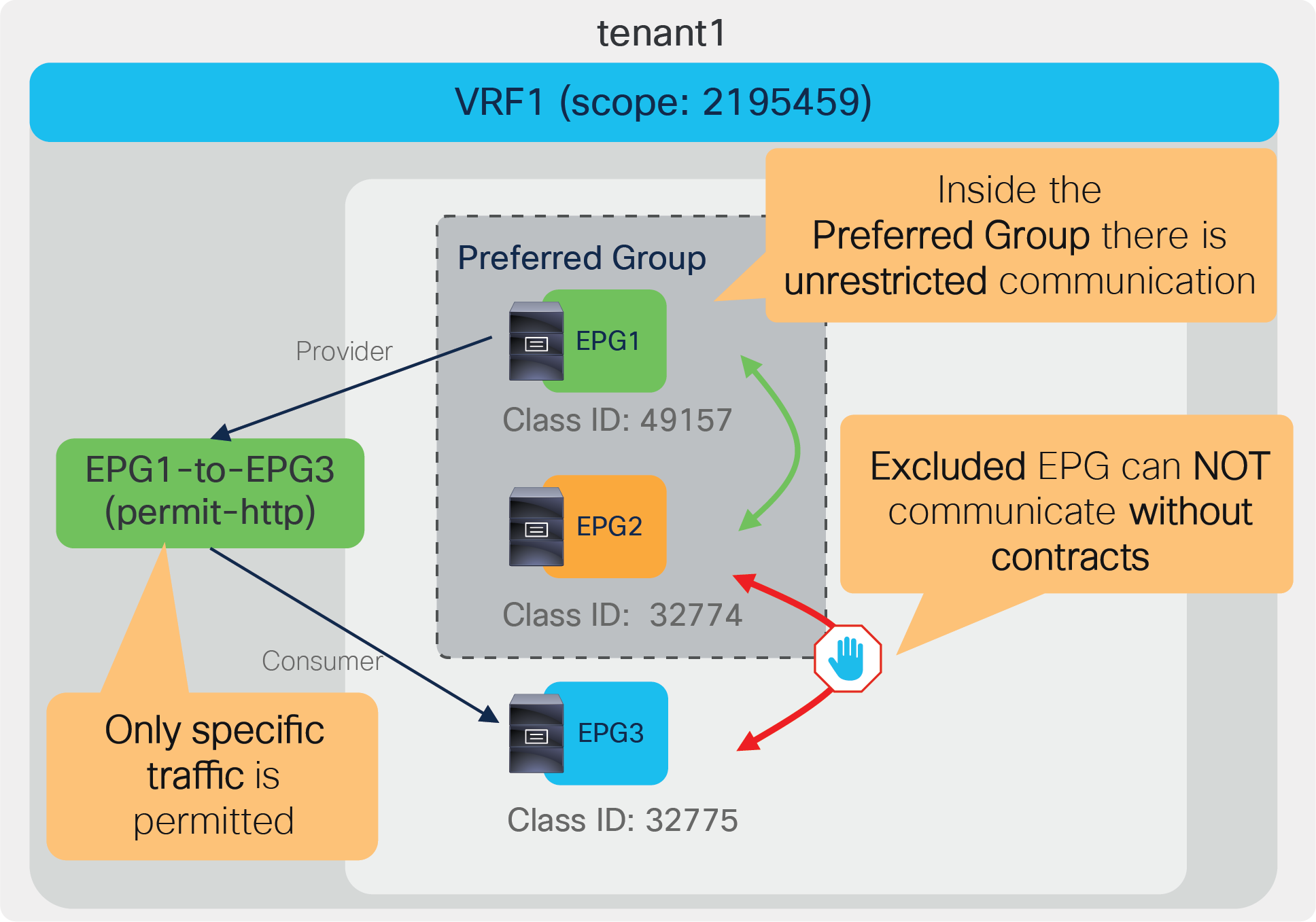
Exclude EPG3 from the preferred group and add a contract
The required configuration steps are as follows:
● Exclude EPG3 from the preferred group.
● Add a contract between EPG1 and EPG2.
Figures 168 and 169 summarize the required configurations.
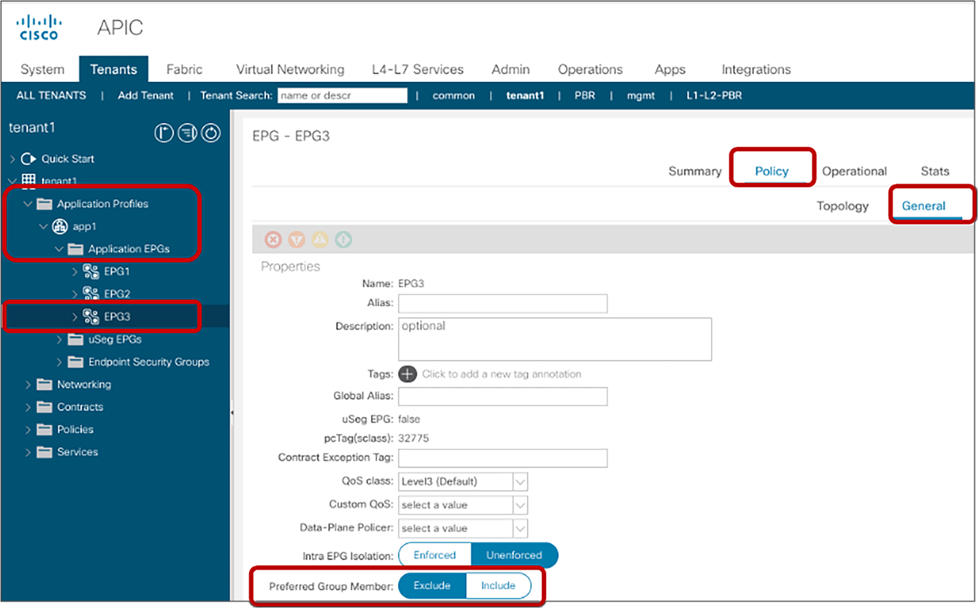
Exclude EPG3 from the preferred group
Once EPG3 is excluded from the preferred group, the zoning rules on tenant1 VRF1 are updated to deny traffic between EPG3 and other EPGs that are still in the preferred group. The “show zoning-rule” output of VRF1 in tenant1 is as follows:
Pod1-Leaf1# show zoning-rule scope 2195459
+---------+--------+--------+----------+---------+---------+---------+------+----------+----------------------------+
| Rule ID | SrcEPG | DstEPG | FilterID | Dir | operSt | Scope | Name | Action | Priority |
+---------+--------+--------+----------+---------+---------+---------+------+----------+----------------------------+
| 4104 | 0 | 32771 | implicit | uni-dir | enabled | 2195459 | | permit | any_dest_any(16) |
| 4103 | 0 | 0 | implicit | uni-dir | enabled | 2195459 | | permit | grp_any_any_any_permit(20) |
| 4102 | 0 | 0 | implarp | uni-dir | enabled | 2195459 | | permit | any_any_filter(17) |
| 4119 | 0 | 15 | implicit | uni-dir | enabled | 2195459 | | deny,log | grp_any_dest_any_deny(19) |
| 4143 | 49153 | 0 | implicit | uni-dir | enabled | 2195459 | | deny,log | grp_src_any_any_deny(18) |
| 4117 | 0 | 32775 | implicit | uni-dir | enabled | 2195459 | | deny,log | grp_any_dest_any_deny(19) |
| 4118 | 32775 | 0 | implicit | uni-dir | enabled | 2195459 | | deny,log | grp_src_any_any_deny(18) |
+---------+--------+--------+----------+---------+---------+---------+------+----------+----------------------------+
The red-highlighted entries for Rule IDs 4117 and 4118 are created by excluding EPG3 from the preferred group, which have higher priorities than the any-to-any implicit permit rule (Rule ID 4103).

Add a contract between EPG1 and EPG3.
After the contract between EPG1 and EPG3 is configured, the zoning-rules are updated, which permits traffic between them. The “show zoning-rule” output of VRF1 in tenant1 is as follows:
Pod1-Leaf1# show zoning-rule scope 2195459
+---------+--------+--------+----------+----------------+---------+---------+----------------------+----------+----------------------------+
| Rule ID | SrcEPG | DstEPG | FilterID | Dir | operSt | Scope | Name | Action | Priority |
+---------+--------+--------+----------+----------------+---------+---------+----------------------+----------+----------------------------+
| 4104 | 0 | 32771 | implicit | uni-dir | enabled | 2195459 | | permit | any_dest_any(16) |
| 4103 | 0 | 0 | implicit | uni-dir | enabled | 2195459 | | permit | grp_any_any_any_permit(20) |
| 4102 | 0 | 0 | implarp | uni-dir | enabled | 2195459 | | permit | any_any_filter(17) |
| 4119 | 0 | 15 | implicit | uni-dir | enabled | 2195459 | | deny,log | grp_any_dest_any_deny(19) |
| 4143 | 49153 | 0 | implicit | uni-dir | enabled | 2195459 | | deny,log | grp_src_any_any_deny(18) |
| 4117 | 0 | 32775 | implicit | uni-dir | enabled | 2195459 | | deny,log | grp_any_dest_any_deny(19) |
| 4118 | 32775 | 0 | implicit | uni-dir | enabled | 2195459 | | deny,log | grp_src_any_any_deny(18) |
| 4140 | 32775 | 49157 | 9 | bi-dir | enabled | 2195459 | tenant1:EPG1-to-EPG3 | permit | fully_qual(7) |
| 4139 | 49157 | 32775 | 8 | uni-dir-ignore | enabled | 2195459 | tenant1:EPG1-to-EPG3 | permit | fully_qual(7) |
+---------+--------+--------+----------+----------------+---------+---------+----------------------+----------+----------------------------+
The red-highlighted entries for Rule IDs 4139 and 4140 are created by the contract between EPG1 and EPG3, which have higher priorities than implicit deny rules for EPG3 (Rule IDs 4117 and 4118).
Add more specific rules
Figure 170 illustrates the design and configuration in this step. EPG1 and EPG2 have a contract to deny TCP traffic between them whereas other traffic is still permitted. It means you can still use a traditional block-list model for EPGs in the preferred group. Though deny action is used in this section as an example, other actions such as redirect and copy can be used.

Add a contract between EPG1 and EPG2
The required configuration steps are as follows:
● Add a contract to deny traffic between EPG1 and EPG2.
Figures 171 summarizes the required configurations.

Add a contract between EPG1 and EPG2
After the contract between EPG1 and EP2 is configured, the zoning-rules are updated, which deny traffic between them. The “show zoning-rule” output of VRF1 in tenant1 is as follows:
Pod1-Leaf1# show zoning-rule scope 2195459
+---------+--------+--------+----------+----------------+---------+---------+----------------------+----------+----------------------------+
| Rule ID | SrcEPG | DstEPG | FilterID | Dir | operSt | Scope | Name | Action | Priority |
+---------+--------+--------+----------+----------------+---------+---------+----------------------+----------+----------------------------+
| 4104 | 0 | 32771 | implicit | uni-dir | enabled | 2195459 | | permit | any_dest_any(16) |
| 4103 | 0 | 0 | implicit | uni-dir | enabled | 2195459 | | permit | grp_any_any_any_permit(20) |
| 4102 | 0 | 0 | implarp | uni-dir | enabled | 2195459 | | permit | any_any_filter(17) |
| 4119 | 0 | 15 | implicit | uni-dir | enabled | 2195459 | | deny,log | grp_any_dest_any_deny(19) |
| 4143 | 49153 | 0 | implicit | uni-dir | enabled | 2195459 | | deny,log | grp_src_any_any_deny(18) |
| 4117 | 0 | 32775 | implicit | uni-dir | enabled | 2195459 | | deny,log | grp_any_dest_any_deny(19) |
| 4118 | 32775 | 0 | implicit | uni-dir | enabled | 2195459 | | deny,log | grp_src_any_any_deny(18) |
| 4140 | 32775 | 49157 | 9 | bi-dir | enabled | 2195459 | tenant1:EPG1-to-EPG3 | permit | fully_qual(7) |
| 4139 | 49157 | 32775 | 8 | uni-dir-ignore | enabled | 2195459 | tenant1:EPG1-to-EPG3 | permit | fully_qual(7) |
| 4146 | 32774 | 49157 | 14 | bi-dir | enabled | 2195459 | tenant1:EPG1-to-EPG2 | deny | fully_qual(7) |
| 4124 | 49157 | 32774 | 14 | uni-dir-ignore | enabled | 2195459 | tenant1:EPG1-to-EPG2 | deny | fully_qual(7) |
+---------+--------+--------+----------+----------------+---------+---------+----------------------+----------+----------------------------+
The red-highlighted entries for Rule IDs 4124, and 4146 are created by the contract between EPG1 and EPG2, which have higher priorities than the any-to-any implicit permit rule (Rule ID 4103).
In summary, you can still use the traditional block-list model for EPGs in preferred group and migrate them to an ACI allow-list model by excluding EPGs from the preferred group if you identify the security requirements: what traffic should be explicitly permitted.
This section explains Cisco ACI contract related troubleshooting. It does not cover ACI forwarding related troubleshooting, such as routing and endpoint learning. For ACI troubleshooting including forwarding, please see the Cisco ACI troubleshooting guide for details: https://www.cisco.com/c/dam/en/us/td/docs/switches/datacenter/aci/apic/sw/4-x/troubleshooting/Cisco_TroubleshootingApplicationCentricInfrastructureSecondEdition.pdf
The following list describes the typical troubleshooting steps for contracts. The first step consists in troubleshooting routing, bridging, and endpoint learning as described in the ACI troubleshooting guide.
Some troubleshooting can be performed directly from the Cisco APIC GUI, because APIC aggregates the information from the entire fabric (for instance, when using the “log” option, you can view the information at the Tenant level). Other troubleshooting steps require connecting to individual leaf nodes (for instance, using the “show zoning-rule” command).
This section explains the steps specific to contracts (see steps 2 and 3 in the following list).
Typical troubleshooting steps for contracts:
1. Check the status of routing, bridging, and endpoint learning.
● Source and destination endpoints are learned if they are in EPGs connected to the ACI fabric.
● External routes are learned if the consumer or provider EPG is L3Out EPG.
2. Check that policies are programmed on the leaf nodes.
● Look up the EPG class IDs and VRF scope from the GUI.
● Understand on which leaf the policy should be programmed so you can perform per-leaf troubleshooting steps.
● Check the zoning rules on the consumer and provider leaf nodes.
3. Check the forwarding path for incoming traffic.
● Check the hit counters of the zoning rules on the individual leaf nodes.
● Check the deny logs and/or the add log to specific filtering rules, and check the permit logs, depending on the expected action. This step can be performed at the Tenant level on the GUI.
● Check the EPG classification for the traffic to confirm that the traffic arrives on the leaf, and that the expected policy is enforced.
● Capture the traffic on the destination to confirm that the traffic arrives at the destination.
4. Check the forwarding path for return traffic.
● Same as step 3 but for return traffic.
Check which policies are programmed on the leaf nodes
Look up the EPG class IDs and VRF scope
EPG class IDs and VRF scope are required to understand which policies are programmed on leaf nodes. These policies are also referred to as “zoning rules.” EPG class ID and VRF scope can be found at Tenant > Operational > Resource IDs.

Look up the EPG class ID and VRF scope
Understand where the policy should be programmed
Cisco ACI programs contract policies on either consumer or provider leaf nodes, not on spine nodes. In order to troubleshoot ACI filtering policies, you need to know on which leaf nodes they are programmed. Which consumer or provider leaf applies the policy is based on several different variables. Please refer to the table (Table 3) in the section “Traffic flow description with policy enforcement: ‘ingress’ and ‘egress’ enforcement.” to find out which leaf should have the expected zoning rules related to the contract, and enforces policy. The commands explained in the following subsections should be issued on that leaf.
show zoning-rule
The “show zoning-rule” command is a leaf-node-level command showing all of the zoning rules that are in place on a given leaf. By adding the option “scope VRF_scope,” shows the zoning rules at the VRF. This is useful to verify if the leaf node has the expected zoning rules and priorities.
Pod1-Leaf1# show zoning-rule scope 2850817
+---------+--------+--------+----------+----------------+---------+---------+-------------------+----------+----------------------+
| Rule ID | SrcEPG | DstEPG | FilterID | Dir | operSt | Scope | Name | Action | Priority |
+---------+--------+--------+----------+----------------+---------+---------+-------------------+----------+----------------------+
| 4211 | 0 | 16386 | implicit | uni-dir | enabled | 2850817 | | permit | any_dest_any(16) |
| 4208 | 0 | 0 | implicit | uni-dir | enabled | 2850817 | | deny,log | any_any_any(21) |
| 4222 | 0 | 0 | implarp | uni-dir | enabled | 2850817 | | permit | any_any_filter(17) |
| 4221 | 0 | 15 | implicit | uni-dir | enabled | 2850817 | | deny,log | any_vrf_any_deny(22) |
| 4216 | 16390 | 32775 | 71 | uni-dir-ignore | enabled | 2850817 | tenant1:Contract1 | permit | fully_qual(7) |
| 4244 | 32775 | 16390 | 69 | bi-dir | enabled | 2850817 | tenant1:Contract1 | permit | fully_qual(7) |
+---------+--------+--------+----------+----------------+---------+---------+-------------------+----------+----------------------+
show zoning-filters
The “show zoning-filter” command is a leaf-node-level command showing information about the filters used in the zoning rules. By adding “filter filter_ID,” the command shows information about the specific filter only.
Pod1-Leaf1# show zoning-filter filter 69
+----------+------+--------+-------------+------+-------------+----------+-------------+-------------+-----------+---------+-------+-------------+-------------+----------+
| FilterId | Name | EtherT | ArpOpc | Prot | ApplyToFrag | Stateful | SFromPort | SToPort | DFromPort | DToPort | Prio | Icmpv4T | Icmpv6T | TcpRules |
+----------+------+--------+-------------+------+-------------+----------+-------------+-------------+-----------+---------+-------+-------------+-------------+----------+
| 69 | 69_0 | ip | unspecified | tcp | no | no | unspecified | unspecified | 22 | 22 | dport | unspecified | unspecified | |
+----------+------+--------+-------------+------+-------------+----------+-------------+-------------+-----------+---------+-------+-------------+-------------+----------+
Pod1-Leaf1# show zoning-filter filter 71
+----------+------+--------+-------------+------+-------------+----------+-----------+---------+-------------+-------------+-------+-------------+-------------+----------+
| FilterId | Name | EtherT | ArpOpc | Prot | ApplyToFrag | Stateful | SFromPort | SToPort | DFromPort | DToPort | Prio | Icmpv4T | Icmpv6T | TcpRules |
+----------+------+--------+-------------+------+-------------+----------+-----------+---------+-------------+-------------+-------+-------------+-------------+----------+
| 71 | 71_0 | ip | unspecified | tcp | no | no | 22 | 22 | unspecified | unspecified | sport | unspecified | unspecified | |
+----------+------+--------+-------------+------+-------------+----------+-----------+---------+-------------+-------------+-------+-------------+-------------+----------+
Contract_parser
The contract_parser.py script helps parsing the zoning rules and matching them with EPG or contract names or L4 ports. As an example, it also displays the hardware statistics for the amount of traffic hitting a policy-cam rule.
Pod1-Leaf1# contract_parser.py -h
usage: contract_parser.py [-h] [--offline OFFLINE] [--offlineHelp] [--noNames]
[--noContract] [--noGraph] [--cache CACHE]
[--debug {debug,info,warning,error,critical}] [--nz]
[--incremented] [--node NODES [NODES...]]
[--contract CONTRACT [CONTRACT...]]
[--vrf VRF [VRF...]] [--epg EPG [EPG...]]
[--sepg SEPG [SEPG...]] [--depg DEPG [DEPG...]]
[--protocol PROT [PROT...]]
[--port PORT [PORT...]] [--sport SPORT [SPORT...]]
[--dport DPORT [DPORT...]] [--checkMask]
This script checks zoning rules, filters, and statistics and correlates with
EPG names. The results are printed in NXOS/IOS-like ACL syntax.
The following CLI output shows an example of the use of this script
Pod1-Leaf1# contract_parser.py --vrf tenant1:VRF1
Key:
[prio:RuleId] [vrf:{str}] action protocol src-epg [src-l4] dst-epg [dst-l4] [flags][contract:{str}] [hit=count]
[7:4281] [vrf:tenant1:VRF1] permit ip icmp tn-tenant1/ap-app1/epg-App(16389) tn-tenant1/ap-app1/epg-Web(32775) [contract:uni/tn-tenant1/brc-Contract1] [hit=0]
[7:4260] [vrf:tenant1:VRF1] permit ip tcp tn-tenant1/ap-app1/epg-App(16389) eq 22 tn-tenant1/ap-app1/epg-Web(32775) [contract:uni/tn-tenant1/brc-Contract1] [hit=0]
[7:4218] [vrf:tenant1:VRF1] permit ip icmp tn-tenant1/ap-app1/epg-Web(32775) tn-tenant1/ap-app1/epg-App(16389) [contract:uni/tn-tenant1/brc-Contract1] [hit=0]
[7:4253] [vrf:tenant1:VRF1] permit ip tcp tn-tenant1/ap-app1/epg-Web(32775) tn-tenant1/ap-app1/epg-App(16389) eq 22 [contract:uni/tn-tenant1/brc-Contract1] [hit=0]
[16:4257] [vrf:tenant1:VRF1] permit any epg:any tn-tenant1/bd-BD1(32772) [contract:implicit] [hit=0]
[16:4277] [vrf:tenant1:VRF1] permit any epg:any tn-tenant1/bd-BD2(32776) [contract:implicit] [hit=0]
[16:4259] [vrf:tenant1:VRF1] permit arp epg:any epg:any [contract:implicit] [hit=0]
[21:4220] [vrf:tenant1:VRF1] deny,log any epg:any epg:any [contract:implicit] [hit=0]
[22:4210] [vrf:tenant1:VRF1] deny,log any epg:any pfx-0.0.0.0/0(15) [contract:implicit] [hit=0]
Using the object store browser to find EPGs using a specific class-ID
Another tool that you can use for troubleshooting is the object store browser, which can be accessed at https://APIC_IP/visore.html. As an example, you may want to find which EPG is using a specific class ID. Figure 173 shows how to perform that search. This example is to search an EPG with class ID 16388. The class “fvAEPg” is the class name for EPG. The property “pcTag” means class ID.

Look up the EPG class ID and VRF scope
Checking whether traffic is hitting policy-cam rules
If zoning rules are programmed as expected, the next step is to verify if traffic hits the expected zoning rules.
This can be done in multiple ways:
● Using CLI commands per-leaf:
◦ View the hardware counters from the output of “show system internal policy-mgr stats” or from the output of “contract_parser,py”.
◦ Use the log capability.
● Using the APIC GUI:
◦ Use the log capability and viewing the per-packet log or the log statistics (in flow view) for the tenant (This was already covered in the section “Log”).
◦ Go to Tenant > Application Profile > EPG under the tab Operational > Contract and view the EPG-to-EPG traffic counters and associated contracts
◦ Use the fabric inventory view of the rules programmed on individual leaf nodes and view the statistics for the individual rules.
◦ Use the contract viewer application to view the aggregate traffic between EPG pairs.
show system internal policy-mgr stats
Cisco ACI hardware provides exact counters for each policy-cam rule that is programmed, with the exception of compressed rules.
The “show system internal policy-mgr stats” command is a leaf-node-level command that displays these hardware counters so the administrator can see the number of hits per zoning rule. This is useful to determine whether an expected rule is being hit.
Pod1-Leaf1# show system internal policy-mgr stats | grep 2850817
Rule (4208) DN (sys/actrl/scope-2850817/rule-2850817-s-any-d-any-f-implicit) Ingress: 0, Egress: 0, Pkts: 0 RevPkts: 0
Rule (4211) DN (sys/actrl/scope-2850817/rule-2850817-s-any-d-16386-f-implicit) Ingress: 0, Egress: 0, Pkts: 196 RevPkts: 0
Rule (4216) DN (sys/actrl/scope-2850817/rule-2850817-s-16390-d-32775-f-71) Ingress: 0, Egress: 0, Pkts: 0 RevPkts: 0
Rule (4221) DN (sys/actrl/scope-2850817/rule-2850817-s-any-d-15-f-implicit) Ingress: 0, Egress: 0, Pkts: 0 RevPkts: 0
Rule (4222) DN (sys/actrl/scope-2850817/rule-2850817-s-any-d-any-f-implarp) Ingress: 0, Egress: 0, Pkts: 0 RevPkts: 0
Rule (4244) DN (sys/actrl/scope-2850817/rule-2850817-s-32775-d-16390-f-69) Ingress: 0, Egress: 0, Pkts: 0 RevPkts: 0
<snip>
show logging ip access-list internal packet-log deny/permit
The “show logging ip access-list internal packet-log deny” command is a leaf-node iBash-level command to verify contract-related dropped information. This is useful to determine what traffic is being dropped by a contract. (Deny log is enabled by default).
Pod1-Leaf1# vsh -c 'show logging ip access-list internal packet-log deny' '| grep 2850817'
[2020-04-23T17:09:06.870966000+00:00]: CName: tenant1:VRF1(VXLAN: 2850817), VlanType: FD_VLAN, Vlan-Id: 89, SMac: 0x005056af31d3, DMac:0x0022bdf819ff, SIP: 192.168.1.1, DIP: 192.168.2.1, SPort: 37702, DPort
: 80, Src Intf: port-channel1, Proto: 6, PktLen: 74
[2020-04-23T17:09:01.317441000+00:00]: CName: tenant1:VRF1(VXLAN: 2850817), VlanType: FD_VLAN, Vlan-Id: 102, SMac: 0x005056af3f3b, DMac:0x0022bdf819ff, SIP: 192.168.2.1, DIP: 192.168.1.1, SPort: 49220, DPor
t: 22, Src Intf: port-channel2, Proto: 6, PktLen: 74
[2020-04-23T17:08:34.805576000+00:00]: CName: tenant1:VRF1(VXLAN: 2850817), VlanType: FD_VLAN, Vlan-Id: 89, SMac: 0x005056af31d3, DMac:0x0022bdf819ff, SIP: 192.168.1.1, DIP: 192.168.2.1, SPort: 37702, DPort
: 80, Src Intf: port-channel1, Proto: 6, PktLen: 74
<snip>
If traffic seems permitted unexpectedly, the “show logging ip access-list internal packet-log permit” command can be used to verify contract-related permit information. (Permit log is disabled by default).
Pod1-Leaf1# vsh -c 'show logging ip access-list internal packet-log permit' '| grep 2850817'
[2020-04-23T17:06:47.053769000+00:00]: CName: tenant1:VRF1(VXLAN: 2850817), VlanType: FD_VLAN, Vlan-Id: 89, SMac: 0x005056af31d3, DMac:0x0022bdf819ff, SIP: 192.168.1.1, DIP: 192.168.2.1, SPort: 52878, DPort: 22, Src Intf: port-channel1, Proto: 6, PktLen: 66
[2020-04-23T17:06:47.049224000+00:00]: CName: tenant1:VRF1(VXLAN: 2850817), VlanType: FD_VLAN, Vlan-Id: 89, SMac: 0x005056af31d3, DMac:0x0022bdf819ff, SIP: 192.168.1.1, DIP: 192.168.2.1, SPort: 52878, DPort: 22, Src Intf: port-channel1, Proto: 6, PktLen: 66
[2020-04-23T17:06:46.316771000+00:00]: CName: tenant1:VRF1(VXLAN: 2850817), VlanType: FD_VLAN, Vlan-Id: 89, SMac: 0x005056af31d3, DMac:0x0022bdf819ff, SIP: 192.168.1.1, DIP: 192.168.2.1, SPort: 52878, DPort: 22, Src Intf: port-channel1, Proto: 6, PktLen: 66
[2020-04-23T17:06:46.273541000+00:00]: CName: tenant1:VRF1(VXLAN: 2850817), VlanType: FD_VLAN, Vlan-Id: 89, SMac: 0x005056af31d3, DMac:0x0022bdf819ff, SIP: 192.168.1.1, DIP: 192.168.2.1, SPort: 52878, DPort: 22, Src Intf: port-channel1, Proto: 6, PktLen: 110
<snip>
The commands above are for per-packet information. Per-flow information can be verified by using the “show logging ip access-list cache deny” and “show logging ip access-list cache permit” commands on a leaf node. Deny- and permit-log information is available on the APIC GUI as well. Please refer to the section “Log” for more details.
Viewing contract rules statistics from the APIC GUI
In the APIC GUI, you can also troubleshoot ACI contracts and rules in certain cases at the Tenant level (with an aggregate view of the statistics from all leaf nodes) or from the Fabric Inventory view (which is the GUI equivalent of the per-leaf CLI commands).
Adding the log option to contract filter rules enables troubleshooting at the Tenant level, but it requires adding the log configuration to policy-cam rules and logging packets to the CPU: this requires extra configurations, and does not provide accurate counters (please see the section “Log” for details).
ACI also lets you see the aggregate information for the traffic going between EPGs and allowed by a given contract, as you can see in Figure 174. In order to view these statistics, you need to go to Tenant > Application Network Profile > EPG. Select the EPG, then look at the tab: Operational > Contracts > To EPG Traffic. This displays, for instance, the SSH traffic between the Web EPG and App EPG, whose respective 15-minute packet counters indicate 66 and 51. These are aggregate counters across all leaf nodes and do not offer a per-filter rule view.

EPG-to-EPG traffic statistics from the Tenant view
ACI also offers hardware counters for the policy-cam rules. You can view the statistics of each policy-cam rule from Fabric > Inventory > Pod > Leaf > Rules. You have to select the correct rule based on the VRF VNID (VRF scope ID) and the EPG pcTags (EPG class ID); you then get a view at the Stats Tab like the screenshot in Figure 175.

EPG-to-EPG traffic statistics from the Tenant view
One important observation is that the statistics for the policy-cam rules that can be viewed in the GUI depend on the monitoring-policy configuration. By default, the 15-minute statistics for the policy-cam rules are not enabled; this is considered a best practice because, at a large scale, the amount of statistics that ACI would have to collect otherwise could exceed the capacity of the APIC cluster database. It is therefore not recommended to modify the default. Just for your information, the monitoring-policy configuration for statistics related to the policy-cam rules is defined per-tenant (or, if you want to define it globally, it is defined in the common tenant).
You can find the configuration of the monitoring policy at Tenant > Policies > Monitoring. Under Monitoring in the common tenant, you would find the default policy, and in the default policy, the Stats Collection Policy. The object actrl.Rule defines how often the statistics are collected from the leaf nodes, as you can see in Figure 176.

Monitoring-policy configuration for policy-cam rules
Contract Viewer App
Another tool that helps troubleshooting EPG-to-EPG contracts and traffic forwarding is the “Contract Viewer App,” which can be downloaded from the Cisco DC App Center (https://dcappcenter.cisco.com). This application helps to visualize which portion of the tenant traffic is related to which EPG, and which portion of a given EPG traffic goes to which other EPG(s) and through which contract(s). If you installed the “Contract Viewer App,” it appears as a tab when selecting the tenant, as illustrated in Figure 177.

Contract Viewer to troubleshoot EPG-to-EPG traffic forwarding
What the figure illustrates is that EPGA-VRF is forwarding 51 percent of the traffic that is flowing through the tenant. If you highlight EPGA-VRF1, the application shows that the 100 percent of the traffic from EPGA-VRF1 goes to EPGD-VRF1, and filtering is performed by the filter rules of the contract “allow-ip-any-any.”
Checking the EPG classification for the traffic
If traffic doesn’t hit the expected zoning rules on the leaf, the next step is to verify that the EPG classification for the traffic is working as expected.
ELAM (Embedded Logic Analyzer Module)
ELAM provides an ASIC-level report used to check forwarding details such as the EPG classification information of the traffic and the drop reason if the traffic is dropped. This is useful to verify that traffic arrives on the leaf and that the source/destination class ID derivation is working as expected.
The details of how to use ELAM are not discussed in this document. Please refer to the “Intra-Fabric Forwarding” section in the Cisco ACI troubleshooting guide for more details: https://www.cisco.com/c/dam/en/us/td/docs/switches/datacenter/aci/apic/sw/4-x/troubleshooting/Cisco_TroubleshootingApplicationCentricInfrastructureSecondEdition.pdf
ELAM Assistant App
The ELAM Assistant App can be downloaded from the Cisco DC App Center (https://dcappcenter.cisco.com). This tool automates the deployment and interpretation of ELAMs through the GUI on the APIC.
Figure 178 shows an example of an ELAM matching a specific source and destination IPs on node-101 and node-102 downlink ports. In addition to the source and destination IPs, the source MAC, the destination MAC, and Class of Service (CoS) can also be added as matching parameters.

ELAM Assistant example (set ELAM)
By clicking on “Check Trigger,” an ELAM report is automatically generated if the packet was seen on a leaf as shown in Figure 179.
ELAM Assistant example (check report)
By clicking on “Report Ready,” the captured packet information output appears at the bottom of the work pane (see Figure 180). The report confirms that the packet was entered on eth1/6 and shows the packet information, such as the destination MAC, source MAC, VLAN, destination IP address, source IP address, protocol, L4 ports, etc.

ELAM Assistant example (check report)
The bottom of the report (as shown in Figure 181) shows the source and destination EPG classification information. It also shows the drop reason if the traffic was dropped. In this example, traffic from 192.168.1.1 in the Web EPG to 192.168.2.1 in the App EPG was dropped because there was no permit rule for the ICMP between them.

ELAM Assistant example (check EPG classification information and drop reason)
FAQ
This section covers frequently asked questions.
● System reserved: 1—15
● Global scope: 16—16384 for shared services provider EPGs
● Local scope: 16385—65535 for VRF scoped EPGs
Please refer to the section “Inter-VRF and inter-tenant contracts.”
● ARP reply (unicast)
● DHCP v4 (prot 0x11, sport 0x44, dport 0x43)
● DHCP v4 (prot 0x11, sport 0x43, dport 0x44)
● DHCP v6 (prot 0x11, sport 0x222, dport 0x223)
● OSPF (prot 0x59)
● EIGRP (prot 0x58)
● PIM (prot 0x67)
● IGMP (prot 0x2)
● ND-Sol ICMPv6 (prot 0x3a dport 0x0087)
● ND-Advt ICMPv6 (prot 0x3a dport 0x0088)
User-defined contract actions such as redirect, copy, and deny cannot be applied to the types of packets listed above with one exception: ARP reply (unicast).
Table 29 summarizes other implicit rules.
Table 29. Implicit rule list
| When it is used |
Source class ID |
Destination class ID |
Filter ID |
Action |
Explanation |
Priority* |
| 1 |
0 |
Implicit |
Permit |
This is to permit traffic from pervasive routes such as BD SVI and L3Out logical interface subnet to any. It does not appear in “show zoning-rule” output. |
0 |
|
| 0
10 |
10
0 |
Implicit (unspecified) |
Deny, log |
Deny traffic if for some reason traffic is incorrectly classified based on VLANs instead of MAC |
2 |
|
| Intra EPG permit |
EPG1 |
EPG1 |
Implicit (unspecified) |
Permit |
This is to permit intra-EPG communication. It is programmed in hardware during system startup on leaf nodes. It does appear not in "show zoning-rule” output. |
3 |
| 0 |
13 |
Implicit (unspecified) |
Deny |
This is to deny traffic to L3Out EPG subnets leaked from another VRF. This rule is programmed if the admin configures “Shared Route Control Subnet” without “Shared Security Import Subnet.” |
5 |
|
| Provider EPG Global class ID |
14 |
Implicit |
Permit |
The implicit rule is programmed in the provider VRF to permit traffic from the provider EPG to the consumer EPG. Then policy is enforced at the consumer VRF. |
9 |
|
| Provider EPG Global class ID |
0 |
Implicit (unspecified) |
Deny, log |
This is automatically added in the consumer VRF to deny traffic from the provider EPG to any EPG in the consumer VRF unless a contract is configured. |
12 |
|
| 0 |
BD class ID |
Implicit (unspecified) |
Permit |
Permit and flood the unknown unicast traffic on the ingress leaf and enforce the policy on the egress leaf. |
16 |
|
| 0 |
0 |
Implarp (EtherType: ARP) |
Permit |
Permit any-to-any ARP unicast traffic |
17 |
|
| 0 |
0 |
Implicit (unspecified) |
Deny, log |
Deny any-to-any traffic |
21 |
|
| 0 |
15 |
Implicit (unspecified) |
Deny, log |
It is not used and not even programmed on hardware unless preferred group is enabled. |
22 |
Table 30. Contract-, contract-subject-, and filter-related options available in MSO
| Location on MSO |
Cisco ACI Multi-Site Orchestrator (MSO) release when first introduced |
Note |
|
| Unenforced mode at VRF |
At VRF (read only) |
3.1(1) |
New VRFs created through MSO are set to enforced mode. If an existing VRF with unenforced mode is imported as a nonstretched VRF into MSO, MSO keeps the existing unenforced setting. |
| Preferred group at VRF Preferred group at EPG |
At EPG |
2.1(1) |
If at least one EPG is in a preferred group, the preferred group is automatically enabled at the VRF. |
| vzAny at VRF |
At VRF |
2.2(3) |
vzAny with Service Graph PBR is not supported. |
| Scope at contract |
At contract |
1.0 |
|
| Apply Both Directions at contract subject |
At contract |
1.0 |
Reverse Filter Port option is not available at MSO. It is always enabled if Apply Both Directions is enabled. |
| Service graph at contract subject |
At contract |
1.2(1) |
A two-node service graph requires MSO Release 2.0(1) or later. |
| QoS class at contract |
At contract |
3.1(1) |
|
| Target DSCP at contract |
Not available |
Roadmap 4.0 |
The setting can be managed at APIC level. MSO does not change the existing configuration. |
| WAN SLA policy at contract subject |
Not available |
Roadmap 4.0 |
The setting can be managed at APIC level. MSO does not change the existing configuration. |
| Enable Policy Compression at filter in a contract subject |
At filter chain in a contract |
2.2.(3) |
|
| Deny action at filter in a contract subject |
At filter chain in a contract |
3.1(1) |
|
This section covers advanced use cases. Please note that this section is for advanced readers.
L3Out EPG with 0.0.0.0/0 for inter-VRF contract
This sub-section explains the reason of the following consideration explained in L3Out EPG with 0.0.0.0/0 subnet.
● It’s recommended not to use an L3Out EPG with 0.0.0.0/0 subnet as the provider along with multiple consumer EPGs in other VRFs, because it potentially allows traffic between the consumer EPGs even if there is no contract between the consumer EPGs.
Figure 182 illustrates a configuration example that is NOT recommended. The provider VRF3 has an L3Out-EPG1 with 0.0.0.0/0 subnet that is the provider for the inter-VRF contract with the consumer EPGs: EPG1 in VRF1 and EPG2 in VRF2, which is intended to allow traffic from internal endpoints in EPG1 and EPG2 to the shared external network in VRF3. The zoning-rules will potentially allow traffic between endpoints in EPG1 and EPG2 even though there is no contract between EPG1 and EPG2.

Configuration example that is NOT recommended using an L3Out EPG with 0.0.0.0/0 subnet
Figure 183 and 184 illustrate traffic flow examples.
Traffic from 192.168.1.1 in VRF1 to 192.168.2.1 is permitted because VRF1 has 0.0.0.0/0 route and 32779-to-15 permit zoning-rule. If the ingress leaf doesn’t have the L3Out-EPG1 in VRF3 locally, the traffic is forwarded to the egress leaf via a spine. The egress leaf (VRF3) has a route to 192.168.2.0/24 that is leaked from VRF2, which is via a spine and it drops the traffic because of the ACL that prevents traffic sent back to a spine if the traffic comes from a spine (the only exception to this rule is when traffic hits a bounce entry). You can see this in Figure 183.

Traffic flow example: traffic between endpoints in VRF1 and VRF2 is denied
If the ingress leaf has the L3Out-EPG1 in VRF3 locally, the traffic is forwarded directly based on the VRF3 routing table, which results in the external router receiving the traffic as illustrated in figure 184. As the design is intended to allow traffic from internal endpoints in EPG1 and EPG2 to the shared external network in VRF3, it’s most likely that the external router has the route to the internal subnet and sends traffic back to the ACI border leaf. The border leaf receives the traffic from the external router, and the traffic is forwarded because VRF3 has 192.168.2.0/24 route and 5476-to-14 permit rule. The reason why the source class ID is 5476 here is because the source IP 192.168.1.1 is in the leaked subnet 192.168.1.0/24 that is classified to the VRF class ID. (If the consumer subnet leaked to the provider VRF is the destination, the destination class ID is 14 whereas the source class ID is the VRF class ID if the consumer subnet leaked to the provider VRF is the source).

Traffic flow example: traffic between endpoints in VRF1 and VRF2 is permitted
After the border leaf (VRF3) permits the traffic from the external router, traffic will be forwarded to the destination leaf where 192.168.2.1 is connected and the traffic is permitted because VRF2 has 5476-to-49156 permit zoning-rule. Such traffic flow might not be intended because traffic between endpoints in EPG1 and EPG2 is permitted even though there is no contract between EPG1 and EPG2.
If a specific subnets such as 0.0.0.0/1 and 128.0.0.0/1 instead of 0.0.0/0 are used for L3Out-EPG1, such traffic is not permitted. Figure 185 illustrates a configuration example. Instead of the VRF class ID (5476) and 15, the L3Out-EPG1 class ID (5475) is used in zoning-rules.

Configuration example using an L3Out EPG with specific subnets instead of 0.0.0.0/0
As illustrated in Figure 186, even if the ingress leaf has the L3Out-EPG1 in VRF3 locally and the border leaf receives the traffic from the external router, the border leaf (VRF3) drops the traffic because VRF3 doesn’t have 5476-to-14 permit rule.

Traffic flow example: traffic between endpoints in EPG1 and EPG2 is denied
Inter-VRF contract with vzAny as the consumer
This sub-section explains the following known caveat and design consideration of inter-VRF contract with vzAny as the consumer. This consideration is applicable to any contract action type.
● Inter-VRF vzAny-to-ESG is broken if you use an ACI version between 5.3(2d) or 6.0.3, and 6.1(2). Please refer CSCwm75928 for a workaround.
● After ACI version 6.1(2), inter-VRF vzAny-to-ESG works but you would see more TCAM consumption because of the rule expansion. If TCAM scale is a concern, you may consolidate a set of EPGs to an ESG or enable policy compression if the contract action is permit. Starting from ACI version 6.1(4), policy table compression is applicable to redirect action as well. Please see the section “Scalability considerations.” for more details.
Prior to ACI version 5.3(2d) or 6.0(3), in the case of inter-VRF vzAny-to-EPG/ExtEPG contract where EPG/ExtEPG is the provider, "0-to-provider_EPG/ExtEPG" zoning-rule was wrongly programmed in the provider VRF in addition to "provider_EPG/ExtEPG-to-0" rule. After the fix of CSCwi01316, the provider VRF doesn't have "0-to-provider_EPG/ExtEPG" and "provider_EPG/ExtEPG-to-0" zoning-rule. Instead, individual zoning-rules are programmed in the provider VRF for each global consumer class ID for provider-to-consumer direction, which is called "rule expansion" in this document.
Thus, after the fix of CSCwi01316, inter-VRF vzAny-to-EPG/ExtEPG contract will create the following zoning-rules:
● Consumer VRF: 0-to-provider_EPG/ExtEPG and provider_EPG/ExtEPG-to-0 (both directions)
● Provider VRF: provider_EPG/ExtEPG-to-14. And also, provider_EPG/ExtEPG-to-consumer_EPG/ExtEPG if the consumer's class ID is the global one because of another contract. (Note: the consumer ExtEPG with a “Shared Security Import Subnet” for inter-VRF contract always uses a global class ID)

Inter-VRF vzAny-to-EPG/ExtEPG contract behavior after the fix of CSCwi01316
After the fix of CSCwi01316, inter-VRF vzAny-to-ESG contract where ESG is the provider became broken because the provider VRF doesn't have "0-to-provider_ESG" zoning-rule (CSCwm75928). Since inter-VRF vzAny-to-ESG contract is supposed to be enforced on the provider VRF instead of the consumer VRF and the issue reported as CSCwi01316 needs to be avoided, the consumer-to-provider rule expansion in the provider VRF is implemented to fix the issue.
Thus, after the fix of CSCwm75928 (6.1(2) onward), inter-VRF vzAny-to-ESG contract will create the following zoning-rules:
● Consumer VRF: 0-to-14 implicit permit for the provider VRF enforcement.
Note that consumer VRF will still have 0-to-provider_ESG and provider_ESG-to-0 zoning-rules. 0-to-provider_ESG won’t be used for contract enforcement since the consumer VRF doesn’t apply the policy for consumer-to-provider direction whereas provider_ESG-to-0 could be used if the destination consumer endpoint is not known on the provider VRF.
● Provider VRF: individual zoning-rules for both directions. (That are consumer_ESG/ExtEPG-to-provider_ESG and provider_ESG-to-consumer_ESG/ExtEPG zoning-rules)
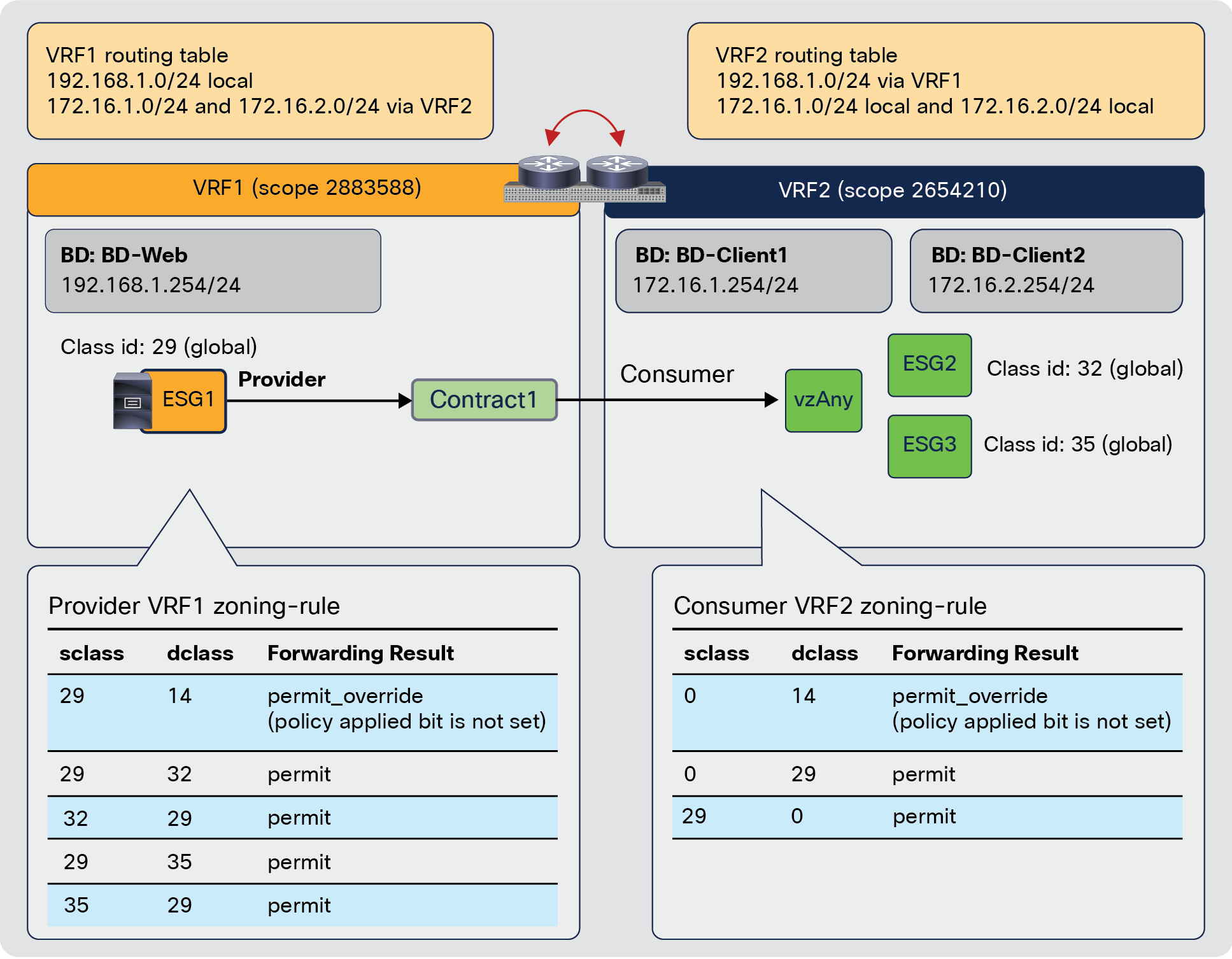
Inter-VRF vzAny-to-ESG contract behavior after the fix of CSCwm75928
Note: The individual zoning-rules in the provider VRF are not created for a service EPG/ESG. The figure below illustrates an example. 29-to-10933 rule doesn’t exist on the provider VRF whereas 10933-to-29 in the provider VRF and 10933-to-0 in consumer VRF exist to permit traffic after PBR. If you want to permit bi-directional traffic between consumer/provider and service EPG/ESG directly, you need another contract between them to add permit rule.

Service EPG/ESG is excluded from the rule expansion in the provider VRF
The behavior of inter-VRF vzAny-to-EPG/ExtEPG contract is same as the one prior to CSCwm75928.
Note: If the consumer VRF2 has an EPG or an external EPG that doesn't use a global class ID, rule expansion doesn't happen for inter-VRF communication. Even without the rule expansion, the inter-VRF communication may work depending on the provider ESG selector. If the provider ESG uses external EPG selector, external subnet selector or tags associated with external subnets, the provider ESG1 class ID can be always resolved in the consumer VRF. Then, the policy enforcement happens on the consumer VRF for both directions, which uses 0-to-29 and 29-to-0 rules in the consumer VRF. However, if the provider class ID cannot be resolved in the consumer VRF, the EPG or the external EPG in VRF2 cannot talk to ESG1 in VRF1 even though it's part of the vzAny in VRF2 because the rule expansion doesn’t happen for those EPGs. Thus, the recommendation is to migrate them to ESGs that always use global class IDs.
If you have another individual inter-VRF contract with a different action with the same provider and a consumer that is part of vzAny in the consumer VRF, please note that you could have conflicting rules in the provider VRF. The figure below illustrates an example. Although it’s an inter-VRF contract with vzAny, individual zoning-rules are created because of the rule expansion. As a result, you have the same zoning-rules for 29-to-35 and 35-to-29 that have different actions: redirect and permit.

Inter-VRF vzAny-to-ESG contract with redirect and another individual contract with permit
Thus, if you have such a configuration, ensure you use a more granular filter in the individual contract. The figure below illustrates an example where vzAny contract (Contract1) uses IP filter and the individual contract (Contract2) uses TCP filter. TCP traffic from an endpoint in ESG1 to a destination in ESG3 will be permitted because of 29-to-35 (TCP filter) permit rule in the provider VRF, which is more granular than 29-to-35 (IP filter) redirect rule. The return traffic will be also permitted because of 35-to-29 (TCP filter) permit rule in the consumer VRF, which is more granular than 0-to-29 (IP filter) redirect rule. Even if the destination class ID of the return traffic cannot be resolved in the consumer VRF, it hits 0-to-14 implicit permit rule in the consumer VRF and will hit 35-to-29 (TCP filter) permit rule in the provider VRF. If it’s UDP traffic between ESG1 and ESG3, or IP traffic between ESG1 and ESG2, it will be redirected for both directions.

The use of granular rule in the individual contract
Note for advanced readers: the reason why a more granular filter needs to be used in the individual contract instead of in the vzAny contract to avoid conflict is because the provider to consumer traffic could hit the rules created by vzAny contract instead of the rules created by the individual contract. The figure below illustrates an example where vzAny contract (Contract1) uses TCP filter and the individual contract (Contract2) uses IP filter. TCP traffic from an endpoint in ESG3 to a destination in ESG1 will be permitted because of 35-to-29 (IP filter) permit rule in the consumer VRF because it’s more granular than 0-to-29 (TCP filter) redirect rule. However, the return traffic will be redirected because of 29-to-35 (TCP filter) redirect rule in the provider VRF because it’s more granular than 29-to-35 (IP filter) permit rule, which causes asymmetric forwarding.
Why the use of granular rule in the vzAny contract doesn’t work
Table 31. Document history
| New or Revised Topic |
Described in |
Date |
| Added a design consideration for L3Out EPG with 0.0.0.0/0 subnet |
January 11, 2023 |
|
| Added a general recommendation for scale |
General recommendation to increase efficiency and simplify ACI contracts |
October 10, 2023 |
| Added Inter-VRF contract with vzAny as the consumer |
November 20, 2024 |
|
| Added policy table compression for redirect action in APIC release 6.1(4). |
December 8, 2025 |
|
| Added a consideration for inter-VRF contract with vzAny as the consumer |
February 6, 2026 |