Cisco ACI Multi-Site and Service Node Integration for ACI versions 6.1(3) or earlier White Paper
Available Languages
Bias-Free Language
The documentation set for this product strives to use bias-free language. For the purposes of this documentation set, bias-free is defined as language that does not imply discrimination based on age, disability, gender, racial identity, ethnic identity, sexual orientation, socioeconomic status, and intersectionality. Exceptions may be present in the documentation due to language that is hardcoded in the user interfaces of the product software, language used based on RFP documentation, or language that is used by a referenced third-party product. Learn more about how Cisco is using Inclusive Language.
This document describes the deployment considerations for integrating Layer-4 through Layer-7 (L4–L7) network services in a Cisco® Application Centric Infrastructure (Cisco ACI®) Multi-Site fabric. The document specifically focuses on stateful firewalls (FWs) and load balancers. The following use cases are considered:
● Layer-3 firewall design
● Layer-3 load-balancer design
● Layer-3 firewall and load-balancer service chain
● North-south and east-west service insertion design
● Independent clustered service nodes in each site
To best understand the design presented in this document, you should have basic knowledge of the Cisco ACI Multi-Site solution, the deployment of L3Out connectivity between the Multi-Site fabric and the external Layer-3 domain, and the functionality of service graphs with Policy-Based Redirect (PBR).
Starting from release 3.0(1) of the Cisco ACI software, Cisco offers the Cisco ACI Multi-Site solution, which allows you to interconnect multiple Cisco ACI sites, or fabrics, under the control of the different Cisco Application Policy Infrastructure Controller (APIC) clusters. This solution provides an operationally simple way to interconnect and manage different Cisco ACI fabrics that may be either physically collocated or geographically dispersed.
For more information about the Cisco Multi-Site architecture, please refer to the following white paper:
https://www.cisco.com/c/en/us/solutions/collateral/data-center-virtualization/application-centric-infrastructure/white-paper-c11-739609.html.
In this document, we use the terms “site” and “fabric’ interchangeably to refer to a single “APIC domain,” which could represent a single pod or a Cisco ACI Multi-Pod fabric deployment.
Cisco ACI offers the capability to insert L4–L7 services, such as firewalls, load balancers, and Intrusion Prevention Services (IPSs), using a feature called a service graph.
For more information, please refer to the Cisco ACI service-graph-design white paper:
https://www.cisco.com/c/en/us/solutions/collateral/data-center-virtualization/application-centric-infrastructure/white-paper-c11-2491213.html.
The service-graph functionality can then be enhanced by associating to it one or more Policy-Based Redirection (PBR) policies.
For more detailed information on Cisco ACI contracts and PBR, please refer to the Cisco ACI contract guide white paper and to the Cisco ACI PBR white paper:
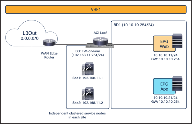
As of Cisco ACI Release 6.0(5), the recommended option for integrating L4–L7 services into a Cisco ACI Multi-Site architecture calls for the deployment of independent service nodes in each site (Figure 1).
This is the logical consequence of the fact that the ACI Multi-Site architecture has been designed to interconnect separate ACI fabrics, at both the network fault domain and management levels. The focus in this document, therefore, will be exclusively on this deployment model.
The service-node High Availability options considered in this paper are the following ones:
● Active/standby service-node pair in each site
● Active/active cluster in each site
● Independent active service nodes in each site
It is possible to mix and match each HA option in the different fabrics that are part of the Multi-Site domain:
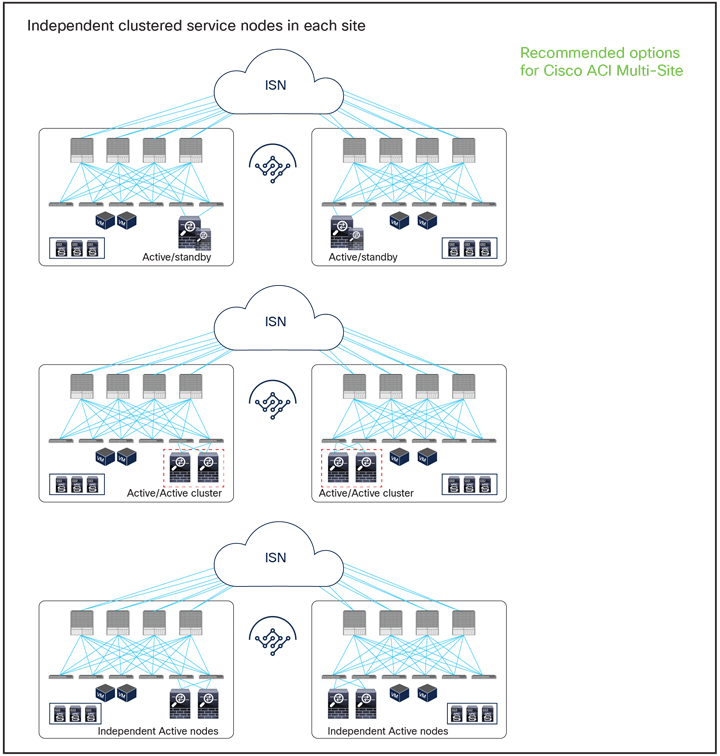
Recommended network services deployment options with the Cisco ACI Multi-Site solution
Note: This white paper uses an active/standby service-node pair in each site mainly in the figures, though the other HA options shown in Figure 1 are also supported.
This model mandates that symmetric traffic flows through the service nodes be maintained, because the connection state is not synchronized between independent service nodes deployed in different sites. This requirement can be achieved with the following approaches:
● Use of host-route advertisement for north-south communication with stateful firewall nodes connected through L3Out: this allows connecting independent firewall nodes deployed between the border leaf nodes and the external WAN edge routers because inbound traffic is always optimally steered toward the site where the destination endpoint resides, whereas outbound traffic usually goes back through the same local L3Out connection. This approach, while fully supported and useful in many cases, relies on a more traditional routing design and only applies to north-south communication; this document therefore focuses on the second approach, described below, which leverages the advanced service insertion capabilities offered by an ACI network infrastructure.
● Use of service graph with PBR for both north-south and east-west communication: you can deploy service graph with policy-based redirect (PBR) for both north-south and east-west security policy enforcement. This approach is the most flexible and recommended solution. It consists of defining a PBR policy in each site that specifies at least a local active service node but it is also possible to deploy multiple active service nodes in the same site by leveraging symmetric PBR. The Cisco Nexus® 9000 Series Switches, used as leaf nodes, would then apply the PBR policy, selecting one of the available service nodes for the two directions of each given traffic flow (based on hashing). Different deployment models are supported for the service nodes: L3-routed mode (which has been supported from the beginning) but also L1/L2 inline/transparent mode as well.
● Starting from ACI Release 6.0(4c), support for new PBR use cases has been added, allowing to associate a service graph (with redirection enabled) to vzAny or for intersite transit routing communication. More details about those new use cases will be found in later sections of this paper.
Figure 2 and Figure 3 illustrate the other two models for the deployment of clustered service nodes between sites.
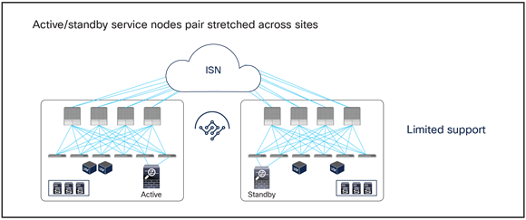
Limited support network services deployment options with the Cisco ACI Multi-Site solution
● Active/standby service nodes pair stretched across sites: this model can be applied to both north-south and east-west traffic flows. This fail-safe model does not allow the creation of an asymmetric traffic path that could lead to communication drops. At the same time, because of the existence of a single active service node connected to the Multi-Site fabric, this option has certain traffic-path inefficiencies, because by design some traffic flows will hair-pin across the Intersite Network (ISN). Therefore, you should be sure to properly dimension the bandwidth available across sites and consider the possible latency impact on application components connected to separate sites. Also, this approach is only supported if ACI only performs Layer-2 forwarding (firewall as the default gateway for the endpoints or firewall in transparent mode) or when the active/standby firewall pair is connected to the fabrics via L3Out connections.

Active-active service node cluster deployment options with the Cisco ACI Multi-Site solution
● Active/active clustered service nodes that use the same virtual MAC and virtual IP addresses stretched across sites: this model cannot be applied to a Multi-Site environment as of ACI Release 6.0(4c), though an active/active firewall cluster can be stretched across pods in a Cisco ACI Multi-Pod environment. In the Cisco firewall implementation, this deployment model takes the name of Split Spanned EtherChannel cluster: all the firewall nodes that are part of the same cluster are seen as a logical distributed firewall reachable through a single virtual MAC and virtual IP. ACI Multi-Site does not currently support the capability of discovering the same virtual MAC and virtual IP pair across different sites. This situation, where the same endpoint is continuously learned in different locations, is considered to be an endpoint flapping scenario.
● Active/active clustered service nodes that use unique MAC and IP addresses across sites: this represents a second implementation option of an active/active firewall clustering, where each firewall node that is part of the same cluster owns its unique MAC and IP addresses. This option, supported by Cisco firewalls and some third-party implementations, can work today with an ACI Multi-Site architecture for some use cases[1]. Although this option works, the deployment models illustrated in Figure 1 are still primarily recommended, because clustering across sites potentially consumes more firewall resources, and connection sync across firewalls in different sites is not really required when deploying Cisco ACI PBR functionalities. The Cisco ACI fabric forwarding behavior is the same as the one used for independent clustered service nodes in each site, which is explained as part of the “Multi-Site service graph with PBR use cases” section in this paper.
Note: Cisco ACI Multi-Pod remains the recommended architectural approach for the deployment of active/standby service-node pairs across data centers and active/active clustered service nodes with the same virtual IP and virtual MAC addresses across data centers.
For more information, Please refer to the following white paper:
https://www.cisco.com/c/en/us/solutions/collateral/data-center-virtualization/application-centric-infrastructure/white-paper-c11-739571.html.
Service node integration with Cisco ACI Multi-Site architecture
Design options and considerations
Several deployment models are available for integrating network services in a Cisco ACI Multi-Site architecture. To determine the best options to choose, you should consider all the specific requirements and characteristics of the design:
● Service-node insertion use case
◦ North-south service node (or perimeter service node), for controlling communications between the data center and the external Layer-3 network domain.
◦ East-west service node, for applying policies for traffic flows within the data center and across sites. For the east-west enforcement, there are two cases to consider: in the first one, the service node is used to apply policies between endpoint groups (EPGs) that are part of the same virtual routing and forwarding (VRF). The second scenario, very commonly deployed, is the one where a service node (or its virtual context) frontends each tenant/VRF, so as to be able to apply security policies to all of the inter-VRF traffic.
● Service-node appliance form factor
◦ Physical appliance
◦ Virtual appliance
● Service-node type
◦ Inline (Layer 1 [L1]), transparent (Layer 2 [L2]), or routed (Layer 3 [L3]) mode firewall/IPS with PBR
◦ Routed (Layer 3) mode load balancer with SNAT or without SNAT
● Service-node high-availability model
◦ Active/standby HA pair in each site
◦ Active/active cluster in each site
◦ Independent active nodes in each site
● Connectivity to the external Layer-3 network domain
◦ Traditional L3Outs deployed on the border leaf nodes
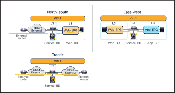
This document focuses on the service-node insertion use cases discussed below, describing traffic flows and associated deployment considerations for each option in detail:
● North-south (intra-VRF): traffic flows between the external Layer-3 network domain and the web endpoint group (EPG) part of the same VRF.
● East-west (intra-VRF): traffic flows between EPGs that are in the same VRF.
● East-west (inter-VRF): traffic flows between EPGs that are in different VRFs.
● Intersite transit routing (intra-VRF and inter-VRF): intersite traffic flows between external Layer-3 network domains that are in the same VRF or in different VRFs.
Note: All the use cases listed above will be discussed in the section “Multi-Site service graph with PBR use cases” which means that the internal endpoints or the L3Out connections with the external network domain can be either part of the same fabric or spread across different fabrics.
The figures below show the use cases covered in this document.
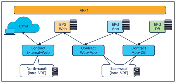
North-south and east-west service nodes (intra-VRF)
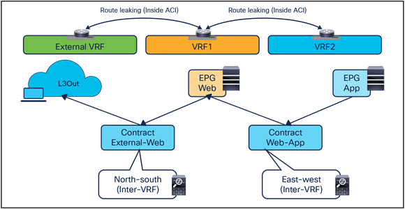
North-south and east-west service nodes (inter-VRF)
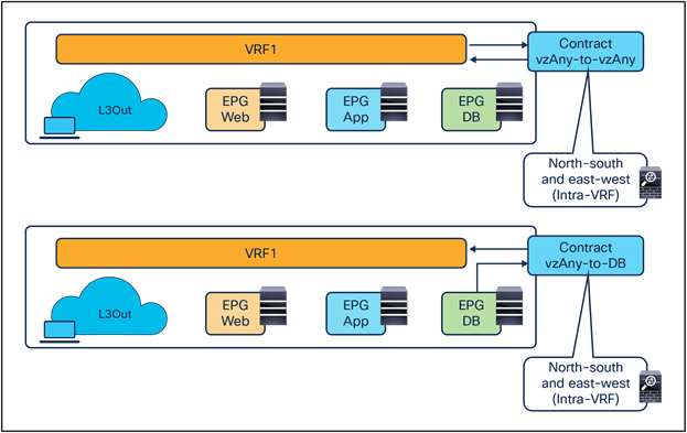
North-south and east-west service nodes with vzAny (intra-VRF)
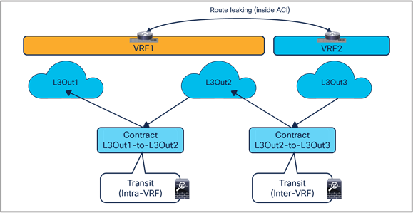
Transit service nodes (intra-VRF and inter-VRF)
Overview of the recommended design
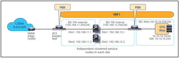
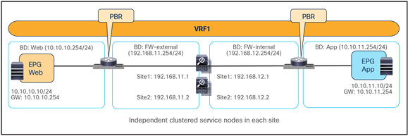
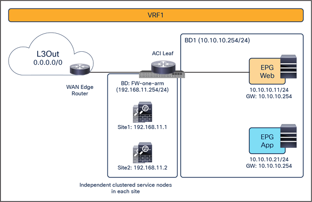
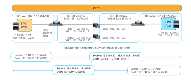
Figure 8 shows a high-level view of the topology representing the recommended deployment option with independent clustered service nodes in each site. We are going to use routed mode firewall, routed mode load balancer, and traditional L3Outs as examples in this document.
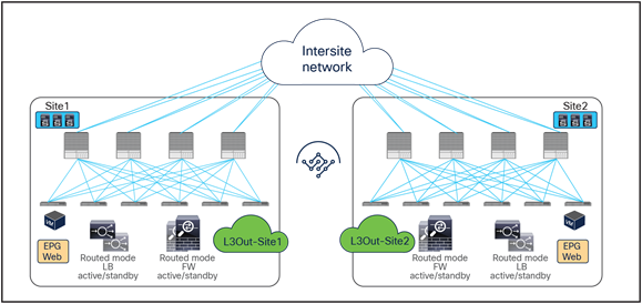
Independent clustered service nodes in each site
The deployment of independent service nodes across sites raises an operational concern about how to maintain policy configuration consistency across them. In the specific example of Cisco® firewalls, some options are available:
● Cisco Security Manager for Adaptive Security Appliances (ASAs):
For more information, see https://www.cisco.com/c/en/us/products/security/security-manager/index.html.
● Cisco Firepower® Management Center (FMC) for Cisco Firepower Next-Generation Firewall (NGFW) devices:
For more information, see https://www.cisco.com/c/en/us/products/security/firesight-management-center/index.html.
When planning for the deployment of this model, it is important to keep in mind a few important design requirements:
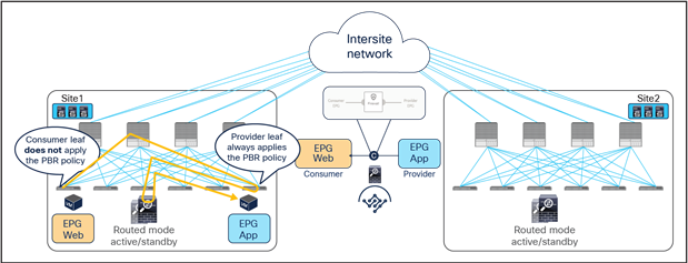
● The policy to be applied (the ‘intent”) is defined directly on Cisco Nexus Dashboard Orchestrator (NDO) and could, for example, specify that any communication between the external EPG (modeling the external Layer-3 network domain) and the internal Web EPG must be sent through a service node (or a chain of service nodes). Each specific service node is then mapped, at the site level, to the specific physical or virtual service appliances locally deployed.
● In the current implementation, the PBR policy applied on a leaf switch can only redirect traffic to a service node deployed in the local site. As a consequence, it becomes paramount to improve the resiliency of the local service nodes. This can be achieved with the different options shown in Figure 9.
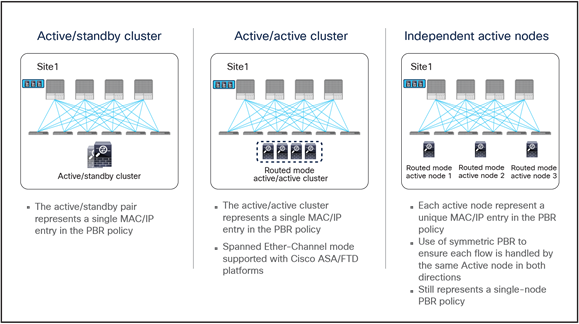
Deployment options to increase the resiliency of service nodes in a single site
The first two models are obvious, as they both ensure that the service node is seen by the fabric as a single entity, so the PBR policy would only contain a single MAC/IP pair. With the third option, multiple MAC/IP pairs are instead specified in the same PBR policy, so that a given traffic flow can be redirected to a service node. Use of symmetric PBR ensures that both the incoming and return directions of the same flow are steered through the same service node.
The definition and behavior of an active/active cluster differs depending on the vendors. In the case of Cisco ASA and a Cisco Firepower Threat Defense (FTD) active/active cluster, service nodes in the same cluster can use the same MAC and IP addresses, which is the second option in the figure above, whereas service nodes in the same Palo Alto Networks active/active HA use unique IPs, which is an enhanced version of the third option.
Note: Cisco ASA can also support an active/active cluster where each firewall node owns a unique MAC/IP address pair.
As previously mentioned, service graph with PBR can be used to handle service-node insertion for north-south, east-west, and transit traffic flows, as illustrated in Figure 10.
Service-node insertion for north-south, east-west, and transit traffic flows (one-arm example)
Several considerations apply when deploying service graph with PBR in an ACI Multi-Site architecture:
● Service graph with PBR integration with Multi-Site is only supported when the service node is deployed in unmanaged mode. This implies that ACI only takes care of steering the traffic through the service node; the configuration of the service node is, instead, not handled by the APIC. As such, there is no requirement to support any device package, and any service node (from Cisco or a third-party vendor) can be integrated with this approach.
● In the example in Figure 10, the service node is deployed in one-arm mode, leveraging a single interface to connect to a dedicated service Bridge Domain (BD) defined in the ACI fabric. It is worth being reminded that in order to leverage service graph with PBR with ACI Multi-Site, the service node must be connected to a BD and not to an L3Out logical connection, which essentially means that no dynamic routing protocol can be used between the service node and the ACI fabric. The deployment of one-arm mode is therefore advantageous, because it simplifies the routing configuration of the service node, which requires only the definition of a default route pointing to the service BD IP address as next-hop. That said, two-arm deployment models (with inside and outside interfaces connected to separate BDs) are also fully supported, as shown in Figure 11.
● The service BD(s) must be L2-stretched across sites. This means that the interfaces of the service nodes in different sites must be in the same service BD. The recommendation is to do this without extending BUM flooding, to avoid spreading broadcast storms outside a single fabric.
● For the north-south use case, the regular EPGs such as Web EPG and App EPG can be stretched across sites or locally confined in a site. As of Cisco ACI Release 6.0(5), the external EPG (L3Out EPG) can be a local object or a stretched object (that is, defined on the Cisco Nexus Dashboard Orchestrator as part of a template mapped to all the deployed sites), depending on the external connectivity design.
● For the east-west use case, the regular EPGs such as Web EPG and App EPG can be stretched across sites or locally confined in a site (or a combination of the two). For specific EPG-to-EPG contracts with PBR, an IP prefix must be configured under the consumer EPG, covering all the endpoints that are part of that EPG, which is easy to do if each EPG gets assigned to its own BD (and IP subnet) but may become more challenging if multiple EPGs are configured as part of the same BD (and IP subnet). Cisco ACI Release 6.0(3d) introduces support for the definition of /32 (IPv4) and /128 (IPv6) prefixes under the consumer EPG (this was not possible in previous releases because of CSCwa08796). While operationally complex, this approach offers a possible option for the deployment of east-west PBR in ACI “application-centric” Multi-Site deployments where multiple EPGs are configured as part of the same BD (and IP subnet).
● For east-west use case (EPG-to-EPG contract with PBR), features for specific IP endpoints or host prefixes (/32 for IPv4 and /128 for IPv6) such as static route on a bridge domain, Anycast MAC/IP and Microsoft NLB are not supported.
● Prior to Cisco ACI release 4.2(5) or 5.1(1), the north-south use case using an EPG-to-L3Out contract with PBR is supported only intra-VRF. The east-west use case can be supported either intra-VRF or inter-VRF (and inter-tenant). Support for the north-south inter-VRF (and inter-tenant) use case requires Cisco ACI release 4.2(5), 5.1(1), or later.
● vzAny PBR (vzAny-to-vzAny, vzAny-to-EPG, and vzAny-to-L3Out) and L3Out-to-L3Out PBR use cases require Cisco ACI Release 6.0(4c) or later, and Cisco Nexus Dashboard Orchestrator (NDO) Release 4.2(3e) or later. vzAny-to-vzAny, vzAny-to-L3Out, and L3Out-to-L3Out PBR must use one-arm service node instead of two-arm. For more guidelines and deployment considerations for those new cases, please refer to the section “Multi-Site service graph with PBR use cases.”
● Consumer endpoints of an east-west contract with PBR must not be connected under the border leaf node where an intersite L3Out resides.
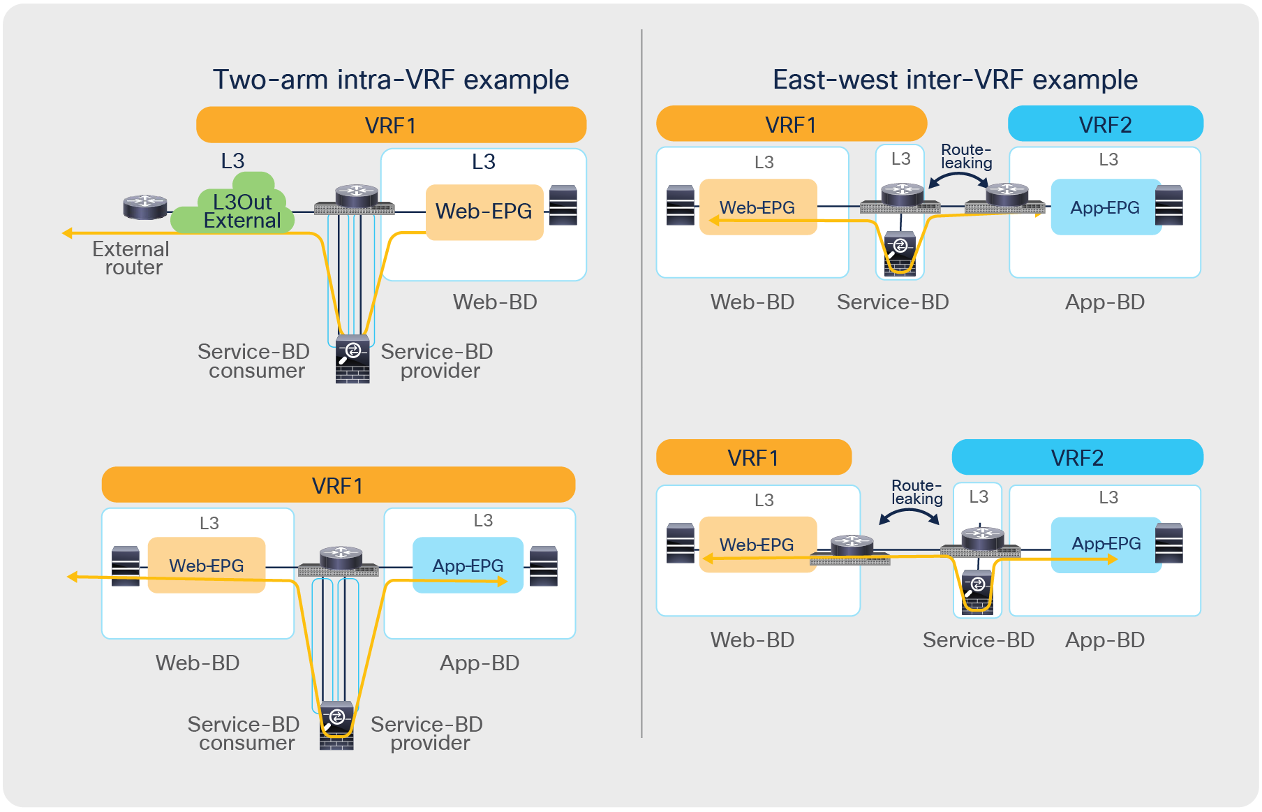
Other service-insertion examples (one-arm and two-arms examples)
Though this document uses mainly a two-arm mode design in its examples, both one-arm and two-arm are valid options, except for the vzAny PBR (vzAny-to-vzAny, vzAny-to-EPG, and vzAny-to-L3Out) and L3Out-to-L3Out PBR use cases, which mandate one-arm mode service nodes.
The following are general L3 PBR design considerations that are applied to PBR in Multi-Site as well:
● In a Multi-Site design, redirection to a PBR node is only supported to an interface that is connected to a bridge domain (that is, the interface cannot be connected to an L3Out). However, the same physical interface connecting a PBR node to the fabric could be used for both types of connectivity when leveraging different logical interfaces (each associated to a separate VLAN tag). For example:
◦ The PBR node is connected to Leaf1 Ethernet 1/1 and uses VLAN 10 to connect to the service bridge domain. This is the logical interface used for PBR for east-west communication between EPGs.
◦ The PBR node uses, instead, VLAN 20 on the same interface Ethernet 1/1 on Leaf1 to connect to an L3Out (the L3Out must use SVIs in that case). This is the logical interface that could be used for north-south traffic, using the service node as a perimeter firewall (FW).
● The PBR node interfaces can be part of the same bridge domain used by the consumer/provider EPG, or you can define different dedicated service bridge domains.
● The PBR node can be deployed in two-arm mode or in one-arm mode with a single interface connected to a service bridge domain. As already mentioned, this is not valid for the vzAny PBR and L3Out-to-L3Out use cases, which, as of Cisco ACI Release 6.0(5), still mandate the deployment of one-arm mode service nodes except vzAny-to-EPG use case that supports two-arm and multiple nodes starting from ACI Release 6.1(3).
● Prior to Cisco ACI Release 5.2(1), the deployment of an active/standby service node pair is only supported if the active device always uses the same virtual MAC (vMAC) address. This is because those older ACI releases do not support dynamic PBR destination MAC address detection, and traffic redirection is performed by statically configuring the MAC address associated to the active service-node Virtual IP (VIP). This requirement implies that when a service node failover occurs, the standby unit that is activated must inherit both the VIP and vMAC addresses of the failed active unit (this is, for example, the case with Cisco ASA and Cisco Firepower models). Depending on the service node vendor, this might not be the default behavior, but it might have the vMAC address as a configuration option. Starting from Cisco ACI Release 5.2, this consideration is no longer applicable if dynamic PBR destination MAC detection is used instead of static PBR destination MAC configuration.
While not the main focus of this document, the following are general L1/L2 PBR design considerations that are also applied to PBR in Multi-Site:
● Cisco ACI Release 4.1(1) or later is required.
● The PBR node interfaces must be part of dedicated bridge domains.
● The PBR node can be deployed in two-arm mode, not one-arm mode.
Note: The term “PBR node” refers to the network services node (firewall, load balancer, etc.) specified in the PBR policy.
In addition to this, the deployment of the vzAny PBR use cases (vzAny-to-vzAny, vzAny-to-EPG, and vzAny-to-L3Out) and the L3Out-to-L3Out PBR use case in an ACI Multi-Site architecture is subject to the following considerations:
● Cisco ACI Release 6.0(4c) or later is required.
● Cisco Nexus Dashboard Orchestrator Release 4.2(3e) or later is required.
● Single-node service graph is supported, not multiple-nodes service graph.
● Only one-arm mode is supported for the service device.
● Starting from ACI Release 6.1(3), vzAny-to-EPG use case supports two-arm and multiple nodes.
For more information about generic PBR design considerations and configurations, please refer to the document below:
https://www.cisco.com/c/en/us/solutions/data-center-virtualization/application-centric-infrastructure/white-paper-c11-739971.html.
Multi-Site service graph with PBR use cases
The following sections describe different use cases where service graph with PBR can be used to redirect north-south and east-west traffic flows to a service node (or to a chain of service nodes). The specific scenarios that will be considered are:
● The deployment of a single-node service graph, for redirecting traffic flows either to a firewall service or to a load-balancer service.
● The deployment of a multi-nodes service graph for redirecting traffic flows to a service chain built with firewall and load-balancer services.
As previously discussed in the “Recommended design overview” section, in an ACI Multi-Site architecture each specific type of service is implemented by leveraging a distributed model, with a separate set of service nodes in each fabric. For example, a firewall service can be represented by the deployment in each site of an active/standby pair of firewalls or of one of the other redundancy options previously shown in Figure 1. The same considerations apply to the deployment of a load-balancer service.
The critical requirement for integrating distributed stateful service nodes into an ACI Multi-Site architecture is avoiding the creation of asymmetric traffic paths for the incoming and return directions of flows, because doing so would cause communication drops due to the stateful nature of those service nodes. Figure 12 illustrates an example. For incoming traffic from an external client to an internal endpoint in site2, traffic may be steered toward the L3Out in site1, depending on the routing design. However, the outbound traffic from the internal endpoint goes out (by default) through the local L3Out in site2. The return traffic would, hence, be dropped by the external firewall connected to site2 since the firewall does not have the connection state information for the traffic flow that was created earlier on the external firewall connected to site1.
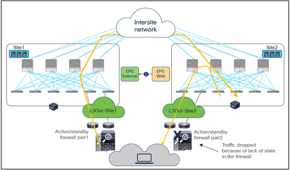
Why traffic symmetricity is important in multilocation data centers
Even if the external firewall connected to site2 has an Access Control List (ACL) to permit outgoing traffic, the external firewall connected to site2 will drop the asymmetric outgoing traffic because firewalls are generally stateful regardless of traffic direction. For example, Cisco ASA and FTD firewalls only match the first packet of a connection to an ACL. For Transmission Control Protocol (TCP), any new connection initiation segment that is not a SYN will be dropped by an implicit stateful check and will never be matched against an ACL permit-rule by default. Only User Datagram Protocol (UDP) connections may be permitted in an asymmetrical fashion with bidirectional ACLs.
A solution is therefore required to keep both directions of traffic flowing through the same service node. The asymmetric traffic path shown in the previous figure for traffic destined to endpoints that are part of bridge domains that are stretched across sites, can be avoided by leveraging host-route advertisement to optimize the traffic path for ingress communication, but this approach to avoid asymmetricity can be used for a north-south traffic path only.
Advanced logic has been built into the ACI Multi-Site implementation to provide an elegant answer to such a requirement. As a result, the PBR policy will be enforced on specific fabric-leaf nodes that may be different depending on the specific traffic flow considered (north-south vs. east-west) and on the type of contract defined between the endpoint groups (EPG-to-L3Out, EPG-to-EPG, use of vzAny, etc.). For example, we’ll see how the compute leaf node is always used to enforce the PBR policy for north-south communication when using a specific EPG-to-L3Out contract.
Upcoming sections will detail the use of those advanced functionalities for all those different use cases. Table 1 and Table 2 summarize where the PBR policy must be applied in Multi-Site for each supported use case to prevent the creation of asymmetric traffic across independent stateful service devices.
Table 1. PBR policy enforcement in different use cases in Multi-Site (after Cisco ACI Release 4.0(1))
| VRF design |
North-south (L3Out-to-EPG) |
East-west (EPG-to-EPG) |
| Intra-VRF |
Non border leaf (ingress-mode enforcement) |
Provider leaf |
| Inter-VRF |
Consumer leaf (The L3Out EPG must be the provider.)* |
Provider leaf |
Table 2. PBR policy enforcement in different use cases in Multi-Site (Cisco ACI Release 6.0(4c) or later is required.)
| VRF design |
East-west (vzAny-to-EPG) |
North-south (vzAny-to-L3Out) |
East-west and North-south (vzAny-to-vzAny) |
Transit (L3Out-to-L3Out) |
| Intra-VRF |
Provider leaf |
Intrasite traffic: either source or destination leaf node Intersite traffic: both source and destination leaf nodes |
Intrasite traffic: either source or destination leaf node Intersite traffic: both source and destination leaf nodes |
Intrasite traffic: either source or destination leaf node Intersite traffic: both source and destination leaf nodes |
| Inter-VRF |
Not supported |
Not supported |
Not supported |
Intrasite traffic: either source or destination leaf node Intersite traffic: both source and destination leaf nodes |
This section explains firewall insertion with PBR for north-south and east-west traffic flows for the following PBR use cases:
● North-south traffic use case (EPG-to-L3Out)
● East-west traffic use case (EPG-to-EPG)
● East-west and north-south traffic use case (vzAny-to-vzAny)
● East-west and north-south traffic use case (vzAny-to-EPG)
● North-south traffic use case (vzAny-to-L3Out)
● Transit traffic use case (L3Out-to-L3Out)
North-south traffic use case (EPG-to-L3Out)
Figure 13 shows a Cisco ACI network design for a north-south-routed firewall insertion with an intra-VRF EPG-to-L3Out contract with PBR. A contract with a service graph attached is applied between an L3Out EPG and a Web EPG. The service graph is configured with PBR enabled in both directions to steer the traffic to a firewall service device.
Example of a north-south firewall with PBR design (intra-VRF)
For this EPG-to-L3Out use case, traffic symmetricity through the independent firewall service deployed in each fabric is guaranteed by ensuring that for each north-south flow the PBR policy is always (and only) applied on the compute leaf nodes. As a consequence, independently from the data path taken by the inbound traffic flow, the redirection of traffic always steers the traffic to the firewall service deployed on the fabric where the internal EPG endpoint is connected.
For intra-VRF communication, assuming the VRF enforcement mode configuration is ingress (which is the default setting), the enforcement of the PBR policy always happens on the compute leaf, regardless of which EPG is the consumer or the provider of the contract (note that this is the case also for non-Multi-Site deployments). For inter-VRF communication, in order to continue to enforce the PBR policy only on the compute leaf node, it is instead mandatory to ensure that the External EPG associated to the L3Out is the provider of the contract.
In order to implement the behavior described above, two things need to happen:
1. The compute leaf must always know the class ID information associated to the external destination, so as to be able to apply the PBR policy. This is possible because, as shown in Figure 14, the external prefix must be associated to the L3Out EPG to be able to properly classify inbound traffic. This information is therefore statically configured on the compute leaf as a result of the creation of the EPG-to-L3Out contract.
2. The border leaf nodes must be properly configured for not applying the PBR policy to inbound and outbound traffic flows, which is always the case for an EPG-to-L3Out contract in Cisco ACI Multi-Site (the Policy Control Enforcement Direction option on VRF is always set to “ingress” if the VRF is created through Cisco Nexus Dashboard Orchestrator [NDO]).
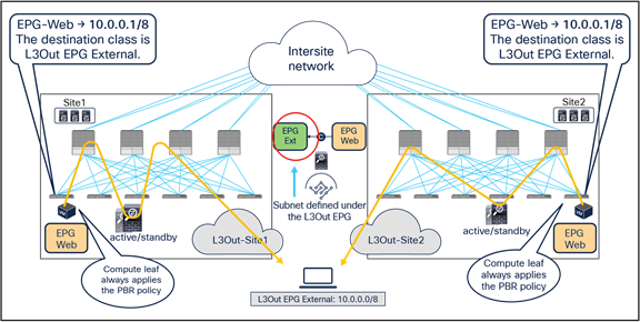
Destination IP subnet‒based classification for L3Out EPG
Figure 15 illustrates the service-graph PBR deployment for steering to the firewall the inbound flows between an external network and an internal Web EPG, in the example where the internal Web EPG and the L3Out are defined in the same VRF and with the default VRF configuration (that is, ingress policy enforcement).
This is the sequence of events needed for establishing inbound connectivity:
● The traffic is received from the external network on the border leaf nodes, and it is simply forwarded to the compute leaf nodes connected to the internal destination endpoints without applying any security policy (the policy-applied bit in the VXLAN header is set to 0 by the border leaf node). Figure 15, below, shows the deployment of a stretched internal EPG (and associated subnet), and how all the inbound flows are steered from the external network toward the L3Out defined in site1, even if the destination internal endpoint is connected in site2.
● Once the compute leaf nodes receive the traffic, they can apply the PBR policy (because the leaf nodes know both the source and destination class IDs), and the traffic is redirected to the local active firewall node specified in the PBR policy (or to one of the local nodes, based on the hashing decision, when deploying multiple active nodes per site).
● After the service nodes apply the configured security policy, the traffic is then sent back into the fabric and to the destination endpoints.
Use of PBR for inbound traffic flows (north-south)
The outbound flows are characterized by the following sequence of events:
● The destination endpoints send traffic back to the external destination, and the PBR policy is again applied on the same compute leaf nodes where it was applied for the inbound direction. This means that the return flows are steered toward the same service nodes that already saw the incoming connection (and hence created the connection state).
● Once the firewalls have applied the locally configured security policies, the traffic is then sent back to the fabric and forwarded to the external client through the local L3Out connection. This is the default behavior, unless specific routing policies are configured to ensure the outbound flow is sent through an L3Out connection deployed in a remote site.
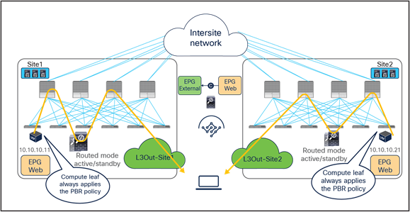
Use of PBR for outbound traffic flows (north-south)
When comparing the two previous figures, it is evident, regarding the endpoint sitting in site2, that there may be an “asymmetric” use of the L3Out connection (that is, inbound traffic uses L3Out-Site1, whereas outbound traffic is sent through L3Out-Site2), but there may be a “fully symmetric” use of the same service node for both directions of the communication. This is always the case for north-south intra-VRF communication, independently from the fact that the EPG and L3Out EPG are the consumer and/or provider of the contract with the associated service graph (with PBR enabled).
In the scenario where the internal EPG and the L3Out EPG are part of separate VRFs, it becomes instead important to define who is the consumer or the provider of the contract, because that would determine if the PBR policy gets applied on the compute leaf or on the border leaf. Thus, north-south inter-VRF service insertion with PBR in Multi-Site is supported only when the L3Out EPG is the provider, because that will ensure that the PBR policy is always (and only) applied on the compute leaf node (as it is the case for the intra-VRF north-south use case described above). This inter-VRF north-south use case is only supported with Multi-Site with Cisco ACI Release 4.2(5), 5.1(1), or later. Table 1 and Table 2 summarize the policy enforcement in the different use cases.
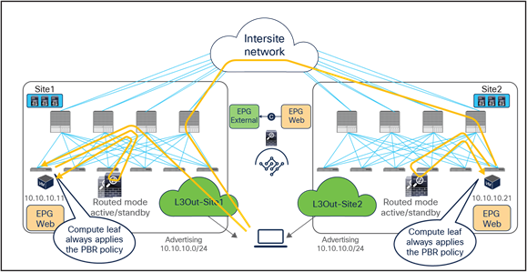
When you have available L3Out connections in both fabrics, the web server subnet stretched across sites is advertised through the border leaf nodes in both sites. As previously discussed, depending on the specific routing metric design, incoming traffic may be steered to the border leaf nodes of one of the sites. This suboptimal inbound traffic can be avoided by leveraging host-route advertisement to optimize the traffic path for ingress communication. With the use of service graph and PBR, such an approach represents only an optimization, but it is not necessary to avoid the establishment of asymmetric traffic across stateful services (as the previous example in Figure 15 and Figure 16 describes). Figure 17 illustrates how to optimize the inbound traffic flows: the destination IP address is the endpoint 10.10.10.11 located in Site1, and, because of the host route advertisement function, traffic originating from an external client can be selectively steered to Site1 and reach the destination leaf where the 10.10.10.11 endpoint is located. The destination leaf in Site1 then selects the local active PBR node, which sends traffic back to the destination. Similar behavior is achieved for traffic destined for the endpoint 10.10.10.21 in Site2.
Use of host route advertisement for ingress traffic optimization (north-south)
Note: In order to keep the configuration simple and to be able to apply a single EPG-to-L3Out contract, the External EPG associated to the L3Out (that is, the L3Out EPG) must be deployed as a “stretched” object associated to each site-specific L3Out. For more information, please refer to the ACI Multi-Site paper below: https://www.cisco.com/c/en/us/solutions/collateral/data-center-virtualization/application-centric-infrastructure/white-paper-c11-739609.html.
East-west traffic use case (EPG-to-EPG)
Figure 18 shows a typical Cisco ACI network design for east-west firewall insertion with PBR. This design is similar to that for the north-south firewall use case. The consumer Web EPG and the provider App EPG have a contract with an associated firewall service graph with PBR enabled in both directions.
East-west firewall with PBR design example (intra-VRF)
Note: Though this example is for an intra-VRF contract, an inter-VRF contract for east-west communication is also supported.
In this case, in order to avoid the creation of an asymmetric path across separate firewall nodes, we can leverage the fact that a contract between two EPGs always has a “consumer” and a “provider” side. It is hence possible to “anchor” the application of the PBR policy on only one side of the contract relationship, to be able to use the same firewall node for both directions of traffic. Starting from Cisco ACI Release 4.0(1), the “anchoring” of the application of the PBR policy is done on the provider leaf node, which is the leaf node where the endpoint providing the contract is locally connected.
This mandates that the provider leaf node always knows the class ID information for the consumer EPG, even if the specific endpoint information were not yet learned based on data-plane traffic activity (or if, for example, data-plane learning was disabled). Figure 19 highlights how this is achieved by configuring an IP prefix under the consumer EPG matching all the endpoints that are part of that EPG. This configuration could be easily applied in a “network-centric” deployment where a single EPG is associated to a BD (and its subnet), whereas the provisioning of specific /32 prefixes (or /128 for IPv6) would likely be required for “application-centric” scenarios.
Note: Prior to Cisco ACI Release 6.0(3d), /32 for IPv4 or /128 for IPv6 prefixes could not be provisioned under the consumer EPG because of CSCwa08796.
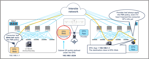
Destination IP prefix‒based classification for consumer EPG
In the example above, the IP prefix 192.168.1.0/24 provisioned under the consumer EPG is statically configured on the provider leaf node, together with the class ID of the consumer EPG. This ensures that the PBR policy can always be applied on the provider leaf to redirect the traffic to the local firewall, even if the provider endpoint was the one initiating a traffic flow toward the consumer endpoint.
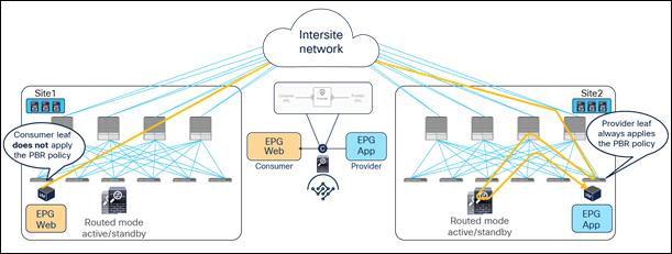
The examples in Figure 20 and Figure 21 show the specific behavior implemented starting from Cisco ACI Release 4.0(1), where the PBR policy is always applied on the provider leaf node.
● When the consumer Web endpoint sends traffic toward the App endpoints, the consumer leaf just forwards the traffic toward the provider leaf where the App endpoint has been discovered. The consumer leaf must not apply the PBR policy even if the consumer leaf can resolve the destination class ID of the provider EPG. In the case of an EPG-to-EPG contract with PBR, the zoning-rule for consumer-to-provider traffic has a special flag called “redirect override,” based on which the leaf avoids applying the policy unless the destination endpoint is locally learned. Thus, the use of the “redirect override” zoning-rule ensures that the provider leaf always applies the PBR policy even for the consumer-to-provider traffic.
● The traffic is received on the provider leaf node, and the PBR policy kicks in redirecting the traffic through the local active firewall node.
● Once the firewall has applied the locally configured security policies, the traffic is sent back toward the fabric and forwarded to the App endpoint.
Use of PBR for consumer-to-provider traffic flows (east-west)
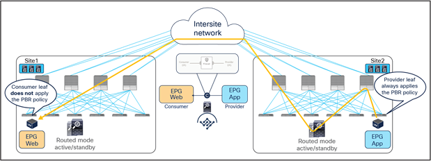
When the App endpoint replies back:
● The PBR policy is applied on the same provider leaf (otherwise the traffic could be steered to a different firewall node than the one used for the incoming direction). The traffic is therefore steered through the same firewall node that built the connection state by receiving the incoming traffic.
● Once the firewall has applied the security policy, the traffic is sent back toward the remote site and forwarded to the Web endpoint.
● The consumer leaf does not apply the policy, because this was already done on the provider leaf (the policy-applied bit in the VXLAN header is set to 1).
Use of PBR for provider-to-consumer traffic flows (east-west)
If the source endpoint and the destination endpoints are located in the same site, the traffic is always redirected to a local firewall node, and there is no traffic hair-pinning across sites (Figure 22).
East-west traffic within a site
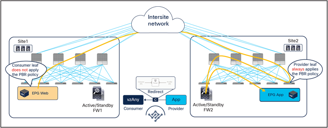
East-west and north-south traffic use case (vzAny-to-vzAny)
The deployment of this service graph with PBR use case requires the use of Cisco ACI Release 6.0(4c) or later and Cisco Nexus Dashboard Orchestrator Release 4.2(3e) or later. Figure 23 shows a sample Cisco ACI network design with vzAny-to-vzAny PBR. vzAny is both the consumer and the provider of a contract with a firewall service graph attached to it with PBR enabled in both directions.
Although this example shows just three EPGs (L3Out EPG, Web EPG, and App EPG), the VRF could have more EPGs in the same or different BDs, and the firewall could be inserted for all inter-EPGs communications because of the vzAny-to-vzAny contract with PBR.
North-south and east-west firewall with PBR design example (vzAny-to-vzAny)
When considering the use of vzAny-to-vzAny PBR for redirecting to the firewall intersite east-west traffic between internal EPGs, the difficulty of avoiding the creation of an asymmetric traffic path through the independent firewall services deployed across fabrics becomes immediately clear. This is because, differently from the previously discussed EPG-to-EPG PBR use case, when applying a vzAny-to-vzAny PBR contract, it is not possible anymore to distinguish the role of the consumer and the provider of the contract.
A different approach is therefore required in this case, and the chosen solution has been to redirect all east-west traffic flows to both firewall services deployed in the source and in the destination fabric (Figure 24).
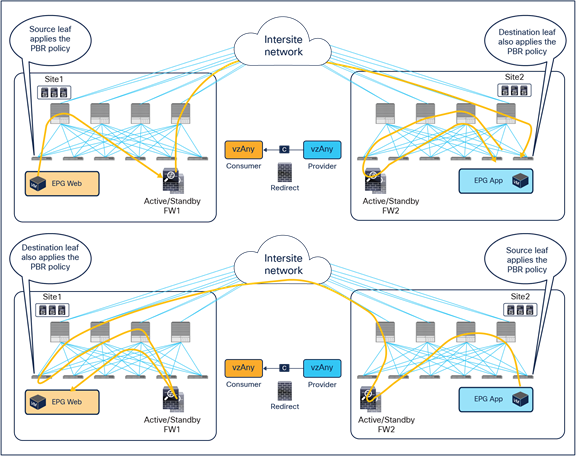
Use of ACI PBR to keep intersite traffic symmetric for the vzAny-to-vzAny PBR use case
The behavior shown above can be achieved if the PBR is applied on the source and destination leaf node for both directions of the same traffic flow. But for this to be possible, those leaf nodes should always know the class ID for the destination endpoint, and this cannot always be guaranteed under normal circumstances, hence some innovative functionalities have been introduced into ACI Multi-Site to achieve that.
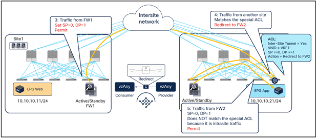
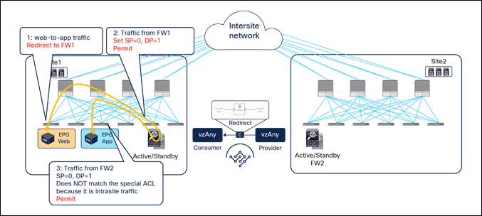
Figure 25 illustrates an example of the ideal behavior with a vzAny-to-vzAny PBR contract where intersite communication between an endpoint in Web EPG and an endpoint in App EPG is steered through the firewall services in both the source and the destination sites.
● When the Web endpoint sends traffic toward the App endpoint, the ingress leaf in site1 redirects the traffic to the local active firewall node. As mentioned, for this to be possible we are assuming here that the source leaf node has all the required information (that is, the source and destination class IDs) to enforce the PBR policy.
● Once the firewall in the source site has applied the locally configured security policies, the traffic is sent to the destination leaf. The service leaf in site1 sets special flags[2] in the VXLAN header, to indicate that the local firewall has been inserted and has applied its security policy.
● When the traffic arrives to the destination leaf in site2, the special flags setting and the specific source VTEP address convey the information to the leaf that the firewall in the remote source site has already seen the traffic. The leaf can therefore just apply the PBR policy to redirect the traffic through the local active firewall node.
● After the local firewall has applied its security policy, the traffic is sent to the destination leaf node again. The service leaf in site2 also set the special flags in the VXLAN header (as was done by the service leaf nodes in the source site) to indicate the fact that the local firewall has seen the traffic. However, this information is now ignored by the destination leaf because this is intrasite VXLAN traffic (that is, it originated from a local service leaf node), so the destination leaf must simply forward it to the destination endpoint.
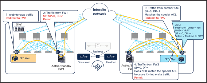
Use of PBR for Web-to-App traffic flows (vzAny-to-vzAny)
The insertion of the firewall services in both sites must also be done for the return traffic flow (Figure 25)
● When the App endpoint sends traffic toward the Web endpoint, the ingress leaf in site2 redirects traffic to the local active firewall node. Again, we are assuming that the ingress leaf knows the destination class ID information to be able to locally enforce the PBR policy.
● Once the firewall has applied its locally configured security policy, the traffic is sent to the destination leaf. The service leaf in site2 encapsulates the traffic with special flags properly set in the VXLAN header.
● When the traffic arrives to the leaf in site1, it is again redirected through the local active firewall node because of the special flags setting in the traffic received from the remote site.
● After the firewall has applied the locally configured security policies, the traffic is sent back to the destination leaf. The service leaf in site1 also set the special flags in the VXLAN header, but the destination leaf does not redirect traffic again because it is intrasite traffic.
Use of PBR for App-to-Web traffic flows (vzAny-to-vzAny)
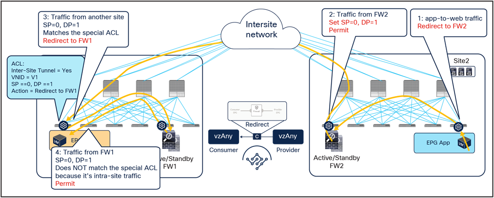
For both directions of the flow, the redirection on the ingress leaf node is predicated on the leaf’s knowledge of the class ID of the destination endpoint. If, for whatever reason, that is not the case, the ingress leaf cannot apply the policy, and a different mechanism is required to ensure redirection of traffic to the firewall services in both the source and the destination site.
As shown in Figure 27, if the ingress leaf cannot apply the PBR policy, the traffic is implicitly permitted, and the Policy-Applied (PA) bit in the VXLAN header is not set (PA = 0). The traffic is forwarded across sites and received by the destination leaf in the remote site, which will redirect traffic back to the active firewall node in the source site. This is because setting the PA bit to 0 indicates that the policy was not applied by the ingress leaf (and consequently not sent to the firewall in that site), and the destination leaf redirects the flow back to the firewall in the source site. After the firewall in site1 has applied its locally configured policy, the traffic is sent back to the destination leaf. The remaining flow (Figure 28) is then the same as already shown in Figure 25 (the traffic is redirected to the local firewall in site2 before reaching the destination endpoint).
Hair-pinning of traffic when the consumer leaf cannot apply the PBR policy
Traffic forwarded back to the destination site
The traffic hair-pinning shown above, while not creating asymmetricity through the different firewall nodes, represents suboptimal data-path behavior. In order to eliminate it, an additional functionality named “conversational learning” has been implemented in Cisco ACI fabric for this vzAny-to-vzAny PBR use case.
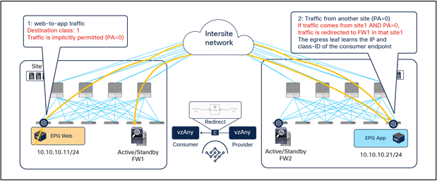
Figure 29 shows how the reception of traffic with the PA bit set to 0 on the destination leaf triggers (in parallel to the data-plane traffic redirection shown in Figure 27 the origination of a control packet containing information about the destination endpoint IP address and class ID. This control packet is sent to the source leaf in site1, which receives it and installs the destination endpoint information on the source leaf in site1.
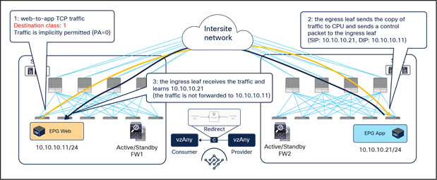
After the ingress leaf has learned the destination endpoint information, traffic is forwarded optimally from the source to the destination site, as previously shown in Figure 24.
It is worth noticing that if the east-west flow is between two endpoints connected to the same fabric, the traffic is redirected by either the source or the destination leaf. The endpoint IP learning status does not matter, because the local PBR destination is always used regardless of which leaf applies the PBR policy.
Intrasite traffic (vzAny-to-vzAny)
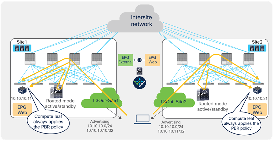
Applying the policy on the ingress leaf node, which is a requirement for east-west communication in the vzAny-to-vzAny PBR use case, may represent a problem for the redirection of north-south traffic flows without inbound traffic path optimization. To better understand this issue, let’s consider the scenario depicted in Figure 31.
Inbound flow redirected to both firewall services
Inbound traffic is received in site1 even if the destination is the Web EPG endpoint connected to site2. The border leaf node in site1 applies the PBR policy (because it is the ingress leaf), and traffic is redirected first to the firewall in site1 and then to the firewall in site2, as expected for the vzAny-to-vzAny use case.
Figure 32 shows instead the return traffic flow, from the Web EPG endpoint in site2 to the external destination.
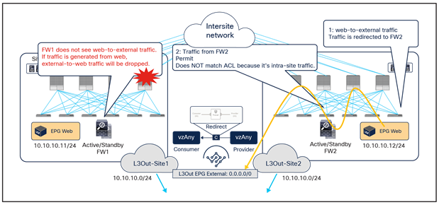
Outbound flow redirected only to the firewall service in site2
The outbound flow can only be redirected to the firewall service in site2, and this causes an asymmetric behavior that will cause traffic drop when the north-south communication is initiated by the Web endpoint.
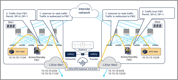
The solution to this problem, highlighted in Figure 33, consists in enabling host-based routing advertisement so that inbound traffic paths are optimized. Notice that this means that, for north-south traffic redirection with the vzAny-to-vzAny PBR use case, the redirection should only happen to the firewall located in the site where the internal endpoint is connected.
East-west and north-south traffic use case (vzAny-to-EPG)
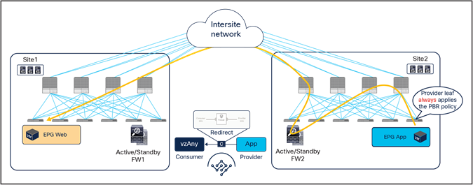
As in the case for the previous vzAny-to-vzAny scenario, this service graph PBR option also requires Cisco ACI Release 6.0(4c) or later and Cisco Nexus Dashboard Orchestrator Release 4.2(3e) or later. Figure 34 shows a sample Cisco ACI network design for east-west and north-south firewall insertion with vzAny-to-EPG PBR. App EPG and vzAny have a contract with a firewall service graph attached to it, with PBR enabled in both directions.
Although the figure below shows just three EPGs (L3Out EPG, Web EPG, and App EPG), the VRF could have more EPGs in the same or in different BDs, and the firewall is inserted for the communication between all the EPGs in the VRF and the App EPG, as a result of the vzAny-to-App contract with PBR.
East-west firewall with PBR design example
Figure 35 illustrates an example of a service-graph PBR deployment for steering to the firewall the intersite communications between an endpoint in Web EPG and an endpoint in App EPG. In this case, in order to avoid the creation of an asymmetric path across separate firewall nodes, the policy must be applied on the provider leaf node for both directions of the same flow, similarly to the east-west traffic use case with EPG-to-EPG PBR. However, for this use case this requirement can be satisfied without provisioning the IP prefix under the consumer EPGs.
● When the Web endpoint (representing a consumer EPG part of vzAny) sends traffic toward an App endpoint, the consumer leaf just forwards the traffic toward the provider leaf where the App endpoint has been discovered. As previously mentioned for the EPG-to-EPG PBR use case, the consumer leaf is programmed for not applying the PBR policy, which uses a “redirect override” flag.
● The PBR policy kicks in on the provider leaf, and the traffic gets redirected through the local active firewall node.
● Once the firewall has applied its locally configured security policy, the traffic is sent back toward the fabric and forwarded to the App endpoint.
Use of PBR for consumer-to-provider traffic flows (vzAny-to-EPG)
The same firewall is inserted for the return traffic flow (Figure 36).
● The PBR policy is applied on the provider leaf, and the traffic is steered through the same firewall node that built the connection state by receiving the incoming traffic. This is under the assumption that the provider leaf knows the class ID for the consumer endpoint. If that was not the case, the traffic would be sent directly to the consumer leaf in site1, which would redirect the flow to the remote firewall in site2 and generate the control-plane packet required for conversation learning similar to the example shown in Figure 29 (the same behavior already discussed for the previous vzAny-to-vzAny PBR use case).
● Once the firewall has applied its local security policy, the traffic is sent back toward the remote site and forwarded to the Web endpoint.
● The consumer leaf does not apply the policy, because this was already done on the provider leaf.
Use of PBR for provider-to-consumer traffic flows (vzAny-to-EPG)
North-south traffic use case (vzAny-to-L3Out)
This service-graph option also requires Cisco ACI Release 6.0(4c) and Cisco Nexus Dashboard Orchestrator Release 4.2(3e) or later. Figure 37 shows a sample Cisco ACI network design for north-south firewall insertion with vzAny-to-L3Out PBR. L3Out1 EPG and vzAny have a contract with a firewall service graph attached to it, with PBR enabled in both directions.
Note: If the VRF has another L3Out EPG (L3Out2 EPG in this example), that L3Out EPG is also part of vzAny, thus a vzAny-to-L3Out PBR contract can also be used for L3Out-to-L3Out firewall insertion.
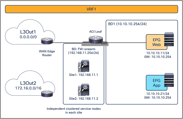
North-south firewall with PBR design example (vzAny-to-L3Out)
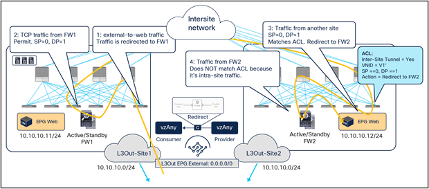
Figure 38 illustrates an example of service-graph PBR deployment for steering to the firewall the intersite communication between an endpoint in Web EPG and an external endpoint in the L3OutEPG. In this case, in order to avoid the creation of asymmetric firewall insertion, the traffic is redirected to the firewall services in both source and destination sites, which is similar to the behavior described for the vzAny-to-vzAny PBR use case.
● When a Web endpoint sends traffic toward an external endpoint in the L3OutEPG, the ingress leaf in site1 redirects traffic through the local active firewall node. Because an L3Out EPG classification is based on the IP prefix, it should always be possible for the ingress leaf to resolve the destination L3Out EPG class ID.
● Once the firewall has applied its locally configured security policy, the traffic is sent to the destination leaf. The service leaf in site1 permits traffic with special flags in the VXLAN header, which indicates that the firewall was inserted. Please refer to the footnote on page 29 for more information on the use of those flags.
● When the traffic arrives to the destination leaf in site2, it is again redirected through the local active firewall node because the special flags are set and the traffic is received from another site.
● After the firewall has applied its locally configured security policy, the traffic is sent to the destination leaf. The service leaf in site2 also set the special flag in the VXLAN header, but the destination leaf doesn’t redirect traffic again because the traffic is intrasite.
Use of PBR for consumer-to-provider traffic flows (vzAny-to-L3Out)
The same firewall services in both sites must be inserted for the return flow (Figure 39).
● When the external endpoint sends traffic toward the Web endpoint, the ingress leaf in site2 redirects traffic through the local active firewall node. This is under the assumption that the provider leaf knows the class ID information for the consumer endpoint. If that was not the case, the traffic would be sent directly to the consumer leaf in site1, which would redirect the flow to the remote firewall in site2 and generate the control-plane packet required for conversation learning similar to the example shown in Figure 29 (the same behavior was already discussed for the previous vzAny-to-vzAny PBR use case).
● Once the firewall has applied its locally configured security policy, the traffic is sent to the destination leaf. The service leaf in site2 permits the traffic with special flags set in the VXLAN header.
● When the traffic arrives to the destination leaf in site1, traffic is again redirected through the local active firewall node because of the special flags set in the traffic received from another site.
● After the firewall has applied its locally configured security policy, the traffic is sent to the destination leaf. The service leaf in site1 also set the special flags in the VXLAN header, but the destination leaf does not redirect traffic again because the traffic is intrasite.
Use of PBR for provider-to-consumer traffic flows (vzAny-to-L3Out)
If the traffic is intrasite, it is redirected by either the source or the destination leaf. The endpoint IP learning status does not matter because the local PBR destination is always used regardless of which leaf applies the PBR policy, which is similar to the scenario shown in Figure 30.
Transit traffic use case (L3Out-to-L3Out)
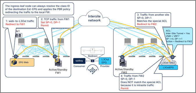
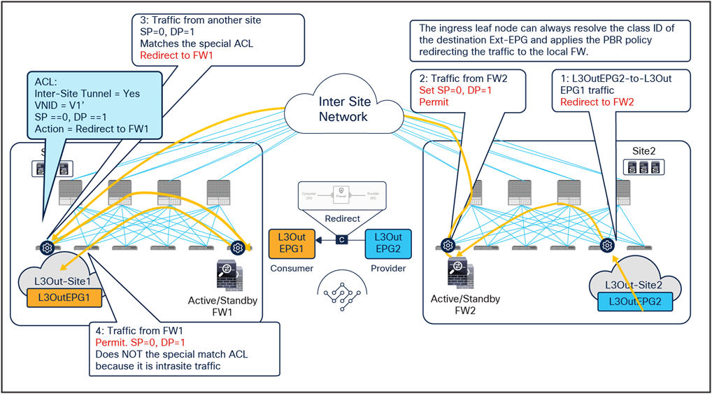
This service-graph option also requires Cisco ACI Release 6.0(4c) and Cisco Nexus Dashboard Orchestrator Release 4.2(3e) or later. The figure below shows a sample Cisco ACI network design with L3Out-to-L3Out PBR. L3Out EPG1 and L3Out EPG2 have a contract with a firewall service graph attached to it, with PBR enabled in both directions.
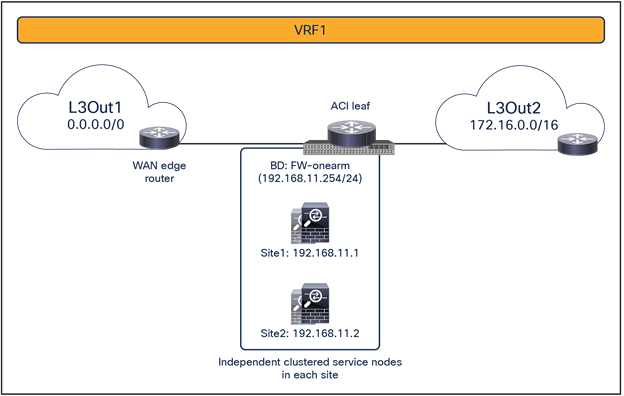
Transit traffic with PBR design (L3Out-to-L3Out)
Figure 41 illustrates an example of a service-graph PBR deployment for steering to the firewall the intersite communications between external endpoints in different L3Outs. In this case, in order to avoid the creation of an asymmetric firewall insertion, traffic is redirected to the firewall nodes in both source and destination sites, which is similar to the vzAny-to-vzAny PBR use case described in Figure 24.
● When an external endpoint sends traffic toward another external endpoint in a different L3Out EPG, the ingress border leaf in site1 redirects traffic through the local active firewall node. Because an L3Out EPG classification is based on the IP prefix, it should always be possible for the ingress leaf to resolve the destination L3Out EPG class ID.
● Once the firewall has applied its locally configured security policy, the traffic is sent to the destination leaf. The service leaf in site1 permits traffic with special flags in the VXLAN header, which indicates that the firewall was inserted (see the footnote on page 29 for more information).
● When the traffic arrives to the destination leaf in site2, traffic is again redirected through the local active firewall node because the special flags are set for traffic received from another site.
● After the firewall has applied its locally configured security policy, the traffic is sent to the destination leaf. The service leaf in site2 also set the special flags in the VXLAN header, but the destination leaf does not redirect traffic again because the traffic is intrasite.
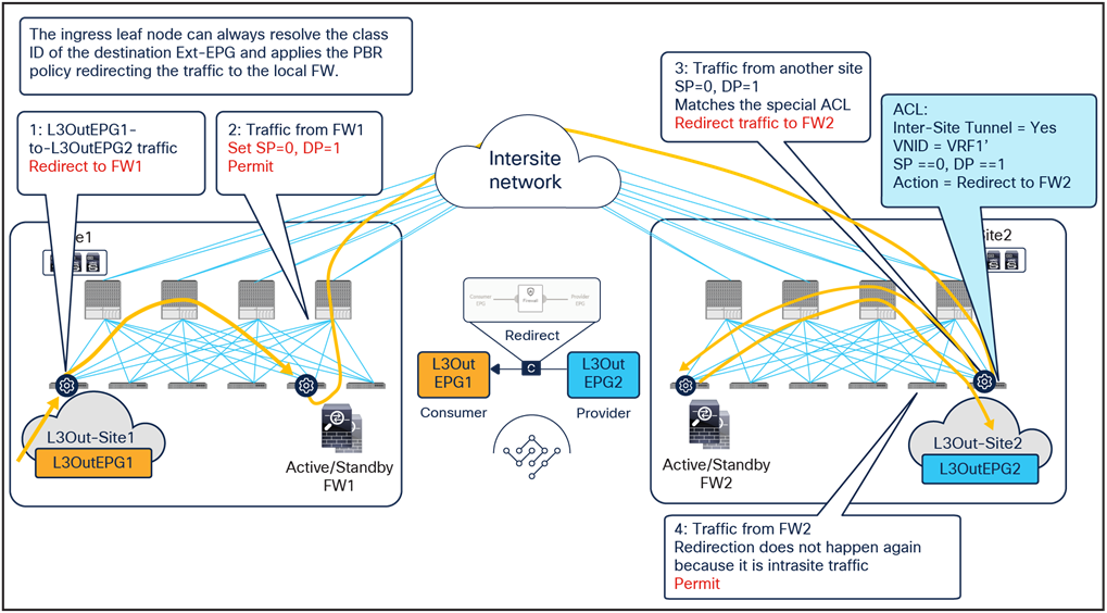
Use of PBR for L3Out1-to-L3Out2 traffic flows (L3Out-to-L3Out)
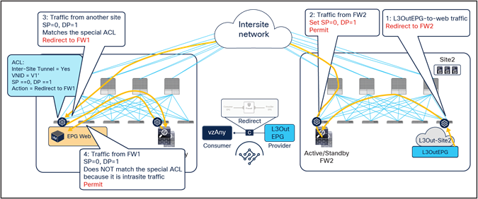
The same firewall services in both sites are inserted for the return flow (Figure 42).
● When the external endpoint sends traffic toward the other external endpoint, the ingress border leaf in site2 redirects traffic through the local active firewall node. Because an L3Out EPG classification is based on the IP prefix, it should always be possible for the ingress leaf to resolve the destination L3Out EPG class ID.
● Once the firewall has applied its locally configured security policy, the traffic is sent to the destination leaf. The service leaf in site2 permits traffic with special flags in the VXLAN header.
● When traffic arrives at the destination leaf in site1, traffic is again redirected through the local active firewall node because the special flags are set for traffic received from another site.
● After the firewall has applied its locally configured security policy, the traffic is sent to the destination leaf. The service leaf in site1 also set the special flags in the VXLAN header, but the destination leaf does not redirect traffic again because the traffic is intrasite.
Use of PBR for L3Out2-to-L3Out1 traffic flows (L3Out-to-L3Out)
If the traffic is intrasite, it is redirected by either the source or the destination leaf, which is similar to the scenario shown in Figure 30.
Load balancer with Source Network Address Translation (SNAT)
This section explains load-balancer insertion with Source Network Address Translation (SNAT) for north-south and east-west traffic use cases. In this deployment model, applying a PBR policy is not required because both incoming traffic flows (toward the VIP address) and return traffic flows (toward the IP address translated by SNAT) are destined to the load balancer and do not need redirection services.
Though this document uses a contract with a load-balancer service graph as an example, a service graph is not mandatory for this design. The main differences between the use of a service graph without PBR and the non-use of a service graph are the following:
● Use of service graph without PBR
As shown on the left side of Figure 43, using the service graph without PBR brings the advantage of being able to simply define a contract between the consumer (clients) and the provider (server farm). The EPGs for the load-balancer interfaces are automatically created through the service graph, together with the required contracts to ensure traffic can flow in both directions.
● Non-use of service graph
In this case, two different contracts are required. The first one is between the consumer EPG (clients) and the EPG for the interface of the load balancer facing the clients. The second is between the EPG for the interface of the load balancer performing SNAT and the provider EPG (server farm) associated to the Virtual IP (VIP). If there is no contract security requirement, use of the same EPG for clients and the load balancer, and servers and the load balancer is also an option.
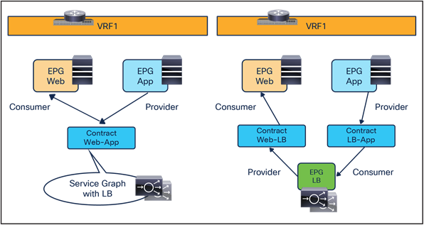
Load-balancer insertion with (left) and without (right) service graph
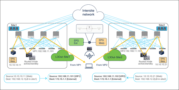
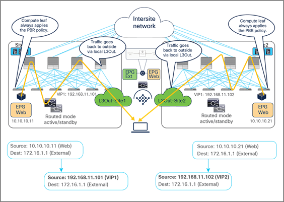
North-south traffic use case (EPG-to-L3Out)
Figure 44 shows a sample Cisco ACI network design for north-south-routed load-balancer insertion with SNAT. The consumer L3Out EPG and the provider Web EPG have a contract with a load-balancer service graph (without PBR). The endpoints in the Web EPG are the real servers that are part of the server farm associated to the VIP of the load balancer. You can have multiple load balancers, which can be represented by multiple high-availability pairs deployed in separate sites.
The assumption here is that each load balancer pair has assigned a unique VIP address that is part of the same service BD, as shown in the example below. In this scenario, Global Server Load Balancing (GSLB) can be used for load balancing access to a specific application through multiple VIPs.
Note: If a service graph is not defined, using the same service BD for each load balancer pair is not mandatory. Each load-balancer pair can use a unique VIP address in different service BDs. Also, without a service graph, an inter-VRF design is also possible.
Example of a north-south load balancer with a SNAT design
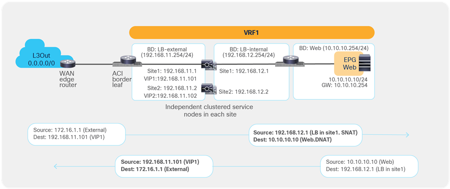
Figure 45 illustrates an example of communication between the external network and an internal Web EPG in an ACI Multi-Site deployment where we have two connections: one is between the external network and the VIP (the frontend connection), and the other one is between the load-balancer internal IP address and the real servers in the Web EPG (the backend connection). In this example, the internal Web EPG and the L3Out are defined in the same VRF.
● The incoming traffic originating from the external client is destined to the VIP, so it will be received on the L3Out connection of one of the connected sites and will then reach the load balancer without PBR as long as the VIP is reachable (this is basic forwarding behavior).
● The load balancer changes the destination IP to one of the real servers associated to the VIP. In this example, the load balancer also translates the source IP to the SNAT IP owned by the load balancer.
● After that, the traffic is forwarded to the real server.
Note: The suboptimal inbound traffic can be avoided by leveraging host-route advertising to optimize the traffic path for ingress, if the VIP of the load balancer belongs to a stretched subnet. Alternatively, it is possible to use VIP addresses in separate IP subnets for load balancers deployed in different sites. In the case of service graph, the separate IP subnets need to be configured under the same service BD because an L2-stretched service BD is required for a service graph.
Load balancer with SNAT inbound traffic flows (north-south)
Because the return traffic is destined to the SNAT IP owned by the load balancer that handled the incoming traffic flow, PBR is not required for the return traffic either.
● The load balancer receives the traffic from the Web real server endpoint and changes the source and destination IP addresses (the source becomes the VIP, the destination becomes the external client).
● The traffic is sent back to the fabric and forwarded to the external client through a local L3Out connection (unless a specific configuration is provisioned to prefer a remote L3Out connection to communicate with the external client).
Though there may be an “asymmetric” use of the L3Out connection (for example, for VIP2, inbound traffic uses L3Out-Site1, whereas outbound traffic is sent through L3Out-Site2), there is always a “fully symmetric” use of the same service node for both legs of the communication.
Load balancer with SNAT inbound traffic flows (north-south)
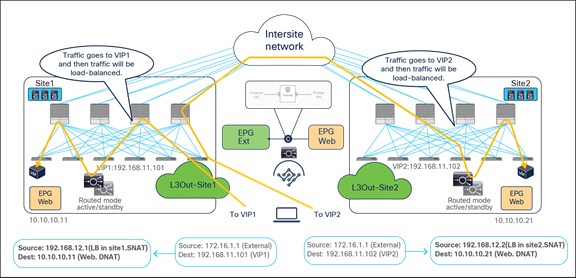
The examples above show the load balancer and the real server as part of the same site, but in this use case they could also be deployed in different sites (Figure 47 and Figure 48). This is because the VIP, the SNAT IP, and the real servers’ addresses are always reachable through regular forwarding from different sites. That said, the use of a local real-server farm is ideal in terms of traffic path optimization.
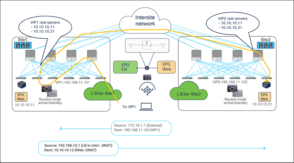
Load balancer with SNAT inbound traffic flows (with VIP and real server in different sites)
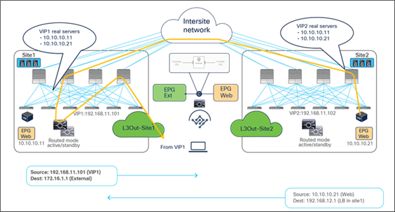
Load balancer with SNAT outbound traffic flows (with VIP and real server in different sites)
East-west traffic use case (EPG-to-EPG)
Figure 49 shows a typical Cisco ACI network design for east-west-routed load-balancer insertion with SNAT. This design is similar to that for the north-south-routed load-balancer use case. In this example, the consumer Web EPG and the provider App EPG have a contract with a load-balancer service graph. Endpoints in the App EPG are real servers associated to the VIP on the load balancer.
As previously discussed for the north-south use case, the assumption is that each load balancer pair has assigned a unique VIP address that is part of the same service BD. If a service graph is not defined, each load balancer pair can use a unique VIP address in different service BD. Also, even if this example focuses on an intra-VRF contract, an inter-VRF contract for east-west communication is also supported.
Example of an east-west load balancer with a SNAT design
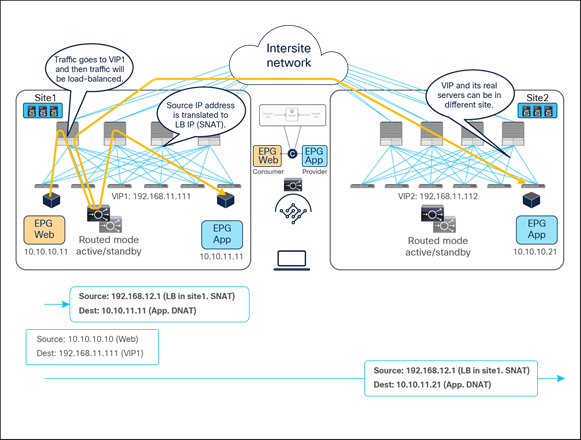
Figure 50 illustrates an example of east-west communication between a consumer EPG Web and a provider EPG App in a Multi-Site scenario where we have two connections: one is between the Web endpoint and the VIP (the frontend connection) and the other is between the load balancer and the real servers in the App EPG (the backend connection).
● The traffic originating from the Web endpoint is destined to the VIP, so it will reach the load balancer without requiring PBR as long as the VIP is reachable.
● The load balancer changes the destination IP to one of the real servers associated to the VIP. At the same time, the load balancer translates the source IP to the SNAT IP owned by the load balancer.
● The traffic is then sent back to the fabric and forwarded to the real server.
Load balancer with SNAT incoming traffic flows (east-west)
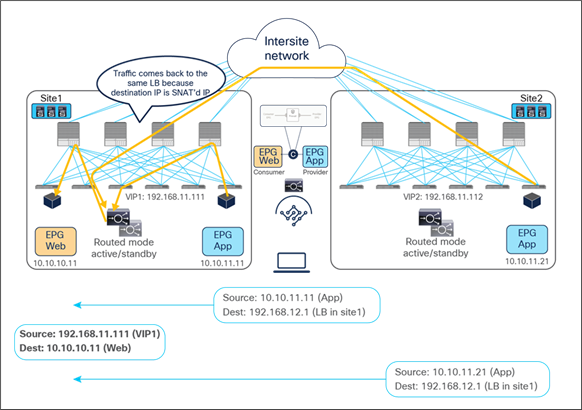
For the provider-to-consumer traffic direction:
● The return traffic originated by the App real server is destined to the SNAT IP owned by the load balancer that took care of the incoming traffic; therefore, applying the PBR policy is not required for the return traffic either.
● The load balancer changes the source and destination IPs and sends the traffic back to the fabric.
● The traffic is forwarded back to the consumer endpoint.
Load balancer with SNAT return traffic flows (east-west)
Note: Though, in this example, the load balancer and the real server are in the same site, they can be in different sites, similar to the north-south-routed load-balancer insertion example earlier.
The use of SNAT is very handy to ensure that the return traffic goes back to the same load balancer that handled the incoming flow, therefore simplifying the design. However, a possibly undesirable consequence is that real servers lose visibility into the client’s source IP address. When such visibility is a design requirement, you should avoid using SNAT on the load balancer, in order to ensure preserving the client’s source IP. This mandates the introduction of PBR to properly steer the return traffic through the same load balancer that handled the first leg of the communication, as discussed in the next section.
Load balancer without SNAT (use of PBR for the return traffic)
In this deployment model, PBR is required for the return traffic between the real servers and the clients, because the load balancer does not perform SNAT for incoming traffic. The Incoming traffic flow destined to the VIP still does not require PBR and leverages basic forwarding.
There are two important considerations for deploying this design option with ACI Multi-Site:
● The load balancer and the real-server farm where traffic is load balanced must be deployed in the same site.
● Cisco ACI Release 4.0(1) or later is required for the EPG-to-EPG and EPG-to-L3Out use cases. For the vzAny-to-EPG use case, Cisco ACI Release 6.0(4c) and Cisco Nexus Dashboard Orchestrator Release 4.2(3e) or later are needed instead.
North-south traffic use case (EPG-to-L3Out)
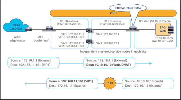
Figure 52 shows a sample Cisco ACI network design for north-south-routed load balancer insertion without SNAT. The consumer L3Out EPG and the provider Web EPG have a contract with associated a service graph with PBR for the return traffic flow. Endpoints in the Web EPG are the real servers associated to the VIP of the load balancer. There can be multiple load balancers, which can be represented by multiple high-availability pairs deployed in separate sites.
The usual assumption here is that each load balancer gets assigned a unique VIP address that is part of the same BD and that Global Server Load Balancing (GSLB) is then used for load balancing traffic for a given application to multiple VIPs. Although the figure below illustrates an intra-VRF design, the definition of Web EPG and L3Out EPG in different VRFs is also a valid design. In this multi-VRF scenario, the service BD where the load balancer is connected must be in either the consumer or the provider VRF.
Example of a north-south load-balancer design without SNAT
Figure 53 illustrates an example of an inbound traffic flow between the external network and an internal Web EPG in a Multi-Site deployment where we have two connections: one is between the external client and the VIP (the frontend connection) and the other is between the load balancer and the real servers that are part of the Web EPG (the backend connection).
● The incoming traffic originated from the external client and destined to the VIP is received on the L3Out connection of a given site, and reaches the load balancer without requiring PBR as long as the VIP is reachable (this is basic intrasite or intersite forwarding).
● The load balancer changes the destination IP to one of the real servers associated to the VIP, but leaves unaltered the source IP addresses (representing the external client) and forwards the traffic back to the fabric.
● The traffic is then forwarded to the real server, which must be deployed in the local site. As clarified below, this is needed to ensure that PBR can steer the return flow to the same load balancer that handled the incoming traffic.
As usual, the suboptimal inbound traffic shown for communicating with the VIP2 could be avoided by leveraging host-route advertisement to optimize the traffic path for ingress communication or by taking the VIP addresses of the load balancers deployed in separate sites from different IP subnets. Note that the service BD must be L2-stretched when using a service graph. Thus, multiple IP subnets must be provisioned for the same service BD to use VIP addresses from different IP subnets.
Load balancer without SNAT inbound traffic flows (north-south)
For the outbound direction, the traffic is destined to the original client’s IP address connection; therefore, PBR is required to steer the return traffic back to the load balancer. Otherwise the external client would receive the traffic with the source IP being the real server’s IP instead of the VIP. Such traffic will be dropped because the external client did not initiate traffic to the real server IP.
● The Web EPG sends traffic back to the external client. The PBR policy is always applied on the compute leaf node (provider leaf) where the Web endpoint is connected, so it can only redirect the traffic to a local load-balancer. This is the reason why the VIP and the real servers must be in the same site in this deployment model. The provider leaf always applies the PBR policy, because the IP prefix identifying the external clients and associated to the L3Out EPG is statically configured (with its class ID) on that leaf node.
● The load balancer changes only the source IP address to match the locally defined VIP and sends the traffic back to the fabric.
● The traffic is forwarded toward the external client leveraging, by default, a local L3Out connection.
Load balancer without SNAT outbound traffic flows (north-south)
Though there may be an “asymmetric” use of the L3Out connections (that is, for VIP2, inbound traffic uses L3Out in site1, whereas outbound traffic is sent through L3Out in site2), there is always a “fully symmetric” use of the same service node for both legs of the communication as long as the load balancer and the real servers are deployed in the same site. Otherwise the return traffic would be redirected to the load balancer in a different site and lose traffic symmetricity.
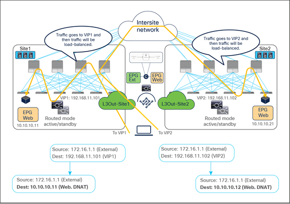
Figure 55 and Figure 56 illustrate an example of this problem: the load balancer in site1 has both local site endpoint 10.10.10.11 and remote site endpoint 10.10.10.21 as real servers associated to VIP1. If the incoming traffic to VIP1 is load balanced to 10.10.10.21 in site2, the PBR policy for the return traffic enforced on the provider leaf in site2 would redirect the traffic to the local load balancer, creating traffic asymmetry.
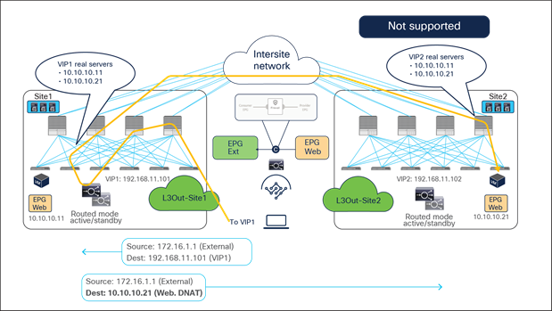
Load balancer without SNAT inbound traffic flows (Having the VIP and real server in different sites is not supported).
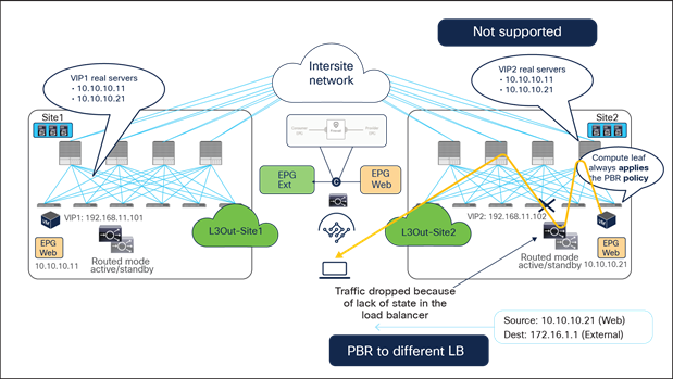
Load balancer without SNAT inbound traffic flows (Having the VIP and real server in different sites is not supported).
East-west traffic use case (EPG-to-EPG)
Figure 57 shows a typical Cisco ACI network design for east-west-routed load-balancer insertion without SNAT. This design is similar to that for the north-south load-balancer use case previously discussed. The consumer Web EPG and the provider App EPG have a contract with a load-balancer service graph. The endpoints in App EPG are real servers associated to the VIP on the load balancer and must be connected in the same site where the VIP is active.
The assumption here is that the VIP is in the same BD, each load balancer pair has a unique VIP address, and Global Server Load Balancing (GSLB) is used for load balancing to multiple VIPs.
Example of east-west load balancer design without a SNAT
Figure 58 illustrates an example of east-west communication between a consumer EPG Web and a provider EPG App in an ACI Multi-Site architecture. Here we have two connections: one is between a Web endpoint and the VIP (the frontend connection), and the other is between the load balancer and the real servers in the App EPG (the backend connection).
● The consumer-to-provider traffic is destined to the VIP, so the traffic reaches the load balancer without the need of PBR as long as the VIP is reachable. Notice how the VIP could be locally deployed or available in a remote site.
● The load balancer changes the destination IP to one of the real servers associated to the VIP, but it does not alter the source IP (since SNAT is not enabled). The traffic is then sent back to the fabric.
● The traffic is forwarded to the real server, which must be connected in the same site.
In the example below, the Web endpoint accesses the VIP addresses of both of the load balancers deployed in the local and remote sites, which then redirect traffic to local server farms.
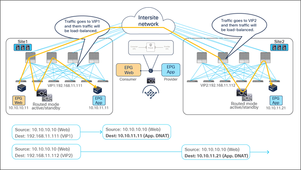
Load balancer without SNAT incoming traffic flows (east-west)
Because the return traffic is destined to the original source IP of the Web endpoint, PBR is required to force the return traffic through the same load balancer used for the consumer-to-provider direction.
● The App endpoint sends the traffic back to the Web endpoint PBR, and the policy is applied on the provider leaf node where the App endpoint is connected. This ensures that the return traffic is steered toward the same load balancer because the load balancer and the real server must always be in the same site in this deployment model. Otherwise the return traffic would be redirected to a different load balancer from the one used for the first leg of the communication, thus causing loss of traffic symmetricity (similar to what was shown previously, in Figure 55 and Figure 56). Since the clients are part of an internal EPG, the provider leaf cannot resolve the destination class ID if the client IP is not yet learned. Hence, the provisioning of an IP prefix under the consumer EPG is required, similarly to the EPG-to-EPG PBR use case for firewall insertion previously discussed.
● The load balancer changes only the source IP address to match the locally defined VIP and sends the traffic back to the fabric.
The traffic is forwarded toward the Web endpoint that could be locally connected or deployed in a remote site.
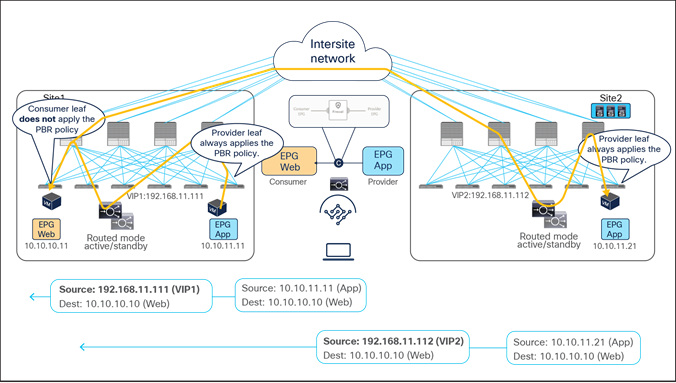
Load balancer without SNAT return traffic flows (east-west)
East-west and north-south traffic use case (vzAny-to-EPG)
This service-graph option requires Cisco ACI Release 6.0(4c) or later and Cisco Nexus Dashboard Orchestrator Release 4.2(3e) or later.
Figure 60 shows a sample Cisco ACI network design for east-west and north-south‒routed load-balancer insertion without SNAT. This design is similar to that for the north-south and east-west load-balancer use cases previously discussed. The consumer vzAny and the provider App EPG have a contract with a load-balancer service graph where PBR is enabled only for the provider-to-consumer direction. The endpoints in the App EPG are real servers associated to the VIP on the load balancer and must be connected in the same site where the VIP is active.
The assumption here is that the VIP is in the same BD, each load-balancer pair has a unique VIP address, and Global Server Load Balancing (GSLB) is used for load balancing to multiple VIPs.
Although the figure below has just three EPGs (L3Out EPG, Web EPG, and App EPG), the VRF could have more EPGs defined in the same or different BDs. Because of the vzAny-to-EPG contract with PBR, all the traffic flows initiated by clients that are part of those EPGs and destined to the load-balancer VIP will have the return traffic redirected to the load balancer.
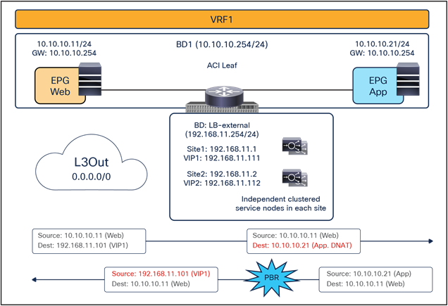
Example of east-west and north-south load balancer without a SNAT design
Figure 61 illustrates an example of east-west communication between a consumer vzAny and a provider EPG App in an ACI Multi-Site architecture. Here we have two connections: one is between a Web endpoint and the VIP (the frontend connection), and the other is between the load balancer and the real servers in the App EPG (the backend connection).
● The consumer-to-provider traffic is destined to the VIP, so the traffic reaches the load balancer without the need of PBR as long as the VIP is reachable. Notice how the VIP could be locally deployed or available in a remote site.
● The load balancer changes the destination IP to one of the real servers associated to the VIP, but it does not alter the source IP (since SNAT is not enabled). The traffic is then sent back to the fabric.
● The traffic is forwarded to the real server, which must be connected in the same site.
In the example below, the Web endpoint accesses the VIP addresses of both of the load balancers deployed in the local and remote sites, which then redirect the traffic to a local server farms.
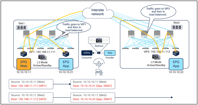
Load balancer without SNAT incoming traffic flows (east-west)
Because the return traffic is destined to the original source IP of the Web endpoint, PBR is required to force the return traffic through the same load balancer used for the consumer-to-provider direction.
● The App endpoint sends the traffic back to the Web endpoint PBR, and the policy is applied on the provider leaf node where the App endpoint is connected. This ensures that the return traffic is steered toward the same load balancer because the load balancer and the real server must always be in the same site in this deployment model. Otherwise the return traffic would be redirected to a different load balancer from the one used for the first leg of the communication, thus causing loss of traffic symmetricity (similar to what was shown previously, in Figure 55 and Figure 56). Notice that the provider leaf is always capable of applying the PBR policy for return traffic destined to external clients (because of the usual static programming on the leaf for L3Out EPGs classification prefixes). If the clients are instead part of internal EPGs, the provider leaf may not be able to apply the PBR policy. However, there is no need to specify the consumer EPG subnets, unlike the EPG-to-EPG use case. Traffic will be forwarded to the consumer leaf once and then will be redirected back to the load balancer in the provider site, similar to what was shown for the firewall use case in Figure 27 and Figure 28. Conversational learning will then be used to remove the traffic.
● The load balancer changes only the source IP address to match the locally defined VIP and sends the traffic back to the fabric.
The traffic is forwarded toward the Web endpoint, which can be locally connected or deployed in a remote site.
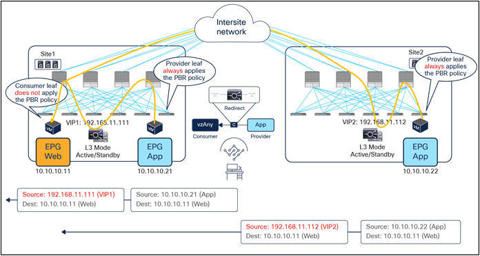
Load balancer without SNAT return traffic flows (east-west)
PBR to a firewall and a load balancer without SNAT (two nodes service graph)
This section covers a two-node firewall and load-balancer insertion use case for north-south and east-west communication. PBR is enabled for both directions (provider-to-consumer traffic and vice versa) to redirect traffic to the firewall, but PBR for the load balancer is only needed for the provider-to-consumer direction (since SNAT is not configured).
The same specific design considerations mentioned in the previous section for the load balancer only scenario are still valid here; thus, it is mandatory for the load balancer and the real servers to reside in the same site.
Though the example we present in Figure 63, below, has the firewall as the first service function and the load balancer without SNAT as the second, other service-function combinations or sequences are also possible, as, for example, those in the bulleted list below:
● The first service function is the firewall; the second is the load balancer with SNAT.
● The first service function is the load balancer with SNAT; the second is the firewall.
● The first service function is the load balancer without SNAT; the second is the firewall.
● The first service function is the firewall; the second is the IPS.
Note: As of Cisco ACI Release 6.0(5), a Multi-Site service graph can contain up to two service functions when defined in a Multi-Site template (that is, a template that can also be used to provision objects stretched across sites) and up to five service functions in case of autonomous templates. Also, as of Cisco ACI Release 6.0(5), a service graph with two or more nodes is not supported for any of the vzAny PBR use cases nor for the intersite transit routing PBR use case (L3Out-to-L3Out).
North-south traffic use case
Figure 63 shows a sample Cisco ACI network design for a two-node PBR service chain (a firewall and a load balancer without SNAT) applied to north-south-routed communication. A contract with an associated service graph with PBR is applied between the consumer L3Out EPG and the provider Web EPG. The endpoints in the Web EPG are real servers associated to the VIP on the load balancer. As always, the firewall and load balancer services are deployed as a distributed set of highly available service nodes deployed in each site.
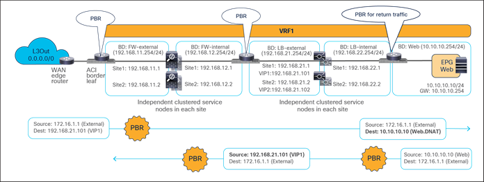
Sample design of a north-south firewall with PBR and a load balancer without SNAT
Figure 64 and Figure 65 illustrate an example of an inbound traffic flow between the external network and an internal Web EPG in an ACI Multi-Site deployment, where we have two connections: one is between the external network and the VIP (the frontend connection), and the other is between the load balancer and the real servers part of the Web EPG (the backend connection).
● Traffic originating from a client in the external network is destined to the VIPs (one in each site), thus the traffic is forwarded to the leaf nodes where the load balancers are connected as long as the VIPs are reachable. Notice how the VIPs could be locally deployed or reachable in a remote site.
● The PBR policy is applied on the load-balancer leaf nodes (since they represent the compute leaf nodes for the north-south traffic from the external network to the VIPs) and redirects the traffic to the first service function, which is the firewall. As previously discussed, the compute leaf nodes can always apply the policy because of the local static configuration of the IP prefix programmed under the L3Out EPG. Since the PBR policy is applied on the load-balancer leaf nodes, the consequence is that all inbound north-south flows will always be redirected to the firewall in the site where the load balancer with the destination VIP is located, independently from the specific L3Out where the inbound flow is received (as Figure 64 clearly highlights).
● The traffic is inspected by the firewalls; if allowed, it is then sent back to the fabric and reaches the VIPs residing on the load balancers.
● The load balancers change the destination IP to one of the real servers associated to the VIP and send the traffic back to the fabric (the load balancers do not change the source IP address since SNAT is not enabled).
● The traffic is forwarded to the real server destination, which must be deployed locally in each site.
Notice how redirection for inbound flows happens only to one service function (the firewall), since, from the firewall to the real server, all that is needed is just regular traffic forwarding. Also, the suboptimal inbound traffic shown in Figure 64 can be avoided by leveraging host-route advertisement to optimize the traffic path for ingress communication when the VIPs of the load balancer belong to a stretched BD.
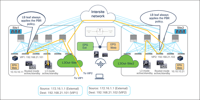
Firewall with PBR and load balancer without SNAT inbound traffic flows (external-client to VIP)
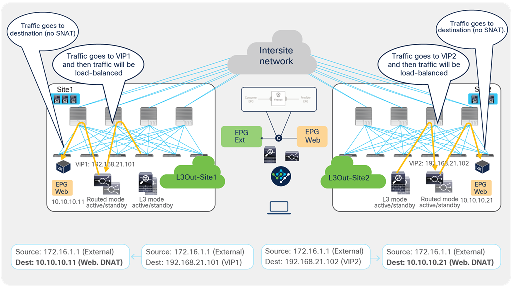
Firewall with PBR and load balancer without SNAT inbound traffic flows (VIP to real-servers)
As previously discussed, since the return traffic flows are destined to the original IP address of the external client, PBR is required to steer the flow through the load balancers.
● The PBR policy is associated to a contract between the Web EPG and the external client (north-south traffic), therefore it is applied on the compute leaf nodes where the Web endpoints are connected and redirects the traffic to the local load balancer. Once again, this is the reason the VIP and the server farm (Web EPG) must be deployed in the same fabric.
● Once the load balancers receive the traffic, they change the source IP to the VIP and forward the traffic back to the ACI fabric.
● At this point the second redirection associated to the contract between the Web EPG and the external client kicks in on the compute leaf nodes where the load balancers’ external interfaces are connected, and the traffic is forwarded to the firewalls.
● After the firewalls have applied their locally configured security policies, the traffic is forwarded back to the fabric so it can reach the external client through the local L3Out connections.
Therefore, in the outbound direction redirection must happen twice, first to the load-balancer service and then to the firewall service.
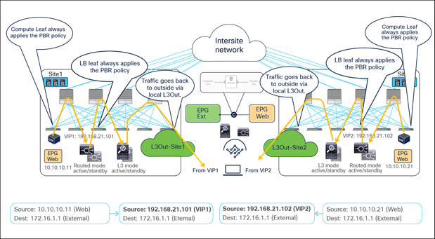
Firewall with PBR and load balancer without SNAT outbound traffic flows (north-south)
East-west traffic use case
Figure 67 shows a sample Cisco ACI network design for a two-node service chain, this time applied to the east-west traffic use case. This design is similar to the one for the north-south use case previously discussed. The contract with an associated two-nodes (firewall and load balancer) service graph with PBR is now applied between a consumer Web EPG and a provider App EPG. The endpoints in the App EPG are real servers associated to the VIP of the load balancer.
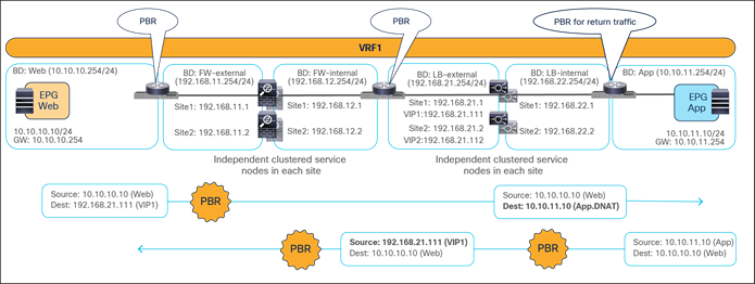
Sample design of an east-west firewall with PBR and a load balancer without SNAT
Figure 68 and Figure 69 illustrate an example of east-west communication between the consumer EPG Web and the provider EPG App in an ACI Multi-Site deployment where we have two connections: one is between a Web endpoint and the VIP (the frontend connection), and the other is between the load balancer and the real servers in the App EPG (the backend connection). As usual for all the scenarios not leveraging SNAT, the load balancer and the real servers must be deployed in the same site.
● The traffic originating from the consumer (Web) endpoint is destined to the VIP, so it reaches the leaf nodes where the load balancers are connected as long as the VIPs are reachable. In the example below, the same consumer EPG accesses two different VIPs (VIP1 and VIP2) defined in site1 and site2.
● The PBR policy is applied on the load-balancer leaf nodes and redirects traffic to the local firewalls (because they represent the provider leaf nodes for the traffic from the consumer to the VIP). As previously explained, this mandates the definition of an IP prefix under the consumer EPG identifying the endpoints part of that security group.
● The firewalls apply their security policies and then send the traffic back to the fabric toward the VIPs.
● The load balancers change the destination IPs to one of the real servers associated to the VIPs and forward the traffic to the destinations. In this example, the load balancers do not perform SNAT and hence do not alter the source IP address.
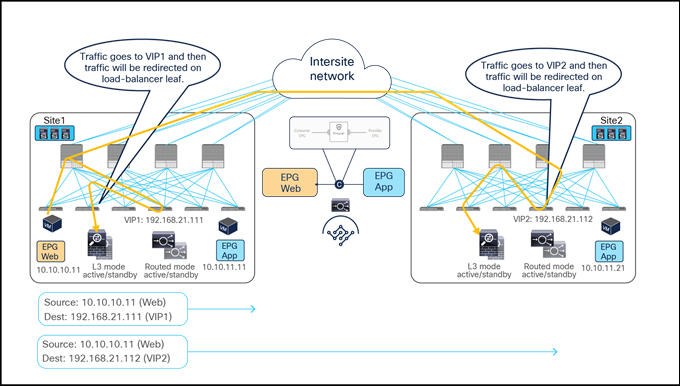
Firewall with PBR and load balancer without SNAT east-west traffic flows (client to VIPs)
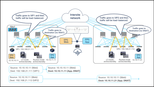
Firewall with PBR and load balancer without SNAT east-west traffic flows (VIP to real-server)
Because the return traffic is destined to the original source IP (the Web endpoint), PBR is required to steer the return traffic to the load balancers.
● The provider endpoints (real servers) originate traffic destined to the consumer endpoint. The PBR policy gets applied on the leaf nodes where the real servers are connected, because they represent the provider leaf nodes for the east-west communication between the App (provider) endpoint and the Web (consumer) endpoint. The traffic gets steered to the load balancers, which must be located in the same site.
● The load balancers change the source IP to match the VIP address and send the traffic back to the ACI fabric.
● Another PBR policy is then applied on the load-balancer leaf nodes to redirect the traffic to the firewalls.
● The firewalls perform their security policy enforcement and send the traffic back to the fabric.
● The traffic is forwarded to the consumer (Web) endpoint, which can be located in the local site or in a remote site (as highlighted in Figure 71).
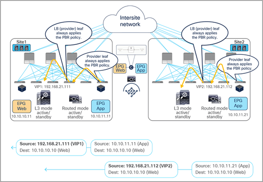
Firewall with PBR and load balancer without SNAT east-west traffic flows (real servers to firewalls)
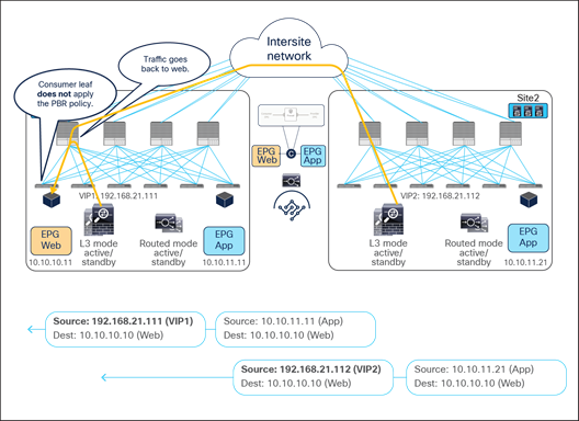
Firewall with PBR and load balancer without SNAT east-west traffic flows (firewalls to client)
This section covers several examples of designs that leverage combinations of the supported use cases explained in the previous sections.
Example 1: Insert firewall for most (but not all) inter-EPG traffic in a VRF.
The figure below illustrates a sample design that has the following requirements:
● Application-centric (Multiple EPGs are configured as part of the same BD and IP subnet.)
● All of inter-EPG traffic needs to be inspected by a firewall except specific EPG-to-EPG combinations (in this example, App-to-DB traffic needs to be permitted at the fabric level without being redirected to the firewall).
● Intra-EPG communication should happen freely.
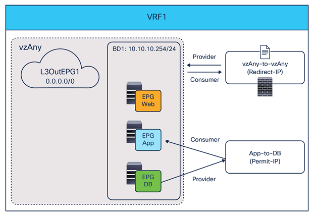
Sample design 1: vzAny-to-vzAny PBR with specific EPGs-to-EPGs permit contract to bypass firewall
By using a vzAny-to-vzAny contract (with a “permit IP” filter) associated to a service graph with PBR, all inter-EPG traffic in the VRF is redirected to the firewall. Intra-EPG traffic is always permitted because the intra-EPG implicit permit rule (priority 3) wins over the vzAny-to-vzAny redirect rules (priority 17).
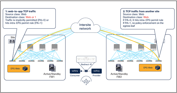
Intra-EPG permit rule wins over vzAny-to-vzAny rule
By adding a specific EPG-to-EPG contract with a permit action, the redirection to the firewall can be bypassed for this communication because the specific EPG-to-EPG contract rules (priority 7 or 9) wins over the vzAny-to-vzAny contract redirect rules (priority 17).
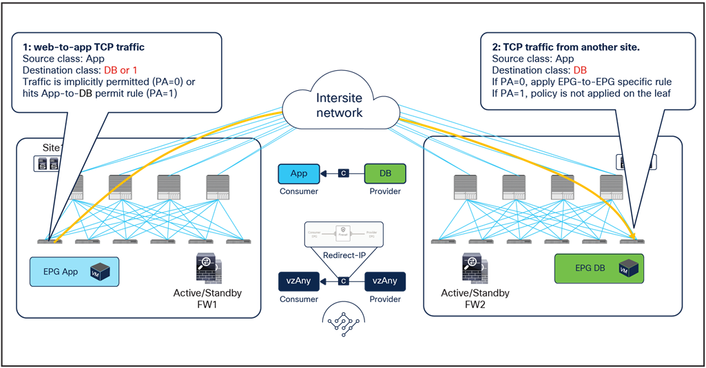
Specific EPG-to-EPG rule wins over vzAny-to-vzAny rule
In addition to this, by using specific filters for the vzAny-to-vzAny contract with PBR, other inter-EPG traffic can be denied or just permitted in the VRF. For example, if vzAny-to-vzAny contract with PBR uses a more specific “permit TCP” filter instead of a “permit IP” filter, UDP traffic between EPG Web and EPG App will be denied because there is no permit or redirect rule applicable to that type of traffic (Figure 75).
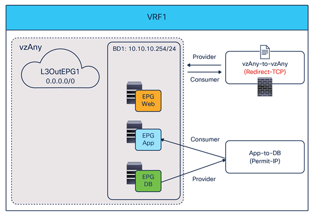
Use specific filter to redirect specific vzAny-to-vzAny traffic
Example 2: Use different firewalls for north-south and east-west traffic
Example 1, above, uses the same one-arm firewall for both north-south (L3Out-to-EPGs) and east-west (EPG-to-EPG) traffic. If the requirement was, instead, to use a different two-arm firewall for north-south traffic (often this need is driven by security reasons), it is possible to introduce a separate EPGs-to-L3Out contract with PBR that can coexist with the vzAny-to-vzAny contract with PBR used in Example 1 (Figure 76).
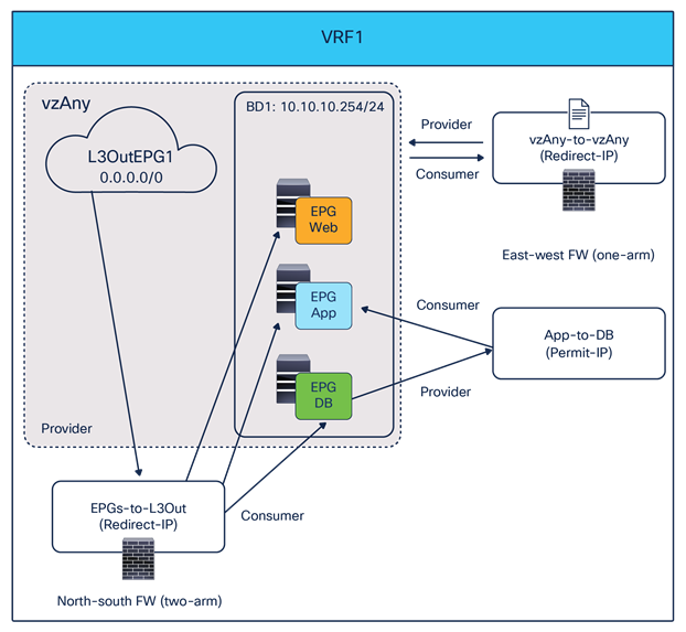
Use a different two-arm firewall for north-south traffic
Because, in the intra-VRF scenario, the PBR policy is always applied on the non-border leaf for an EPGs-to-L3Out contract for north-south traffic, there is no need to specify an IP prefix under the EPG. Thus, EPGs such as Web, App, and DB can be part of the same IP subnet. Since the EPGs-to-L3Out contract’s rule (priority 7 or 9) wins over the vzAny-to-vAny rule (priority 17), north-south traffic will always be redirected to the two-arm firewall, whereas east-west traffic will still use the other one-arm firewall (with the exception of the communication between App and DB permitted by a specific contract).
Configuration after Cisco Nexus Dashboard Orchestrator Release 4.2(1)
This section describes the general service chaining configuration by using an L4-L7 configuration workflow introduced in Cisco Nexus Dashboard Orchestrator (NDO) Release 4.2(1). For service graph configuration steps, please refer to Configurations prior to Cisco Nexus Dashboard Orchestrator Release 4.2(1).
Note: This document shows GUI screenshots taken from Cisco ACI Release 6.0(4c) and NDO release 4.2(3e). Thus, the GUI “look and feel” in this document might be slightly different from your specific ACI or NDO GUI.
Some objects must be created on each ACI domain and on the NDO before going into the service-chaining configuration. This section does not cover how to configure interface policies, domains, tenants, VRFs, BDs, EPGs, L3Out, and contracts. The assumption is that these items are already configured.
For more information on the use of NDO to deploy configurations and/or objects stretched across sites, please refer to the configuration guide below: https://www.cisco.com/c/en/us/support/cloud-systems-management/multi-site-orchestrator/products-installation-and-configuration-guides-list.html.
For the deployment of a service chaining specific to an ACI Multi-Site architecture, there are three configuration steps that must be performed on NDO. The sections that follow provide more detailed information on each of the configuration steps listed below:
● Create a tenant policy template for defining an IP-SLA monitoring policy
● Create a service device template for defining the service device(s) to which redirect the traffic
● Configure a service chaining in a contract
Note: If a contract has a stretched consumer and provider objects, such as vzAny of a stretched VRF across sites or an EPG or External EPG stretched across site, PBR configuration must be also done through NDO.
Create a tenant policy template for IP-SLA monitoring policy
This step is to create an IP-SLA monitoring policy in a tenant policy template associated to a specific tenant and mapped to all the sites where the tenant is deployed. IP-SLA tracking is used to check availability information of each PBR destination and to detect each PBR destination MAC dynamically. IP-SLA tracking is mandatory for vzAny-to-vzAny, vzAny-to-EPG, vzAny-to-L3Out and L3Out-to-L3Out contract with PBR use cases. Although it’s not mandatory for other use cases, it is generally recommended to enable IP-SLA tracking for faster failure detection. In this example, we are going to create an IP-SLA policy using Internet Control Message Protocol (ICMP) to monitor the status of the service device(s).
The first step is to create a tenant policy template. The location is at Configure > Tenant Templates > Tenant Policies > Create Tenant Policy Template.
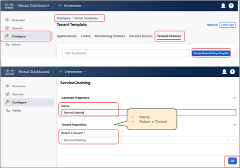
In the created tenant policy template, associate the template to the sites and save the template.
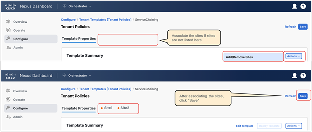
Then, Create Object > IPSLA Monitoring Policy, and specify SLA Type, SLA Frequency, Detect Multiplier, and other options if needed.
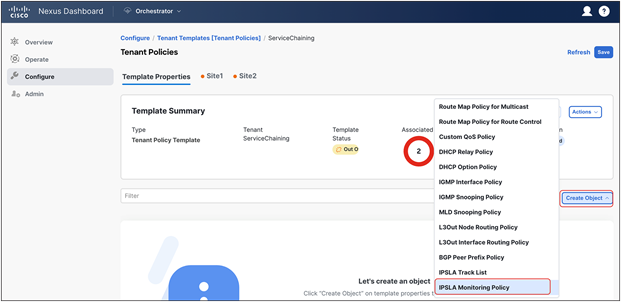
Select “IPSLA Monitoring Policy”
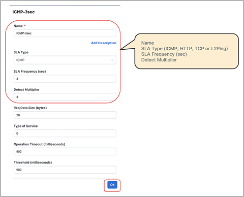
Create IPSLA monitoring policy
Finally, deploy the tenant policy template to the sites.
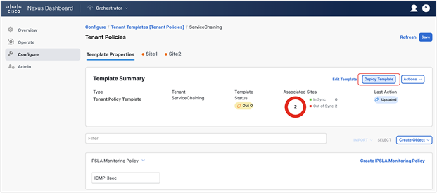
Deploy the template to the sites
If the deployment is successfully done, the IP-SLA policy is created in the tenant on each APIC domain. The location on APIC is at Tenant > Policies > Protocol > IP SLA > IP SLA Monitoring Policies.
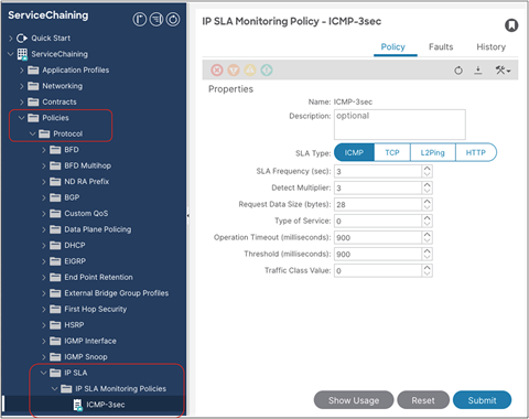
Verify the configuration on APIC (IP-SLA monitoring policy)
Create a service device template
Service device templates allow you to define the service nodes (L4-L7 devices and PBR policies) associated to a given tenant in one or more sites. A service device template has a template-level configuration and a site-level configuration as follows:
● Template-level configuration:
◦ Device type: FW/LB/Others
◦ Device mode: L3/L2/L1 (routed/transparent/inline)
◦ Number of interfaces of the service device: one-arm, two-arm, or more
◦ BD or L3Out for each service-device interface
◦ Redirection (PBR) enabled or disabled for each service-device interface
● Site-level configuration:
◦ Domain type: physical or VMM domain
◦ Path (physical domain) or VM (VMM domain) information
Note: PBR to a destination in another site because of local PBR destination failure is NOT supported. Thus, it is strongly recommended to deploy the local service nodes in a highly available way.
The first step is to create a service device template. The location is Configure > Tenant Templates > Service Device > Create Service Device Template.
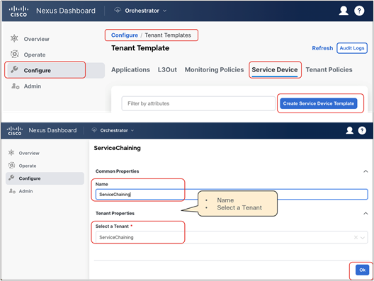
Create a service device template
In the created service device template, select “Add/Remove Sites” to associate the template to the sites, and save the template.
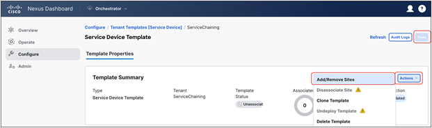
Associate the template to the sites
Next, you are going to create a service device in the template. The location is at Create Object > Service Device Cluster. After you complete template-level configurations for the service device, you are going to configure site-level configurations.
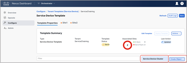
Create a service-device cluster
In this document, we are going to configure the following service devices illustrated in the figure below:
● L3 firewall with two interfaces
● L3 load balancer with two interfaces
Depending on the service-device insertion use case, you are going to redirect traffic to only one or to both interfaces. Although some use cases only support one-arm mode insertion, the service device can have more than one interface.
Note: that the BDs where the service-devices’ interfaces are connected need to be selected as part of the service device template configuration. Thus, please ensure you have already created those BDs in the tenant by using specific application templates.
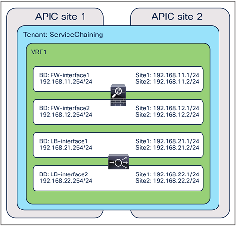
Example of a service-device configuration
L3 firewall configuration example
At the template level for a service device template configuration, you first need to select a device type and device mode. Some options are grayed out if the options are not applicable based on your selection.
The next step is to select the connectivity mode. If one-arm is selected, you are going to select a bridge domain or an L3Out for one interface. If redirect is enabled, the IP-SLA policy configuration option is shown in the UI. Though not mandatory, it is generally recommended to specify an IP-SLA policy that enables IP-SLA tracking for the PBR destinations for the interface.
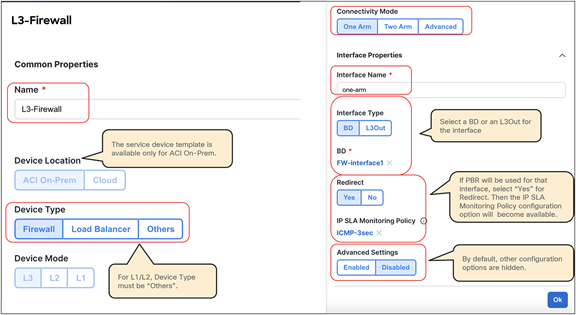
Example of an interface configuration (one-arm)
If you select two-arm, the UI shows the table that has the list of interfaces. You need to repeat the configuration for each interface by clicking the pencil icon for each interface. If you have more than two interfaces, select Advanced and continue configuring the third interface, and so on.
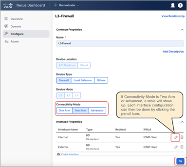
Example of an interface configuration (two-arm)
After the template-level configuration is completed, the next step is to configure site-level configurations. Select one of the sites and click the service device that you just created.
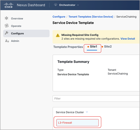
Select a physical domain or a VMM domain. Depending on the domain, the required configuration options will be different.
In the case of VMM domain, by default a VLAN will be allocated dynamically from the VLAN pool used in the VMM domain. Thus, a VLAN ID is not a mandatory configuration, but you can specify a VLAN if the VLAN pool has a static VLAN range. If Link Aggregation Control Protocol (LACP) is used for virtual switch to upstream switch connectivity, select Enhanced LAG Option. Then select a VM and its virtual Network Interface Card (NIC).
If you have more than one interface, repeat the step for other interfaces. The figure below shows a two-arm-mode firewall example.
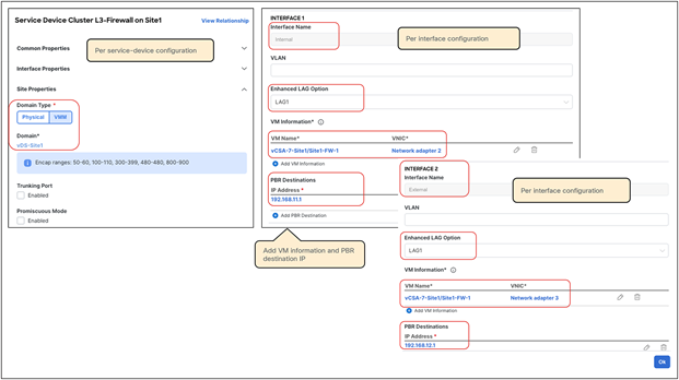
Example of a site-level configuration (VMM domain)
If you have more than one VM, repeat this step for other VMs.
● Figure 91 shows an example of an active-standby HA pair: two VMs with one PBR destination IP per PBR policy (two-arm deployment). A single IP identifies the HA pair on each of the defined interfaces, and, as a consequence, a health group is automatically created.
● Figure 92 shows, instead, the deployment of independent service nodes: two VMs with two PBR destination IPs per PBR policy (in this example, also a two-arm deployment). In this case, a specific TAG is required for health-group configuration and must be associated to each PBR destination to group the PBR destination IP for consumer-to-provider direction and the PBR destination IP for provider-to-consumer direction from multiple PBR destination IP addresses.
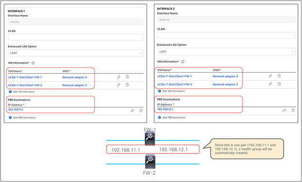
Example of a site-level configuration for an active/standby HA pair that is part of a VMM domain
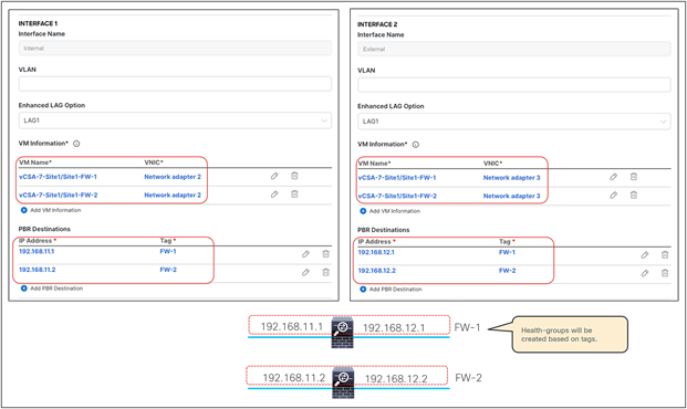
Example of a site-level configuration for independent service nodes that are part of a VMM domain
In the case of a physical domain, select a path and a VLAN ID for each interface similar to an EPG with static path bindings. Figure 93 is an example of a two-arm active/standby HA example: two VMs with one PBR destination IP per PBR policy.
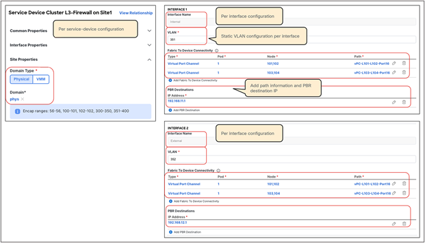
Example of a site-level configuration (physical domain)
After the site-level configuration is done for a site, repeat it for the remaining site(s) and then deploy the template.
If deployment is successfully done, the L4-L7 Device and the PBR policy are created in the tenant in each APIC domain. The locations on APIC are at Tenant > Services > L4-L7 > Devices for the L4-L7 Devices and at Tenant > Policies > Protocol > L4-L7 Policy-Based Redirect for the PBR policy.
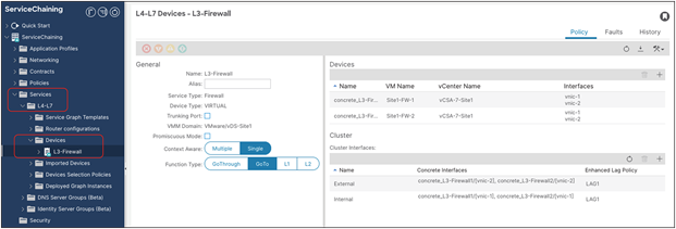
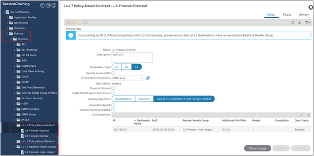
Verify the configurations on APIC (L4-L7 Device and PBR policy
Advanced options
If “Advanced Option” is enabled, the UI shows additional configuration items, such as load-balancing hashing options, etc. This approach is taken to show the minimum configuration options (usually the most commonly used), unless advanced configurations are required.
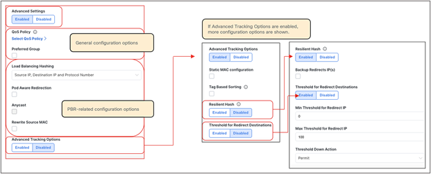
Advanced configuration options (template-level)
Depending on the “Advanced” settings in the template-level configuration, you might require additional configurations in the site-level configuration. For example, if “Pod Aware Redirection” is enabled, you need to configure a pod ID for each PBR destination IP.
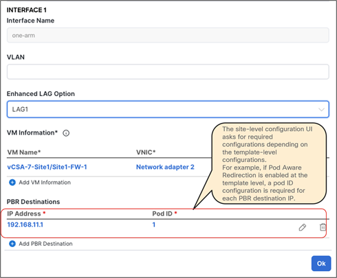
Advanced configuration options (site-level)
L3 load-balancer configuration example
Because the configuration steps and options required for the load balancer are almost identical to those for the firewall example presented in the previous subsection, this subsection shows only the configurations required for a two-arm load balancer deployed as a virtual machine that is part of a VMM domain.
At the template-level of the service device template configuration, you first need to select a device type and device mode. Some options are grayed out if the options are not applicable based on your selection. The figure below shows an example of a two-arm load balancer where PBR is enabled on the internal interface only. If redirect is not enabled, there is no need to select an IP-SLA policy.
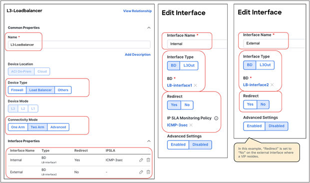
Example of a load-balancer configuration (two-arm, template-level)
At the site level configuration, select a physical domain or a VMM domain. Depending on the selected domain, the required configuration options will be different. If PBR is not enabled on the interface at the template level, there is no need to configure the PBR destination’s IP information for that interface.
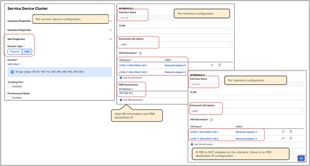
Example of a load-balancer configuration (two-arm, site-level with VMM domain)
After the site-level configuration is done for a site, repeat it for the remaining site(s) and then deploy the template.
If the deployment is successfully done, the L4-L7 Device and the PBR policy are created in each APIC domain for the specified tenant. The locations on APIC where to find the provisioned objects are at Tenant > Services > L4-L7 > Devices for the L4-L7 Device and at Tenant > Policies > Protocol > L4-L7 Policy-Based Redirect for the PBR policy.
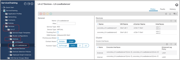
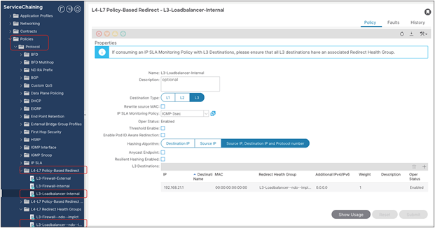
Verify the configuration on APIC (L4-L7 Device and PBR policy)
This step differs depending on use cases. This section will cover the following use cases:
● EPG-to-EPG contract with PBR
● L3Out-to-EPG contract with PBR
● vzAny-to-vzAny contract with PBR (The configuration steps are the same than for the vzAny-to-L3Out and L3Out-to-L3Out contract with PBR use cases.)
● vzAny-to-EPG contract with PBR (firewall and load balancer)
Example 1: EPG-to-EPG contract with PBR
This subsection covers a configuration step for EPG-to-EPG for firewall and load-balancer insertion. One node and multinode service chaining, such as inserting a firewall and then a load balancer, are supported for an EPG-to-EPG contract with PBR. PBR can be enabled on both directions or either one of the directions. Though the figure below illustrates multiple intra-VRF examples, inter-VRF is also supported. For inter-VRF, the service BDs must be in either the consumer or the provider VRF.
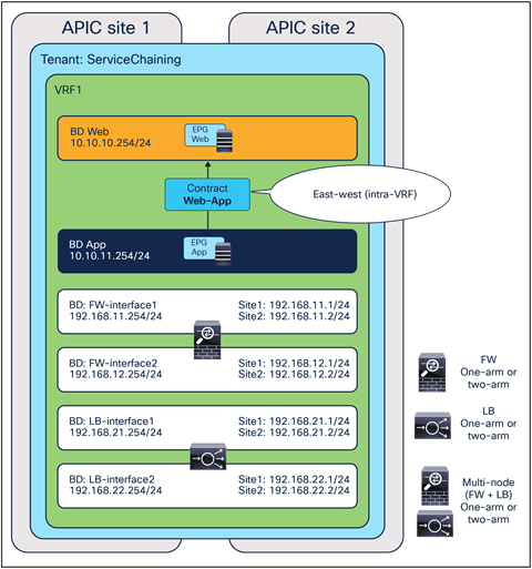
EPG-to-EPG contract with PBR (intra-VRF)
This subsection shows the following configuration examples:
● Bidirectional PBR for firewall insertion
● Uni-directional PBR for load-balancer insertion (PBR is enabled for the provider-to-consumer direction.)
Prerequisite
In the case of EPG-to-EPG contracts with PBR, one or more IP prefixes must be configured under each consumer EPG. Because this IP prefix is not intended to be used for network connectivity (but only to derive the class-ID information for the consumer EPG), “No Default SVI Gateway” needs to be checked.
Note: Starting from Cisco ACI Release 6.0(3), it is also supported to specify /32 IPv4 prefixes (or /128 IPv6 prefixes) under the consumer EPGs.
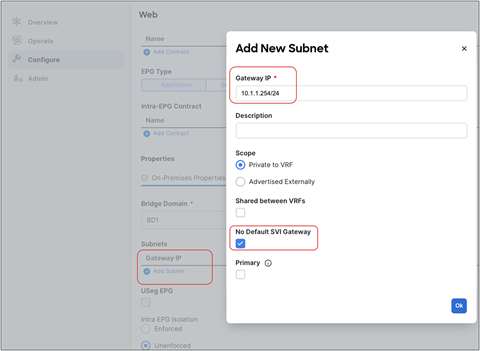
Consumer EPG subnet configuration
Configure service chaining
Service insertion is configured by associating one or more service devices with a contract. This is provisioned from Configure > Tenant Template > Applications. Select your template and then the contract.
At the bottom of the contract’s configuration, ensure service chaining is selected. It shows the list of the consumers and the providers of the contract (if already configured). By clicking the “+” icon, you can add one or more service devices to create a service chaining between the consumers and the providers.
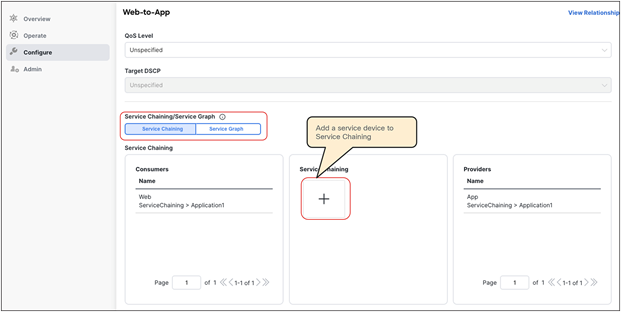
Select device type, device, and interfaces. The figures below show the device settings for the following:
● One-arm mode firewall with PBR for both directions
● Two-arm mode firewall with PBR for both directions
● One-arm mode load balancer with PBR for the provider-to-consumer direction
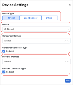
One-arm mode firewall with PBR for both directions
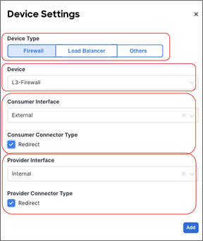
Two-arm mode firewall with PBR for both directions
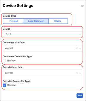
Two-arm mode load balancer with PBR for the provider-to-consumer direction
If you have multiple nodes, add another service device and repeat the same steps. The figure below shows an example of a two-node service-chaining, in this case for firewall and load balancer.
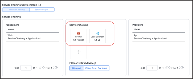
Two node service chaining example
If the deployment is successfully done, the service graph, device-selection policy, and deployed graph Instance are created for the tenant on each APIC domain. This can be verified on APIC at Tenant > Services > L4-L7 > Device Selection Policies and Deployed Graph Instances.
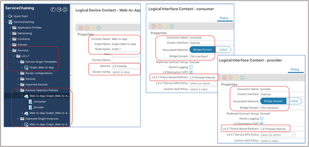
Verify the configuration on APIC (Device Selection Policy and Deployed Graph Instance)
Example 2: L3Out-to-EPG contract PBR
This subsection covers a configuration step for L3Out-to-EPG for firewall and load-balancer insertion. One node and multinode service chaining, such as inserting a firewall and then a load balancer, are supported for an L3Out-to-EPG contract with PBR. PBR can be enabled on both directions or either one of the directions. Though the figure below illustrates multiple intra-VRF examples, inter-VRF is also supported. For inter-VRF, the external EPG must be the provider, and the service BDs must be in either the consumer or the provider VRF.
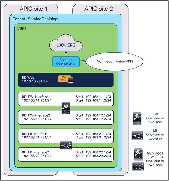
L3Out-to-EPG contract with PBR (intra-VRF)
Because the configuration steps and options required for L3Out-to-EPG contract with PBR are almost identical to the EPG-to-EPG contract with PBR example presented in the previous subsection, this subsection only shows the configuration required for two-arm firewall with bidirectional PBR.
Configure service chaining
Service insertion is configured by associating one or more service devices with a contract. This is provisioned from Configure > Tenant Template > Applications. Select your template and then the contract.
At the bottom of the contract’s configuration, ensure that service chaining is selected. It shows the list of the consumers and the providers of the contract (if already configured). By clicking the “+” icon, you can add one or more service devices to create a service chaining between the consumers and the providers.
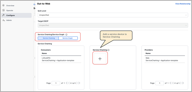
Select device type, device, and interfaces. The figure below shows an example of a two-arm mode firewall with PBR for both directions. For other examples, please see the previous subsection for an EPG-to-EPG contract with PBR.
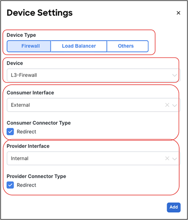
Confirm that the service device is added to the service chaining in the contract, and then deploy the template to the sites.
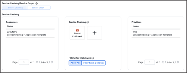
Confirm service chaining configuration
If the deployment is successfully done, the service graph, device-selection policy, and deployed graph Instance are created for the tenant on each APIC domain. This can be verified on APIC at Tenant > Services > L4-L7 > Device Selection Policies and Deployed Graph Instances.
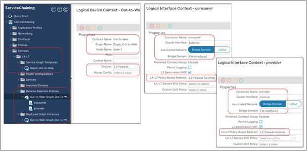
Verify the configuration on APIC (Device Selection Policy and Deployed Graph Instance)
Example 3: vzAny-to-vzAny contract with PBR
This subsection covers a configuration step for vzAny-to-vzAny, which is applicable to vzAny-to-L3Out and L3Out-to-L3Out contracts with PBR as well. Besides contract-relationship configuration, the service-chaining configuration for these use cases are identical: one-arm one-node firewall insertion with PBR enabled on both directions. vzAny-to-vzAny and vzAny-to-L3Out contracts with PBR support intra-VRF contracts only, whereas an L3Out-to-L3Out contract with PBR supports both intra- and inter-VRF contracts. For inter-VRF, the service BD must be in either the consumer or the provider VRF.
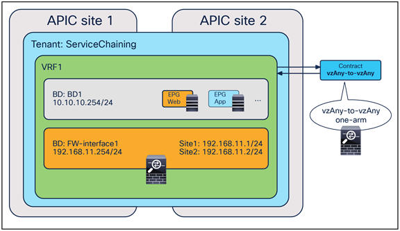
vzAny-to-vzAny contract with PBR
Prerequisites
In the case of vzAny-to-vzAny, vzAny-to-EPG, vzAny-to-L3Out, and L3Out-to-L3Out contracts with PBR, the “L3 Multicast” and “Site-aware Policy Enforcement Mode” knobs must be enabled (Figure 114). For L3 multicast, the provisioning of a Rendezvous Point (RP) is not required. The reason “L3 Multicast” is required is explained at Why do “Site-aware Policy Enforcement Mode” and “L3 Multicast” need to be enabled on the VRF for vzAny PBR? in FAQ section.
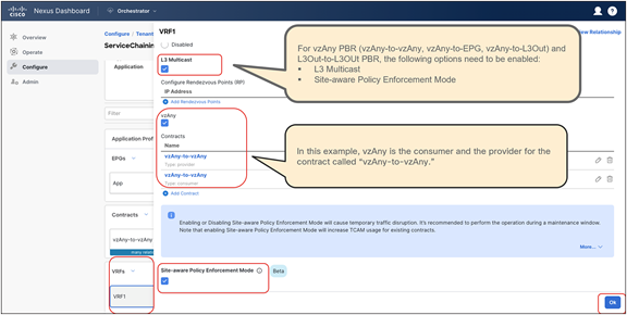
“L3 Multicast” and “Site-aware Policy Enforcement Mode” on VRF
The consumer, provider, and service BDs must be set to “Hardware Proxy” mode (Figure 115).
This is because when a BD is in “Flood” mode if the destination MAC is unknown, packets will hit an implicit permit rule (any-to-BD_class_ID) and won’t be redirected. Please see Cisco ACI contract guide that has implicit rule list.
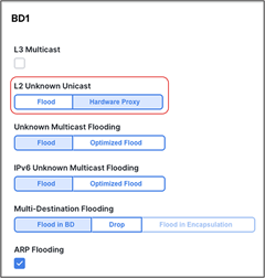
BDs must be set to “Hardware Proxy Mode.”
Configure service chaining
Service insertion is configured by associating one or more service devices with a contract. This is provisioned from Configure > Tenant Template > Applications. Select your template and then the contract.
At the bottom of the contract’s configuration, ensure that “Service Chaining” is selected. It shows the list of the consumers and the providers of the contract (if already configured). By clicking the “+” icon, you can add one or more service devices to create a service chaining between the consumers and the providers.
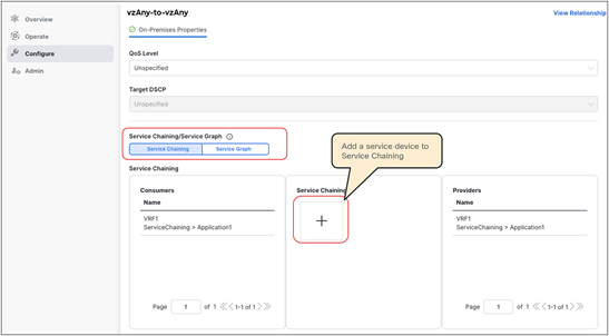
Select device type, device, and interfaces. In the case of vzAny-to-vzAny, vzAny-to-L3Out, and L3Out-to-L3Out contracts with PBR, you must select the same interface and enable the redirect flag for both the consumer and the provider interfaces, because the use cases are supported only with one-arm bidirectional PBR. If the service device was defined with only one interface, it would be automatically selected.

Confirm that the service device is added to the service chaining in the contract, and then deploy the template to the sites.
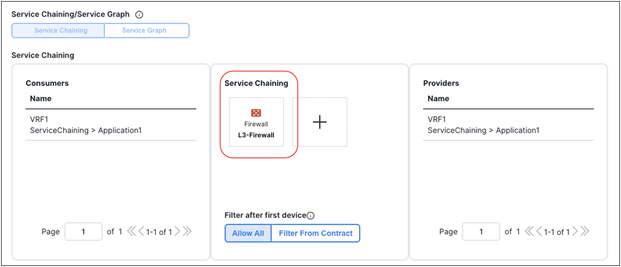
Confirm cervices chaining configuration
If the deployment is successfully done, the service graph, device-selection policy, and deployed graph Instance are created for the tenant on each APIC domain. This can be verified on APIC at Tenant > Services > L4-L7 > Device Selection Policies and Deployed Graph Instances.
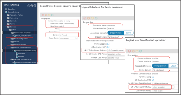
Verify the configuration on APIC (Device Selection Policy and Deployed Graph Instance)
Example 4: vzAny-to-EPG PBR
This subsection covers the configuration steps required for the vzAny-to-EPG PBR use case, which is supported for both firewall and load-balancer insertion. For both use cases, and prior to ACI Release 6.1(3), only one-arm and one-node design is supported. PBR can be enabled on both directions or either one of the directions. This subsection shows the following configurations:
● Bidirectional PBR for firewall insertion
● Unidirectional PBR for load-balancer insertion (PBR is required only for the provider to consumer direction).
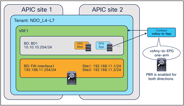
vzAny-to-EPG contract with PBR (firewall)
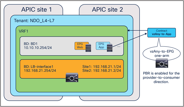
vzAny-to-EPG contract with PBR (load balancer)
Prerequisites
Just as in the case for vzAny-to-vzAny, vzAny-to-L3Out, and L3Out-to-L3Out contracts with PBR, the “L3 Multicast” and “Site-aware Policy Enforcement Mode” flags must be enabled (Figure 114). For L3 multicast, the configuration of Rendezvous Points (RPs) is not required.
As previously shown, the provider and service BDs must be configured in “Hardware Proxy” mode (Figure 115).
Configure service chaining
Service insertion is configured by associating one or more service devices with a contract. This is provisioned from Configure > Tenant Template > Applications. Select your template and then the contract.
At the bottom of the contract’s configuration, ensure that service chaining is selected. It shows the list of the consumers and the providers of the contract (if already configured). By clicking the “+” icon, you can add one or more service devices to create a service chaining between the consumers and the providers.
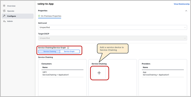
Select device type, device, and interfaces. Prior to ACI Release 6.1(3), for a vzAny-to-EPG contract with PBR you must select the same interface for both the consumer and the provider interfaces, because the use case is supported only with one-arm devices. PBR can be enabled for traffic in both directions (inserting a firewall) or in one direction only (inserting a load balancer).
The figures below show the device settings for the following:
● One-arm mode firewall with PBR for both directions.
● One-arm mode load balancer with PBR for the provider-to-consumer direction.
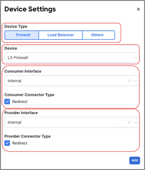
One-arm firewall insertion (bidirectional PBR)
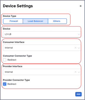
One-arm load-balancer insertion (unidirectional PBR)
Confirm that the service device is added to the service chaining in the contract, and then deploy the template to the sites.
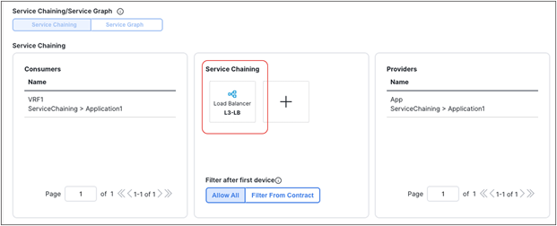
Confirm service chaining configuration (load balancer)
If the deployment is successfully done, the service graph, device selection policy, and deployed graph Instance are created for the tenant on each APIC domain. This can be verified on APIC at Tenant > Services > L4-L7 > Device Selection Policies and Deployed Graph Instances.
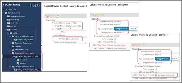
Verify the configuration on APIC (Device Selection Policy and Deployed Graph Instance)
GUI and CLI output example for verification
The following steps are typical for troubleshooting. This section explains how to verify steps 2 and 3, which are specific to a service graph. This document does not cover general Cisco ACI endpoint learning or forwarding troubleshooting steps. For more information about Cisco ACI troubleshooting, refer to the following link: https://www.cisco.com/c/dam/en/us/td/docs/switches/datacenter/aci/apic/sw/4-x/troubleshooting/Cisco_TroubleshootingApplicationCentricInfrastructureSecondEdition.pdf.
1. Check if the communication between EPGs can be established without attaching the service graph with PBR to the contract:
◦ Consumer and provider endpoints are learned.
◦ Consumer and provider endpoints can communicate within the same site and across sites.
2. Verify the service-graph deployment (on each APIC):
◦ Deployed graph Instances have no faults.
◦ VLANs and class IDs for service nodes are deployed.
◦ Service -node endpoints are learned.
3. Check that the traffic is successfully redirected:
◦ Capture the traffic on the service node.
◦ Check that the policy is properly programmed on the leaf nodes.
4. Check that the incoming traffic arrives on the consumer and provider endpoints.
Check that a service graph is deployed
Deployed graph instances
After a service graph is successfully applied, you can see the deployed graph instance for each contract with a service graph (Figure 127). If a service graph instantiation fails, you will see faults in the deployed graph instance.
The location is Tenant > Services > L4-L7 > Deployed Graph instances.
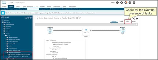
Check that the graph instance is deployed on APIC
VLANs and class IDs for service node
If you see a fault, it’s most likely because there is something wrong with the APIC configuration. For example, the encap VLAN is not available in the domain used for the L4–L7 device.
Once the service graph is successfully deployed without any fault in the deployed graph instances, EPGs and BDs for service node get created. Figure 128 and Figure 129 show where to find the class IDs for the service-node interfaces (Service EPGs). In this example, the site1 FW-external class ID is 16388 and the site1 FW-internal class ID is 49156.
The location is Tenant > Services > L4-L7 > Deployed Graph instances > Function Nodes.
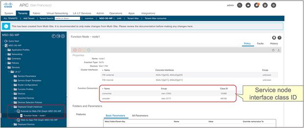
Service-node interface class ID (external-to-web SG)
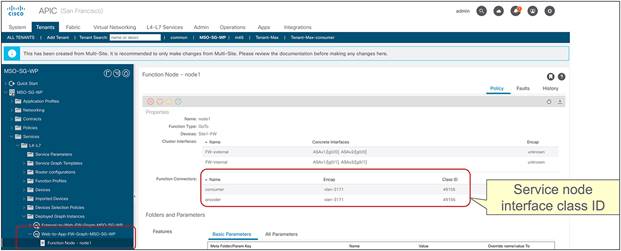
Service-node interface class ID (web-to-app SG)
These VLANs are deployed on the service leaf node where the service nodes are connected. VLAN and endpoint learning status can be checked by using “show VxLAN extended” and ‘show endpoint” on the service leaf node CLI. If you don’t see the IPs of service nodes learned as endpoints in the ACI fabric, most likely it’s a problem of connectivity or a configuration issue between the service leaf and the service node. Please check the following statuses that might have something wrong:
● Interface status on leaf interfaces connected to the service node.
● The leaf interface path and VLAN encap.
● The service node VLAN and IP address.
● The intermediate switch VLAN configuration if you have it between the service leaf node and the service node.
Check if the traffic is redirected
Capture the traffic on the service node
If end-to-end traffic stops working once you enable PBR, even though the service-node endpoints are learned in the ACI fabric, the next troubleshooting step is to check if traffic is redirected and where the traffic is dropped.
To verify whether traffic is actually redirected to the service node, you can enable capture on the PBR destination. Figure 130 shows an example of where you should see the traffic redirected. In this example, EPG Web to EPG App (EPG-to-EPG) contract with PBR is configured and 10.10.11.11 in site1 Web EPG tries to access 10.10.12.12 in site2 App EPG. Because the endpoint 10.10.12.12 is in the provider EPG, the PBR policy is applied in site2, thus traffic should be seen on the PBR destination in site2.
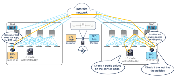
If you see that consumer-to-provider traffic is received on the service node but not on the provider endpoint, please check the following, which are common mistakes:
● Service node routing table reaches the provider subnet (The service node must be able to reach the provider and consumer subnets).
● Service node security policy such as ACL permits the traffic.
Check policies on leaf nodes
If you do not see the traffic being received by the service node, you may need to take a look at the leaf nodes to see if policies are programmed on the switch nodes to permit or redirect the traffic.
Note: The policies are programmed based on EPG deployment status on the leaf. The show-command output in this section uses the leaf that has consumer EPG, provider EPG, and EPGs for the service node.
Example1: EPG-to-EPG contract with PBR
Figure 131 and Figure 132 show the zoning-rule status before and after a service graph deployment in site1. In this example, the VRF scope ID is 3047427, the consumer EPG class ID is 32771, and the provider EPG class ID is 49154.
Before deploying the service graph, a leaf node has four permit zoning-rules. Two are for a north-south contract between the L3Out EPG and the Web EPG. The others are for an east-west contract between the Web EPG and the App EPG.
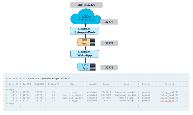
EPG class IDs and zoning-rules (before service-graph deployment)
Table 3. Permit rules without a service graph
| Source class ID |
Destination class ID |
Action |
| 32773 (L3Out EPG) |
32771 (Web EPG) |
Permit |
| 32271 (Web EPG) |
32773 (L3Out EPG) |
Permit |
| 32271 (Web EPG) |
32772 (App EPG) |
Permit |
| 32772 (App EPG) |
32271 (Web EPG) |
Permit |
Once the service graph is deployed, the zoning-rules get updated and the service node’s class IDs are inserted based on the service graph configuration. Zoning-rules highlighted in red are related to the north-south contract and the ones highlighted in blue are related to the east-west contract.
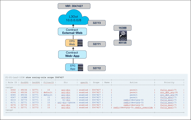
EPG class IDs and zoning-rules (after service-graph deployment)
Table 4. Permit and redirect rules with service graph
| Source class ID |
Destination class ID |
Action |
| 32773 (L3Out EPG) |
32771 (Web EPG) |
Redirect to destgrp-6 (FW-external) |
| 49156 (FW-internal) |
32271 (Web EPG) |
Permit |
| 32271 (Web EPG) |
32773 (L3Out EPG) |
Redirect to destgrp-5 (FW-internal) |
| 16388 (FW-external) |
32773 (L3Out EPG) |
Permit |
| 32271 (Web EPG) |
32772 (App EPG) |
Redirect to destgrp-5 (FW-internal) with redir_override |
| 49156 (FW-internal) |
32772 (App EPG) |
Permit |
| 32772 (App EPG) |
32271 (Web EPG) |
Redirect to destgrp-5 (FW-internal) |
| 49156 (FW-internal) |
32271 (Web EPG) |
Permit |
Note: The zoning-rule for EPG-to-EPG contract with PBR is created with action “redir_override”: this is required in the specific PBR deployment with Cisco ACI Multi-Site. With this action, the hardware creates two entries to take different actions depending on whether the destination (provider) is in the local site or not. If the destination is in the local site, the PBR policy is applied. If the destination is not in the local site, the traffic is just permitted so that the redirection can instead happen on the leaf in the site where the provider endpoint resides. That’s how to get a provider leaf to always apply PBR policy.
Important Note: In the case of EPG-to-EPG contract with PBR, it is critical to ensure that it is always possible to clearly identify a consumer and a provider side in zoning-rules for each given contract relationship between EPGs.
This means that the same EPG should never consume and provide the same contract and the definition of different contracts may be needed depending on the specific deployment scenario.
Also, if two different contracts were applied between the same pair of EPGs (so to be able to differentiate the provider and consumer EPG for each of them), it is critical to ensure that the zoning-rules created by those two contracts don’t have overlapping rules with same contract and filter priorities. Defining zoning-rules with the same priority that identify the same type of traffic could lead to a not deterministic forwarding behavior (creating asymmetric traffic through different firewalls). As a typical example, it would not work to create two contracts both using a “permit any” rule to redirect all the traffic. If one contract is “permit any” and the other contract is “permit ICMP only”, the zoning-rules created by the contract with “permit ICMP only” have higher priority. The table and figure below illustrate this example. In this case, ICMP traffic between Web and App EPGs is always redirected on the leaf where an endpoint in the Web EPG (the provider of the Contract2) resides whereas other traffic between Web and App EPGs is always redirected on the leaf where an endpoint in the App EPG (the provider of the Contract1) resides.
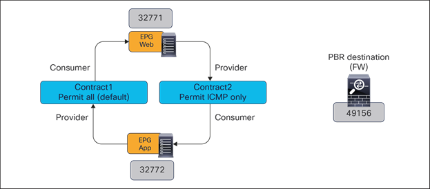
EPG class IDs and contracts (after service-graph deployments)
Table 5. Permit and redirects rules with service graphs
|
|
Source class ID |
Destination class ID |
Filter |
Action |
Zoning-rule priority |
| Contract1 |
32271 (Web EPG) |
32772 (App EPG) |
default (permit any) |
Redirect to destgrp-5 (FW-internal) with redir_override |
9 |
| 49156 (FW-internal) |
32772 (App EPG) |
default (permit any) |
Permit |
9 |
|
| 32772 (App EPG) |
32271 (Web EPG) |
default (permit any) |
Redirect to destgrp-5 (FW-internal) |
9 |
|
| 49156 (FW-internal) |
32271 (Web EPG) |
default (permit any) |
Permit |
9 |
|
| Contract2 |
32271 (Web EPG) |
32772 (App EPG) |
Permit ICMP only |
Redirect to destgrp-5 (FW-internal) |
7 |
| 49156 (FW-internal) |
32772 (App EPG) |
Permit ICMP only |
Permit |
7 |
|
| 32772 (App EPG) |
32271 (Web EPG) |
Permit ICMP only |
Redirect to destgrp-5 (FW-internal) with redir_override |
7 |
|
| 49156 (FW-internal) |
32271 (Web EPG) |
default (permit any*) |
Permit |
9 |
For more information about zoning-rules and priorities, please refer to the Contract priorities section in the ACI Contract Guide: https://www.cisco.com/c/en/us/solutions/collateral/data-center-virtualization/application-centric-infrastructure/white-paper-c11-743951.html#Contractpriorities.
Figure 134 shows how to check the destinations for a redirect destination group (destgrp).
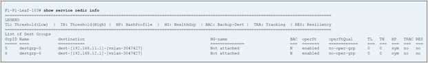
If you check the same information on the APIC and on the leaf nodes in site2, you will see similar outputs with different class IDs because each site uses different class IDs. With ACI Multi-Site, the spines have translation tables to change the class IDs for intersite traffic so that policy can be maintained consistently across sites (namespace normalization).
Figure 135 shows the translation tables and class IDs in site1 and site2.
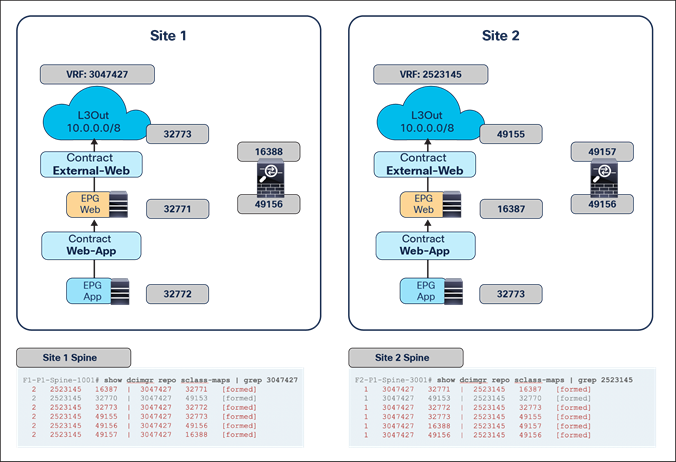
Translation tables on spine nodes
Table 6. EPG class ID translation
| EPG/VRF |
Site1 class ID |
Site1 VRF |
Site2 class ID |
Site2 VRF |
| Web EPG |
32271 |
3047427 |
16387 |
2523145 |
| App EPG |
32772 |
3047427 |
32773 |
2523145 |
| L3Out EPG |
32773 |
3047427 |
49155 |
2523145 |
| FW-external |
16388 |
3047427 |
49157 |
2523145 |
| FW-internal |
49156 |
3047427 |
49156 |
2523145 |
Note: 49153 in site1 and 32770 in site2 are the VRF class IDs.
If you don’t see the traffic in the service node even though you see zoning-rules and translation tables accordingly programmed on the switch nodes, the traffic might be dropped somewhere else or the policy might not be enforced on the leaf node. To check specific forwarding information on each ACI switch node, ELAM (Embedded Logical Analyzer Module) Assistant App is available. For more information, see Cisco DC App Center: https://dcappcenter.cisco.com/.
Example2: vzAny-to-vzAny contract with PBR
In the case of vzAny-to-vzAny contract with permit, by default, 0-to-0 permit zoning-rules are programmed on the leaf nodes; 0 represents vzAny. If there is no port-number specified in the filter used in the contract, it will be one 0-to-0 zoning-rule because the consumer-to-provider and provider-to-consume rules are identical.
If “Site-aware Policy Enforcement Mode” is enabled on the VRF for vzAny PBR, a set of zoning-rules is programmed for each site. Please see the zoning-rules output in the figure below to understand the reason for this. vzAny PBR uses a special behavior explained in Figure 27 to redirect traffic back to the PBR destination in the source site if the ingress leaf in the source site has not learned the destination endpoint. Thus, leaf nodes need to obtain different redirect zoning-rules for each site. In this example, one zoning-rule is to redirect traffic to the PBR destination in a local site (destgrp-7), and the other zoning-rule is to redirect traffic to the PBR destination in another site (destgrp-8).
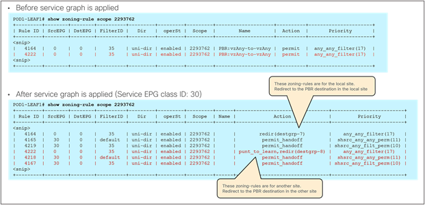
Zoning-rules for vzAny-to-vzAny contract with PBR
Although a vzAny-to-vzAny contract with PBR itself would consume less TCAM resources than multiple EPG-to-EPG and L3Out-to-EPG contracts with PBR, please be aware that enabling “Site-aware Policy Enforcement Mode” will increase TCAM resource consumption in the VRF.
Where policy is applied could be different depending on the endpoint-learning status in the case of vzAny PBR. To identify if endpoint is learned through conversational learning or not, you can use the “show system internal epm” command.
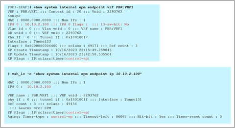
Check to see if endpoint has been learned through conversational learning
This section covers frequently asked questions regarding this solution.
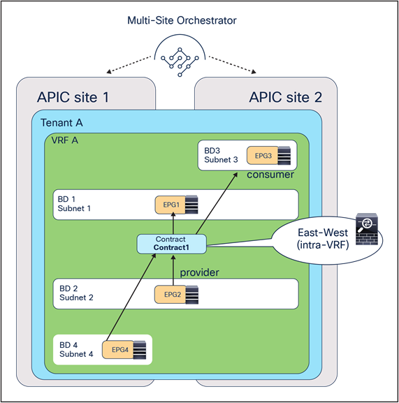
Multiple EPGs consuming and providing the same contract with PBR
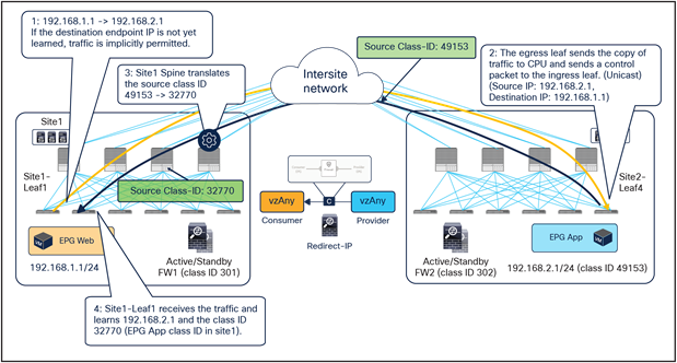
Conversational learning for endpoint-to-endpoint communication (unicast)
Differently from endpoint-to-endpoint traffic, the class ID translation is not performed for the unicast traffic toward an intersite L3Out (please see the intersite L3Out section in Cisco ACI Multi-Site Architecture White Paper for details). Because of this, for external-to-endpoint traffic, the egress compute leaf cannot use a unicast control packet for conversational learning (since this conversational learning packet will be in the endpoint-to-external direction that does not carry the translated source class ID). Therefore, to circumvent this, the egress compute leaf uses a multicast control packet instead of unicast in the endpoint-to-external direction. The class ID translation is performed even if one of the multicast destinations is a border leaf with an intersite L3Out.
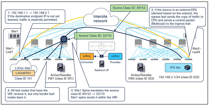
Conversational learning for external-to-endpoint communication (multicast)
There are three different deployment models to integrate service nodes with Cisco ACI Multi-Site fabrics:
● Independent active/standby service-node pair in each site (recommended).
● Active/standby service-node pair connected to separate sites (not recommended).
● Active/active service-node cluster stretched across separate sites (not recommended and not supported).
The use of PBR is the recommended approach to integrate independent firewall pairs connected to separate sites. PBR destinations can be L1/L2/L3 service nodes. Examples and considerations are summarized in Table 7.
Table 7. Service integration modes for Cisco ACI Multi-Site fabric
| Service node |
Independent service node in each site (recommended) |
| Transparent (L1/L2) mode firewall |
Yes
● ACI is gateway; use PBR
**
|
| Routed mode (L3) firewall |
Yes
● ACI is gateway; use PBR
or
● Connect firewall as an L3Out external device with host-route advertisement (north-south)
|
| Routed mode load balancer |
Yes
● NAT on load balancer
or
● ACI is gateway; use PBR for return traffic.
*
|
Multi-Site PBR supports the following contract configurations:
● EPG-to-EPG contract (one/two-arm, multiple nodes service insertion with bidirectional and unidirectional PBR).
● L3Out-to-EPG contract (one/two-arm, multiple nodes service insertion with bidirectional and unidirectional PBR).
● vzAny-to-vzAny contract (one-arm one-node service insertion with bidirectional PBR).
● vzAny-to-L3Out (one-arm one-node service insertion with bidirectional PBR).
● L3Out-to-L3Out (one-arm one-node service insertion with bidirectional PBR).
● vzAny-to-EPG (Starting from 6.1(3), one/two-arm, multiple nodes service insertion with bidirectional/unidirectional PBR. Prior to 6.1(3), one-arm one-node service insertion with bidirectional and unidirectional PBR).
Where PBR policy is applied differs based on contract configuration. Please see Table 1 and Table 2.
Cisco Application Centric Infrastructure White Papers:
ACI Multi-Pod White Paper:
Cisco Application Centric Infrastructure Policy-Based Redirect Service Graph Design White Paper:
Cisco ACI Multi-Site Architecture White Paper:
Configurations prior to Cisco Nexus Dashboard Orchestrator Release 4.2(1)
This section presents configuration examples for various use cases of services integration in a Cisco ACI Multi-Site architecture. General configuration steps for the intra-VRF one-node firewall service graph use case are covered in the section. Inter-VRF, load balancer, and two-node service graph use cases are covered in the section Additional configuration examples.
Although this section uses L3Out-to-EPG (north-south) and EPG-to-EPG (east-west) use cases, vzAny PBR and L3Out-to-L3Out can also be configured by using this old workflow. Please refer to section “Additional configuration steps”.
This section describes the general configuration steps for north-south and east-west firewall insertion using the topology in Figure 141 as an example. A two-arm-mode firewall is used for north-south communication, and a one-arm-mode firewall is used for east-west communication. This section uses this example because it is generally preferable to use different firewall interfaces for external facing and internal facing, and one-arm mode can simplify firewall-routing configuration for east-west communication. Though the same firewall is used for both north-south and east-west communications in this example, using different firewalls is also possible.
Note: This section shows GUI screenshots taken from Cisco APIC Release 4.2(1) and Cisco Multi-Site Orchestrator (MSO) Release 2.2(1). Thus, the GUI “look and feel” in this section might be slightly different from your specific APIC or MSO/NDO GUI.
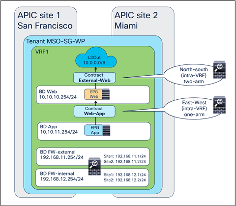
North-south traffic contract with firewall and east-west traffic contract with firewall
Some objects must be created on each APIC domain and on the Cisco Nexus Dashboard Orchestrator (NDO) before going into the service-graph and PBR–specific configurations. This section does not cover how to create tenants, VRFs, BDs, EPGs, L3Out, and contracts. The assumption is that items below are already configured.
● On the APIC in each site:
◦ Create the L3Out connections in each site (north-south use case)
● On MSO templates:
◦ Create VRF(s) and consumer, provider, and service BDs
◦ Create consumer and provider EPGs
◦ Create External-Web and Web-App contracts and ensure they are provided/consumed by the EPGs (We will then attach the service-graph to those contracts).
Note: For more information on the use of MSO schemas and templates to deploy site-specific configurations and/or objects stretched across sites, please refer to the configuration guide below: https://www.cisco.com/c/en/us/td/docs/switches/datacenter/aci/aci_multi-site/sw/2x/configuration/Cisco-ACI-Multi-Site-Configuration-Guide-221/Cisco-ACI-Multi-Site-Configuration-Guide-221_chapter_0110.html.
For the deployment of a service graph with PBR specific to a Cisco ACI Multi-Site architecture, there are different configuration steps that must be performed on each APIC domain and on the Cisco Nexus Dashboard Orchestrator:
● On the APIC in each site:
◦ Create the L4–L7 device(s) (logical device(s))
◦ Create the PBR policy
● On MSO at the template level:
◦ Create the service graph
◦ Associate the service graph with the contract
◦ For the east-west use case, configure the IP subnet under the consumer EPG
● On MSO at the site level:
◦ Select the L4–L7 device(s) (logical device(s)) exposed from each APIC domain
◦ Select the cluster interface(s) and the PBR policy
The following sections provide more detailed information on each of the configuration steps listed above.
The steps explained in this section must be performed in each APIC domain. Because the PBR redirection of traffic to a service node deployed in a remote site is not supported, it is currently mandatory for each site to have deployed at least one local L4–L7 device and an associated PBR policy (the various options to provide redundancy to the service node functions offered in the local site were shown in Figure 9).
Create the L4–L7 device (logical device)
This step needs to be repeated in each APIC domain.
Notice how the L4–L7 device configuration has no PBR-specific configuration. One or more L4–L7 devices can be configured. In this example, two devices are configured, ASAv1 and ASAv2, as an active/standby high-availability cluster pair. Though an active/standby virtual firewall is used in this example, use of more than two devices and physical domains is supported as well.
The location is Tenant > Services > L4-L7 > Devices.
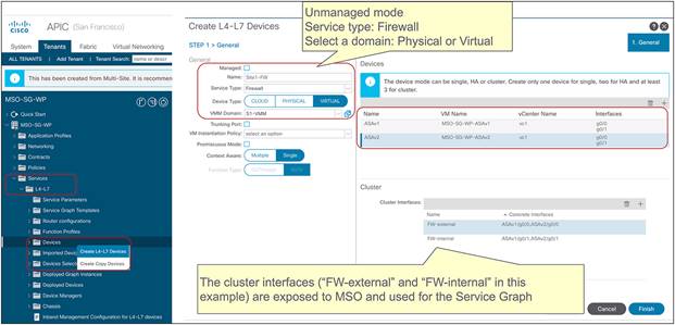
Create the L4–L7 device on APIC
Configuration specifics used in this document are as follows:
● Unmanaged mode (Multi-site supports unmanaged-mode service graphs only.)
● L4–L7 device name: Site1-FW or Site2-FW
● Service type: firewall
● Device type: VIRTUAL
● VMM domain: S1-VMM or S2-VMM (This is optional; the virtual firewall could also be connected to the fabric as a physical resource instead.)
● Function type: GoTo (Layer 3 mode)
● Concrete device1: ASAv1
● Concrete device2: ASAv2
● Cluster interface FW-external is Gigabitethernet0/0 of each ASAv.
● Cluster interface FW-internal is Gigabitethernet0/1 of each ASAv.
Create the PBR policy
This step needs to be repeated in each APIC domain.
You must configure the PBR node IP address and MAC address. The PBR node IP and MAC addresses defined in the PBR policy are the virtual IP and MAC addresses for the active/standby high-availability cluster pair defined in Figure 143. Though this example doesn’t use tracking, tracking and other PBR policy options can be enabled. Tracking and other PBR policy options could be useful if there are multiple PBR destinations in the same PBR policy. For more information, please refer to the Cisco ACI PBR white paper: https://www.cisco.com/c/en/us/solutions/data-center-virtualization/application-centric-infrastructure/white-paper-c11-739971.html.
The location is Tenant > Protocol Policies > L4-L7 Policy Based Redirect.
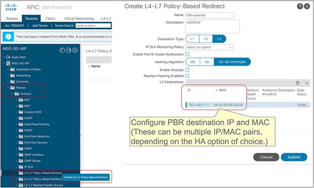
Because this example uses two interfaces of the firewall, two PBR policies per site need to be configured. Configurations used in this document are as follows:
● Site1 (San Francisco)
◦ FW-external: 192.168.11.1 with MAC 00:50:56:95:26:00
◦ FW-internal: 192.168.12.1 with MAC 00:50:56:95:c1:ae
● Site2 (Miami)
◦ FW-external: 192.168.11.2 with MAC 00:50:56:a0:92:ef
◦ FW-internal: 192.168.12.2 with MAC 00:50:56:a0:c1:e0
Note: Starting from Cisco APIC Release 5.2, MAC configuration is not mandatory for L3 PBR if IP-SLA tracking is enabled. The dynamic MAC address detection feature is also useful for the case where the active/standby high-availability cluster pair doesn’t use the virtual MAC address because the MAC address of the PBR destination IP is changed after the failover.
MSO template–level configuration
Create the service graph
Create the service graph in the MSO template associated to a specific tenant and mapped to all the sites where such tenant is deployed. The service graph is an abstract definition of the sequence of service functions required between EPGs. In this example, we are going to create a service graph with a firewall node, since the intent is to redirect through the firewall the traffic flows (all of them or specific ones) between the pair of specified EPGs.
The location is Schema > TEMPLATES > SERVICE GRAPH.
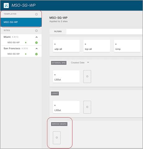
Add the service-graph object on NDO
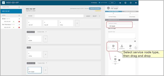
Configure the service graph on NDO
Associate the service graph with the contract
Associate the service graph with the contract. A service graph can be associated to one or more contracts. In this example, we are going to associate the FW-Graph created in the previous step with both north-south and east-west contracts. It’s worth mentioning that redirection is done for the specific traffic matched with the filters in the contract with the service graph. If there is another contract without service graph between the same consumer and provider EPGs, that traffic is not redirected.
When you click a service node, a pop-up window opens up asking you to select the bridge domains to be used for the consumer and provider connectors of the service node. In our specific example, we want to use a two-arm firewall to enforce security policies for north-south communication, thus two different BDs are specified (FW-external BD for the consumer connector and FW-internal BD for the provider connector). Those BDs must have been previously provisioned as stretched objects from MSO (that is, configured as “L2 Stretched” in a template associated to both sites, with BUM forwarding disabled to help containing the propagation of L2 flooding across the sites).
The location is Scheme > TEMPLATES > CONTRACT.
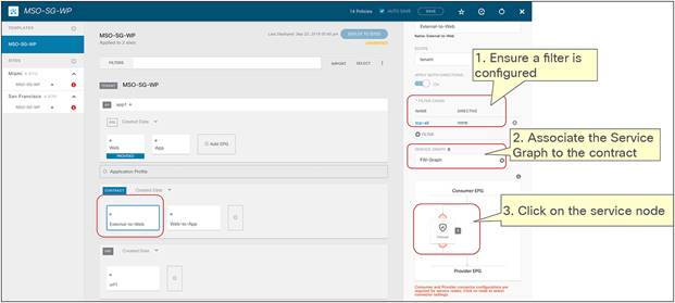
Associate the service graph with the contract for north-south (two-arm use case)
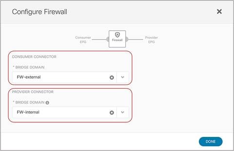
Select BDs for the consumer and provider connectors for north-south (two-arm)
The step needs to be repeated for the other contract that is for east-west communication. For enforcing security policies on east-west communication, we want instead to use in our specific example a firewall node deployed in one-arm mode. This implies that the same FW-internal BD can be specified for both the consumer and the provider connectors.
Note: It is important to ensure that the deployed firewall model (virtual or physical) can support one-arm mode deployments. For example, with Cisco ASA and FTD models, a specific configuration command must be enabled for supporting this use case. You can find more information at the links below: https://www.cisco.com/c/en/us/support/security/asa-5500-series-next-generation-firewalls/products-installation-and-configuration-guides-list.html.

Associate the service graph with the contract for east-west traffic flows (one-arm use case)
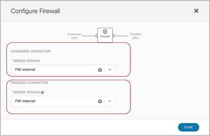
Selected BDs to the consumer and provider connectors for east-west traffic flows (one-arm use case)
In summary, the specific configurations used in this document for the deployment of the service node connectors are as follows:
● North-south contract (two-arm firewall)
◦ Consumer connector: FW-external BD
◦ Provider connector: FW-internal BD
● East-west contract (one-arm firewall)
◦ Consumer connector: FW-internal BD
◦ Provider connector: FW-internal BD
Configure the IP subnet under the consumer EPG (east-west use case)
As mentioned in the first part of this document, when applying a PBR policy for east-west policy enforcement on the firewall, it is critical to avoid creating asymmetric traffic paths through the independent service nodes deployed in each site. This can be achieved by “anchoring” the application of the PBR policy on the provider leaf node (that is, the leaf node where the provider endpoint is connected). In order to achieve this, it is currently required to configure the IP subnet under the consumer EPG to install the consumer EPG class ID classification information associated with the subnet to the provider leaf because PBR policy is always applied on the provider leaf.
Note: If running ACI Release 3.2(x), the IP subnet must be configured under the provider EPG instead of under the consumer EPG, since the PBR policy in this case is always applied on the consumer leaf node.
The location is Schema > AP > EPG.
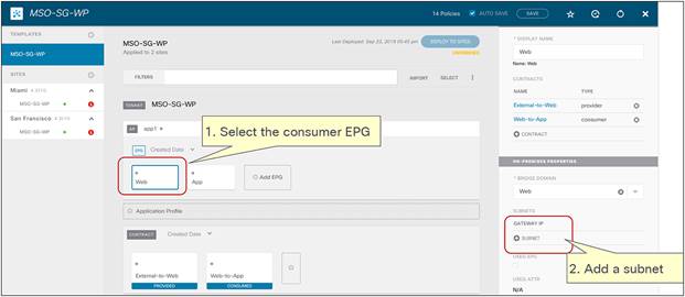
Select the consumer EPG
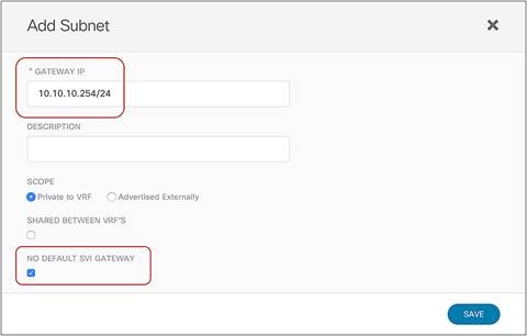
Configure the IP subnet under the consumer EPG for an east-west use case
Configurations used in this document are as follows:
● Web EPG (consumer for east-west contract)
◦ 10.10.10.254/24 (This usually matches the IP subnet configured under the corresponding Web BD).
◦ NO DEFAULT SVI GATEWAY (It’s because you should have already defined the IP subnet to be used as the default gateway as part of the Web BD configuration).
At this point, you can probably notice the appearance of a red information icon in each site-level configuration. This simply means that some site-specific configuration must still be completed. Hence the next step, performed at the site level, consists in selecting the L4–L7 device to use and its specific connectors.
The L4–L7 device and its connectors configured in the previous section should be offered as the options to select. If you don’t see those options, please verify to have defined an L4–L7 logical device in each APIC domain (as previously shown in the section “Create the L4–L7 device (logical device)”).
Select the L4–L7 device exposed by APIC
Select the L4–L7 device for the service graph. You need to repeat this step for each site-level configuration.
The location is Schema > SITE > SERVICE GRAPH.
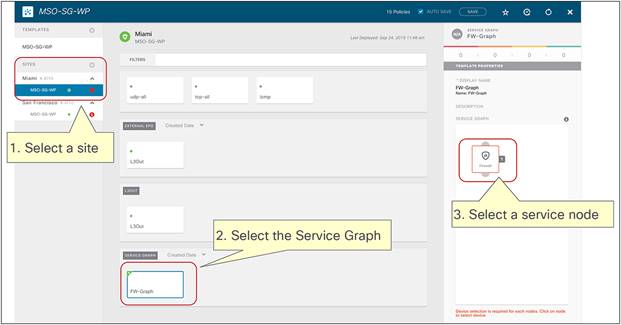
Select the service-graph object.
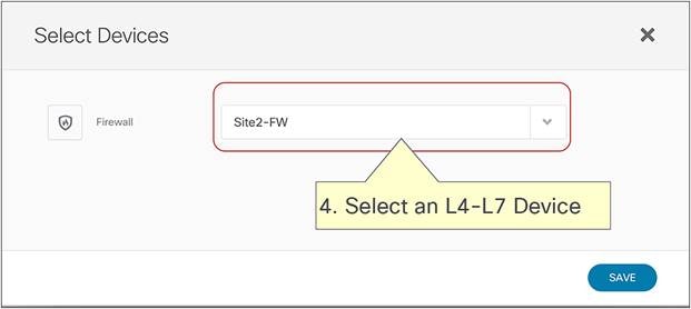
Configurations used in this document are as follows:
● Site1 (San Francisco)
◦ Site1-FW (active/standby pair deployed in Site1)
● Site2 (Miami)
◦ Site2-FW (active/standby pair deployed in Site2)
Select the cluster interface and the PBR policy
Select the connectors for each contract with the service graph. You need to repeat this step for each site-level configuration.
For the two-arm firewall deployment used for north-south policy enforcement, it is required to specify two different interfaces as connectors (FW-external and FW-internal) and associate a specific PBR policy to each. This is because inbound traffic flows originating from external clients must be redirected to the external interface of the firewall before reaching the internal destination endpoint, whereas outbound traffic flows destined to the external clients must be redirected to the internal interface of the firewall.
The location is Schema > SITE > CONTRACT > SERVICE GRAPH.

Select the service node in the service graph for north-south (two-arm)
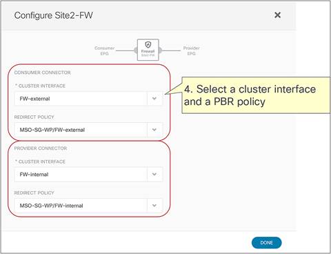
Select the cluster interface and the PBR policy for north-south (two-arm)
For the one-arm firewall deployment used for east-west policy enforcement, it is required to specify the same interface (FW-internal) as both the consumer and provider connectors and to associate the same PBR policy to it. This is because east-west traffic flows must always be redirected to the same firewall interface for both consumer-to-provider and provider-to-consumer directions.
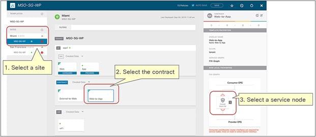
Select the service node in the service graph for east-west traffic flows (one-arm use case)
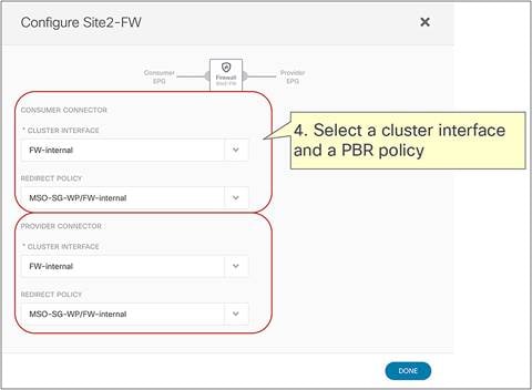
Select the cluster interface and the PBR policy for east-west traffic flows (one-arm use case)
In summary, the specific site-level configurations used for our example are as follows:
● North-south contract
◦ Consumer connector
◦ Cluster interface: FW-external
◦ PBR policy: FW-external
◦ Provider connector
◦ Cluster interface: FW-internal
◦ PBR policy: FW-internal
● East-west contract
◦ Consumer connector
◦ Cluster interface: FW-internal
◦ PBR policy: FW-internal
◦ Provider connector
◦ Cluster interface: FW-internal
◦ PBR policy: FW-internal
The final step is to deploy the template.
The location is Scheme > TEMPLATES.
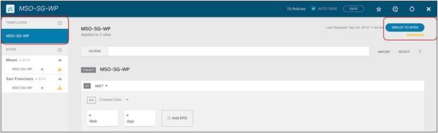
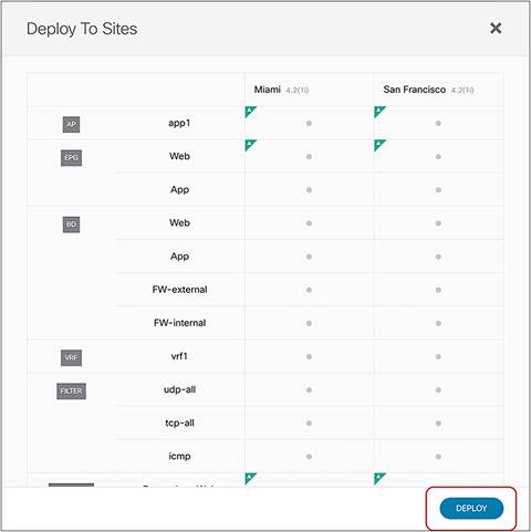
Additional configuration examples
This section covers configuration examples using the workflow prior to Cisco Nexus Dashboard Orchestrator Release 4.2(1) for the use cases listed below. Because most of the configuration steps are identical to the ones already shown in the example in the previous section using a firewall-only service graph, this section mostly covers configuration considerations, and not all of the detailed steps.
● Two-node service graph with firewall and load balancer
● Intra-tenant Inter-VRF service graph with firewall only
● Inter-tenant inter-VRF service graph with firewall only
● Intra-tenant inter-VRF service graph with firewall and load balancer
● One-node service graph with firewall for vzAny-to-vzAny contract
Note: This section uses GUI screenshots taken from Cisco ACI Release 4.2(1) and Cisco Multi-Site Orchestrator (MSO) Release 2.2(1), except for the vzAny contract with PBR configuration example, which uses Cisco ACI Release 6.0(4c) and Cisco Nexus Dashboard Orchestrator (NDO) Release 4.2(3e). Thus, the GUI “look and feel” in this document might be slightly different from your specific ACI or NDO GUI.
Two-node service graph with firewall and load balancer
This is a two-node service-graph deployment example where traffic must be steered through a service-node chain with a firewall and a load balancer. In addition to the configuration required for redirection to the firewall, you also need to configure the L4–L7 logical device and the PBR policy for the load balancer. If the load balancer performs SNAT, a PBR policy for the load balancer is not needed.
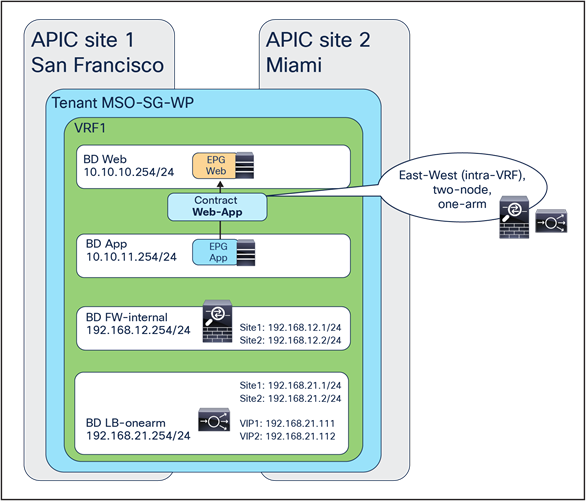
Two-node service graph with firewall and load balancer (east-west)
Specific configuration considerations for this design are as follows:
● Deploy the subnet under the consumer EPG for the east-west service graph
● Configure L4–L7 devices and PBR policies for both the firewall and the load balancer (at the APIC level)
● Create a two-node service graph on MSO
In addition to an L4–L7 device for the firewall, an L4–L7 device and a PBR policy for the load balancer need to be configured on each APIC domain. Though an active-standby high-availability cluster pair of load balancers should be used in real life deployments, we use one load balancer with one-arm design in this configuration example.
The location is Tenant > Services > L4-L7 > Devices.
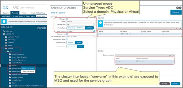
L4–L7 device for load balancer (APIC in each site)
If the load balancer does not perform SNAT, in addition to a PBR policy for the firewall, we also need a PBR policy to steer through the load balancer the return flow originated from the real server.
The location is Tenant > Protocol Policies > L4-L7 Policy Based Redirect.
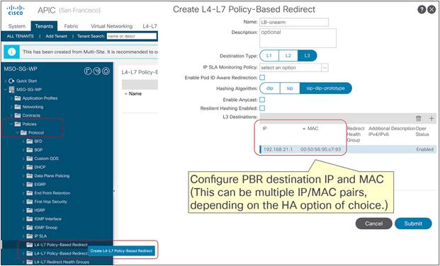
PBR policy for load balancer (APIC in each site)
Create the service graph in the MSO template. In this example, we are going to create a service graph with firewall and load balancer.
The location is Scheme > TEMPLATES > SERVICE GRAPH.
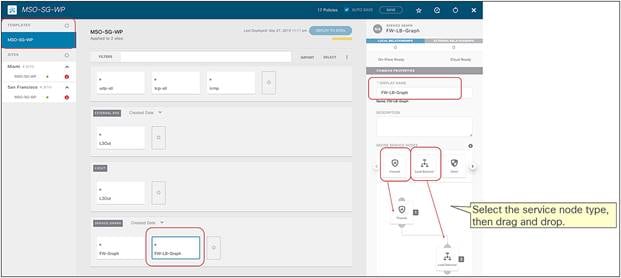
Create a two-node service graph (MSO-template level)
Associate the service graph with the contract.
The location is Scheme > TEMPLATES > CONTRACT.
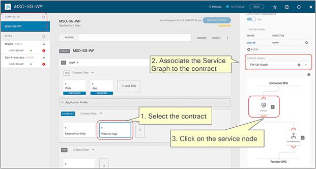
Associate the service graph with the east-west contract (firewall and load balancer)
When you click a service node, a pop-up window opens up asking you to select the bridge domains for the consumer and provider connectors. In this this example, both the firewall and load balancer are deployed in one-arm mode. Hence, FW-internal BD is used for both consumer and provider connectors of the firewall, and the LB-onearm BD is used for both consumer and provider connectors of the load balancer.
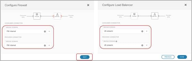
Select BDs for the consumer and provider connectors (firewall and load balancer)
Select the L4-L7 Device for Service Graph. You need to repeat this step for each site-level configuration.
The location is Scheme > SITE > SERVICE GRAPH.
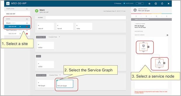
Select the service-graph object
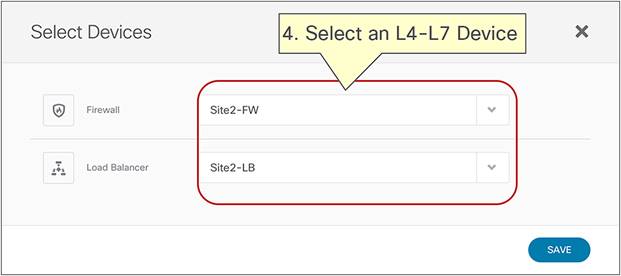
Select the L4–L7 device (MSO-site level)
Select the connectors for each contract where the service graph is applied. You need to repeat this step for each site-level configuration. After that, the template needs to be deployed to the sites.
The location is Scheme > SITE > CONTRACT > SERVICE GRAPH.
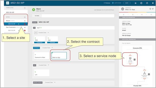
Select the contract and the service node
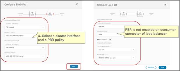
Select the cluster interface and the PBR policy (MSO-site level)
Note: If the load balancer does not perform SNAT, the PBR policy needs to be selected on the provider connector of the load balancer, as shown in Figure 169. If the load balancer performs SNAT, there is no need to associate a PBR policy to the provider or to the consumer connector of the load balancer.
Intra-tenant inter-VRF service graph with firewall
This is a specific example of inter-VRF policy enforcement via redirection to a firewall node. The contract scope and BD subnet options need to be configured accordingly, as explained in the rest of this chapter.
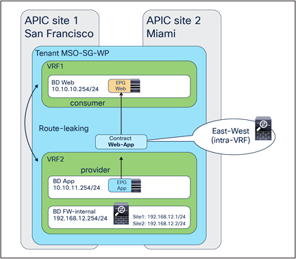
Intra-tenant inter-VRF service graph with firewall
Note: The firewall BD can be in either the consumer or the provider VRF.
Configuration considerations for this design are as follows:
● Contract scope must be “application-profile,” “tenant,” or “global” for inter-VRF policy enforcement (since this contact is applied between EPGs belonging to separate VRFs).
● The consumer and provider EPG subnet options must be set to “shared between VRFs” for inter-VRF route leak.
The location is Schema > TEMPLATE > CONTRACT > SCOPE.
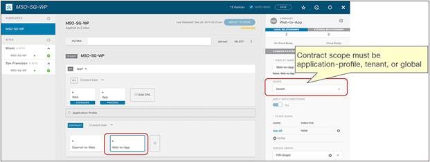
Contract scope setting (MSO-template level)
Since this is an inter-VRF contract, the subnet under the provider EPG must be set (to enable route-leaking) in addition to the subnet under the consumer EPG required for a service graph with ACI Multi-Site. Also, both consumer and provider EPG subnets need to be have “shared between VRF’s” enabled to leak the subnets between VRFs.
The location is Scheme > TEMPLATE > EPG > GATEWAY IP.
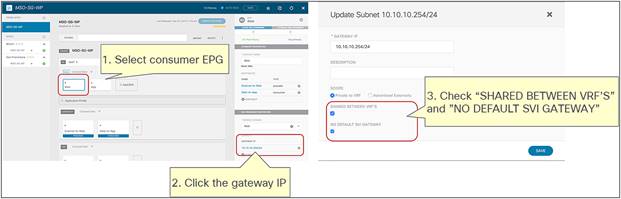
Select the gateway IP object
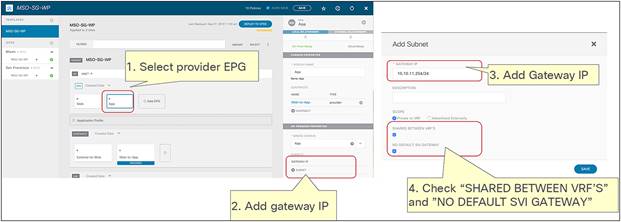
Consumer and provider EPG subnet options (MSO-template level)
Figure 174 shows a verification example for inter-VRF route leaking. After the template is deployed, both consumer and provider VRFs should have both consumer and provider subnets.
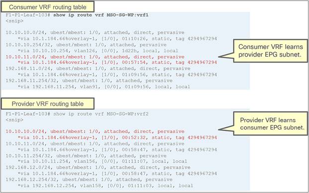
Consumer and provider VRFs’ routing tables
Inter-tenant inter-VRF service graph with firewall
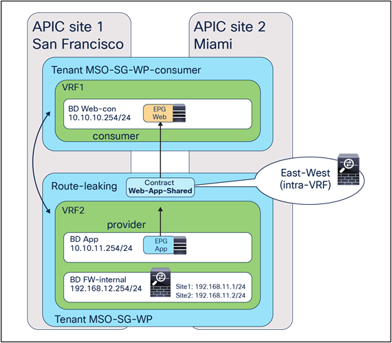
Inter-tenant inter-VRF service graph with firewall
Configuration considerations for this design are as follows:
● Contract scope must be “global” for inter-tenant inter-VRF policy enforcement.
● Consumer and provider EPG subnets’ options must be set to “shared between VRFs” for enabling inter-VRF route-leaking.
● Service-graph template and contract must be defined in the provider tenant.
● L4–L7 device, PBR policy, and service BD must be referable from the provider tenant.
Note: General inter-tenant and inter-VRF contracts with PBR consideration are applied to Multi-Site service integrations as well. Please take a look at the inter-VRF configuration examples in the ACI PBR white paper: https://www.cisco.com/c/en/us/solutions/data-center-virtualization/application-centric-infrastructure/white-paper-c11-739971.html#_Toc17153755.
In this example, a template for provider and a template for consumer are defined in the same schema on MSO. MSO-SG-WP is the template associated to the provider tenant, whereas MSO-SG-WP-consumer is the template used for the consumer tenant. Figure 176 summarizes what is configured in each template.
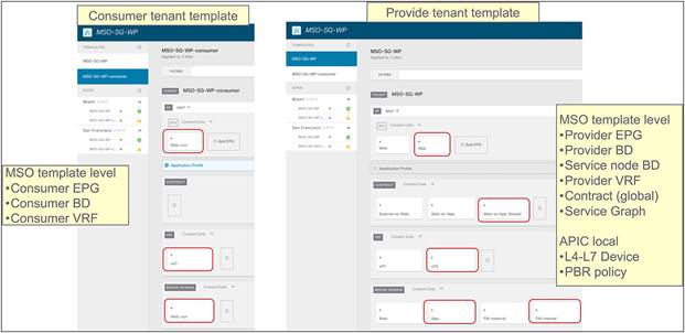
Consumer-tenant template and provider-tenant template (MSO-template level)
Since this is an inter-tenant contract, the contract scope must be global. The contract with global scope is visible from other tenants, thus the consumer EPG can consume that contract.
The location is Scheme > TEMPLATE > CONTRACT > SCOPE.
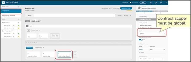
Contract-scope setting in a provider tenant (MSO-template level)
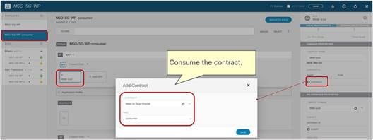
Contract relationship in a consumer tenant (MSO-template level)
The remaining steps are the same as those described for the intra-tenant inter-VRF configuration.
Intra-tenant inter-VRF service graph with firewall and load balancer
This is an intra-tenant inter-VRF two-node service-graph deployment example. It combines two previous deployments: two-node service graph with firewall and load balancer and intra-tenant inter-VRF service graph with firewall. Please take a look at the sections, above, covering these examples to understand the considerations for each deployment.
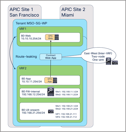
Intra-tenant inter-VRF service graph with firewall and load balancer
The additional consideration for this deployment example is the need to leak the VIP address of the load balancer to the consumer VRF if the load balancer BD is in the provider VRF. Otherwise the consumer endpoint cannot reach the VIP address in the different VRF. Though this sub-section uses an intra-tenant inter-VRF service graph, this consideration is applicable to inter-tenant inter-VRF too.
Note: This is a general consideration for an inter-VRF contract if you need to allow direct communication between the consumer or provider EPG and the PBR node interface, such as a communication between the consumer EPG and the VIP address of the load balancer. Please take a look at the ACI PBR white paper.
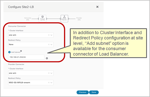
Configure the subnet to leak the load balancer subnet to the other VRF (MSO-site level)
By configuring Add Subnets, the subnet is leaked to the consumer VRF, as shown below:
F1-P1-Leaf-101# show in route vrf MSO-SG-WP:vrf1
<snip>
10.10.10.0/24, ubest/mbest: 1/0, attached, direct, pervasive
*via 10.1.56.64%overlay-1, [1/0], 00:02:28, static, tag 4294967294, rwVnid: vxlan-2097156
10.10.10.254/32, ubest/mbest: 1/0, attached, pervasive
*via 10.10.10.254, vlan69, [0/0], 00:05:03, local, local
192.168.21.0/24, ubest/mbest: 1/0, attached, direct, pervasive
*via 10.1.56.64%overlay-1, [1/0], 00:05:03, static, rwVnid: vxlan-2457601
In this example, the provider EPG subnet doesn’t have to be leaked to the consumer VRF unless the consumer endpoints need to talk to the provider endpoints directly.
Other steps are the same as those described for the two-node service graph with firewall and load balancer, and intra-tenant inter-VRF configuration.
One-node service graph with firewall for vzAny-to-vzAny contract
This is a deployment example of intra-tenant intra-VRF one-node firewall service graph for a vzAny-to-vzAny contract, which is also applicable to vzAny-to-EPG, vzAny-to-L3Out, and L3Out-to-L3Out contracts with PBR. The service-graph configuration for each of these use cases is identical; it is one-arm one-node firewall insertion with PBR enabled in both directions, with the following exception: vzAny-to-EPG that supports two-arm multiple nodes insertion with unidirectional PBR as well. vzAny-to-vzAny, vzAny-to-EPG, and a vzAny-to-L3Out contract with PBR support an intra-VRF contract only, whereas an L3Out-to-L3Out contract with PBR supports both intra- and inter-VRF contracts. For inter VRF, the service BD must be in either the consumer or the provider VRF.
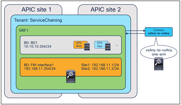
One-node service graph with firewall for vzAny-to-vzAny contract
Prerequisites
In the case of the workflow prior to Cisco Nexus Dashboard Orchestrator Release 4.2(1), L4-L7 Device and PBR policy need to be configured on APIC for each site. Please take a look at the previous sections to understand how to define L4-L7 devices and PBR policies on APIC.
As in the case for vzAny-to-vzAny, vzAny-to-EPG, vzAny-to-L3Out, and L3Out-to-L3Out contracts with PBR, the L3 Multicast and Site-aware Policy Enforcement Mode flags must be enabled (Figure 114). For L3 Multicast, the configuration of Rendezvous Points (RPs) is not required.
As previously shown, the provider and service BDs must be configured in Hardware Proxy mode (Figure 115).
Configure service graph
Service graph is configured by associating one or more service devices with a contract. This is provisioned from Configure > Tenant Template > Applications > Create Object > Service Graph.
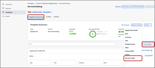
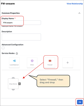
Create service graph (template-level configuration)
Select the L4-L7 Device for Service Graph. You need to repeat this step for each site-level configuration.
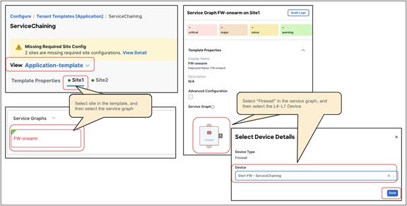
Select a service device in each site (site-level config)
Back to the template-level configuration, at the bottom of the contract’s configuration, ensure that Service Graph is selected and select the service graph. Then select the Firewall icon and select the service BDs for the consumer and the provider connectors of the firewall.

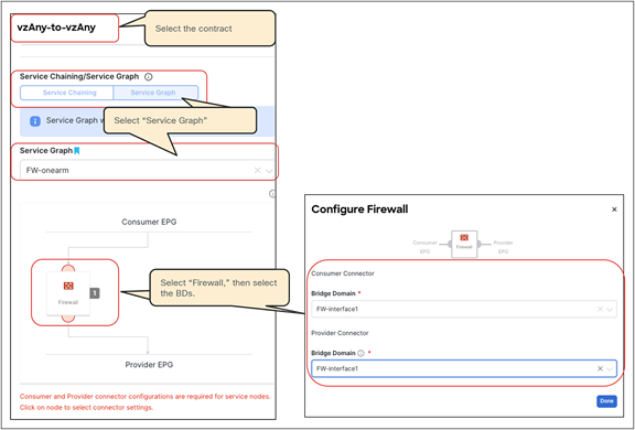
Attach the service graph to the contract (template-level)
Select the connectors for each contract where the service graph is applied. You need to repeat this step for each site-level configuration. After that, the template needs to be deployed to the sites.
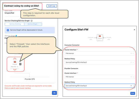
Select interfaces and PBR policies (site-level)
[1] Note: For use cases that redirect traffic in both source and destination site (that are vzAny-to-vzAny, vzAny-to-L3Out and L3Out-to-L3Out), an active/active clustered firewalls across sites shouldn’t be used regardless it's spanned etherchannel or individual modes because the cluster is not supposed to receive the same flow multiple times and it will potentially drop traffic depending on the cluster implementation.
[2] Note for advanced readers: When an ingress leaf applies a contract policy, the SP (source policy) and DP (destination policy) bits are set to 1 in the VXLAN header so that the destination leaf can identify whether the policy was already applied or not. If SP=1 and DP=1, the destination leaf does not apply the policy again. A new behavior has been introduced to support the vzAny PBR use cases: a service leaf node will set SP=0 and DP=1 for traffic received from the firewall node that is, the traffic with the source class ID of the service EPG and destined to the consumer/provider EPG. This is to indicate that the service node (firewall) has already been inserted in the source site.