Service Graph Design with Cisco ACI (Updated to Cisco APIC Release 5.2) White Paper
Available Languages
Bias-Free Language
The documentation set for this product strives to use bias-free language. For the purposes of this documentation set, bias-free is defined as language that does not imply discrimination based on age, disability, gender, racial identity, ethnic identity, sexual orientation, socioeconomic status, and intersectionality. Exceptions may be present in the documentation due to language that is hardcoded in the user interfaces of the product software, language used based on RFP documentation, or language that is used by a referenced third-party product. Learn more about how Cisco is using Inclusive Language.
Cisco® Application Centric Infrastructure (Cisco ACI®) technology enables you to insert Layer 4 through Layer 7 (L4-L7) functions using a concept called a service graph. This document describes the service graph concept and how to design for service insertion with the following deployment modes:
● With manual stitching
● With service graph by deploying an L4-L7 device in Go-To mode
● With service graph by deploying an L4-L7 device in Go-Through mode
● With service graph Policy-Based Redirect (PBR)
Using the service graph, Cisco ACI can redirect traffic between security zones to a firewall or a load balancer, without the need for the firewall or the load balancer to be the default gateway for the servers. Cisco ACI can selectively send traffic to L4-L7 devices based, for instance, on the protocol and the Layer 4 port. Firewall inspection can be transparently inserted in a Layer 2 domain with almost no modification to existing routing and switching configurations. Cisco ACI also allows you to increase the capacity of L4-L7 devices by creating a pool of devices to which Cisco ACI can distribute traffic.
This document is updated based on Cisco APIC Release 5.2, and it assumes the use of second-generation leaf switches such as the Cisco Nexus® 9300-EX and Cisco 9300-FX platform switches, or the -EX, -FX, FX2, or -GX leaf switches.
You can deploy firewalls and load balancers with Cisco ACI with or without a service graph. To decide whether or not you should use the service graph technology, you need to understand the problem the service graph solves.
The service graph concept is considered an extension to the concept of a contract, so, by default, it operates in the mode of a consumer and provider interface. This model is ideal for inserting firewalls or, more generally, L4-L7 devices between two security zones.
Note: If you need to use a service graph for a firewall with multiple network edges (or DMZs), you will need to reuse the service graph multiple times between each pair of interfaces (or between each security zone and vzAny).
A service graph offers several advantages. Two of the biggest advantages are the capability to redirect traffic and the capability to automate the VLAN allocation between the L4-L7 device (when using virtual appliances) and the fabric.
A service graph offers the following advantages. It:
● Automatically manages VLAN assignments for virtual appliances
● Automatically connects virtual network interface cards (vNICs)
● Provides a more logical, and an application-related, view of services
● Can be configured with a redirect option, which simplifies the network design
Service graph redirect offers many advantages. It does the following:
● Eliminates the need to make firewalls or load balancers the default gateway
● Avoids the need for more complex types of designs, such as a virtual routing and forwarding (VRF) instance–L4-L7-device–VRF design
● Avoids the need to split Layer 2 domains (bridge domains) to insert, for instance, a firewall in the traffic path
● Allows you to redirect a subset of the traffic based on the protocol and port
● Allows you to filter traffic between security zones in the same Layer 2 domain (bridge domain)
● Allows you to scale the performance of the L4-L7 device by distributing traffic to multiple devices
Service insertion with Cisco ACI
In Cisco ACI, you also can configure service insertion without a service graph.
To do so, you need to create multiple bridge domains that operate just like VLANs, and you can configure EPGs to connect virtual or physical appliances.
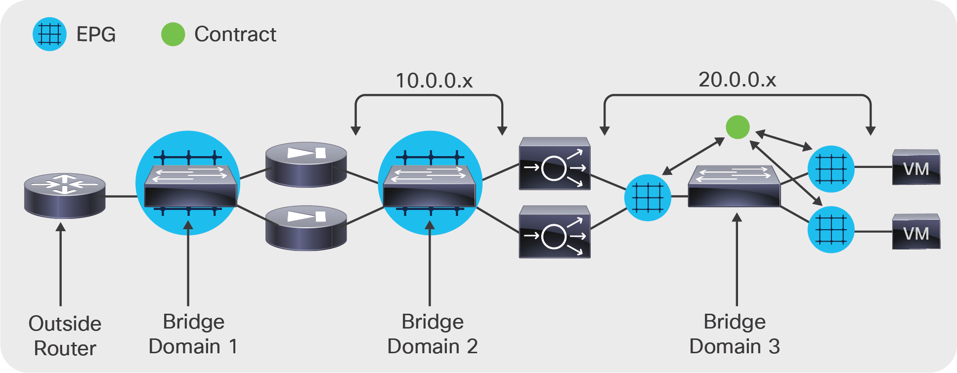
Figure 1 shows a simple multinode service insertion design. The configuration consists of multiple bridge domains and EPGs. Bridge domain 1 has an EPG to which the router and the firewall outside interface connect. Bridge domain 2 has one EPG to connect the inside interface of the firewalls and the client-side interface of the application delivery controller (ADC) device. Bridge domain 3 has an EPG for the server-side interface of the ADC device and multiple EPGs for the servers, and the EPGs are connected through contracts.
Manual configuration of service insertion
Service graph definition and main differences among Go-To, Go-Through, and policy-based redirect
A service graph specifies that the path from one EPG to another EPG must pass through certain functions:
● With service graph redirect, the service graph effectively steers traffic to the L4-L7 device.
● With the other service graph deployment modes, the service graph doesn't steer traffic to the L4-L7 device but creates contracts to prevent the traffic from going directly from one EPG to the other. Only traffic that goes through the L4-L7 device is allowed.
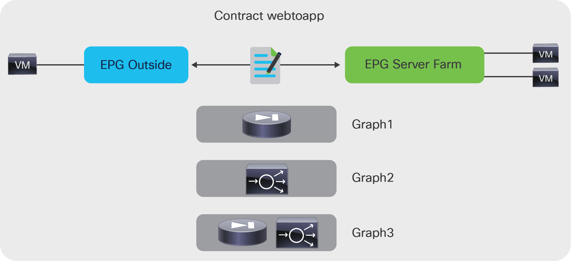
As Figure 2 illustrates, the service graph is associated with a contract between two EPGs. In the figure, the contract webtoapp can be associated with Graph1, which consists of a single firewall device; or with Graph2, which consists of a single ADC device; or with Graph3, which consists of a sequence of a firewall and an ADC device.
A contract could also have multiple "subjects" (that is, combinations of Layer 4 ports), each associated with a different graph.
A service graph is inserted between EPGs through a contract
The APIC translates the definition of the service graph into a path through firewalls and load balancers. This is based on the graph template and information provided by the user about the bridge domain to which a firewall or a load balancer should connect, as well as on the user-configured firewalls and load balancers that a given contract and graph template should use.
With the service graph, the following building blocks of the forwarding path configurations are decoupled:
● Information about each L4-L7 device: the ports to which the device is connected
● Definition of the type of graph: the type of L4-L7 devices used, the mode (Go-To, Go-Through, one-arm, redirect with Go-To, redirect with L1 or L2 mode), and the number of devices
● Bridge domain to which the L4-L7 device connects for each contract and graph instantiation
With a service graph, if you have an existing firewall deployed in a graph and you want to replace it, you simply need to define where the new firewall is connected (in the L4-L7 Device configuration). Then you specify the configuration that defines the firewall used to render the graph (in the device selection policy). Cisco ACI will then configure the network for the new firewall just like the existing one, and the graph will now point to the new firewall.
Even if the service graph provides an abstract definition of the sequence of functions required between any two EPGs, some data-plane infrastructure needs to be in place beforehand: for instance, the bridge domain (or bridge domains) to which the L4-L7 device connects.
To deploy a service graph between EPGs, you need to provision a sequence of bridge domains and potentially more than one VRF instance.
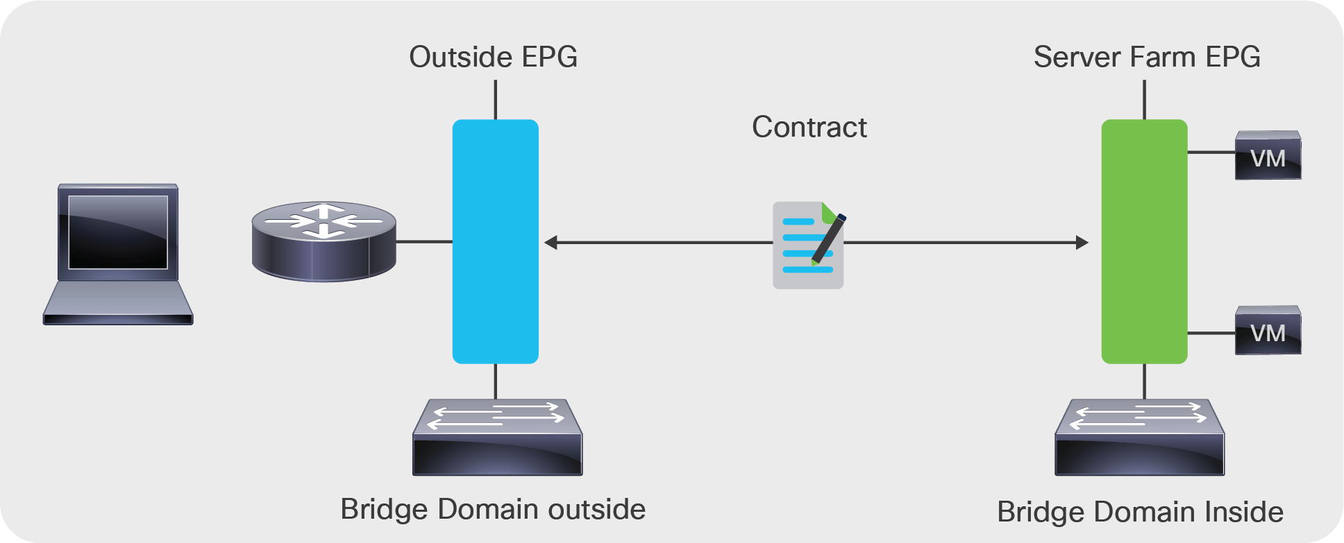
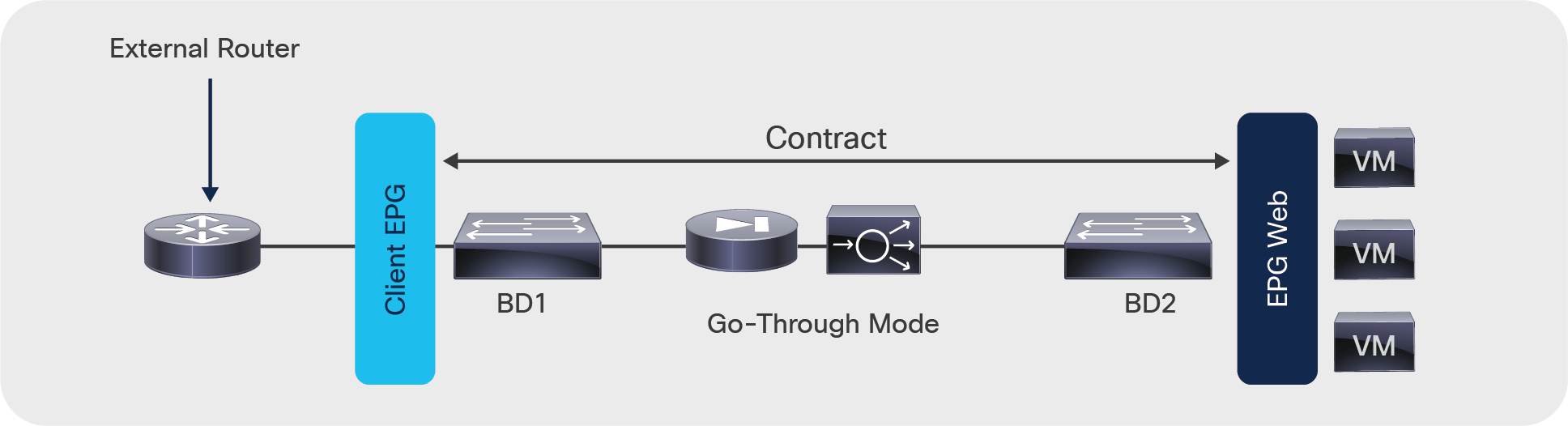
As Figure 3 shows, with Go-To or Go-Through mode, the EPG outside and the EPG server farm must be in different bridge domains for the service graph to work. In addition, the bridge domains must have a relationship with a VRF instance to be consistent with the object model.
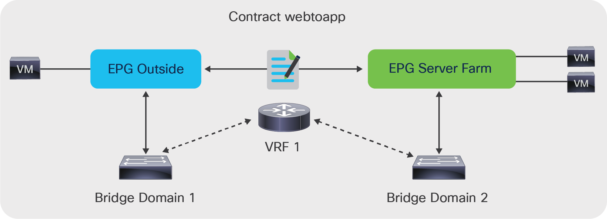
With the L4-L7 device in Go-To or Go-Through mode, EPGs must be in different bridge domains
The “rendering” involves allocation of the necessary VLANs between the L4-L7 device and the bridge domains. Cisco ACI creates EPGs to which the L4-L7 device connects, and it creates contracts to enable communication to and from the L4-L7 device (Figure 4).
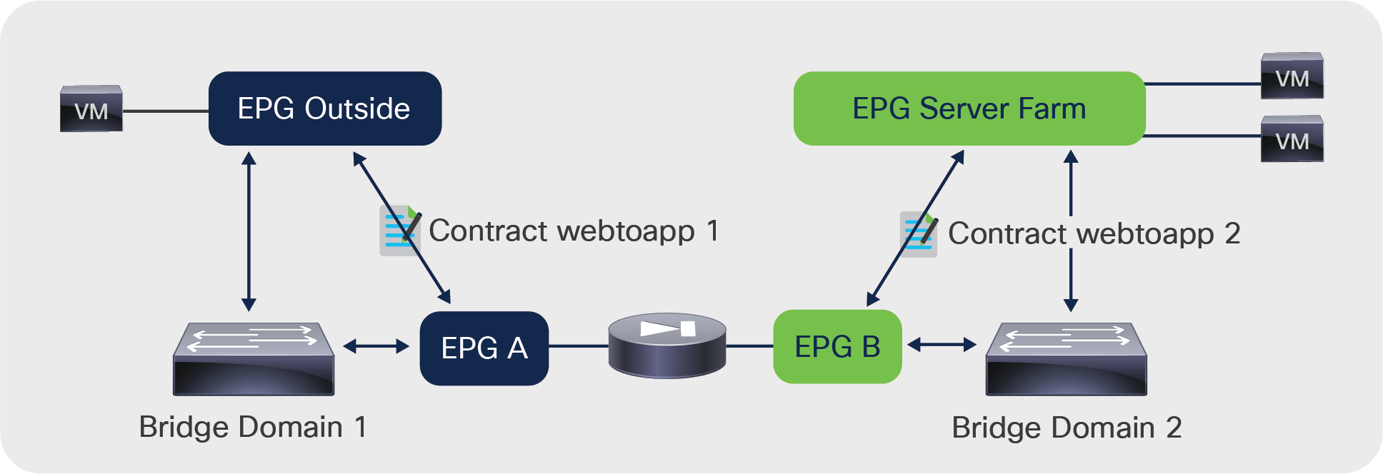
ACI creates shadow EPGs and contracts to allow communication with the L4-L7 device
When you use service graph redirect (with Go-To mode or with L1 or L2 mode), the L4-L7 device doesn't need to be connected directly to the bridge domains in which the endpoints reside. In addition, the endpoints do not need to be in different bridge domains for the traffic to traverse an L4-L7 device.
Figure 5 shows the bridge domain topology for a service graph with PBR to a firewall in Go-To mode. The firewall is connected to the bridge domain that is called L4-L7 BD in this example. Virtual machines are on BD1 and BD2. With service graph redirect, you can configure traffic from EPG1 to EPG2 to be sent through the firewall first, as well as traffic from EPG1 or EPG 2 to EPG3. You can also define a rule that says that only traffic on port 80 between EPG1 and EPG2 has to go through the firewall, whereas other traffic can go directly between EPG1 and EPG2.
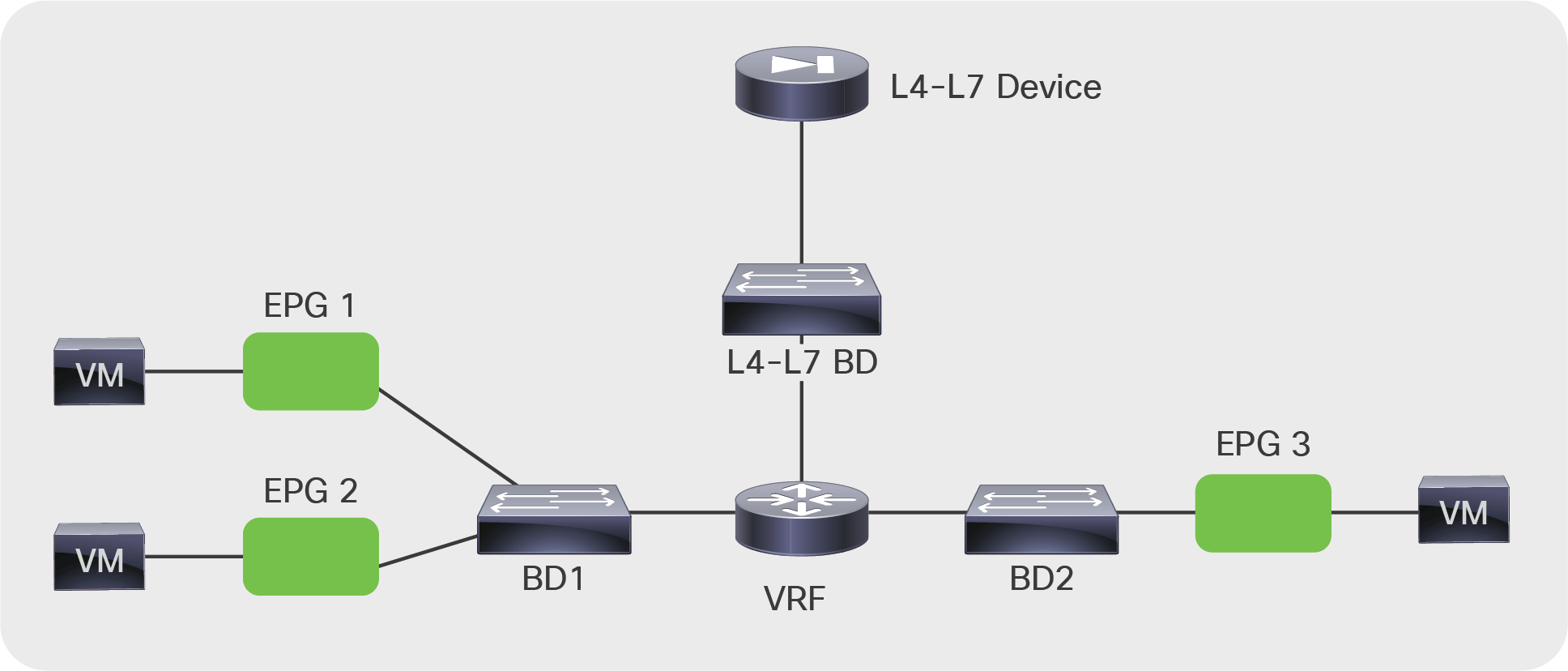
BD configuration for the deployment of an L4-L7 device in policy-based redirect (PBR) mode
When you use service graph redirect with an L1 or L2 mode L4-L7 device, the L4-L7 device needs to be connected to two dedicated bridge domains in which the endpoints do NOT reside.
Figure 6 shows a firewall connected to the two dedicated L4-L7 bridge domains. Virtual machines are on BD1 and BD2. Just as in the example illustrated in Figure 5, with service graph redirect you can configure traffic from EPG1 to EPG2 to be sent through the firewall first, as well as traffic from EPG1 or EPG 2 to EPG3.
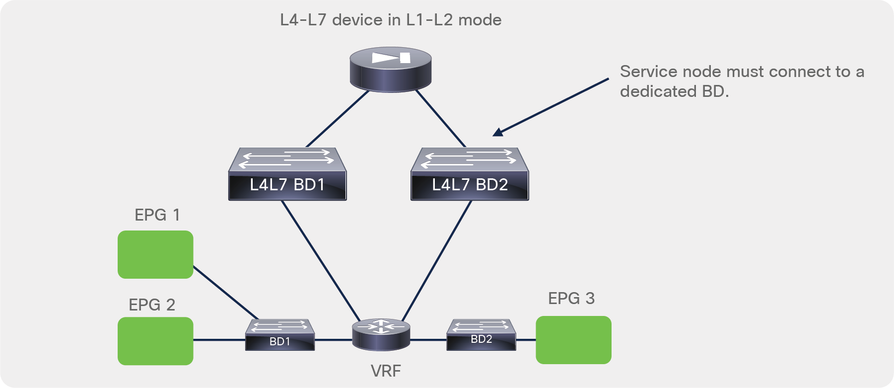
BD configuration for the deployment of an L4-L7 device in policy-based redirect (PBR) mode with L1/L2 mode
One difference between the service graph in Go-To or Go-Through mode and the redirect option is that in the first case the contract in the graph allows traffic to go through the L4-L7 device, but you have to set up separate bridge domains to have routing or bridging forward the traffic to the L4-L7 device. With redirect, the contract rule forwards traffic to the firewall regardless of the routing and bridging lookup results.
As of Cisco APIC Release 5.2, the management model for service graph deployments follows a traditional operational model in which the configuration of L4-L7 devices consists of the following steps:
● The network administrator configures the ports and VLANs to connect the firewall or the load balancer.
● The firewall administrator configures the ports and VLANs on the firewall or the load balancer.
● The firewall administrator configures the ACLs and other security features on the firewall (or load balancing features on the load balancer).
As shown in Figure 7, the network administrator configures the fabric but not necessarily the firewall.
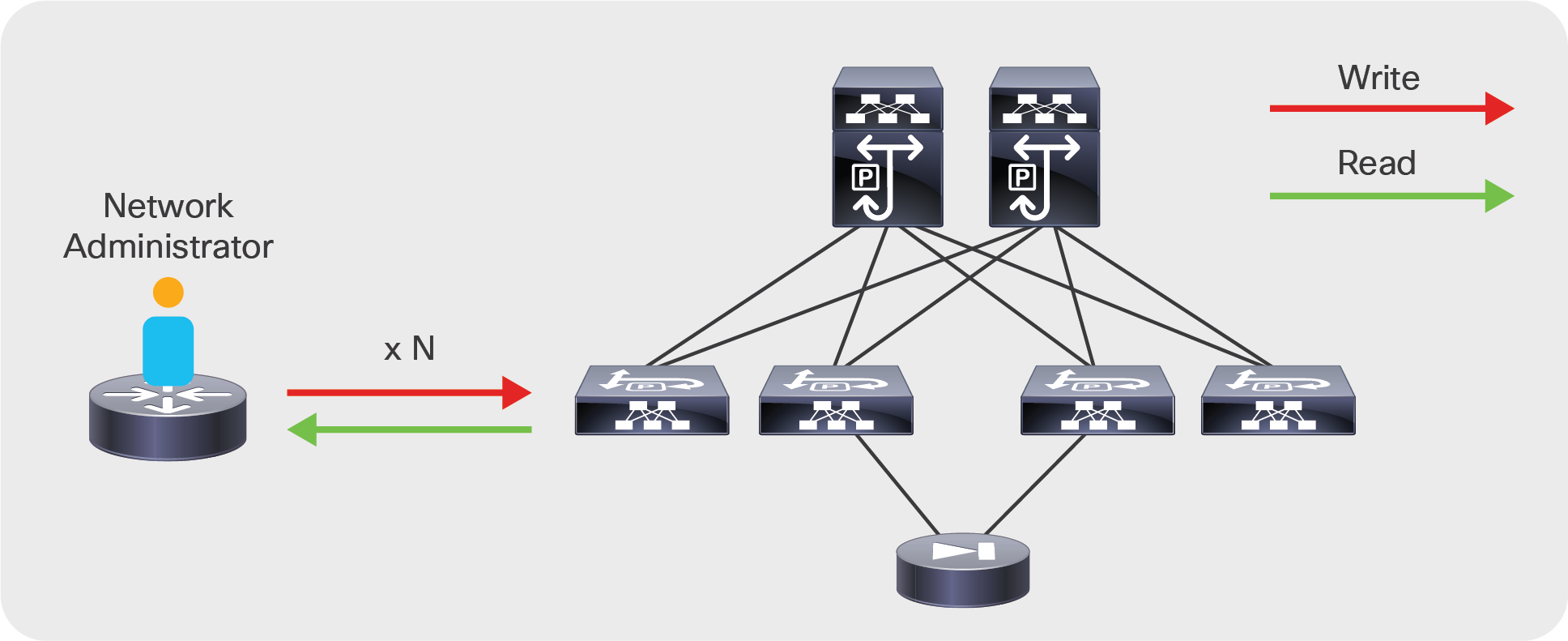
Cisco ACI service graph: the network administrator manages the fabric but not the firewall or load balancer
In addition, with the Cisco ACI service graph, just as with traditional networking, the security administrator can also administer the firewall through a management tool designed for the L4-L7 device (Figure 8) but, differently from classic integration models, with ACI security administrators may be able to define firewall security rules based on EPGs instead of IP addresses or subnets, or they may define security rules based on IPs and be able to see and select IP addresses of servers that are connected to the ACI leaf switches.
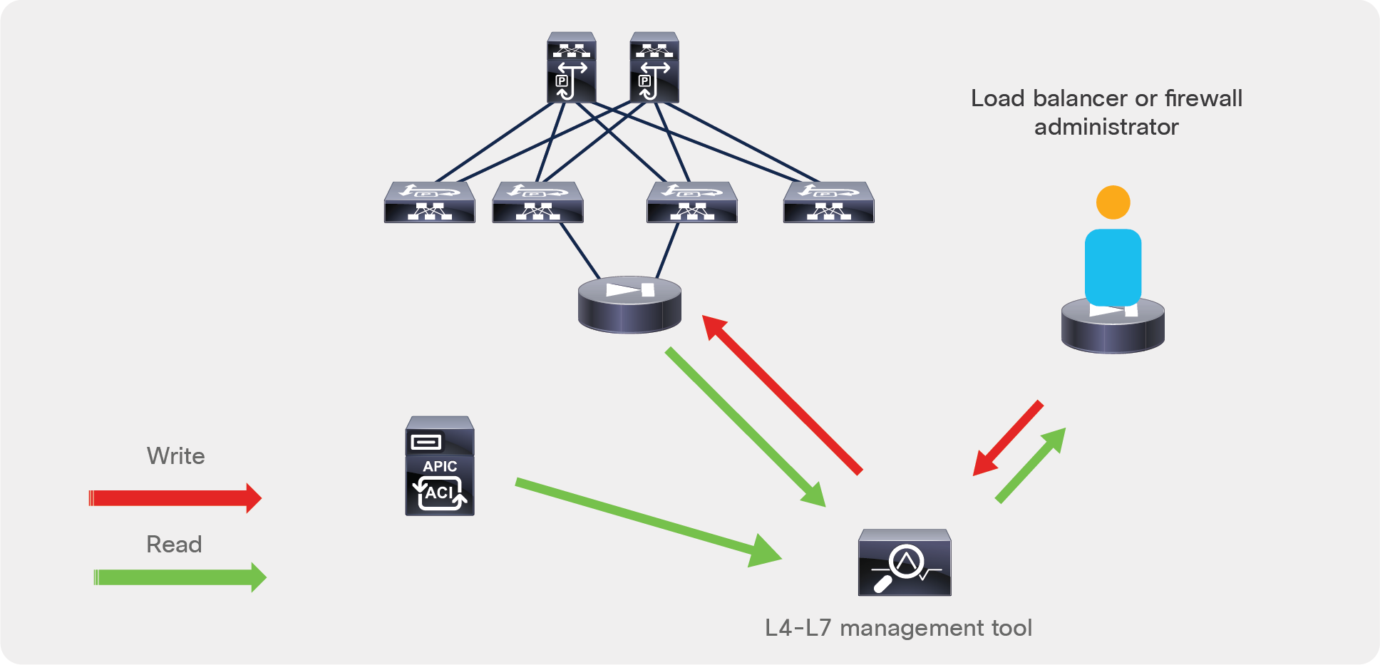
The security administrator can manage the firewall directly or through a management tool and the management tool can interact with APIC REST APIs to retrieve information about endpoint IP addresses and EPGs
This is because many L4-L7 vendors offer an L4-L7 management tool that also connects to the APIC APIs to discover EPGs and endpoints in order to simplify the configuration of ACLs on the firewall or the configuration of load balancing rules on the load balancer.
Design choices for bridge domains, VRF instances, and EPGs
When deploying a service graph, you can choose from the following options:
● Transparent mode: Deploy the L4-L7 device in transparent mode when the L4-L7 device is bridging the two bridge domains. In Cisco ACI, this mode is called Go-Through mode.
● Routed mode: Deploy the L4-L7 device in routed mode when the L4-L7 device is routing between the two bridge domains. In Cisco ACI, this mode is called Go-To mode.
● One-arm mode: Deploy the L4-L7 device in one-arm mode when a load balancer is located on a dedicated bridge domain with one single interface.
● Policy-based redirect (PBR): Deploy the L4-L7 device in inline (L1), transparent (L2), or routed (L3, Go-To) mode and redirect traffic to it based on protocol and port number.
Your first design choice is to identify the number of bridge domains and VRF instances that you need and the number of EPGs and contracts.
Bridge domain and VRF provisioning
Typically, you need to provision one bridge domain for the outside (or client-side or consumer-side) interface, and one bridge domain for the inside (or server-side or provider-side) interface.
Bridge domains have many configurable options. The main choices that you need to make are whether to enable the following:
● Unknown unicast flooding or hardware proxy
● Address Resolution Protocol (ARP) flooding
● Routing
● Subnet IP address
The next section discusses how to tune these options to optimize flooding.
Figure 9 shows a basic setup consisting of two bridge domains with a VRF association. This setup should work for most deployments. This setup uses one EPG for the clients and one EPG for the servers that are associated, respectively, with the outside bridge domain and the inside bridge domain. A VRF instance is allocated to each bridge domain, but it is shown in gray in the figure because it is not really used to route traffic; it is used simply to meet the requirement of the object model for a relationship between a VRF instance and a bridge domain.
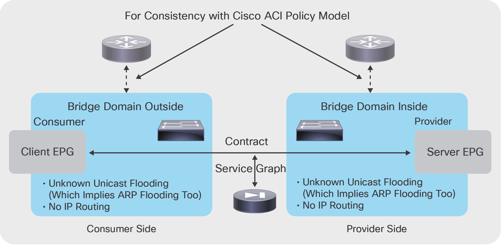
Simple bridge domain setup that works for most deployments
If you deploy the graph with service graph redirect, you need to select one or two bridge domains to which the L4-L7 device connects. Figure 10 shows a design example with service graph redirect with the L4-L7 device connecting to bridge domains that are not used to connect the endpoints. The bridge domains used to connect the L4-L7 device can be the same bridge domains as the consumer and provider endpoints when the service graph is configured for redirect with Go-To mode. The bridge domains for the L4-L7 device need to have data-plane learning disabled on the L4-L7 device interface and gratuitous ARP (GARP) detection enabled.
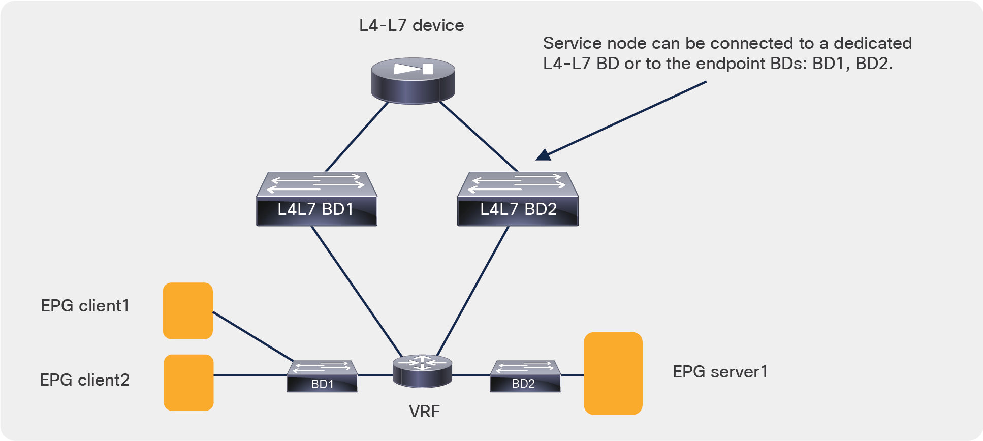
Bridge domain setup for service graph with policy-based redirect (PBR)
Layer 2 and Layer 3 forwarding in Cisco ACI
Cisco ACI forwards traffic by using Virtual Extensible LAN (VXLAN) encapsulation. The way that packets are sent to the VXLAN Tunnel Endpoint (VTEP) at which the destination MAC or IP address is located depends on the bridge domain settings. Cisco ACI can forward traffic based on either the destination MAC address of the packet prior to VXLAN encapsulation or the destination IP address of the packet prior to VXLAN encapsulation.
In Cisco ACI, routed traffic is traffic whose destination MAC address is the router MAC address: that is, the subnet MAC address in the bridge domain. Layer 2, or bridged, traffic is traffic whose destination MAC address is not the router MAC address.
Layer-2 traffic forwarding can be based on the MAC address–to–VTEP mapping learned as a result of flooding along the multicast tree of each bridge domain, or it can be based on the endpoint database that discovers endpoints. The first forwarding mechanism is the classic VXLAN forwarding approach. It is enabled by setting the bridge domain to perform unknown unicast flooding. With the second mechanism, the Layer 2 forwarding of unknown unicast frames is based on the endpoint database, and you need to enable the hardware-proxy option.
Routing traffic is always based on the lookup of the IP address–to–VTEP mapping information. The endpoint IP address is learned through the leaf switch. The leaf switch discovers the endpoint IP address from the ARP requests of the endpoint or from the data-plane traffic from an endpoint that is sending traffic to the destination MAC address of the router.
Note: This behavior can be disabled for the entire VRF (this is a VRF option), or for a specific subnet (this is a BD option), or for a specific IP address, a /32 IP address (this is an EPG option). There is no need for the administrator to use any of these options in case of service graph deployments because IP data-plane learning is automatically disabled on the L4-L7 device interface used for service graph redirect.
When routing is configured on the bridge domain, the bridge domain learns the IP addresses of the endpoints regardless of the subnet to which their IP address belongs. You can and should configure the bridge domain to learn only the IP addresses of the endpoints that belong to the subnet defined in the bridge domain as a default gateway. This option is called Limit IP Learning to Subnet (previously called Subnet Check).
The example in Figure 11 shows where Cisco ACI performs Layer 2 forwarding and where it performs Layer 3 forwarding.
In BD3, the default gateway for the servers is the load balancer; hence, traffic is switched at Layer 2. In BD2, the next hop of the load balancer for outbound traffic is the firewall, and the next hop of the firewall for inbound traffic is the load balancer, so traffic is switched at Layer 2. On BD1, if a subnet is configured in the bridge domain and the default gateway for the firewall is the bridge domain subnet IP address, then traffic is switched at Layer 3.
Note: If Limit IP Learning to Subnet is not enabled on BD1, the endpoint database can learn the IP addresses of the endpoints from BD3 as if they were in BD1.
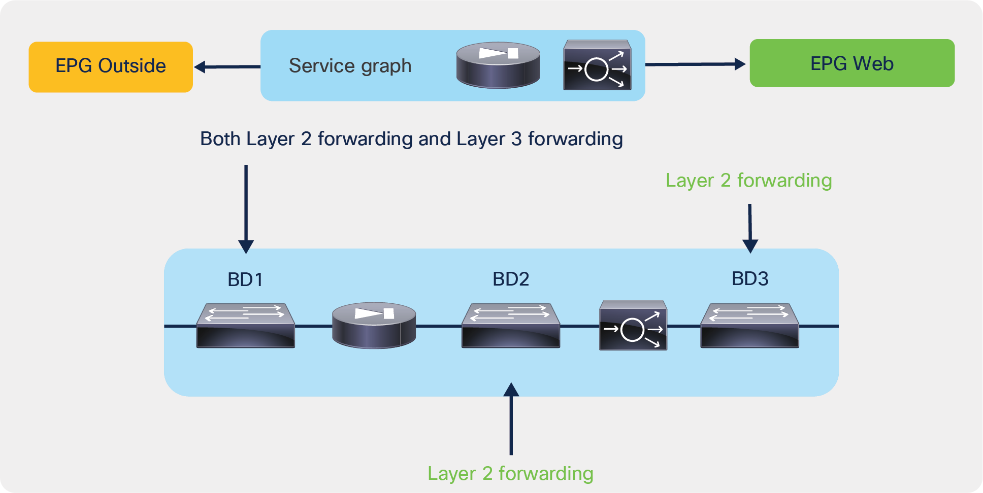
Service graph example showing on which bridge domains Cisco ACI performs Layer 2 and Layer 3 forwarding
Bridge domain tuning considerations
You can tune the bridge domain to reduce the amount of flooding in the domain. Two main options are available to reduce flooding:
● Hardware proxy (instead of unknown unicast flooding): This option forwards bridged unknown unicast MAC addresses to the spine-proxy database. This option provides benefits only in the event of bridged traffic. This option has no influence on routed traffic (that is, traffic in which the destination MAC address is the BD MAC address).
● No ARP flooding: This option transforms broadcast ARP requests into unicast packets. For this feature to work, you need to enable IP routing because the endpoint database must be populated with the IP addresses of the endpoints. Hardware proxy must be enabled too.
In deciding whether to use these features, consider the following:
● Some L4-L7 devices in transparent (Go-Through) mode rely on flooding to build the forwarding tables just as a transparent bridge does.
● When a L4-L7 device fails over, the IP address of that device may or may not change the MAC address too. If it does change the MAC address, the Gratuitous ARP (GARP) traffic generated by the L4-L7 device must reach the ARP cache of the adjacent devices. For this to happen, ARP flooding must be enabled (that is, the ARP flooding optimization option must be off).
If you deploy a service graph in Go-Through mode, Cisco ACI automatically changes the bridge domain settings to enable unknown unicast flooding and ARP flooding. Therefore, if you use a service graph deployment, you can choose whether to optimize flooding only when you are using the Go-To mode.
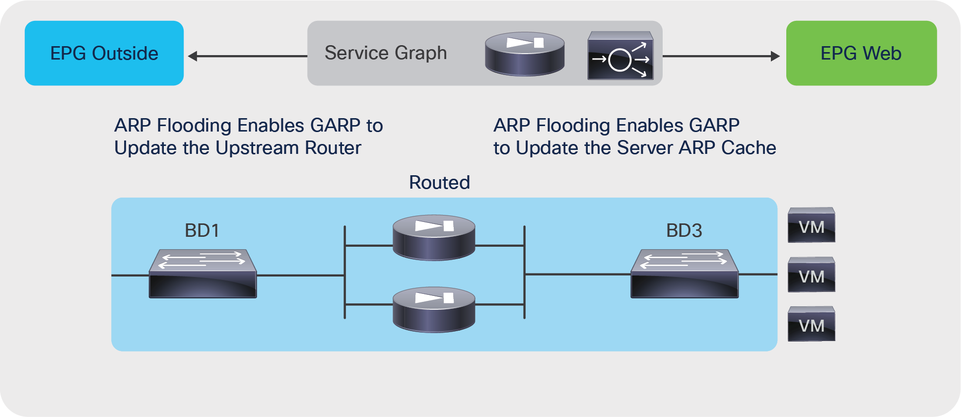
Assuming a service graph deployment with L4-L7 devices in Go-To mode, you also need to consider where flood removal would provide some benefits. Figure 12 illustrates this point. The figure shows a multinode graph. Flooding optimization is useful on BD3 because it has several virtual machines and servers connected to it. The usefulness of flooding optimization on BD1 and BD2 is negligible because BD1 has only the firewall interface and potentially a router interface, and BD2 has only the interfaces of the firewall and the load balancer. Therefore, the only bridge domain for which you may want to optimize flooding is BD3.
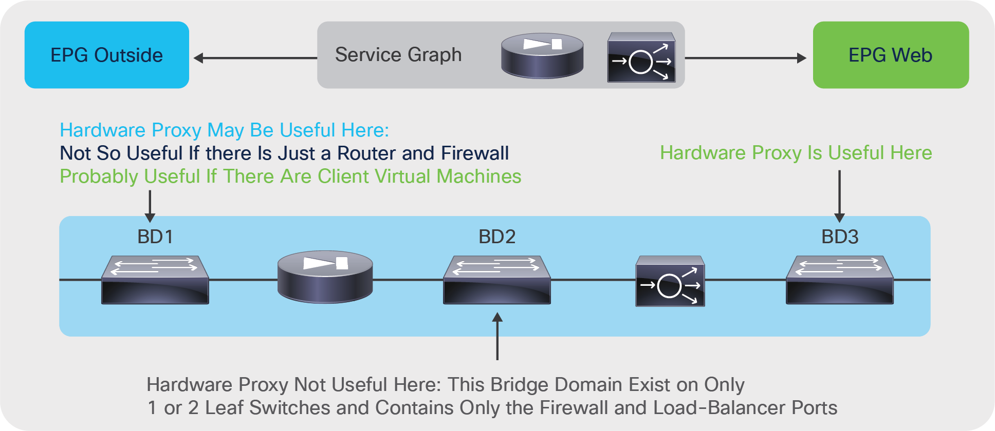
Scenarios in which hardware proxy provides benefits
Figure 13 shows where ARP flooding is needed. With hardware proxy and no ARP flooding, GARP traffic for firewall or load-balancer failover is not flooded. If a service device fails over, the endpoints don’t see the update of the IP address–to–MAC address mapping. This behavior may be acceptable if the L4-L7 device allows you to configure the same MAC address for both L4-L7 devices in the high-availability pair; otherwise, you need to keep ARP flooding enabled.
Tuning ARP flooding
The capability to disable ARP flooding depends on the configuration of hardware proxy and IP routing as follows:
● If hardware proxy is turned off, then ARP flooding is on and cannot be turned off.
● If hardware proxy is turned on but IP routing is turned off, ARP flooding is on and cannot be turned off.
● If hardware proxy is turned on and IP routing is turned on, then you can disable ARP flooding.
You may consider ARP flooding to be necessary because of silent hosts, but this is not completely true. It is true that disabling ARP flooding requires the endpoint database to know the endpoint IP address, and for this IP routing must be turned on. But even if the endpoint had been silent, Cisco ACI can resolve the endpoint IP address by sending ARP messages from the subnet IP address of the bridge domain. This feature is called ARP gleaning, and it requires the bridge domain to be configured with a subnet IP address.
In summary, if you want to reduce ARP flooding (you can’t completely remove it all the time), you need to configure the bridge domain as follows:
● Hardware proxy must be turned on.
● The ARP flooding option must be disabled.
● IP routing must be turned on.
● The subnet IP address must be configured.
● You should use Limit IP Learning to Subnet (previously called Subnet Check).
For most deployments, you should keep ARP flooding on.
Bridge domain tuning for service graph with policy-based redirect (PBR)
When you use service graph redirect, the L4-L7 device can be deployed on a dedicated L4-L7 bridge domain. Therefore, the configuration of the bridge domains to which the virtual machines or the physical servers are connected (BD1 and BD2 in Figure 14) can be performed without having to consider the requirements of the L4-L7 device: in most cases on the bridge domain used for servers you can use hardware proxy, and in certain cases you can also optimize ARP flooding.
The bridge domain that connects to the L4-L7 device must instead be configured as follows:
● IP routing should be enabled.
● Subnet should be configured if the L4-L7 device is deployed in Go-To mode. If instead the L4-L7 device is deployed in L1 or L2 mode, the configuration of a subnet on the bridge domain is not required.
● GARP-based detection should be on.
With Cisco APIC Release 3.0 and earlier, IP data-plane learning had to be disabled on the bridge domain used for the L4-L7 device. Starting from Cisco APIC Release 3.1, data-plane learning is automatically disabled for the shadow EPG for the L4-L7 device interface.
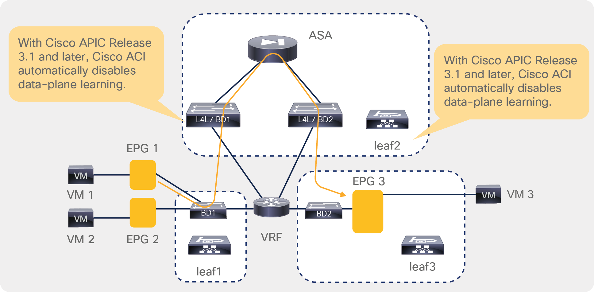
Figure 14 shows why data-plane learning must be disabled for the L4-L7 device interface.
In this example, VM1, EPG1, and BD1 are on Leaf1. The L4-L7 bridge domains and the L4-L7 device are on Leaf2. VM3 is on Leaf3. The redirect policy configured by the APIC administrator says that traffic from EPG1 to EPG3 must go to the firewall.
The endpoint database learns that VM1 is on Leaf1 and that VM3 is on Leaf3 as a result of ARP gleaning or because VM1 and VM3 sent some routed traffic.
VM1 sends traffic to VM3. Cisco ACI redirects this traffic to the firewall. The firewall routes the traffic to L4-L7 BD2. If L4-L7 BD2 was configured like a regular bridge domain, ACI would learn the location of endpoints from routed traffic. In this example, the source IP address of the traffic entering L4-L7 BD2 is the IP address of VM1, and the traffic is routed. Hence, Cisco ACI would normally update the endpoint database to report that VM1 is on Leaf2 instead of Leaf 1. This would be incorrect.
Because data-plane learning is disabled on the internal EPG for the L4-L7 device interface, the traffic forwarded by the firewall doesn't modify the endpoint database.
Why ACI disables data-plane learning on the L4-L7 device connector for service graph redirect
You may need to enable routing on a bridge domain for two main reasons:
● Because you want Cisco ACI to route traffic
● Because you want the endpoint database to hold the IP address information of the endpoints for features such as dynamic endpoint attach or for troubleshooting purposes
Note: Dynamic Endpoint Attach is the feature name that describes the ability for firewall ACLs or ADC load- balanced servers to be dynamically configured when new endpoints are attached to an EPG. This requires north- bound API integration with L4-L7 device management tools. Please see https://dcappcenter.cisco.com/fmc-endpoint-update.html as an example.
Figure 15 illustrates a service graph with a firewall deployed in Go-Through mode, with BD1 providing routing to the outside. To implement this design, you need to enable routing on BD1. In this design, the endpoint database learns the IP addresses of the endpoints attached to BD2 as if they were in BD1. The MAC addresses of the endpoints that are in BD2 are learned on both BD1 and BD2.
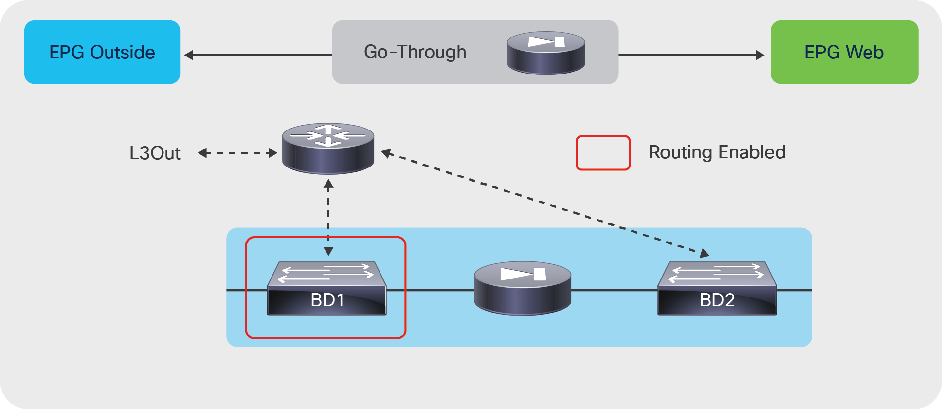
Enabling routing on a bridge domain to route the traffic to the outside
In some designs you also may want to enable routing on the bridge domain to which the servers are attached. You may want to do this not because you want the bridge domain to be the default gateway, but because the endpoint database needs to learn the IP addresses of the servers.
Note: Care should be taken when enabling IP routing on the server-side bridge domain with Go-To or Go-Through service graphs because you could inadvertently provide a direct route from the fabric to the servers, theoretically “bypassing” the L4-L7 device (this is not a problem with the use of policy-based redirect). The section “VRF design considerations for Go-To and Go-Through mode deployments” provides more details.
Figure 16 illustrates this use case.
The endpoint database in BD3 learns the endpoint IP addresses from the ARP requests originated by the hosts. No data-plane learning of the host IP addresses happens because the traffic is destined for the MAC address of the load balancer.
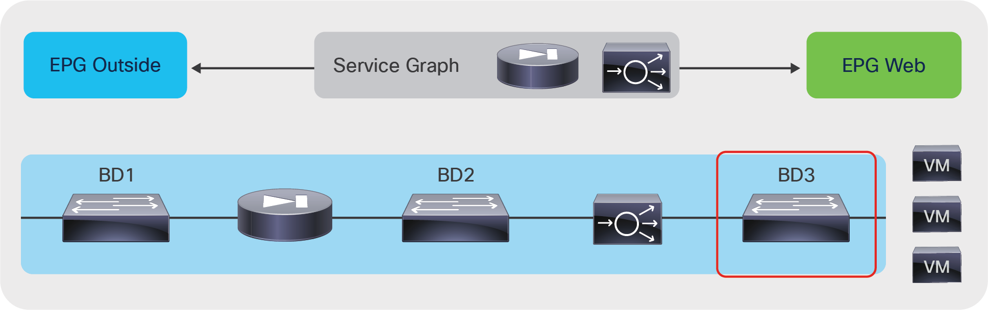
Enabling routing on the server-side bridge domain to use endpoint attachment
When enabling routing, keep in mind that you must enable it in two places in the service graph:
● The bridge domain
● The graph connector
Figure 17 illustrates this point.
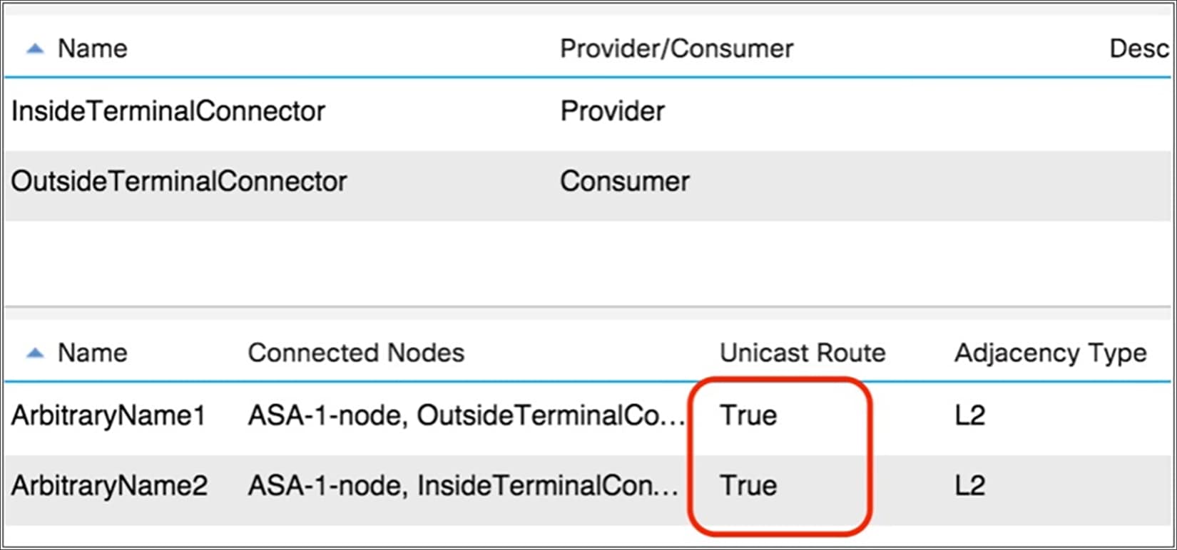
When enabling routing on a bridge domain, make sure that the graph template connectors are set for routing
In general, these connectors are set to unicast routing by default. This setting makes the final state of the bridge domain dependent only on the routing configuration on the bridge domain.
If the connector is associated with a bridge domain that provides the Layer 3 outside (L3Out) interface function, in addition to verifying that the unicast routing option is set to true, you need to make sure that the adjacency is set to Layer 3, not Layer 2, as in Figure 18.
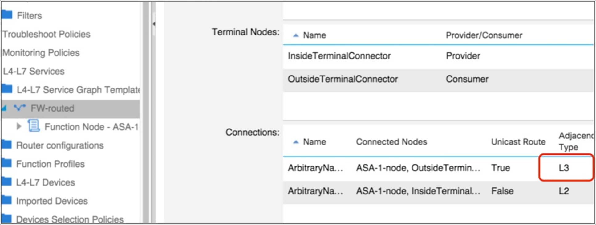
To help ensure that the switch virtual interface is enabled on the bridge domain with L3Out, set adjacency to Layer 3
In summary, IP routing may be necessary in bridge domains that meet the following criteria:
● Bridge domains that provide routing to bridge domains that provide routing to another bridge domain or to the outside
● Bridge domains to which servers are connected, if you plan to use dynamic endpoint attachment
VRF design considerations for Go-To and Go-Through mode deployments
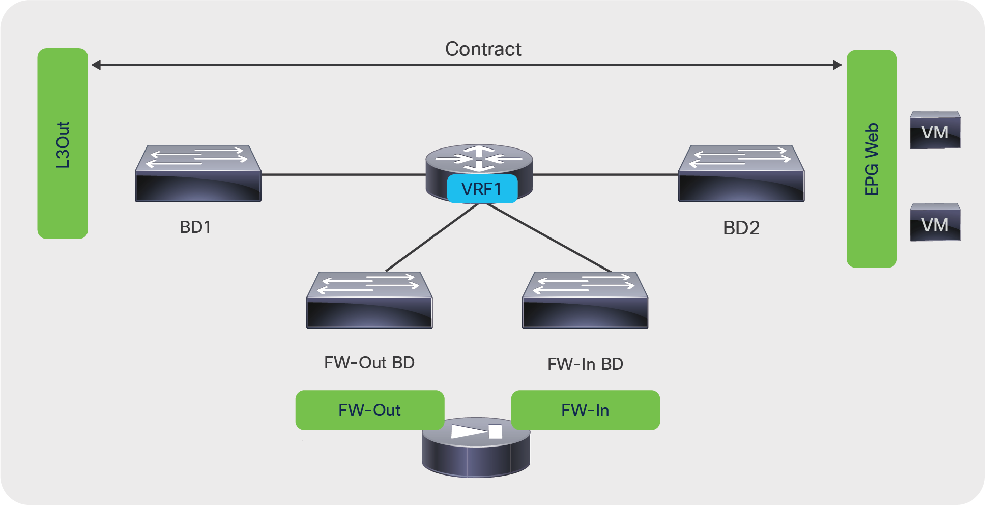
In Cisco ACI, every bridge domain must have a relationship to a VRF instance. The question is whether the same VRF instance can be used for multiple bridge domains, or whether each bridge domain should use a different VRF instance, as illustrated in Figure 19.
As the upper portion of the figure shows, you may have a service graph with two bridge domains associated with the same VRF instance. Alternatively, you may need two separate VRF instances, one for each bridge domain, as in the bottom portion of the figure. The figure shows the VRF instances in gray because they are configured only to meet the object tree requirement to have a VRF instance associated with a bridge domain. However, no bridge domain in this figure is used to route the traffic, so the VRF instance is not doing much from the perspective of the data plane.
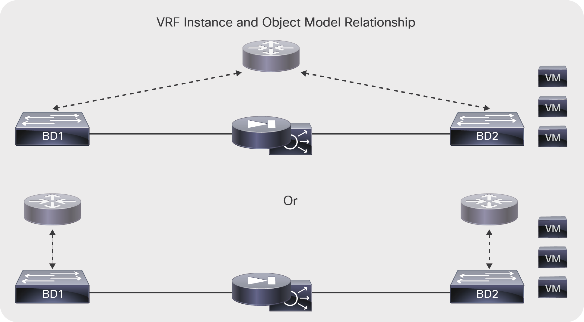
The bridge domain requires a relationship with a VRF instance, and in some designs you may need to allocate one VRF instance per bridge domain
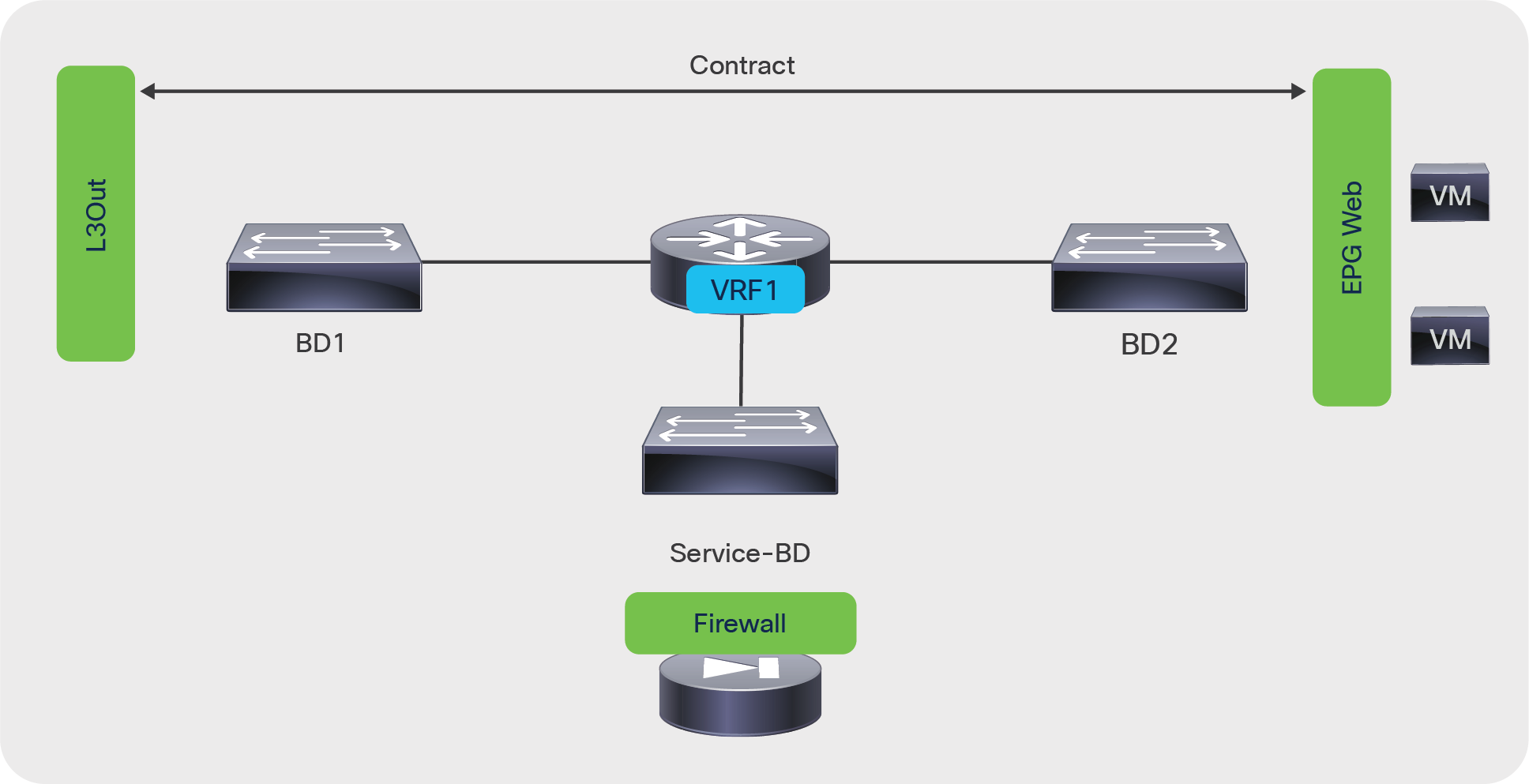
Figure 20 shows a simple design in which a single VRF instance is sufficient, and the instance does not need to be split because IP routing is not enabled for either BD1 or BD2. With this design, the endpoint database is just learning MAC addresses in both bridge domains; hence, traffic entering from BD1 cannot reach BD2 by bypassing the L4-L7 device. No network address translation (NAT) configuration is required on the L4-L7 device.
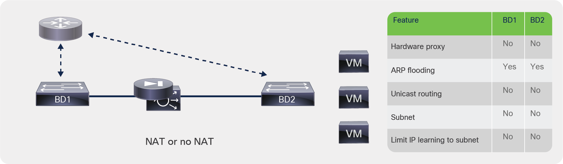
Design using bridge domains without routing
(Note: The VRF instance is shown in gray to indicate that this relationship is needed just to meet object tree requirements.)
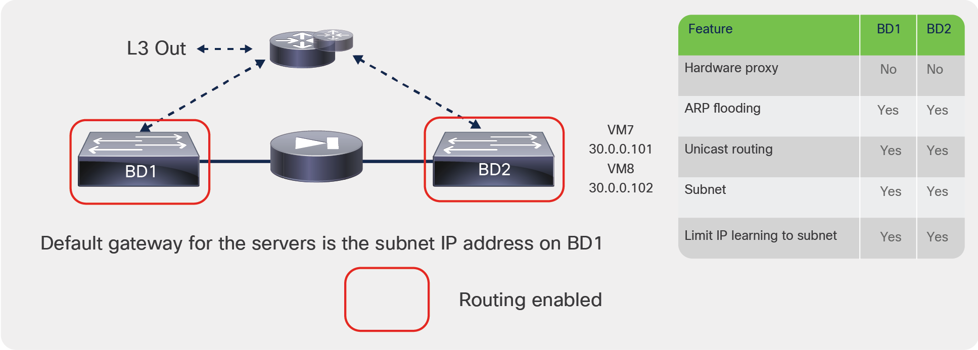
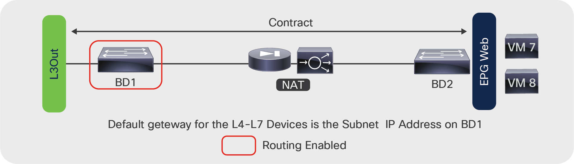
Figure 21 shows another design that doesn’t require two VRF instances. In this case, routing is enabled on BD1 only (hence, the VRF instance is shown in color for the relationship with BD1 and in gray for the relationship with BD2).
There are two possible scenarios to make this design work:
● Limit IP Learning to Subnet is not enabled on BD1: The endpoint IP addresses of the hosts from BD2 are learned on BD1 and associated with the L4-L7 device’s MAC address. In this design, the IP addresses of VM7 and VM8 are learned on BD1 with the MAC address of the firewall or the load balancer. The traffic therefore can be routed to VM7 and VM8. However, this design is not recommended. If you were to enable IP routing on BD2, the endpoint database would be confused because the same IP address could appear on both BD1 and BD2.
● Limit IP Learning to Subnet is enabled, but the L4-L7 device uses NAT: If Limit IP Learning to Subnet is enabled on BD1, the VM7 and VM8 IP addresses are not learned in BD1 (which is desirable). To make sure that the servers are reachable, the L4-L7 device must apply NAT to them so that BD1 learns the NAT addresses of VM7 and VM8. With this design, you can also enable IP routing on BD2, and because of the use of NAT on the L4-L7 device and the Limit IP Learning to Subnet on BD1, the VM7 and VM8 endpoint IP addresses will be learned only in BD2.
(Note: The design in Figure 21 is for explanation purposes only; it is not a design recommendation. Also, the part of the VRF instance associated with BD2 is shown in gray to indicate that this relationship is needed just to meet object tree requirements.)

Design with routing enabled on bridge domain with L4-L7 device in Go-To mode
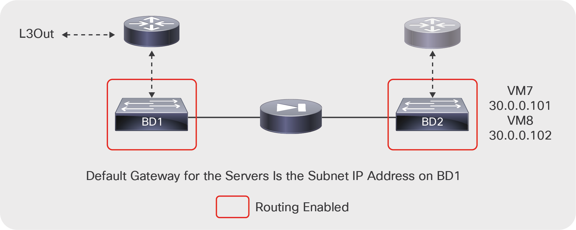
Now imagine a different scenario in which you deploy a transparent device with two bridge domains that are both enabled for routing. This scenario is just theoretical because the service graph wizard will not let you apply a Go-Through graph template to two bridge domains that are both enabled for routing; however, you could potentially design a service insertion topology like this one if you were not using the service graph feature.
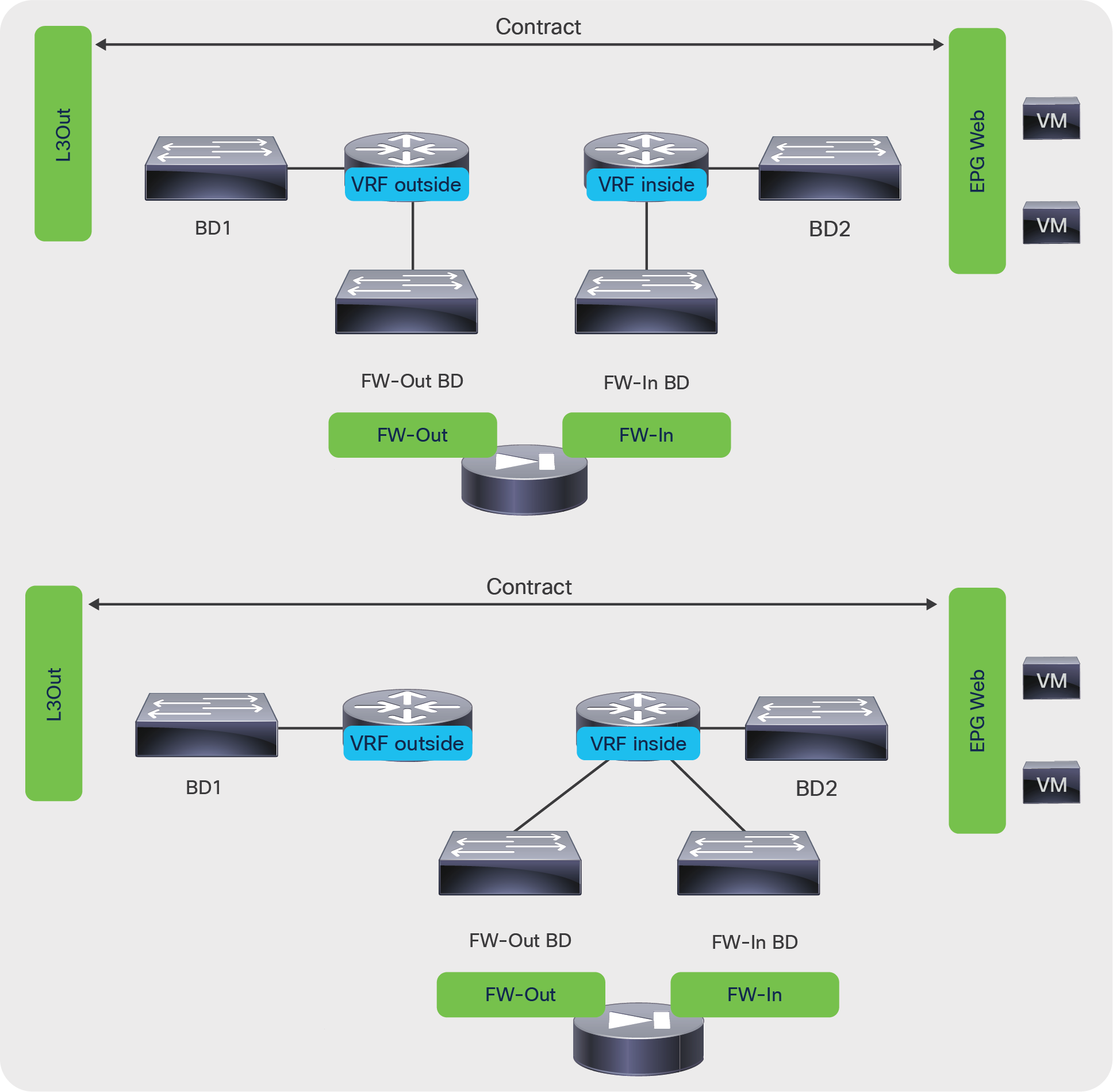
Figure 22 shows BD1 and BD2 both configured for routing. The servers’ default gateway is on BD1; hence, the part of the VRF instance associated with BD1 is shown in color. The subnet IP address on BD2 will not be used by the servers as their default gateway; hence, the part of the VRF instance associated with BD2 is shown in gray.
(Note: The design in Figure 22 is not recommended; it is provided only as an example to explain the need for two VRF instances. Also, the part of the VRF instance associated with BD2 is shown in gray to indicate that this relationship is needed just to meet object tree requirements.)
If routing is enabled in both bridge domains, in some scenarios, such as the one in this figure, you will need to configure two VRF instances
Assuming that you could deploy such a service graph as shown in the preceding example, the endpoint database would be confused, because the same endpoint would appear in two bridge domains for the same VRF instance. In the example in Figure 22, the IP address of VM7 and VM8 would be learned on BD1 and BD2: the routing decision may try to forward traffic directly to BD2, while the service graph contracts would prevent this direct path. For this reason, if you try to deploy a Go-Through service graph with two bridge domains configured for routing, you will receive a fault message, and the graph will not be deployed.
The theoretical solution, provided for educational purposes only, is to create two VRF instances so that each bridge domain has its own address space, as shown in Figure 23.
(Note: The design in Figure 23 is not a design recommendation. Also, the VRF instance associated with BD2 is shown in gray to indicate that this relationship is needed just to meet object tree requirements.)
In this theoretical design, with a Go-Through device placed between two bridge domains that have routing enabled, you would have to create two separate VRF instances to avoid confusing the endpoint database
For this design to work (assuming that the service graph would let you deploy it), you need the following configuration:
● Because the subnet is identical on both bridge domains, you need to provide a different subnet IP address on both bridge domains and change the default MAC address so that the addresses don’t conflict.
● Configure Limit IP learning to subnet even though this will not make much difference because the 30.0.0.x network will exist in both bridge domains
● Define the contracts scope as tenant or global instead of VRF instance.
Figure 24 shows a valid design in which IP routing is enabled on both bridge domains. The L4-L7 device is configured for network address translation (NAT). There is no need to use two separate VRFs because, even if a device were trying to send traffic to the original address of an endpoint in BD2, the service graph contracts would prevent it.
(Note: In Figure 24, the part of the VRF instance associated with BD2 is displayed in gray to indicate that this relationship is needed just to meet object tree requirements.)
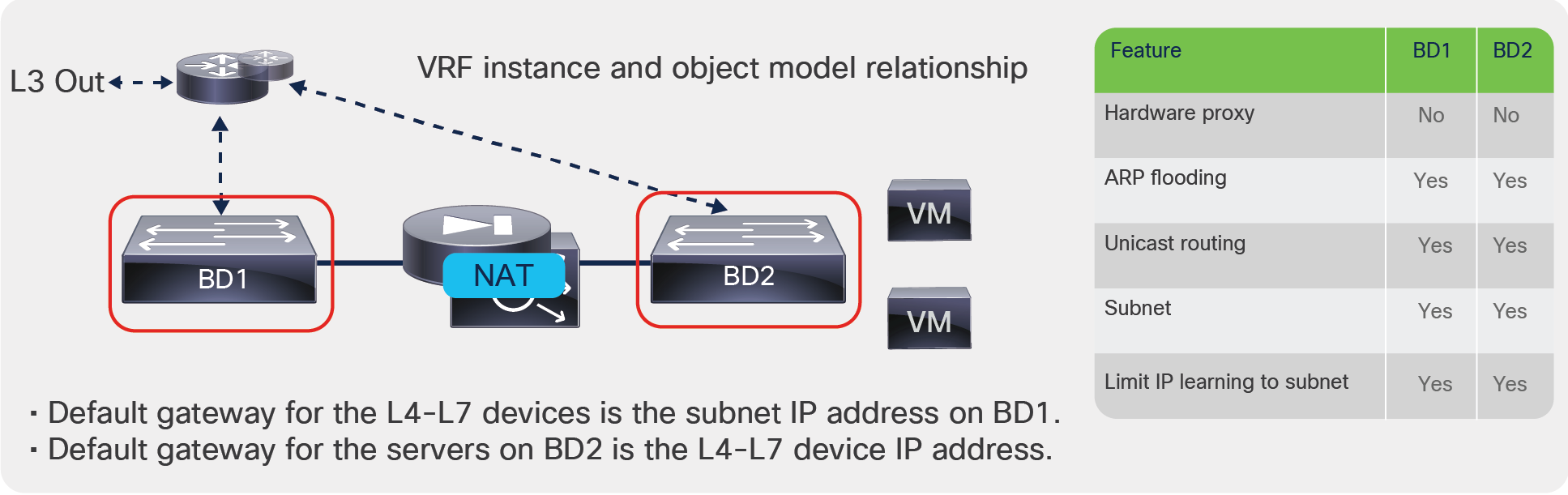
Design with L4-L7 device performing NAT and IP routing enabled on both bridge domains; only one VRF instance Is needed for both bridge domains
In all the designs in which IP routing is enabled on the bridge domain connected to the L4-L7 device as with BD1, Cisco ACI learns the IP address of the endpoints of BD2 associated with the L4-L7 device MAC address on BD1. Two important considerations apply:
● Maximum number of IP addresses per MAC address that are supported: At the time of this writing, Cisco ACI supports a maximum of 4096 IP addresses associated with the same MAC address, so you need to make sure that, with or without NAT, the maximum number of IP addresses learned on BD1 from the L4-L7 device interface stays within this limit.
● Capability for Cisco ACI to age the individual IP addresses: If Cisco ACI learns multiple IP addresses for the same MAC address as in the case of BD1, they are considered to refer to the same endpoint. To help ensure that Cisco ACI ages out each NAT IP address individually, you need to enable an option called IP Aging under Fabric > Access Policies > Global Policies > IP Aging Policy.
In summary, when using designs that require interconnection of multiple bridge domains with IP routing enabled, you should follow these guidelines:
● Enable Limit IP Learning to Subnet to avoid learning the endpoint IP addresses of other bridge domains.
● When using a L4-L7 Go-Through design, do not enable routing on both the bridge domains that the transparent L4-L7 device connects.
● When deploying a L4-L7 device in Go-To mode, you can enable routing on both bridge domains if you perform NAT on the L4-L7 device. With this type of deployment, you should also configure IP aging policy to age the NAT IP addresses individually.
Using L3Out for routing to the L4-L7 device
If you don't use NAT on the L4-L7 device and you want to send traffic whose destination IP address is the endpoint IP address through a firewall or a load balancer, you can use service graph redirect or you need to configure dynamic or static routing to the L4-L7 device through an L3Out connection.
Cisco ACI doesn't let you configure routing on the bridge domain directly. The building block for dynamic and static routing configurations is an L3Out.
An L3Out policy is used to configure the interfaces, protocols, and protocol parameters necessary to provide IP connectivity to external routing devices. An L3Out connection is always associated with a VRF instance. L3Out connections are configured using the External Routed Networks option on the networking menu for a tenant.
Part of the L3Out configuration also involves defining an external network (also known as an external EPG) for the purpose of access list filtering. The external network is used to define the subnets that are potentially accessible through the Layer 3 routed connection.
When using L3Out to route to the L4-L7 device, you normally define a L3Out connection based on the switch virtual interfaces (SVIs) to which the L4-L7 device connects. For this you need to define multiple logical interface profiles with the same encapsulation. The logical interface profiles are the path to the L4-L7 device interface. The path can also consist of a virtual port channel (vPC). Using the same encapsulation, you are creating an external bridge domain that switches traffic between the L3Out connection and the L4-L7 device. You are also helping ensure Layer 2 adjacency between active/standby L4-L7 devices connected to the same L3Out connection with the same encapsulation.
Static and dynamic routing both work on the L3Out SVI with vPC. If you are using static routing, you would also define a secondary IP address as part of the SVI and vPC configuration. The secondary IP address would be used in the L4-L7 static routing configuration as the next hop (Figure 25).
Design with L3Out to the L4-L7 device with SVIs and vPC
The Layer 3 external or external network defined in the L3Out connection is equivalent to an EPG, so you use this to connect the service graph.
With first generation hardware and with Cisco APIC software releases earlier than 2.3, using more than two leaf nodes as part of the same L3Out connection in Cisco ACI had some restrictions. Restrictions used to apply if:
● The L3Out connection consists of more than two leaf nodes with the SVI in the same encapsulation (VLAN).
● The border leaf nodes are configured with static routing to the external device.
● The connectivity from the outside device to the fabric is vPC based.
Figure 26 shows a topology that works with second-generation leaf switches starting with Cisco APIC Release 2.3. This topology works both within a single pod (left) topology as well as with a multi-pod topology (right) (for more information about multi-pod, please refer to: https://www.cisco.com/c/en/us/solutions/collateral/data-center-virtualization/application-centric-infrastructure/white-paper-c11-739571.html).
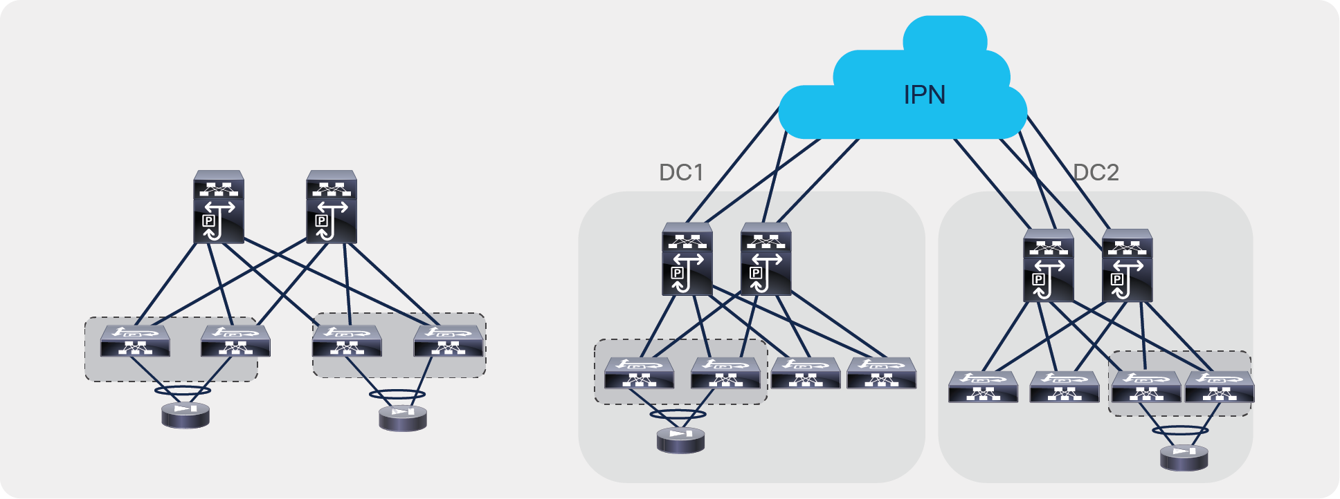
Design considerations with static routing L3Out with SVI and vPC
Note: With topologies consisting of more than two first-generation border leaf switches, the preferred approach is to use dynamic routing and a different VLAN encapsulation per vPC pair on the L3Out SVI. This approach is preferred because the fabric can route the traffic to the L3Out connection that has reachability to the external prefix without the need to perform bridging on an outside bridge domain.
Regardless of which hardware is used on the leaf configured for L3Out, if you are using first-generation leaf switches in the fabric, you also need to consider whether there are servers connected to the same leaf configured for L3Out to an L4-L7 device (Figure 27).
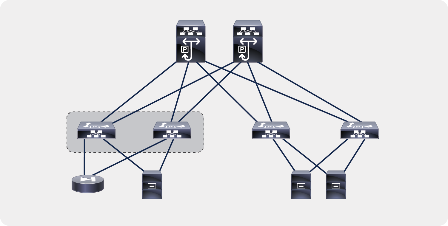
Design considerations when attaching endpoints to leaf nodes configured with L3Out
Attaching endpoints to border leaf switches is fully supported when the leaf switches are all Cisco Nexus 9300 EX and FX platform switches. You should use Cisco ACI Release 2.2(2e), and you should configure System > System Settings > Fabric-Wide Setting Policy by selecting Disable Remote EP Learn. Prior to Cisco ACI Release 3.0(1k), the configuration location was at Fabric > Access Policies > Global Policies > Fabric Wide Setting Policy by selecting Disable Remote EP Learn.
Floating L3Out
When you configure an L3Out to provide connectivity to an L4-L7 device, you must configure the L3Out logical interface path from the border leaf switches to the service device interface, or in the case of virtual appliances, you must specify the uplink of the hypervisor host where a L4-L7 virtual appliance resides. This is not practical because the virtual appliance may move to another hypervisor host.
Starting from the Cisco APIC Release 4.2(1), you must no longer specify multiple L3Out logical interface paths for L3Out SVIs. The new floating L3Out feature enables you to configure an L3Out without specifying logical-interface paths, which makes the configuration simpler. This feature is particularly useful if L4-L7 devices are virtual appliances, which can move to a different hypervisor, whereas physical L4-L7 devices cannot so move unless the cabling is changed.
As of Cisco APIC Release 5.2, service graph doesn’t support using the floating L3Out in the device selection policy. Thus, if you need to configure routing between an L4-L7 device and ACI, and you want to use the floating L3out functionality instead of the regular L3Out, the available option is to connect the L4-L7 device using a floating L3Out without service graph.
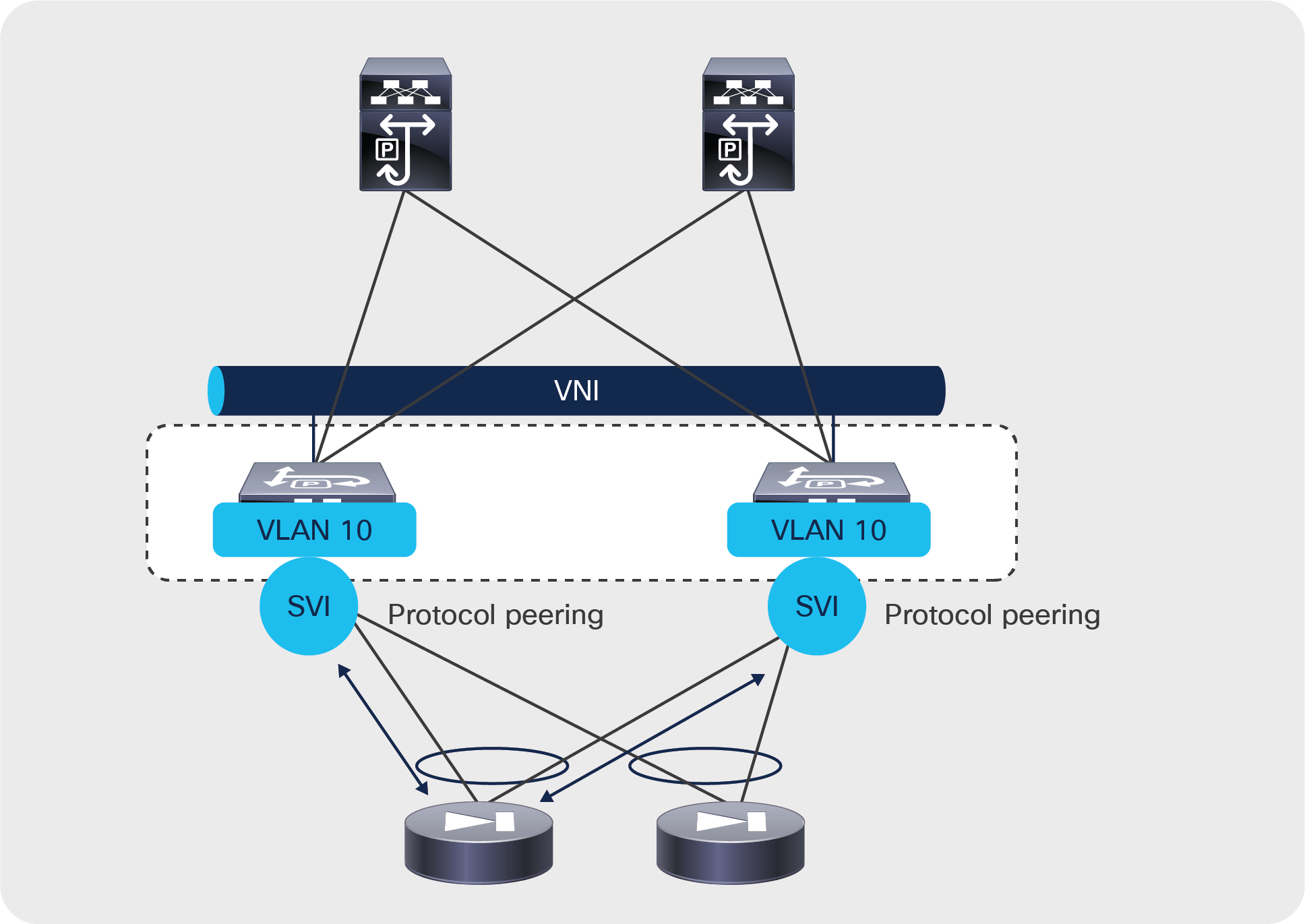
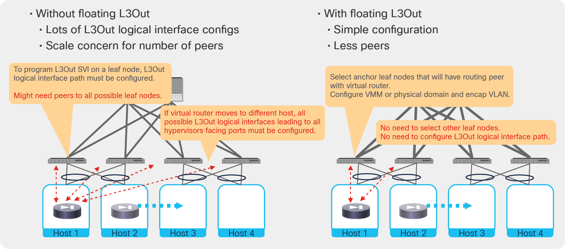
Figure 28 illustrates and compares the configuration of routing between the ACI fabric and an L4-L7 device with a regular L3Out and with a floating L3Out. The floating L3Out feature requires the definition of a pair of leaf switches as anchor leaf nodes, which provide protocol peering with the L4-L7 devices, regardless of which leaf the L4-L7 devices are connected to. From a configuration standpoint this means that, with the floating L3Out, you configure the node profiles only for the anchor leaf switches, and, in the interface profile for the anchor leaf switches, you don’t need to specify a path, only the floating SVI configuration.
The floating L3Out feature defines four types of IP addresses: a primary IP address per anchor leaf switch, a secondary IP address common across the anchor leaf switches (which can be used as a next-hop for static routes defined on L4-L7 devices), a floating primary IP address (used internally by this feature primarily for ARP resolution), a floating secondary IP address (also used internally by this feature for ARP resolution in presence of multiple subnets on the L3Out SVI). Aside from the initial configuration the IP addresses that are relevant to define the configuration between the L4-L7 device and the floating L3Out are the primary and secondary IP addresses of the anchor leaf switches.
Floating L3Out
The following list highlights some of the key configuration points that you need to be aware of to use the floating L3Out:
● Make sure to use the same static VLAN range for both the VMM domain and the external routed domain.
● Configure the node profiles only for the anchor leaf switches and the interface profiles for each anchor leaf only to define the floating SVI, and not to define a path.
● The Floating L3Out functionality is available both as a VMM domain and as part of the physical domain (starting from Cisco APIC Release 5.0(1)).
● The floating L3Out used in conjunction with a VMM domain can be useful for virtual L4-L7 appliances. In this case the floating L3Out is programmed by APIC on the virtual distributed switch as a port group, and you may need to configure the port group (via the APIC GUI under the Floating SVI / Path Attributes configuration) to set promiscuous mode or to allow MAC address changes and/or forged transmits.
● The floating L3Out used in conjunction with a physical domain can be useful, for example, in the following cases: virtual L4-L7 appliances that are used without VMM integration, simpler configuration for the deployment of physical L4-L7 appliances on multiple leaf switches.
● The floating L3Out can be used in conjunction with dynamic routing or static routing.
● When using the floating L3Out to provide the next-hop for static routes defined on L4-L7 devices, you need to configure the secondary IP on the anchor leaf switches and use this IP address as the static route next-hop (and not the floating primary IP address, nor the floating secondary IP).
● You can define up to four anchor leaf switches.
● The floating L3Out can be defined in conjunction with Multi-Pod to define a stretched L3Out across pods.
● By default, traffic from an internal endpoint in the ACI fabric to external network always goes to an anchor leaf node first, because the external route is redistributed into the ACI fabric from the anchor leaf nodes, which could be a suboptimal traffic path. This can be avoided starting from Cisco ACI Release 5.0.
For more information, see https://www.cisco.com/c/en/us/td/docs/switches/datacenter/aci/apic/sw/kb/Cisco-ACI-Floating-L3Out.html.
EPGs, contracts, and connectors
As previously mentioned, the service graph is not attached directly to two bridge domains, but it is associated with a contract that is established between two EPGs, with each EPG is associated with a bridge domain. The example in Figure 29 shows that the service graph is not attached directly to bridge domains but through EPGs.
The service graph is inserted between bridge domains by associating it with EPGs
Device selection policy
When you define a graph template, you define the device type or the sequence of devices that should be placed between the consumer and the provider EPGs.
The graph template abstraction includes the definition of connectors for the graph nodes: that is, for the L4-L7 devices.
In most deployments – for instance, if a firewall is deployed in Go-To mode between two bridge domains (such as bridge domain outside and bridge domain inside) – the bridge domain to which the service graph node connector should be attached is the bridge domain that is associated with the EPG to which the graph itself connects.
In other deployment designs, such as when the device is deployed in one-arm mode or with redirect, the connector can be attached to a different bridge domain than the one in which the provider and consumer connectors are located. The bridge domain to which the service graph is attached can be specified by navigating to Tenant > Services > L4-L7 > Devices Selection Policies > Logical Device Context.
This configuration also tells Cisco ACI where to deploy the shadow EPG.
Graph connector properties
The connector also has two properties: it can be Layer 3 or Layer 2, and you can choose to enable or disable unicast routing on the bridge domain to which it connects.
You can find the connector configuration under Tenant > Services > L4-L7 > Service Graph Templates by selecting a template and then selecting the Policy tab, under Connections.
In most cases, the connector Adjacency Type should be set to Layer 2 (L2) unless you need to bring up the pervasive SVI on a bridge domain that has no endpoints, but in the latest releases this is set to L3 by default because, if there is no SVI present, this setting is simply ignored.
If the connector is set for unicast routing (the option is called Unicast Route), the bridge domain forwarding depends on whether unicast routing is enabled or disabled on the bridge domain itself. If the connector is set to not use unicast routing, then the bridge domain will not perform routing even if the bridge domain is configured for routing.
If you are using the routed mode with an L3Out interface instance, the connector to the outside bridge domain must be configured as Layer 3. You can configure this connector through the GUI by selecting CON1 and changing Adjacency Type from L2 to L3.
You can set the adjacency type through REST calls as follows:
<vnsAbsConnection name = "CON1" adjType=L3>
<vnsRsAbsConnectionConns tDn="uni/tn-Sales/AbsGraph-WebGraph/AbsTermNodeCon-Consumer/AbsTConn" />
<vnsRsAbsConnectionConns tDn="uni/tn-Sales/AbsGraph-WebGraph/AbsNode-Virtual-Server/AbsFConn-external" />
</vnsAbsConnection>
Deploying the graph template on multiple EPG pairs
The service graph is always associated with a contract between two EPGs.
An L4-L7 device can be connected through a service graph to multiple EPGs. Because the interfaces of the L4-L7 devices are the same, Cisco ACI allocates a different VLAN for the L4-L7 interface and the associated shadow EPG each time the consumer-side or provider-side EPG is in a different bridge domain.
Figure 30 illustrates this point. In this figure, the graph template is applied one time between the EPG Outside and the EPG Web, and it is applied a second time between the EPG Outside and EPG App. The EPG Web and EPG App are in the same bridge domain; hence, the L4-L7 appliance interfaces are associated with two shadow EPGs: one for BD1 and one for BD2.
Even if the graph template is applied to more EPGs in BD1 or BD2, the L4-L7 appliance is still connected only to the two shadow EPGs.
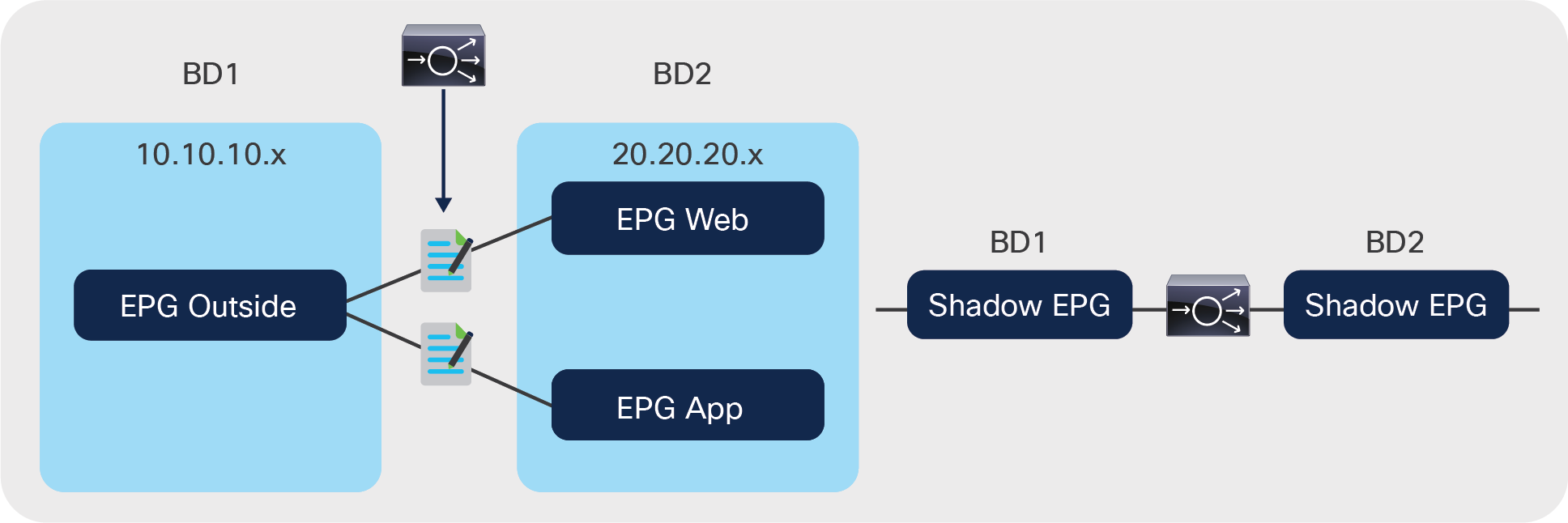
When the service graph is used between multiple EPGs on two bridge domains, the L4-L7 appliance always is attached to two shadow EPGs
If the graph template is applied to EPGs in different bridge domains, Cisco ACI will configure more shadow EPGs (one per bridge domain), as shown in Figure 31.
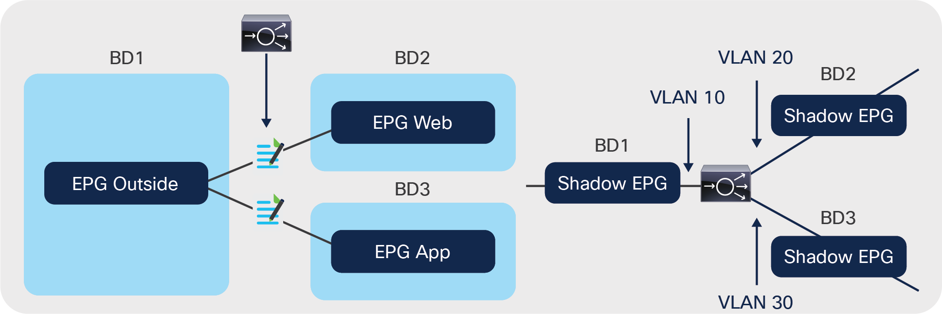
When the service graph is used between multiple EPGs in three bridge domains, the L4-L7 appliance is attached to three shadow EPGs
With an L4-L7 deployment with virtual appliances, Cisco ACI assigns the VLAN to the port group that the L4-L7 device interface attaches to (hence also to the shadow EPGs), making sure that they match.
The following configuration illustrates the device selection policy (logical device contexts) for the configuration of a virtual L4-L7 device via VMM integration.
Assume that you had defined these logical interfaces:
<vnsLDevVip name="ASAv01-cluster">
<vnsCDev name="ASAv01-active" vmName="ASAv01" vcenterName="line1" >
<vnsCIf name="Gig0/0" vnicName="Network adapter 2"/>
<vnsCIf name="Gig0/1" vnicName="Network adapter 3"/>
<vnsCIf name="Gig0/2" vnicName="Network adapter 4"/>
</vnsCDev>
<vnsLIf name="external">
<vnsRsCIfAtt tDn="uni/tn-TenantName/lDevVip-ASAv01-cluster/cDev-ASAv01-active/cIf-[Gig0/0]"/>
</vnsLIf>
<vnsLIf name="internal">
<vnsRsCIfAtt tDn="uni/tn-TenantName/lDevVip-ASAv01-cluster/cDev-ASAv01-active/cIf-[Gig0/1]"/>
</vnsLIf>
<vnsLIf name="internal2">
<vnsRsCIfAtt tDn="uni/tn-TenantName/lDevVip-ASAv01-cluster/cDev-ASAv01-active/cIf-[Gig0/2]"/>
</vnsLIf>
Assume that you defined three contracts as in the following XML script:
<vzBrCP name="c1">
<vzSubj name="http">
<vzRsSubjGraphAtt tnVnsAbsGraphName="g1"/>
</vzSubj>
</vzBrCP>
<vzBrCP name="c2">
<vzSubj name="http">
<vzRsSubjGraphAtt tnVnsAbsGraphName="g1"/>
</vzSubj>
</vzBrCP>
You can then define a logical device selection policy, like the one shown here, which selects the same outside interface and bridge domain for each contract (c1, c2), but a different inside interface and bridge domain for each contract:
<vnsLDevCtx ctrctNameOrLbl="c1" graphNameOrLbl="any" nodeNameOrLbl="any">
<vnsRsLDevCtxToLDev tDn="uni/tn-TenantName/lDevVip-ASAv01-cluster"/>
<vnsLIfCtx connNameOrLbl="external">
<vnsRsLIfCtxToLIf tDn="uni/tn-TenantName/lDevVip-ASAv01-cluster/lIf-external"/>
<vnsRsLIfCtxToBD tDn="uni/tn-TenantName/BD-consBD1"/>
</vnsLIfCtx>
<vnsLIfCtx connNameOrLbl="internal">
<vnsRsLIfCtxToLIf tDn="uni/tn-TenantName/lDevVip-ASAv01-cluster/lIf-internal"/>
<vnsRsLIfCtxToBD tDn="uni/tn-TenantName/BD-provBD1"/>
</vnsLIfCtx>
</vnsLDevCtx>
<vnsLDevCtx ctrctNameOrLbl="c2" graphNameOrLbl="any" nodeNameOrLbl="any">
<vnsRsLDevCtxToLDev tDn="uni/tn-TenantName/lDevVip-ASAv01-cluster"/>
<vnsLIfCtx connNameOrLbl="external">
<vnsRsLIfCtxToLIf tDn="uni/tn-TenantName/lDevVip-ASAv01-cluster/lIf-external"/>
<vnsRsLIfCtxToBD tDn="uni/tn-TenantName/BD-consBD1"/>
</vnsLIfCtx>
<vnsLIfCtx connNameOrLbl="internal">
<vnsRsLIfCtxToLIf tDn="uni/tn-TenantName/lDevVip-ASAv01-cluster/lIf-internal2"/>
<vnsRsLIfCtxToBD tDn="uni/tn-TenantName/BD-provBD2"/>
</vnsLIfCtx>
</vnsLDevCtx>
Cisco ACI supports these deployment modes for L4-L7 devices with the service graph:
● Go-To mode (also known as routed mode): In this mode, the default gateway for the servers is the L4-L7 device.
● Service graph redirect with a L4-L7 device in Go-To (routed), L1 or L2 mode: In this mode, the default gateway for the servers is the Cisco ACI bridge domain, and traffic is sent to the L4-L7 device based on the contract configuration between EPGs. Service graph redirect is the preferred deployment mode for the service graph when Cisco Nexus 9300 EX and FX platform switches are used.
● Go-Through mode (also known as transparent mode or bridged mode): In this mode, the default gateway for the servers is the client-side bridge domain, and the L4-L7 device bridges the client-side bridge domain and the server-side bridge domain.
● One-arm mode: in this mode, the default gateway for the servers is the server-side bridge domain, and the L4-L7 device is configured for source NAT (SNAT).
The simplest way to deploy a service graph in routed mode is to use NAT on the L4-L7 device. Cisco ACI also supports service devices deployed in routed mode with either static or dynamic routing by connecting the L4-L7 device to an L3Out as described in the section “Using L3Out for routing to the L4-L7 device.”
The routed mode design with NAT or with an external router requires two bridge domains: one for the client-side, or outside, interface; and one for the server-side, or inside, interface. The default gateway for the servers is the service appliance internal or server-side interface IP address.
The routing from the outside (clients) to the service device to the inside (servers) can be provided by the fabric itself (through a VRF instance) or by an external router.
This document divides the routed mode designs into these categories:
● Routed mode with outside Layer 2 bridge domain: In this design, the outside of the service graph connects to a Layer 2 bridge domain. The routing to the service device is implemented with an external routing device.
● Routed mode with NAT: This design can be implemented if the service device implements NAT, as in the case of a load balancer or in the case of a firewall that is translating the internal IP addresses. In this design, the service graph connects to the outside network through routing provided by the Cisco ACI fabric via an L3Out.
● Routed mode in which the L3Out interface performs Layer 3 peering with the L4-L7 device: In this design, the L4-L7 device doesn’t use NAT to translate the addresses of the servers. Therefore, you need to configure static or dynamic routing on the L3Out interface with the L4-L7 device.
● Routed mode with policy-based redirect (PBR) to the L4-L7 device: In this design, you don’t need NAT on the L4-L7 device nor an L3Out to route traffic to the L4-L7 device. The Cisco ACI fabric redirects traffic to the L4-L7 device based on contracts.
Routed mode with outside Layer 2 bridge domain
In this design, the L4-L7 service may or may not be configured to translate the IP addresses of the servers, as may be the case with a firewall configuration (Figure 32). In addition, in this design you use an external router to provide the default gateway to the service device.
Topology of a firewall deployed in routed mode
Figure 32 shows a design in which both the outside and the inside bridge domains are Layer 2 only. Bridge domains can be tuned for flood reduction, which can be useful for BD2.
In the case in the figure, the service graph template is associated with a contract between a client-side EPG and a server-side EPG.
The L4-L7 device provides the default gateway for the servers.
Routed mode with NAT on the L4-L7 device
If the service device uses NAT to translate the IP addresses of the servers, as in the case of a load balancer, you can choose to use an L3Out from the fabric to provide routing from the outside interface to the service device (Figure 33).
Topology of a load balancer deployed in routed mode with L3Out
Figure 33 shows a design in which the load balancer is placed between an L3Out instance and the servers. The internal bridge domain (BD2) doesn’t offer any routing for the servers.
The L4-L7 device provides the default gateway for the servers.
The routing on the L4-L7 device uses static routes pointing to the subnet of the outside bridge domain.
The outside bridge domain in this figure offers routing for the service appliance. The subnet address of the outside bridge domain is the default gateway of the service appliance, and the L4-L7 appliance NAT range belongs to this bridge domain subnet (or an additional subnet on this bridge domain).
Because BD1 has routing enabled, you need to make sure that BD1 learns only the NAT addresses of the virtual machines by configuring Limit IP Learning to Subnet (which was previously called Subnet Check). You also need to make sure that a maximum of 4096 IP addresses are learned on this interface (based on the verified scalability limits – see Numbers of IPs per MAC in https://www.cisco.com/c/en/us/support/cloud-systems-management/application-policy-infrastructure-controller-apic/tsd-products-support-series-home.html#Verified_Scalability_Guides), and that the IP addresses are aged independently by configuring IP aging.
In the case of this design, the service graph template is associated with a contract between the L3Out EPG (L3InstP) and the server EPG.
Routed mode with L3Out routing to the L4-L7 device
This design consists of two VRF instances: one to provide route peering with the outside of the Cisco ACI fabric and to the outside or client-side interface of a firewall or a load balancer, and another for the server farm. Note that you don’t need to use two bridge domains for this design; you can have only one for the servers.
The bridge domain doesn’t need to be configured for routing. The server default gateway then would be the L4-L7 device.
Figure 34 illustrates this design.
Topology of a routed L4-L7 deployment with static or dynamic routing to the L4-L7 device
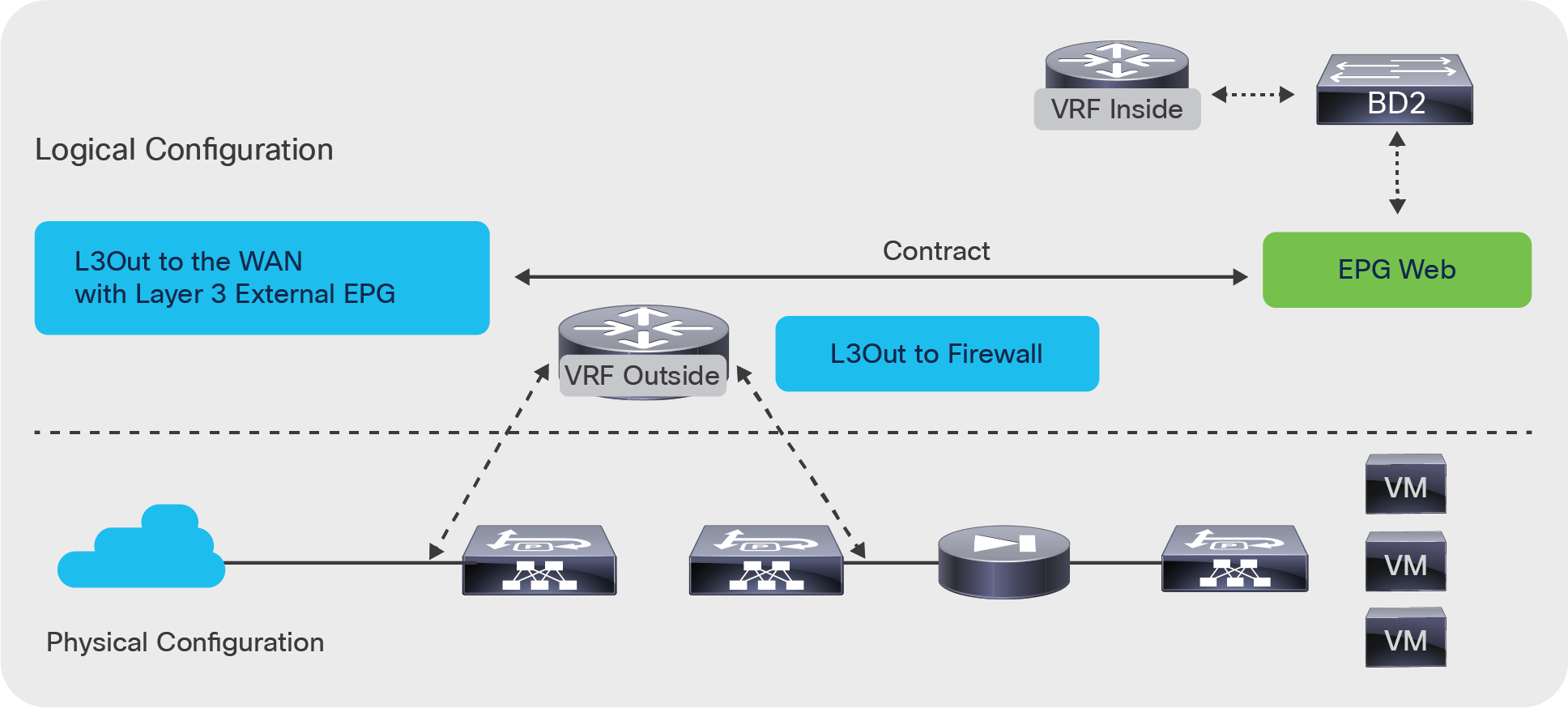
The VRF outside instance has two L3Out interfaces: one configured for routing to the WAN, and one configured for routing to the firewall. The contract for this service graph is established between the L3Out interface to the WAN and the server EPG. The consumer connector of the service graph is configured to be associated with the L3Out external network (L3 external).
The outside connector of the service graph must also be configured for adjacency type Layer 3 and for unicast routing.
You can find the connector configuration under Tenant > Services > L4-L7 > Service Graph Templates by selecting a template and then selecting the Policy tab, under Connections.
In this design, you may want to tune BD2 to reduce flooding.
If the active/standby L4-L7 device pair is connected to first-generation leaf switches, or, more generally, if the fabric includes both first-generation leaf switches, there are additional design considerations related to vPC and L3Outs, which are described in the section "Using L3Out for routing to the L4L7 device."
PBR to the L4-L7 device (with the device in routed mode or L1/L2 mode)
Another deployment model you can use is policy-based redirect. PBR requires the use of a service graph, and the PBR node must be in Go-To, L,1 or L2 mode.
Unlike the previous design options, PBR doesn’t require an L3Out for the service node, two VRF instances, or NAT. Using PBR, the Cisco ACI fabric can route traffic to the service node based on the source EPG, the destination EPG, and contract filter matching. The bridge domain needs to be configured for routing. The server default gateway and service node (PBR node) gateway must be a Cisco ACI fabric bridge domain subnet (Figure 35).
Topology of a routed L4-L7 deployment with PBR to the L4-L7 device
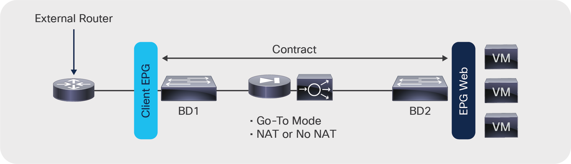
In the example shown in Figure 35, the PBR node has two interfaces: one configured for the consumer side and one configured for the provider side, but it is also possible to deploy PBR with a one-arm type of design if the L4-L7 device is configured for routed mode (Figure 36).
In the example shown in Figure 35, the L4-L7 device is connected to two service bridge domains. Starting from Cisco APIC Release 3.1, with the L4-L7 device in Go-To mode with second-generation leaf nodes, there is no requirement to configure a service bridge domain, and the L4-L7 device could be connected directly in BD1 or BD2.
As Figure 36 illustrates, PBR can be used in a one-arm mode deployment as well if the L4-L7 device is deployed in Go-To mode
Note: For one-arm deployments make sure that your firewall allows traffic to be routed in and out of the same security zone interface.
Topology of a routed L4-L7 deployment with PBR one-arm mode
PBR also can be used in a two-VRF-instances design with route leaking. You can place a PBR device between consumer and provider VRF instances or in either of them, as in Figure 37.
Topology of a routed L4-L7 deployment with PBR in two VRF instances
Starting from Cisco ACI Release 5.2, the Go-To mode PBR device interface can be in an L3Out instead of a BD.
For more information about PBR, see the Cisco Application Centric Infrastructure Policy-Based Redirect Service Graph Design White Paper at https://www.cisco.com/c/en/us/solutions/collateral/data-center-virtualization/application-centric-infrastructure/white-paper-c11-739971.html.
Transparent mode (Go-Through mode)
The deployment of the L4-L7 device in transparent mode (also referred to as Go-Through mode) requires two bridge domains. The service device doesn’t provide the default gateway for the servers. The servers’ default gateway is either the subnet on the outside bridge domain or an external router. The routing from the outside (clients) to the inside (servers) interfaces can be provided by the fabric itself (through a VRF instance) or by an external router.
With Go-Through mode, Cisco ACI doesn’t let you configure IP routing on both bridge domains, and even if you configure hardware proxy, Cisco ACI will set the bridge domain for unknown unicast flooding and ARP flooding.
This document divides the transparent mode designs into two categories:
● Transparent mode with outside Layer 2 bridge domain: In this design, the outside of the service graph connects to a Layer 2 bridge domain. The routing to the service device is implemented with an external routing device.
● Transparent mode with L3Out: In this design, the service graph connects to the outside network through routing provided by the Cisco ACI fabric.
Transparent mode with outside Layer 2 bridge domain
Figure 38 shows a transparent mode deployment with routing provided by an external router.
The design requires two bridge domains. The default gateway for the servers is the IP address of the external router. Tuning the bridge domains for flooding reduction is not possible because the service graph ensures that Layer 2 unknown unicast flooding is enabled.
Firewall deployed in transparent mode with routing outside the fabric
Figure 39 shows a transparent mode deployment with routing provided by the Cisco ACI fabric.
This design requires two bridge domains. The default gateway for the servers is the IP address of the subnet of the outside bridge domain. Because IP routing is enabled on BD1, the IP addresses of the endpoints in BD2 are learned as if they were in BD1, and they are associated with the MAC address of the L4-L7 device.
Because BD1 has routing enabled, you need to make sure that BD1 learns only the addresses of the subnet that you defined. Thus, you should configure Limit IP Learning to Subnet (previously called Subnet Check). You also need to make sure that a maximum of 4096 IP addresses are learned on this interface (based on the verified scalability limits), and that the IP addresses are aged independently by configuring IP aging.

Firewall deployed in transparent mode with routing provided by the Cisco ACI fabric
Figure 40 shows a one-arm mode deployment with the classic networking constructs. Figure 41 shows the same topology in Cisco ACI.
In one-arm mode, the default gateway for the servers is the router and not the load balancer. The load balancer is connected with one VLAN to the router as well, which is the default gateway for the load balancer itself. The load balancer uses source NAT for the traffic from the clients to the servers to help ensure receipt of the return traffic.
With ACI the routing is performed by the ACI fabric, the default gateway for the servers is the subnet on BD2, and the default gateway for the load balancer is the subnet on BD3.
The contract is established between the external EPG and the server EPG, and is associated with the service graph.
This topology has three bridge domains: one bridge domain for the outside, or client side (BD1); one bridge domain for the inside, or server side (BD2); and one bridge domain for connectivity with the load balancer (BD3). With this setup, you can optimize flooding on BD2.
On BD3 the load balancer forwards traffic from the clients to the servers by routing it through the Cisco ACI fabric. Therefore, you need to make sure that the only addresses learned in BD3 are the ones that belong to the BD3 subnet: that is, the virtual addresses announced by the load balancer and the NAT addresses.
You should configure Limit IP Learning to Subnet (previously called Subnet Check) on BD3. You also need to make sure that a maximum of 4096 IP addresses are learned on this interface (based on the verified scalability limits) and that the IP addresses are aged independently by configuring IP aging.
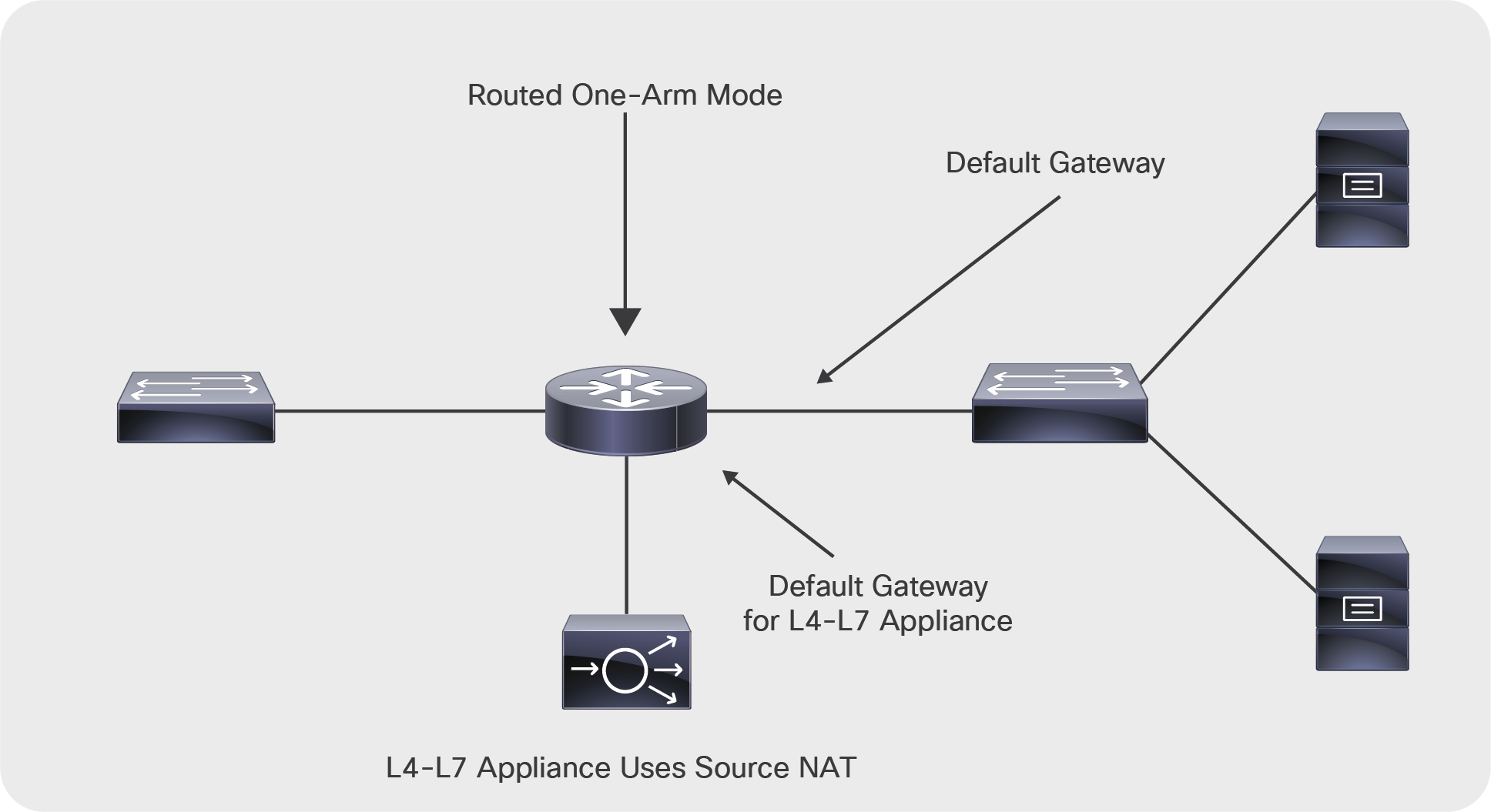
Deployment of a load balancer in one-arm mode
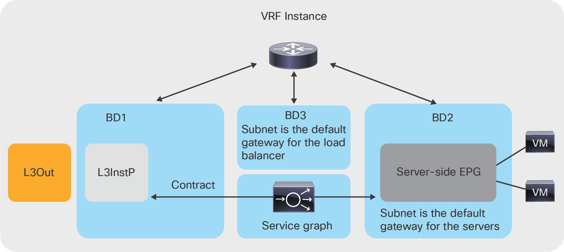
Load balancer deployed in one-arm mode in Cisco ACI
The service graph design needs to take into account three types of traffic:
● Management traffic
● Data traffic
● Failover traffic between service nodes (if service-node high availability is needed)
This section describes the topology choices for these different traffic types (Figure 42).
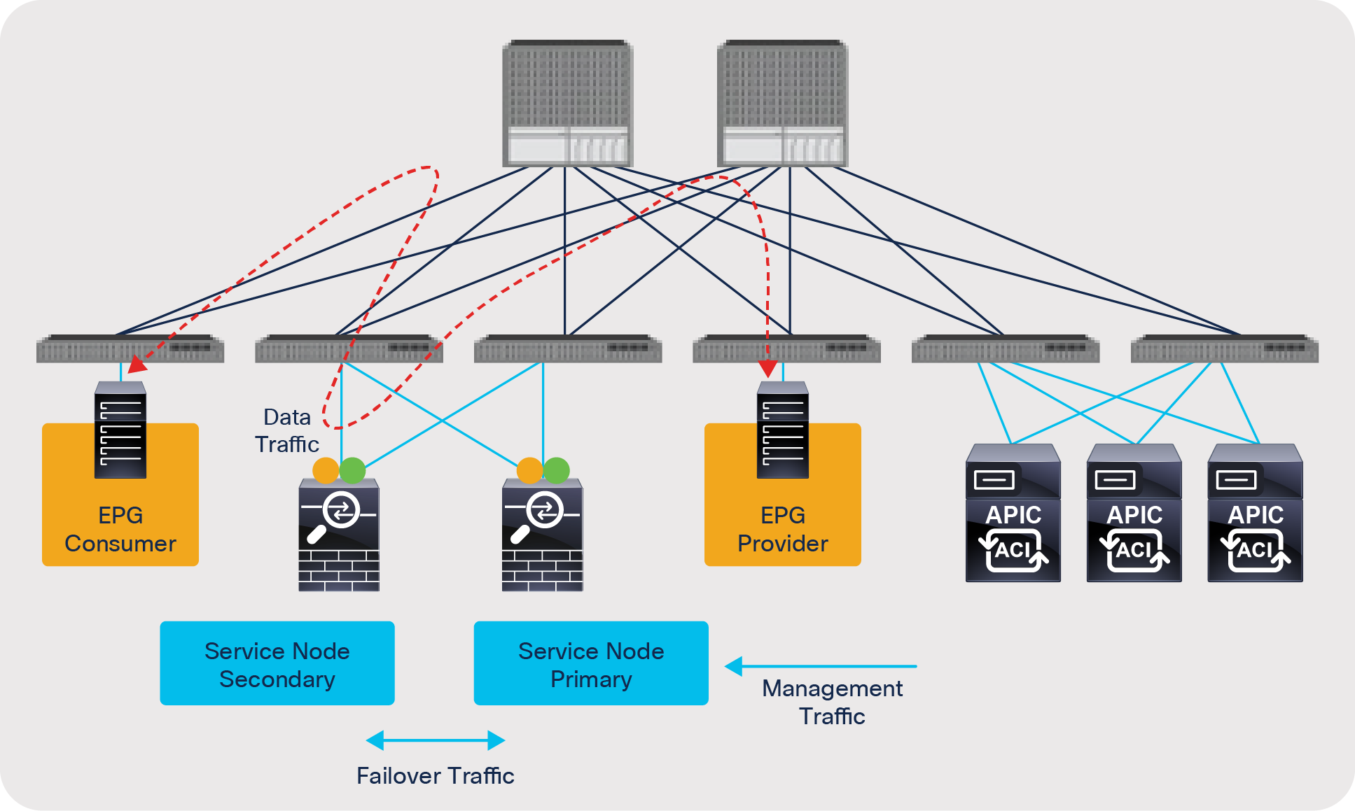
Physical topology
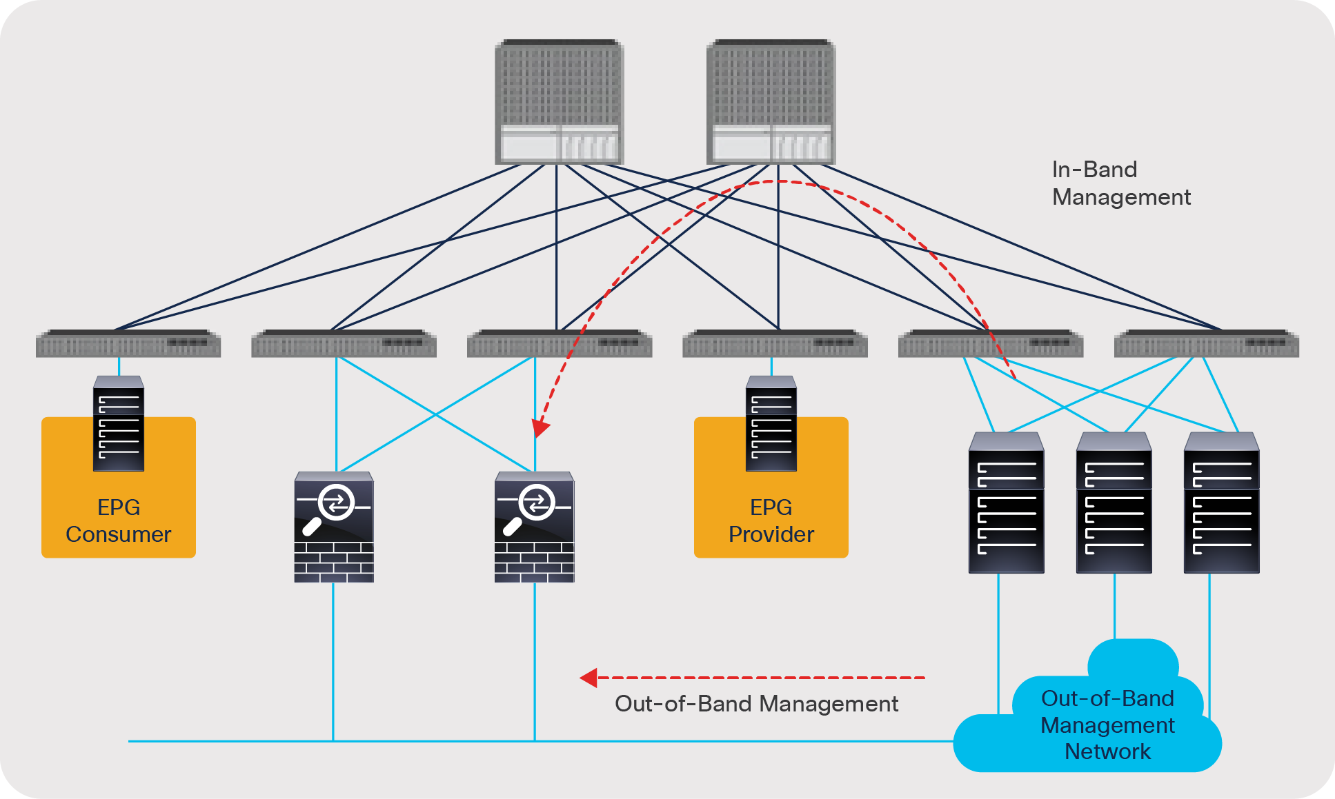
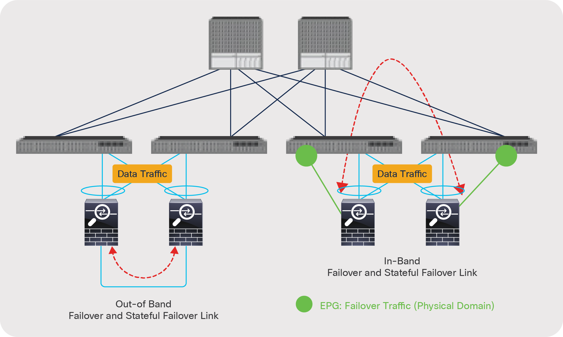
When deploying an L4-L7 device with ACI, you can choose to manage the service node (that is, the L4-L7 device) either with out-of-band management or in-band management (Figure 43):
● Out-of-band management: With this approach you simply use a management network outside the Cisco ACI fabric. With out-of-band management, Cisco APIC doesn’t have to manage/configure the management network.
● In-band management: With this approach you can use any ACI tenant where you would configure a VRF, BD, and EPG for the management traffic or the special tenant mgmt, the VRF inb, and the user-created BD and EPG. This second approach is required if there is a need to provide reachability between the APIC and the L4-L7 appliance or the L4-L7 management device through the in-band network.
Management network
To set up end-to-end connectivity between EPGs through the service node, you need to create data path networks for service nodes. This process is performed during service graph rendering based on the configuration in the device selection policy. This section describes domain and VLAN pool configuration for data traffic on both physical and virtual service devices.
L4-L7 device in physical domain
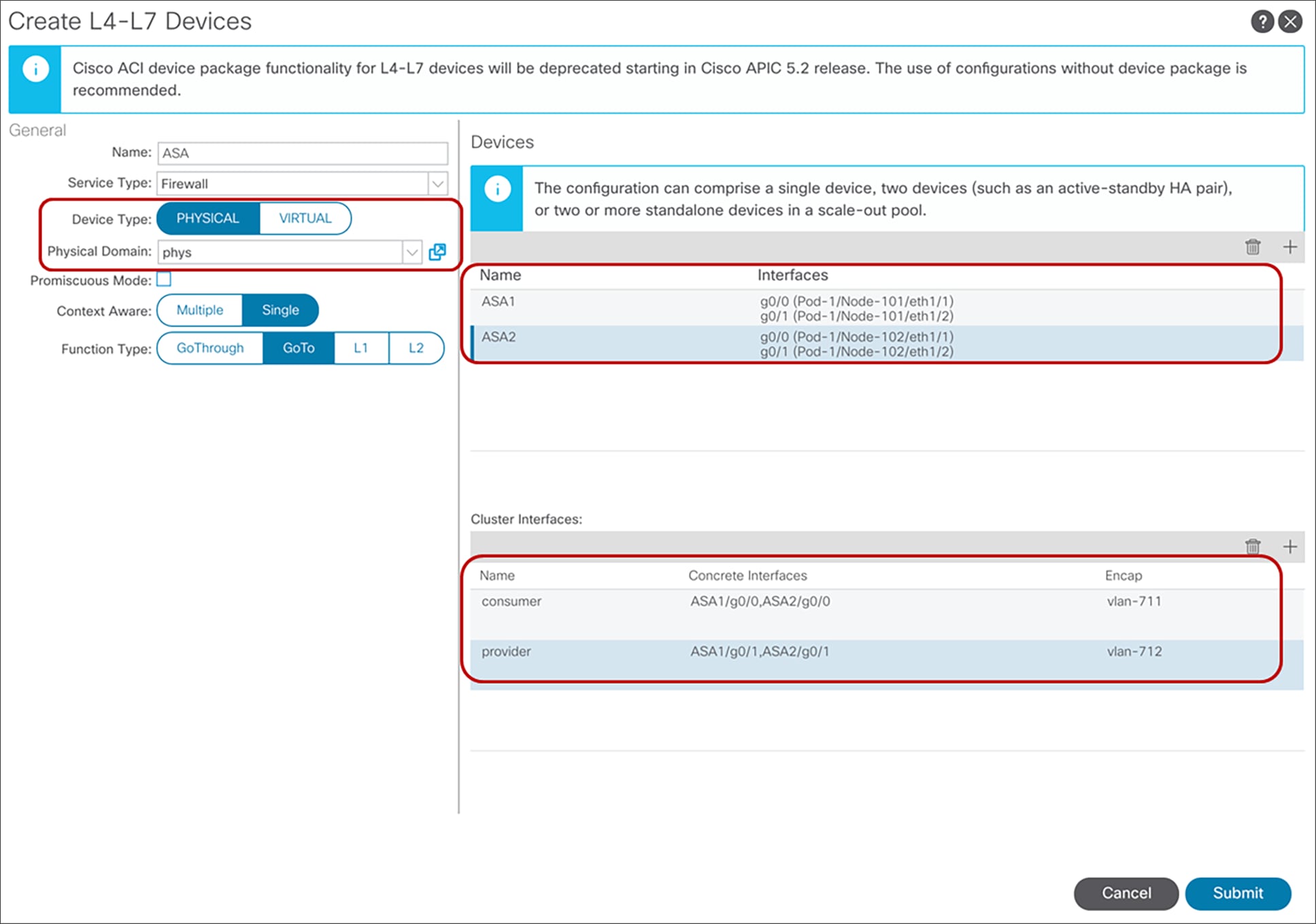
For L4-L7 devices in a physical domain, specify the physical domain with the static allocation mode for the VLAN range for the L4-L7 device.
Specify the path and VLAN ID in the cluster interface, which are similar to the specifications for static path bindings for the EPG (Figure 44). Based on this VLAN and path configuration, VLANs are programed on the leaf interfaces through service graph deployment. Thus, you need to configure all of possible leaf interfaces connected to the service devices. If you have an active/standby service device pair, you need to add both service devices as concrete devices. In this example, ASA1 and ASA2 are an active/standby firewall pair.
L4-L7 device in physical domain configuration
In the case of L1 or L2 mode with Active-Active, specify the VLAN ID in the concrete interface instead of in the cluster interface (Figure 45).
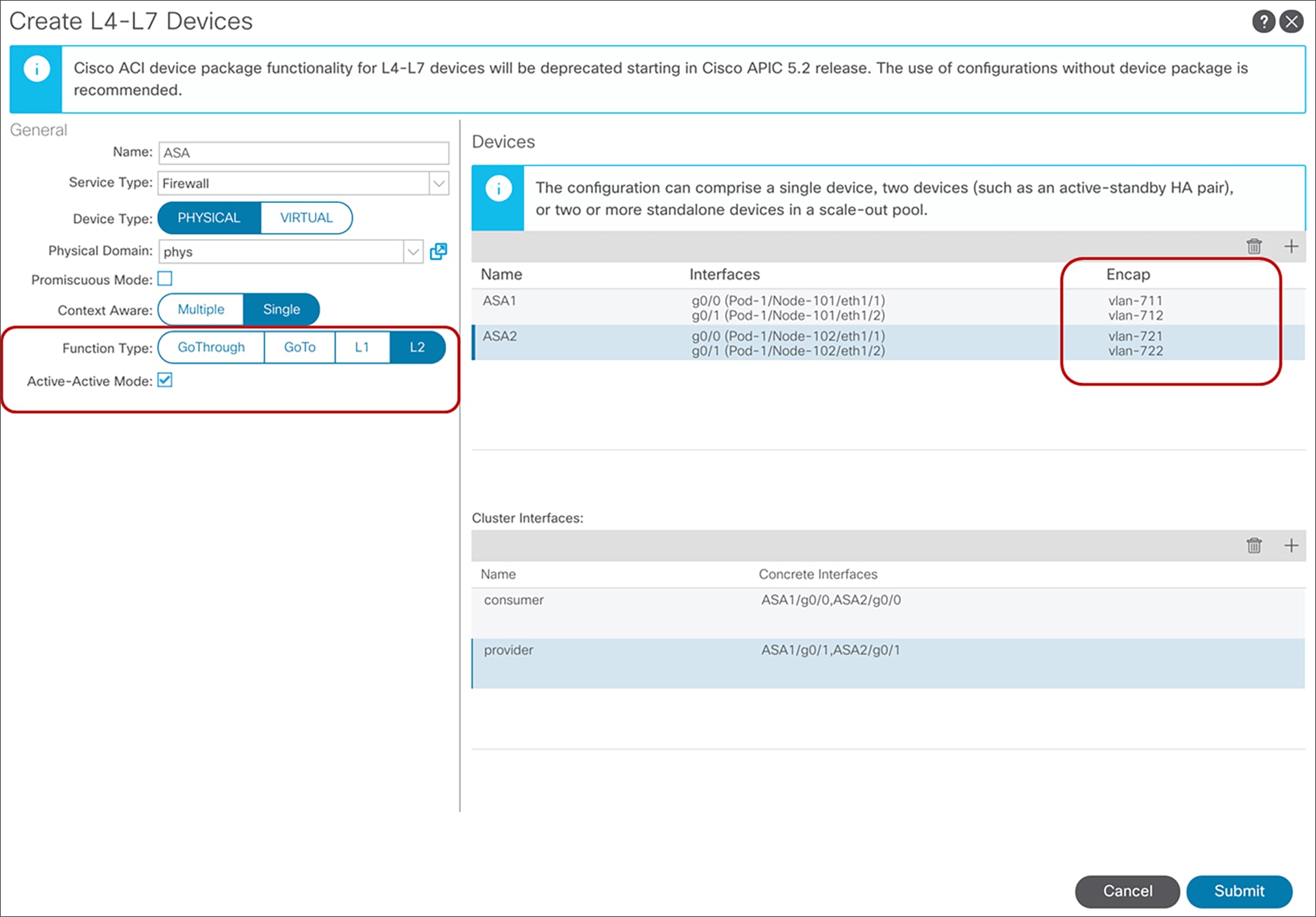
L4-L7 device in physical domain configuration for L1/L2 mode with Active-Active mode
Note: In the case of L1 mode with Active-Active, the consumer and provider connectors must be connected under different leaf nodes.
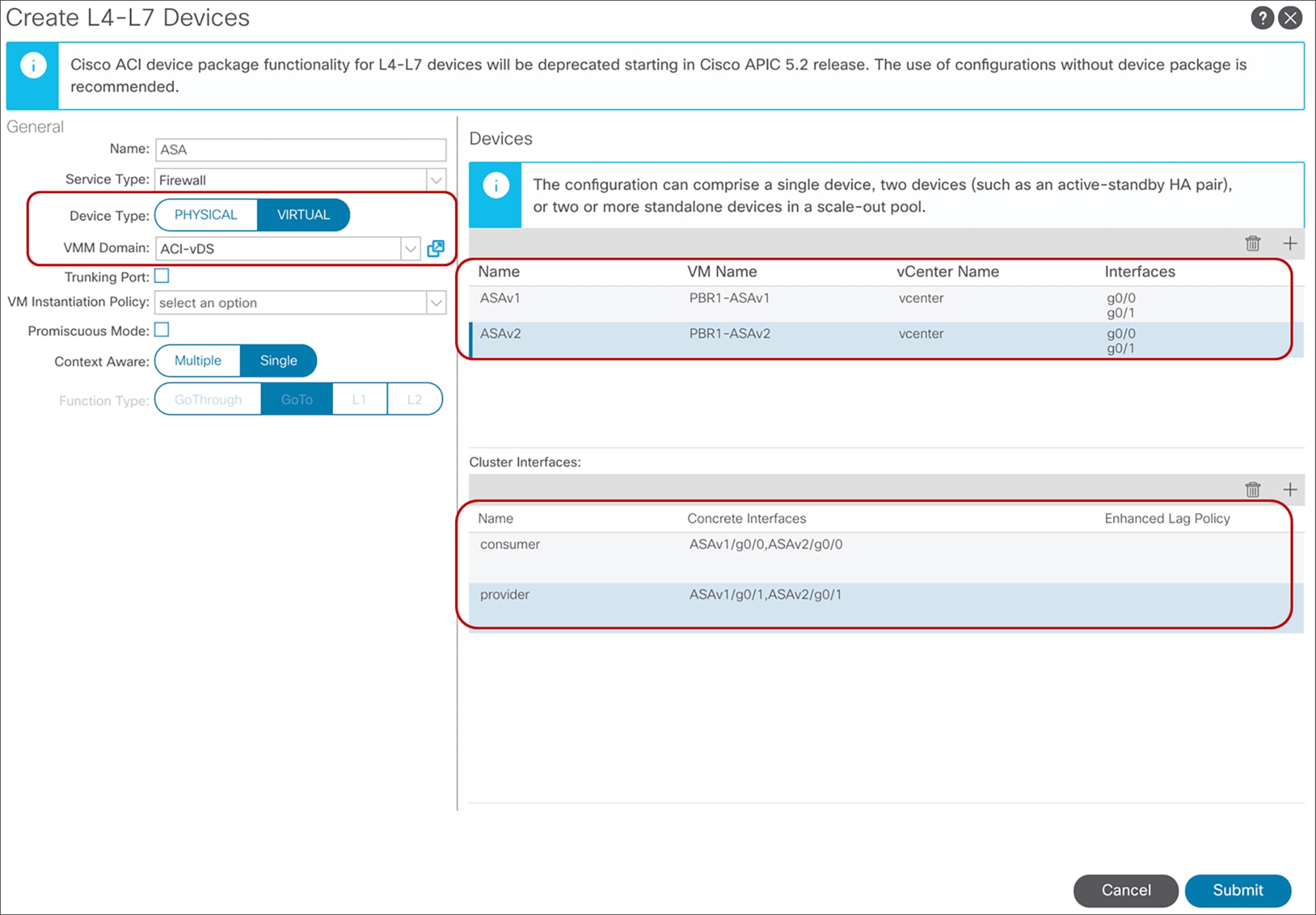
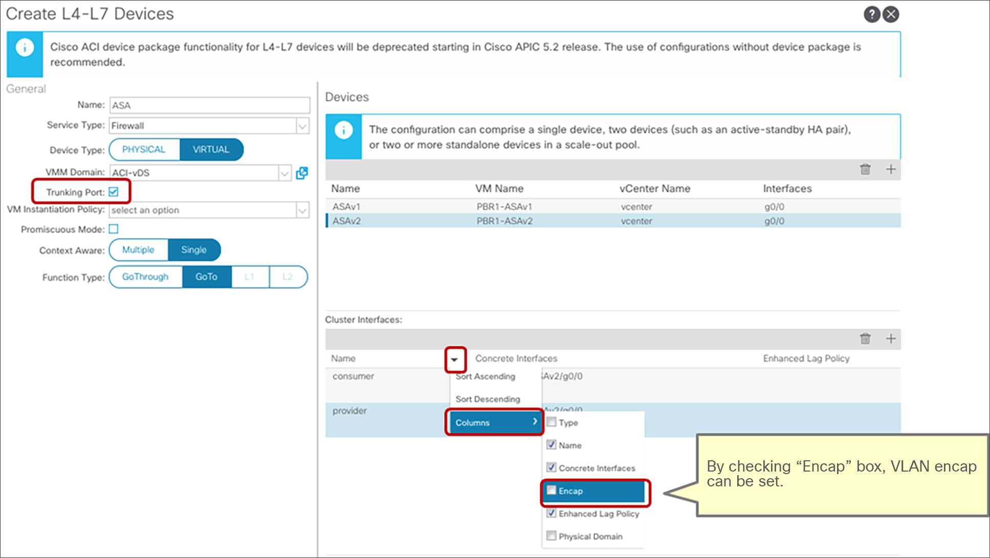
For virtual appliances, specify the virtual machine manager (VMM) domain using the dynamic allocation mode for the VLAN range for the L4-L7 device (Figure 46). The APIC will select VLANs from the VLAN range, configure the Cisco ACI fabric, create port groups for the service node connector, and change the vNIC configuration of the virtual appliance during service graph rendering.
The VMM domain can also contain a VLAN range that uses static allocation mode, but the VLAN range specified with dynamic allocation mode will be used for service graph deployment.
Specify the VM name and the vNICs of the VM: this is required for automatic vNIC placement. Path configuration is not mandatory unless the L3Out is used for the service device connectivity. For L3Out, the APIC selects the VLAN that is used in the L3Out logical interface profile configuration. If you have an active/standby service device pair, you need to add both service device VMs as concrete devices. In this example, ASAv1 and ASAv2 are an active/standby firewall pair.
Virtual appliance configuration
Note: As of this writing, automatic vNIC placement is supported for the virtual appliance running in the VMware VMM domain and SCVMM VMM domain only. There is no integration at this point between the service graph and other VMM domain types such as Red Hat, OpenStack, and VMware SDN domains.
Depending on the design, the following port-group-related configuration options need to be enabled:
● Promiscuous mode: A port-group with promiscuous mode is required if the L4-L7 virtual appliance needs to receive traffic destined to a MAC that is not the vNIC MAC owned by the VM. By default, promiscuous mode is disabled on the port group created through service graph deployment using a Go-To mode L4-L7 device. By checking this option in the Create L4-L7 Device configuration, promiscuous mode is enabled on the port group.
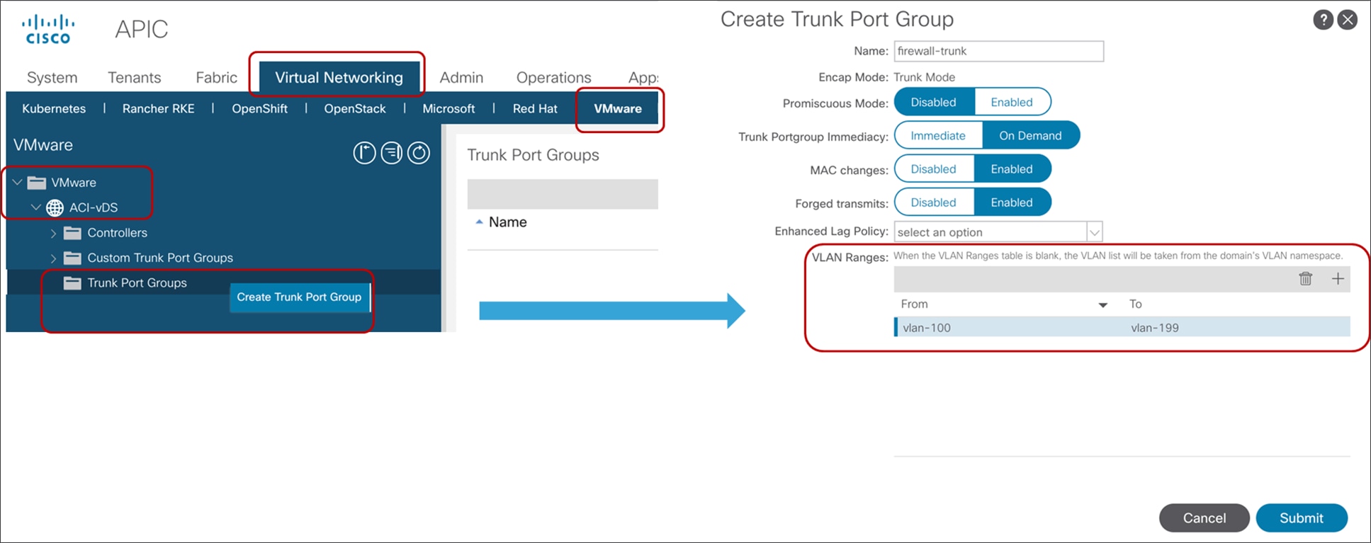
● Trunk port groups: By default, the ACI service graph configuration creates access-mode port groups and attaches them to the vNIC of the L4-L7 VM automatically to it. Thus, the L4-L7 VM receives untagged traffic. If, instead, you want the L4-L7 VM to send and receive tagged traffic you can use a trunk port group. By checking this option in the Create L4-L7 Device configuration, the automatic vNIC placement doesn’t occur. This option is available starting from Cisco ACI Release 2.1. As the service graph with this option doesn’t take care of trunk-port-group creation or automatic vNIC placement for the VM, you need to create a trunk port group that allows necessary VLANs and attach the trunk port group to the vNIC of the VM in addition to the service graph configuration. A trunk port group can be created at Virtual Networking > VMware > Domain name > Trunk Port Groups (Figure 47). When using trunk port groups, the service graph deployment doesn’t automatically generate a VLAN for the cluster interface, nor does it place the vNIC automatically, hence the administrator must associate the L4-L7 device cluster interface to the correct VLAN that is configured on the L4-L7 device similarly to the deployment with physical domains. To configure L4-L7 VM interfaces by using correct VLAN IDs, it is necessary to use static VLAN allocation instead of dynamic VLAN allocation. By default, VLAN IDs for L4-L7 device interfaces are dynamically allocated in the case of an L4-L7 device in a VMM domain, but you can add a static VLAN range to a dynamic VLAN pool. The VLAN encap can be assigned statically to the cluster interface by checking the “encap” box at the cluster interface configuration (Figure 47).
● Enhanced LAG policy: If the VMware vDS used for the VMM domain has VMware link aggregation groups (LAGs), you need to specify an LAG policy for each cluster interface; that is, the LAG policy for the port group created through service graph deployment. This option is available starting from Cisco ACI Release 5.2.
Virtual appliance configuration with trunk port group
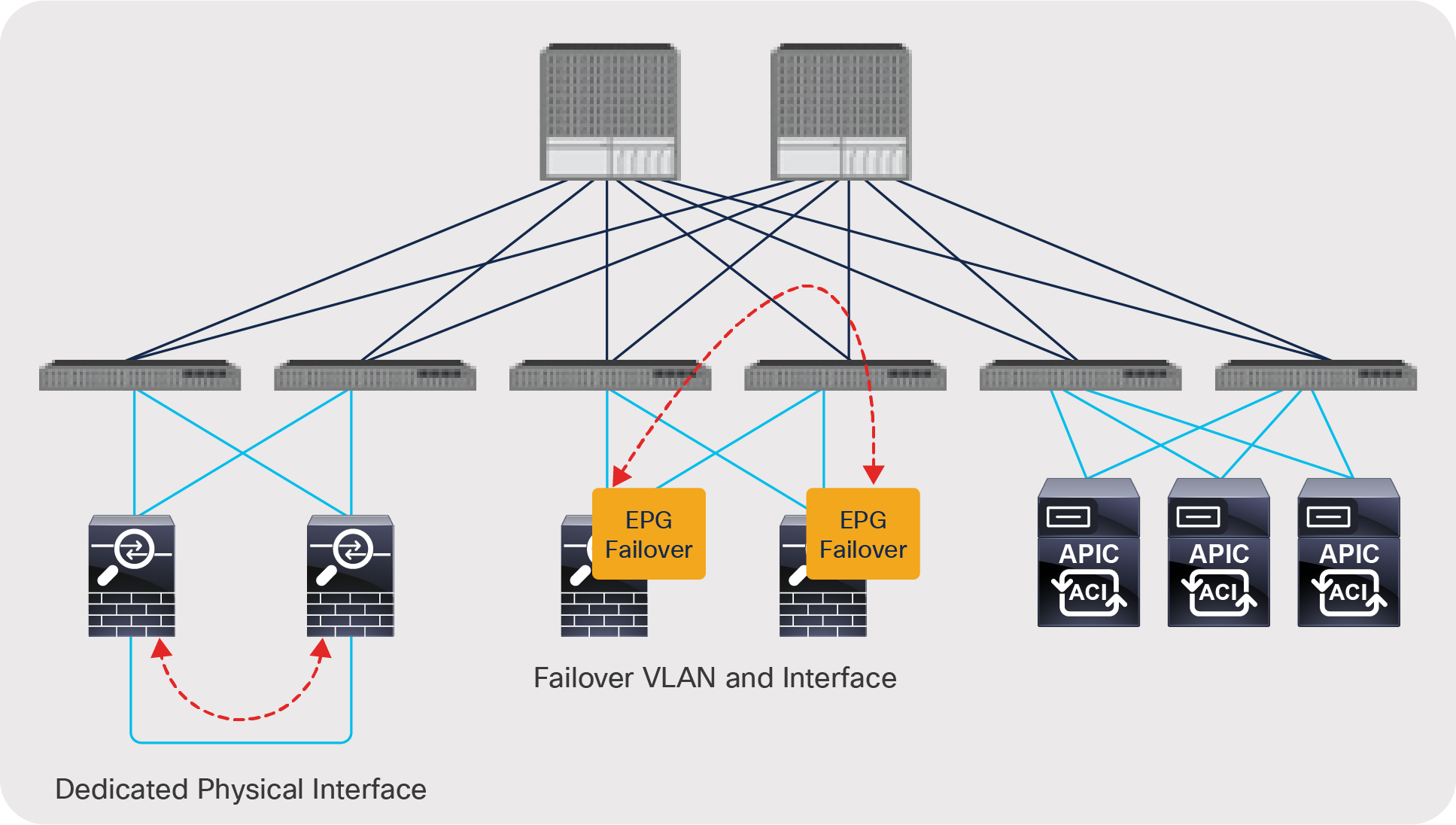
Each service device vendor has different failover link options and mechanisms (Figure 48). Typical options are listed here:
● Dedicated physical interface for failover traffic (for example, F5 devices): The service device has a dedicated physical interface for failover traffic only.
● Created failover VLAN and interface (for example, Cisco Adaptive Security Appliance [ASA] devices): The service device doesn’t have a dedicated physical interface. You need to create a failover VLAN or choose interfaces for failover traffic, which typically are created on different physical interfaces, with one for data traffic.
● Shared (not dedicated) VLAN and logical interface (for example, Citrix devices): Failover traffic is exchanged over the same VLAN as data traffic.
Typically, use of a dedicated physical interface and a directly cabled pair of failover devices is recommended. If failover interfaces are connected to each service device directly, Cisco ACI fabric doesn’t have to manage the failover network. If you prefer to use in-band failover traffic within Cisco ACI fabric, you need to create an EPG for failover traffic.
Failover network design option
High-availability design considerations
This section describes high-availability design and considerations for both physical and virtual appliances: in particular, Cisco Adaptive Security Appliance / Firepower Threat Defense (ASA/FTD) appliances. ASA/FTD appliances don’t have dedicated physical interfaces for failover traffic, so you need to create failover interfaces: a failover link and a stateful failover link. These interfaces are for failover communication only and are commonly used as individual interfaces.
For detailed information about ASA/FTD failover, please see the documents at: https://www.cisco.com/c/en/us/td/docs/security/asa/asa914/configuration/general/asa-914-general-config/ha-failover.html.
and
If the failover traffic is within the Cisco ACI fabric (in band), you need to configure an EPG for failover traffic. If the service device is a virtual appliance, you also need to configure vNICs for the virtual appliance, because the APIC doesn’t do this automatically.
High-availability connectivity from the physical appliance to the fabric
Cisco ASA/FTD doesn’t allow user data traffic and failover traffic to share interfaces, even with different sub-interfaces. You must use a separate dedicated interface for the failover link. On the Cisco ACI fabric, you need to create an EPG with static bindings for failover traffic. You can use different EPGs for the failover link and the stateful failover link (Figure 49).
Physical appliance connectivity
High-availability connectivity from the virtual appliance to the fabric
You need to create an EPG for the VMM domain for failover traffic (Figure 50), which creates port groups for the EPG. Then you need to configure vNICs for the virtual appliance. You can use an EPG with static bindings if you don’t want to use the VMware VMM domain. In this case, you manually create a port group for failover traffic and configure static bindings for the EPG.
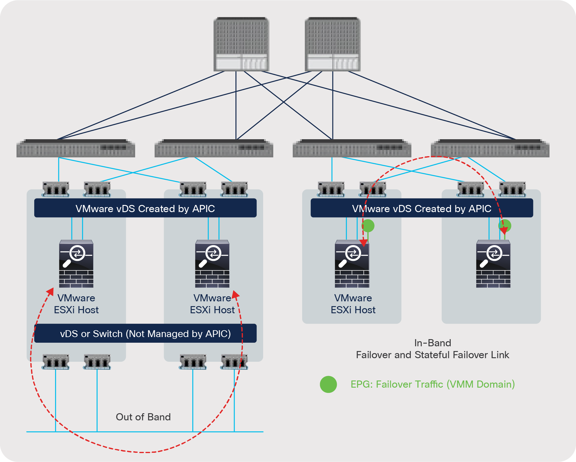
Virtual appliance connectivity
Deploying redundant physical appliances
If you have an L4-L7 service device HA pair, such as a physical ASA or FTD pair, configured in single tenant mode, you need to add both service devices as concrete devices in the L4-L7 device configuration, as explained in the section “L4-L7 device in physical domain”. In the cluster interface configuration for a two-arm deployment, you would define one consumer-side (outside or client-side) interface that is associated with the consumer-side interface of both physical ASA/FTDs, and a provider-side (inside or server-side) interface that is associated with the provider-side interface of both physical ASA/FTDs.
Both ASA and FTD devices also offer multi-tenancy, and there are differences in how the failover configuration is applied. When an ASA device is deployed in a multi-context mode, an administrator applies the failover configuration once in the system context, adding redundancy for all configured user contexts and their assigned VLAN sub-interfaces.
ASA active/standby user contexts that are deployed for service graph firewall insertion must be added as individual L4-L7 devices on the APIC (Figure 44 and 45).
Physical FTD devices deployed in multiple instance mode (a.k.a. containers) require the failover configuration to be applied to each instance pair.
Just as in the case of ASA, these FTD active/standby instances are added as individual L4-L7 devices in APIC to apply firewall inspection as part of the service graph.
In the service graph L4-L7 device configuration, you don’t have to configure a cluster interface for the failover link and stateful failover link in the L4-L7 device because they are not part of a service graph. If failover traffic is not within the Cisco ACI fabric (that is, if it is out of band), the Cisco ACI fabric doesn’t need a BD or an EPG for this. If the failover traffic is within the Cisco ACI fabric (in band), the L4-L7 device configuration on the APIC doesn’t manage the EPG creation for failover traffic either. You just need to create a BD and an EPG for failover traffic as described in the section “High-availability connectivity from the physical appliance to the fabric.”
Deploying redundant virtual appliances
If you have L4-L7 service virtual appliances to be deployed as an HA pair, you need to add both service device VMs as concrete devices in the L4-L7 device configuration, as explained in the section “L4–L7 device in virtual domain.” In the cluster interface configuration for a two-arm deployment, you would define one consumer-side interface that is associated with the consumer-side (outside or client-side) interface of both virtual appliances, and a provider-side (inside or server-side) interface that is associated with the provider-side interface of both virtual appliances.
As already explained in the section “High availability connectivity from the virtual appliance to the fabric,” regardless of whether you are using in-band or out-of-band to transport failover traffic, you need to create a port group for failover traffic on the virtualized host and attach the correct vNIC used by the L4-L7 device for failover to this port group.
If failover traffic is not within the Cisco ACI fabric (if it is out of band), the Cisco ACI fabric doesn’t need a BD or an EPG for this. If the failover traffic is within the Cisco ACI fabric (in band), you need to create a BD and an EPG to carry this traffic.
When you create an L4-L7 device on the APIC, don’t add the vNIC used for failover to the L4–L7 device configuration: failover interfaces are not added as concrete interfaces (Figure 46).
Deploying active/active clustering for physical appliances (Cisco ASA/FTD cluster)
Cisco ASA/FTD clustering allows you to group multiple ASA or FTD nodes together as a single logical device to provide high availability and scalability. ASA/FTD clustering also can be integrated with Cisco ACI. Cisco firewall clustering has two modes: spanned EtherChannel mode (recommended and supported on both ASA and FTD) and individual interface mode (ASA-only mode). This document focuses on the recommended spanned EtherChannel mode.
One member of the cluster is elected as the primary and secondary node, which handles the configuration and replicates it to all subordinate nodes. The primary node handles traffic just like any other node in the cluster. In the spanned EtherChannel mode, all ASA or FTD devices in the same cluster use the same port channel, and traffic is load balanced as part of the port-channel operation. From the perspective of the Cisco ACI fabric, the cluster is a single logical device with a single concrete device connected to the Cisco ACI fabric through one port channel (Figure 51).
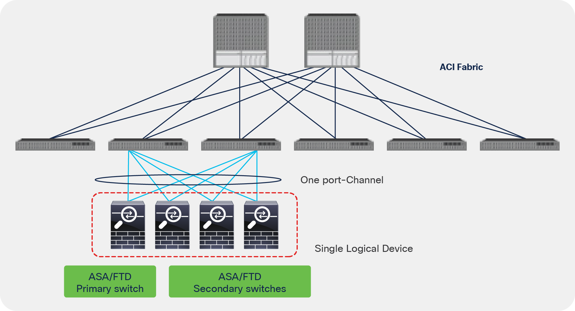
Cisco ASA/FTD clustering
In the spanned EtherChannel mode, all ASA/FTD devices advertise the same IP and MAC address configured on the interfaces. Therefore, all nodes in the same cluster need to be connected to the Cisco ACI fabric through the same vPC or port channel. If cluster nodes were connected to multiple vPCs, firewall IP and MAC would be flapping between vPCs in the Cisco ACI fabric. This is because ACI would learn the same endpoint from different port-channel interfaces.
The ASA/FTD clustering solution has support for splitting units within the same cluster across multiple data centers. This is an elegant way to ensure the same security policy, retain the state of connections, and enable resiliency across all data centers. Prior to Cisco ACI Release 3.2(4), ASA/FTD clustering across ACI pods was not possible due to the endpoint flapping issues previously noted.
Starting from Cisco ACI Release 3.2(4), an ASA/FTD cluster can be stretched across pods even if there are two or more distinct vPCs (that is, one vPC in each pod). Using the anycast service feature added in this release, the PBR service graph enables coexistence of the clustered firewalls that have the same IP and MAC addresses in the local and remote pods.
ASA/FTD devices in the same cluster in the same pod still need to be connected to the same vPC or port channel.
The ACI fabric forwarding gives preference to traffic redirection to the cluster unit(s) in the local pod while providing high availability with the use of remote units in case of a local pod unit failure.
Figure 52 illustrates the configuration of an ASA/FTD cluster within one pod. The definition of the L4 – L7 device includes only one concrete device. The concrete device can have one or more concrete interfaces and cluster interfaces depending on how the cluster is physically and logically connected.
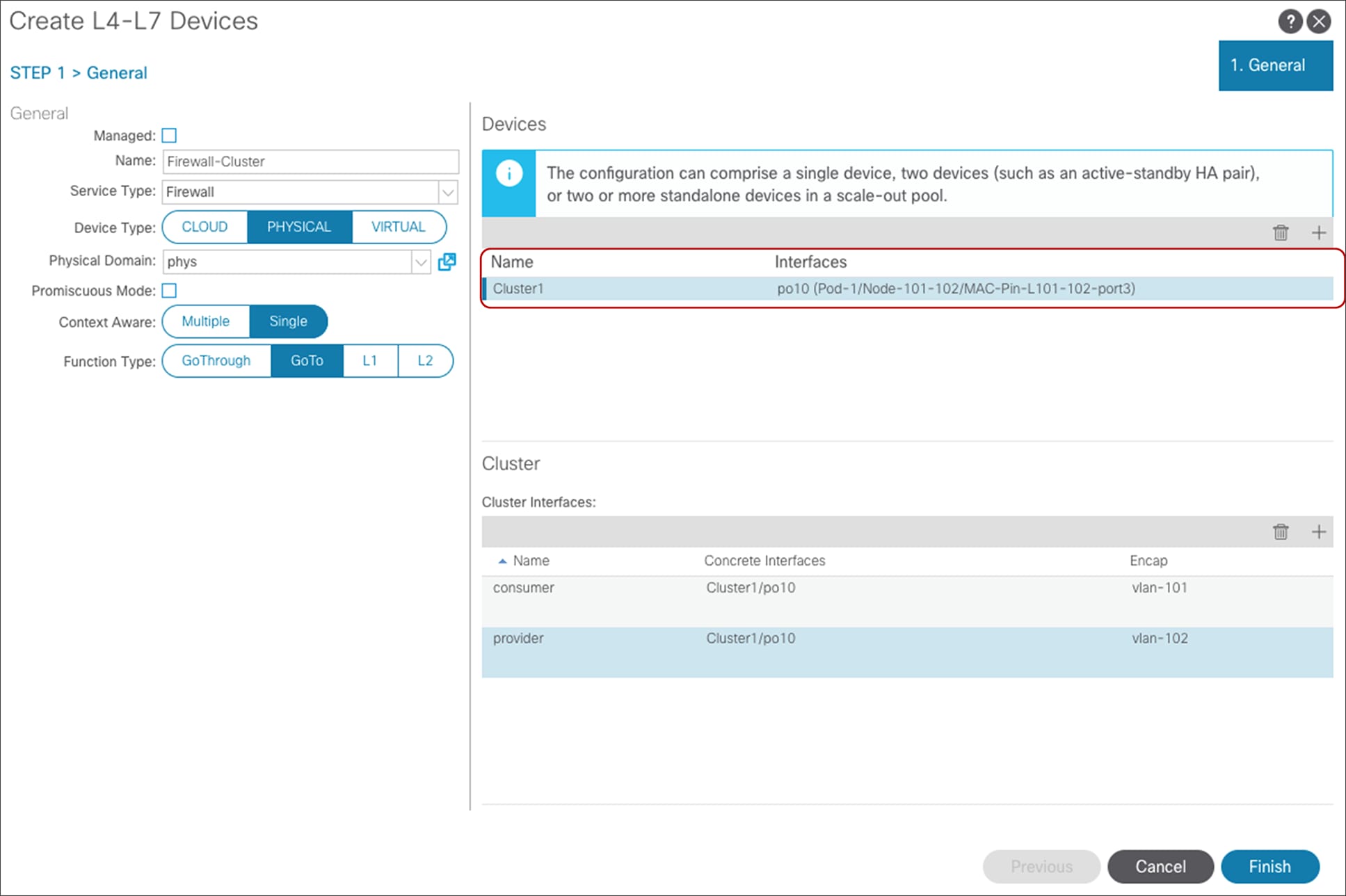
L4-L7 device configuration for ASA/FTD clustering (one concrete device for single pod)
Note: Although this section explains how to define an L4-L7 device for a cluster, the use of service graph is not mandatory to connect a cluster to an ACI fabric.
In the case of Multi-Pod with anycast service, devices in the same pod connected to the ACI fabric through the same port channel are one big logical device. Thus, one L4-L7 device contains multiple concrete devices. For example, in Figure 53, concrete device1 consists of the firewalls in pod1 and concrete device2 consists of the firewalls in pod2.
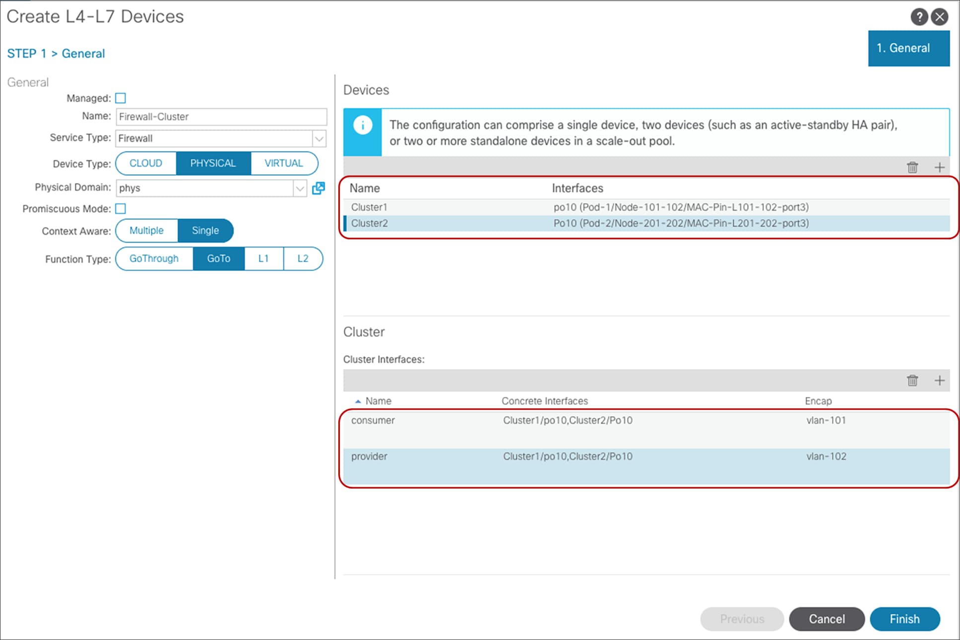
L4-L7 device configuration for ASA/FTD clustering (multiple concrete devices for Multi-Pod)
To set up ASA/FTD clustering, you need separate interfaces or port channels for the cluster control plane in addition to the spanned EtherChannel for cluster data plane (Figure 54). You may need to create an EPG and the port channel interface for the cluster control plane traffic, and these are not part of the service graph configuration:
● If the control plane traffic is not within the Cisco ACI fabric (if it is out of band), Cisco ACI fabric doesn’t have to provide connectivity for the control plane traffic.
● If the control plane traffic is within the Cisco ACI fabric (in band), the L4-L7 device configuration on the APIC doesn’t create the EPG for control plane traffic.
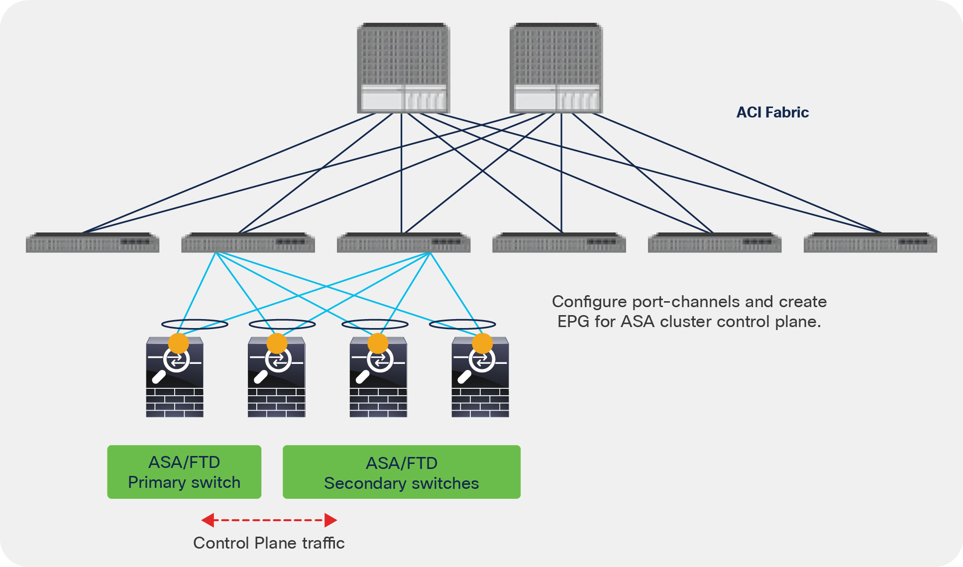
Port channels for cluster control plane
For more information about ASA/FTD clustering, see the configuration guides at https://www.cisco.com/c/en/us/td/docs/security/firepower/670/configuration/guide/fpmc-config-guide-v67/clustering_for_the_firepower_threat_defense.html or https://www.cisco.com/c/en/us/td/docs/security/asa/asa97/configuration/general/asa-97-general-config/ha-cluster.html.
For more information about ASA/FTD clustering across pods, see Cisco ACI Multi-Pod and Service Node Integration White Paper at https://www.cisco.com/c/en/us/solutions/collateral/data-center-virtualization/application-centric-infrastructure/white-paper-c11-739571.html.
Design for sharing L4-L7 appliances
Some L4-L7 appliances have multitenant functions. These functions differ by vendor. This section describes multitenant design using Cisco ASA and F5 BIG-IP. It also describes how to share an L4-L7 device among different tenants and use multiple service graph rendering.
Multiple tenants: Using a Cisco ASA/FTD physical appliance
The ASA context and FTD instance capabilities provide multiple service appliances on the same physical hardware. Each service appliance has a different configuration space, a different management IP address, different credentials, etc. The Cisco ACI service graph treats each virtual context as a concrete device (L4-L7 device on the APIC), so you can share one ASA physical device across multiple tenants and use multiple service graph rendering (Figures 55 and 56).
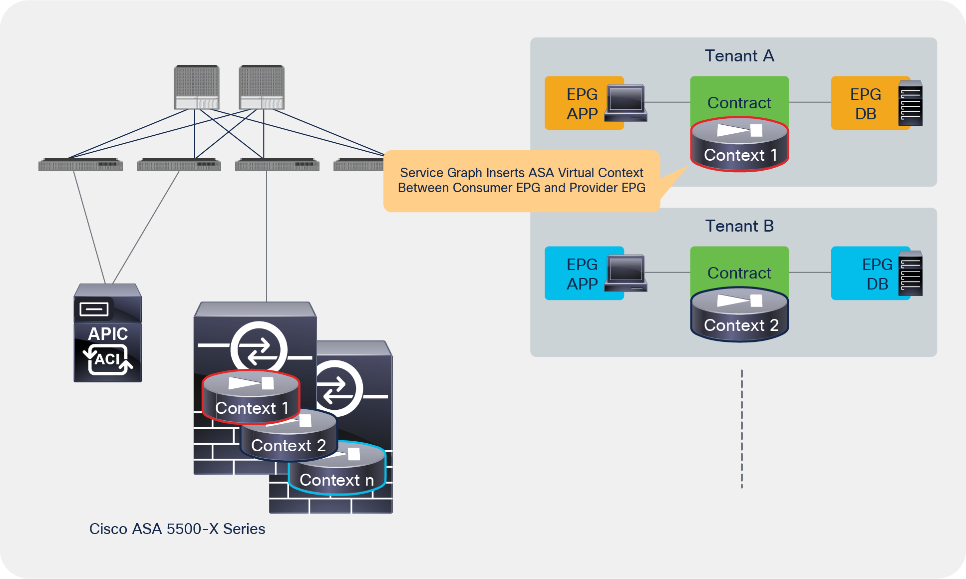
Cisco ASA/FTD virtual context
Starting from Cisco FTD Release 6.6.0, both physical and virtual FTD appliances support VRF. The VRF in FTD provides routing table isolation, but because all VRFs are in the same virtual context or in the same virtual device and share the same management IP address, this is different from the virtual context capability.
F5 BIG-IP Local Traffic Manager (LTM) has a route domain capability similar to that of a VRF. It provides routing table isolation, but all partitions are in the same service device and share the same management IP address.
Note: Some BIG-IP LTM platforms support virtual clustered multiprocessing (vCMP), which is similar to the ASA virtual context. vCMP allows you to run multiple instances of the BIG-IP software on a single hardware platform. For details, please see the F5 documentation.
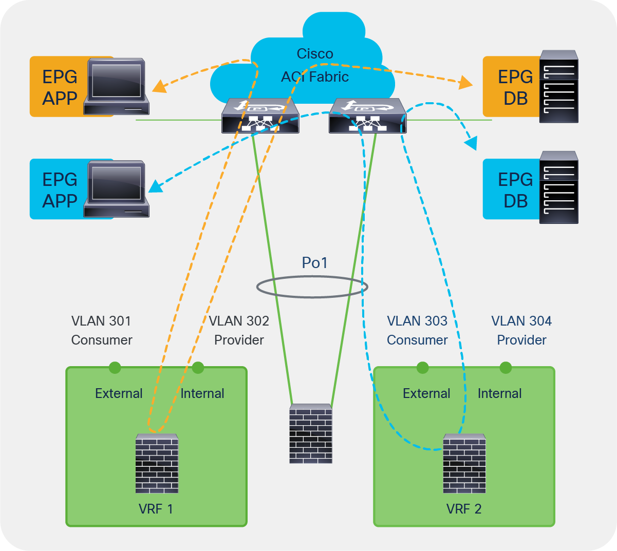
F5 BIG-IP multitenant design
Sharing L4-L7 devices with another tenant
L4-L7 device can’t be referenced from other tenants. If you want to share an L4-L7 device with other tenants, you need to export the L4-L7 device to other tenants. It will appear as an imported device in the other tenants (Figure 57). The requirement to export the L4-L7 device applies equally when the L4-L7 device is defined in common tenant.
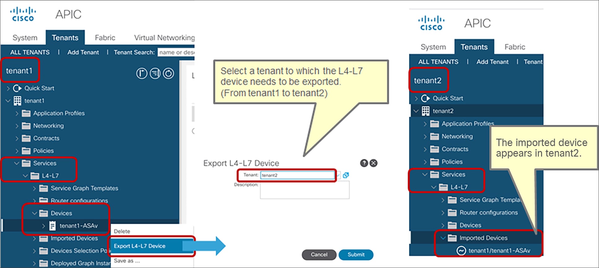
L4-L7 device configuration on Cisco APIC
Using an L4-L7 device with multiple service graphs
Each service graph has two connectors, for the consumer and the provider. However, in an actual deployment, the service appliance may have two or more interfaces to connect multiple servers in different zones, as shown in Figure 58. This section describes how to achieve this design with a service graph.
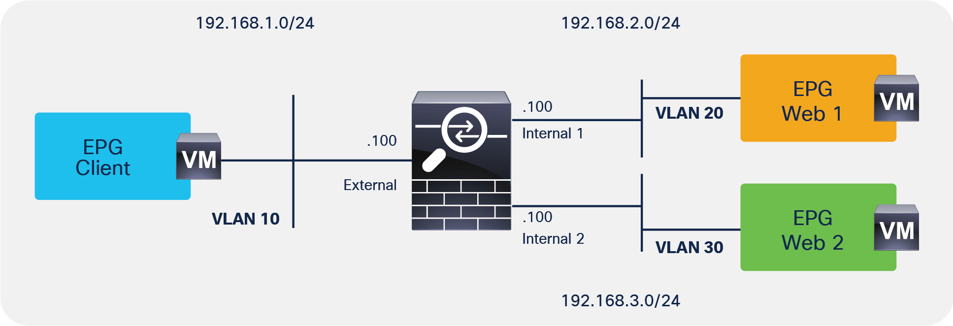
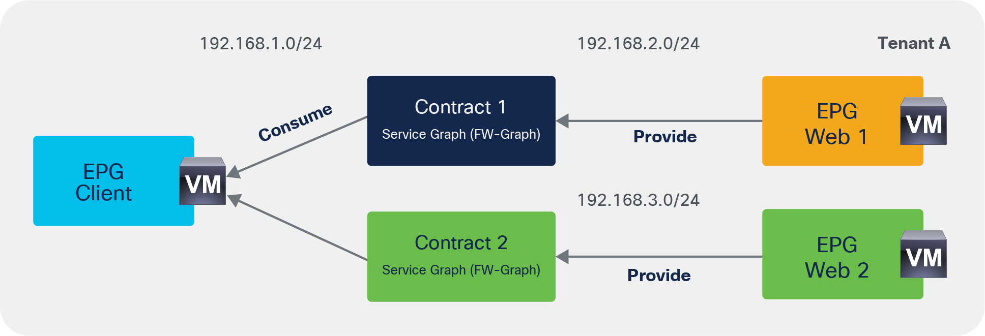
Using an L4-L7 device with multiple service graphs
Note: Because this example uses the firewall as the gateway, the firewall has an interface for each subnet. The use of different interfaces for each EPG subnet is not mandatory in the case of service graph with redirect, even if EPGs are in different subnets.
The main point is that you can create multiple cluster interfaces on a concrete device and then specify which cluster interface defined in the L4-L7 device will be used for the connector in the device selection policy. This cluster interface can be shared by multiple service graph instances.
This section explains three examples using an L4-L7 device in a physical domain or in a virtual domain using access mode port-groups or trunk mode port-groups. Please refer to the section “Data traffic” to understand how to define an L4-L7 device connected with VLAN trunking.
Example 1: Virtual L4-L7 appliance, shared consumer interface, access-mode port groups
The example in Figure 58 has three EPGs, two service graphs, and one concrete virtual service device. You create three cluster interfaces in the L4-L7 device (Figure 59). In this example the “Trunking Port” option is not checked, thus the service graph will create an access-mode port group for each cluster interface.
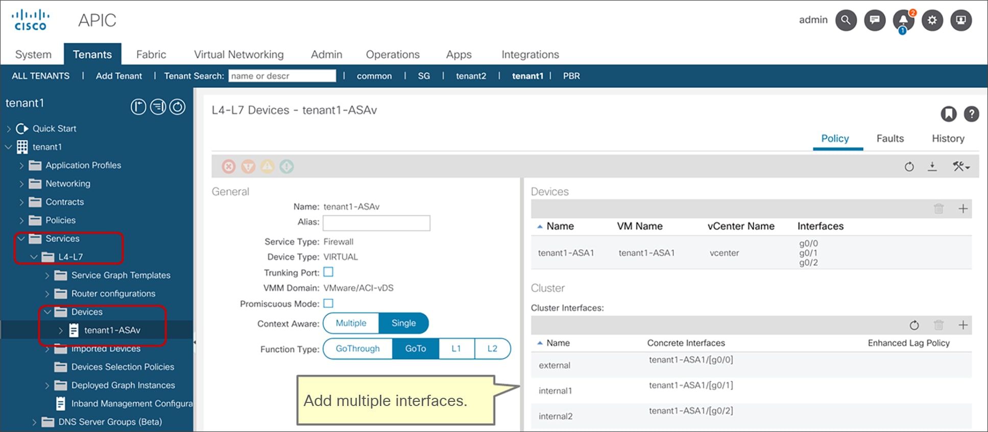
Cluster interface (virtual appliance)
In the device selection policy, you specify which cluster interface defined in the L4-L7 device will be used for the connector. This cluster interface can be shared by multiple service graph instances (Figures 60 and 61). In this example, the cluster interface “external” is used twice:
● Contract1 with Service-Graph uses cluster interface “external” as the consumer connector and “internal1” as the provider connector.
● Contract2 with Service-Graph uses cluster interface “external” as the consumer connector and “internal2” as the provider connector.
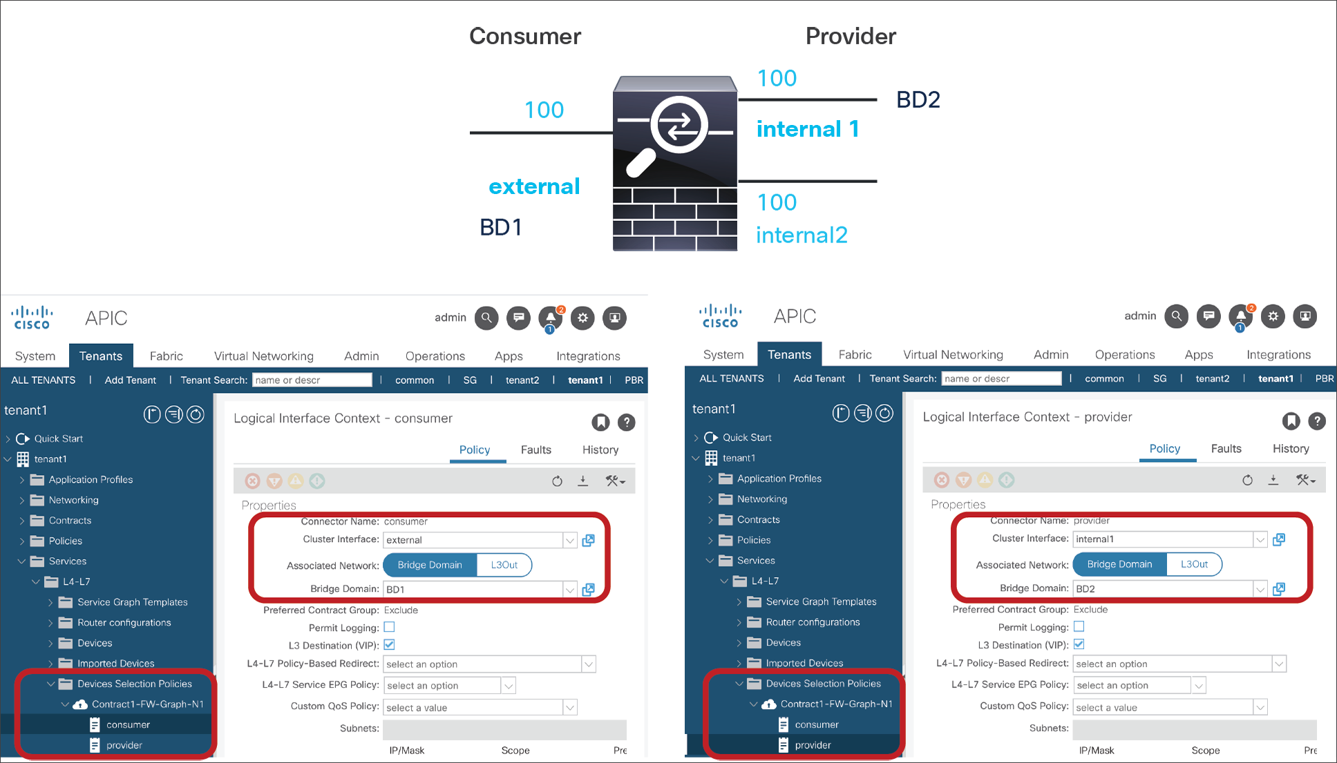
Device selection policy for Contract1 (virtual appliance)
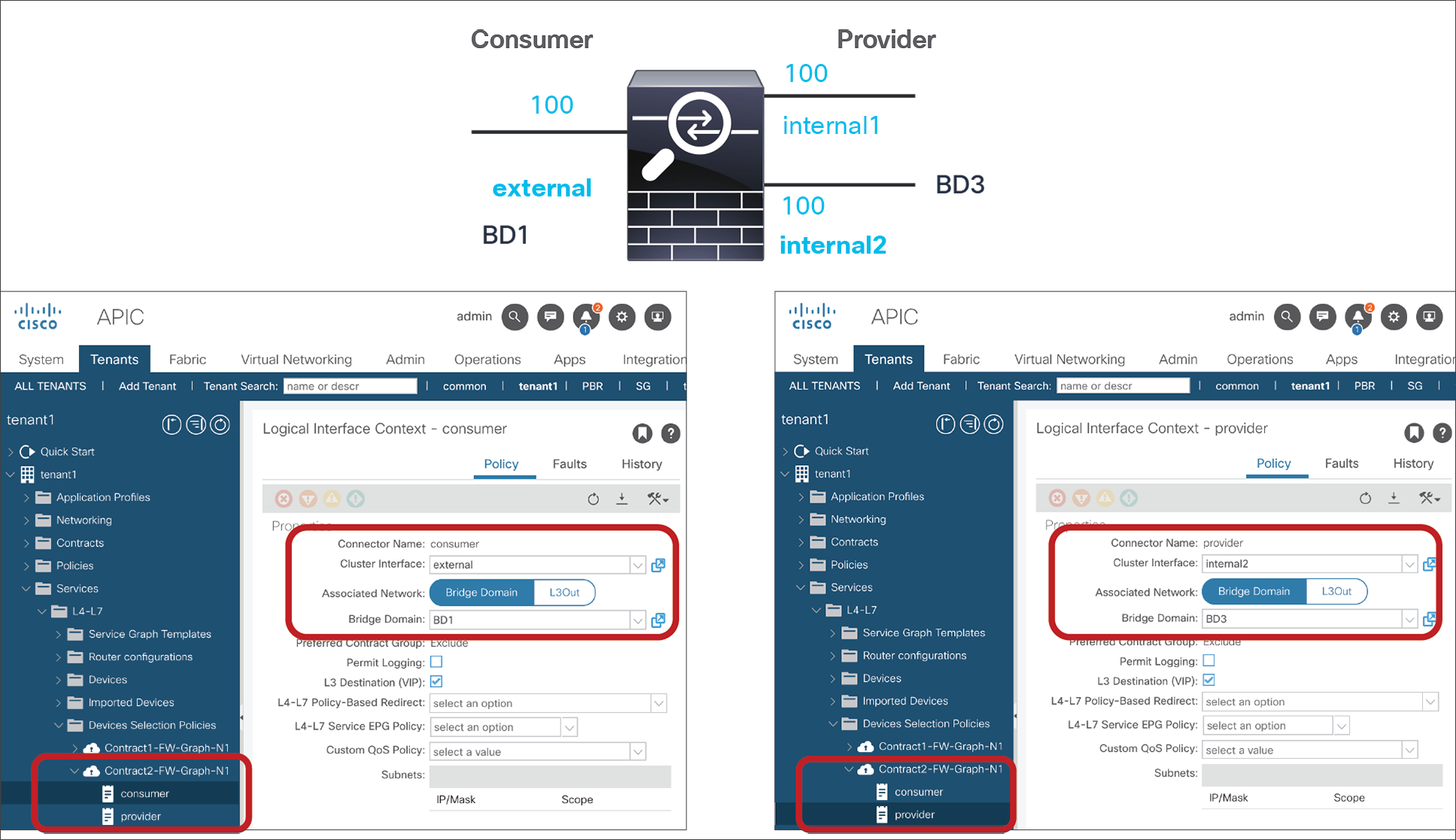
Device selection policy for Contract2 (virtual appliance)
Example 2: Virtual L4-L7 appliance, shared DMZ Interface, access-mode port groups
The example in Figure 62 has three EPGs, one service graph template, and one concrete virtual service device. You create three cluster interfaces in the L4-L7 device. In this example, the “Trunking Port” option is not checked, thus the service graph will create an access-mode port group for each cluster interface.
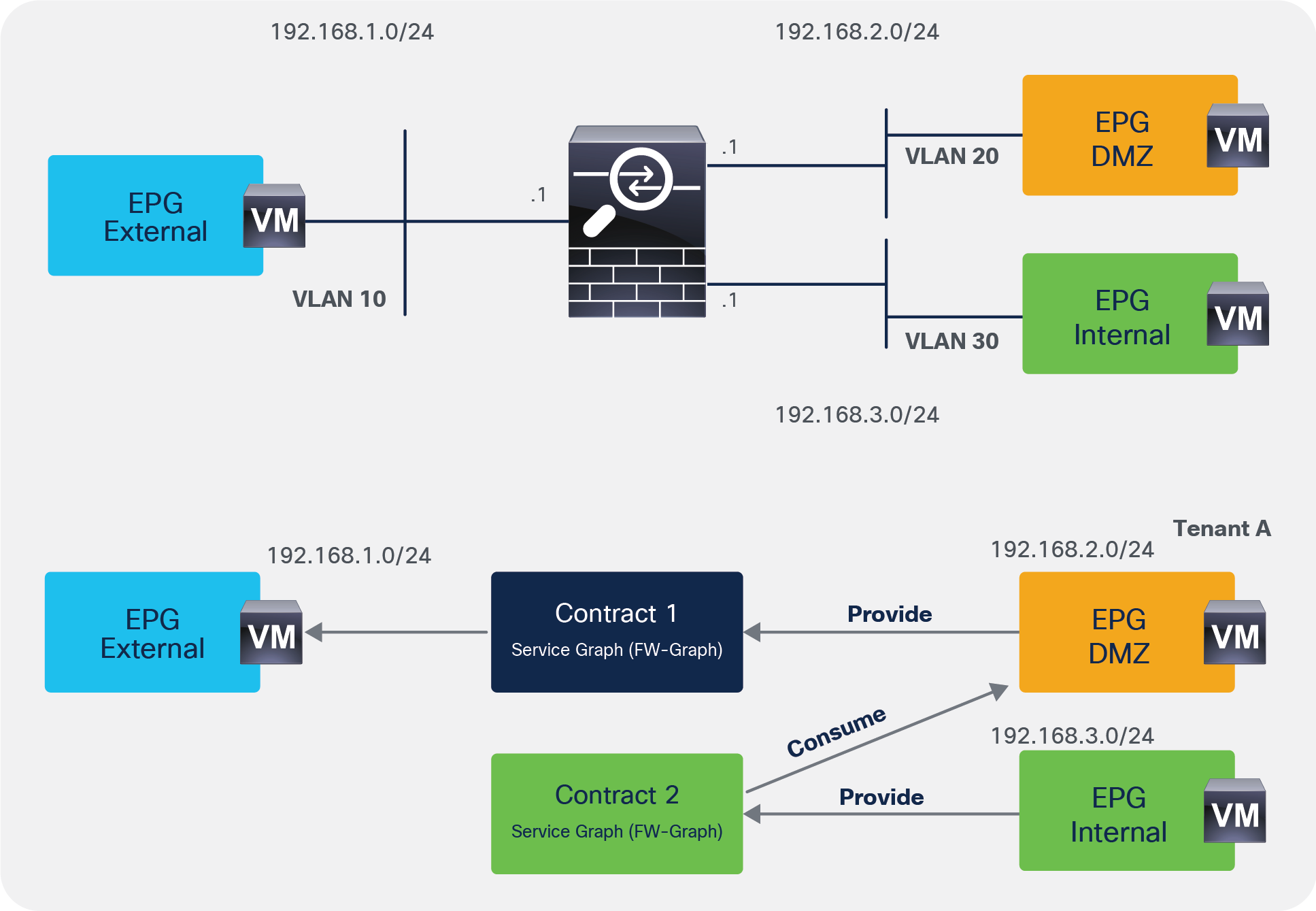
Cluster interface (virtual appliance)
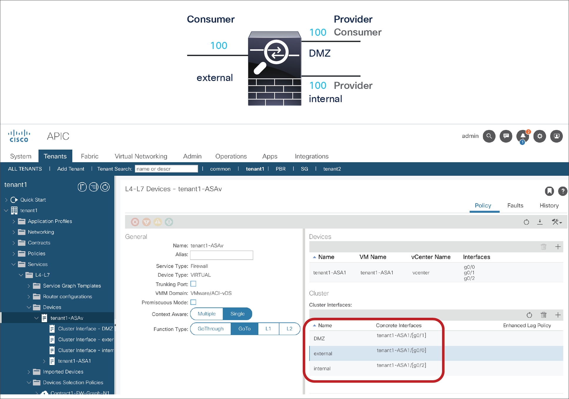
Configuring the options for the cluster interface
In this example, the cluster interface “DMZ” is used twice (Figures 64 and 65):
● Contract1 with Service-Graph uses cluster interface “external” as the consumer connector and “DMZ” as the provider connector.
● Contract2 with Service-Graph uses cluster interface “DMZ” as the consumer connector and “internal” as the provider connector.
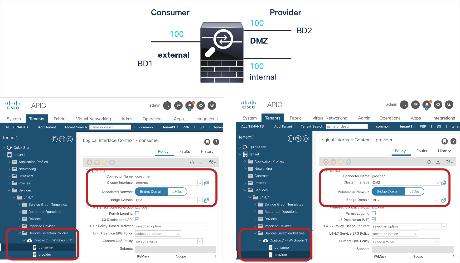
Device Selection Policy for Contract1 (virtual appliance)
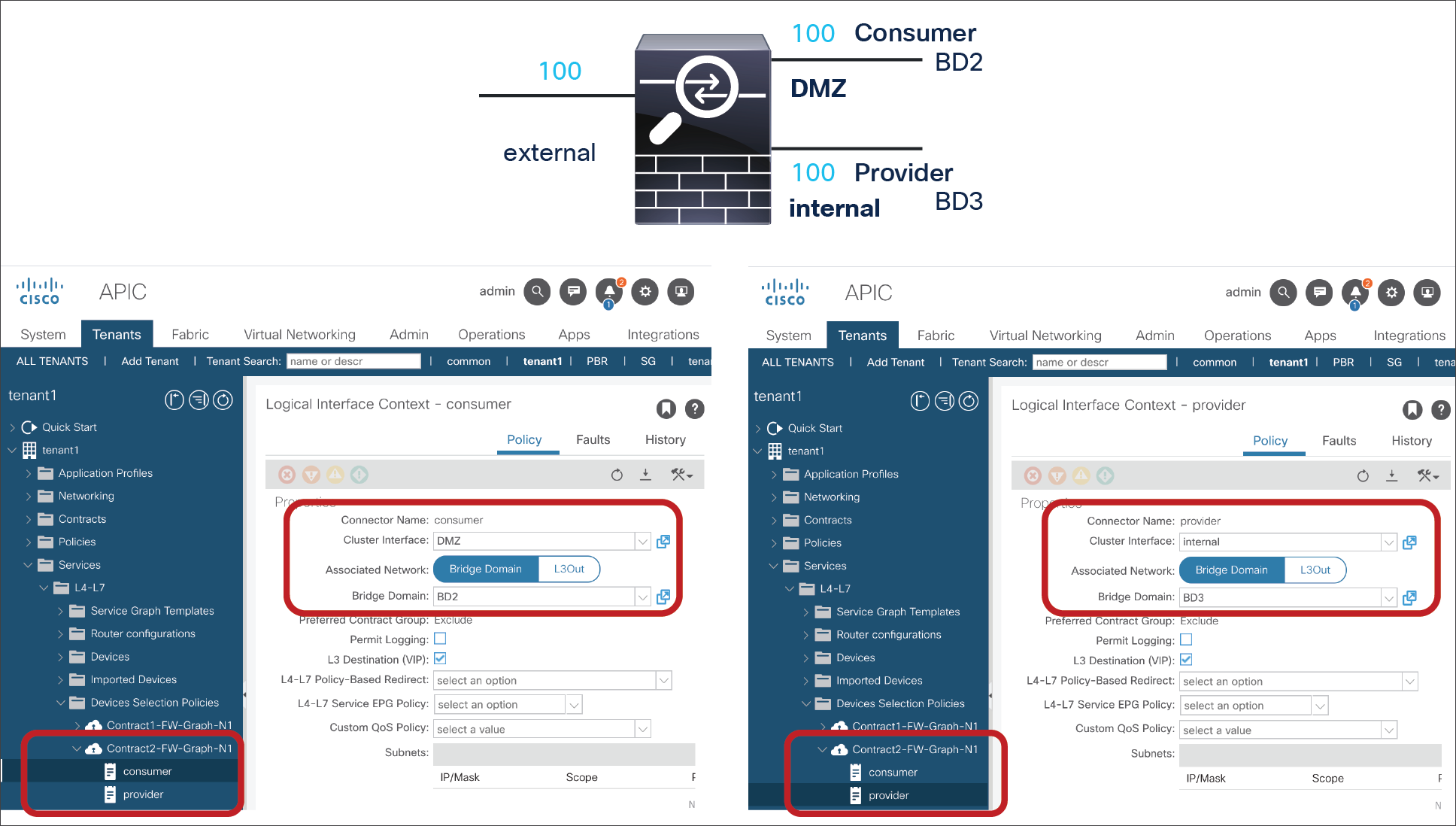
Device Selection Policy for Contract2 (virtual appliance)
Example 3: Physical L4-L7 appliance, shared consumer interface, VLAN trunking
The contract design in this example is the same as Example 1 (Figure 58), but the L4-L7 device is in a physical domain or in a virtual domain with “Trunking Port” enabled. In this case, you don’t have to add multiple concrete interfaces because you can use VLAN trunking. If the bridge domain for the service device connector is different from the bridge domain for other connectors of the service node, a different cluster interface is required.
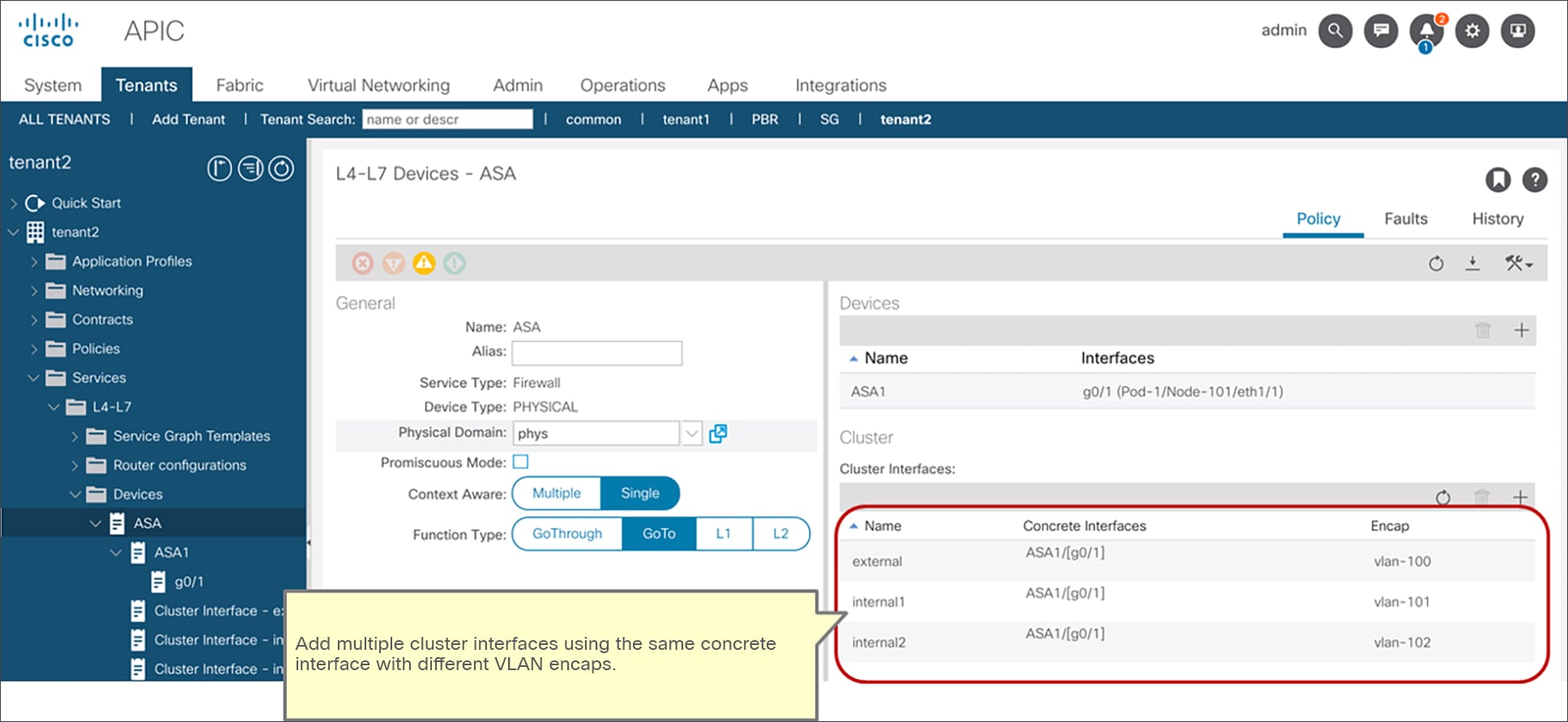
Cluster interface (physical appliance)
In this example, you use the same concrete interface for both contracts with the service graph, but the bridge domain (BD) for the provider connector is different for each contract with the service graph, so the use of a different cluster interface on the service device is required (Figures 67 and 68):
● Contract1 with Service-Graph uses cluster interface “external” as the consumer connector and “internal1” as the provider connector. The provider side is BD2.
● Contract2 with Service-Graph uses cluster interface “external” as the consumer connector and “internal2” as the provider connector. The provider side is BD3.
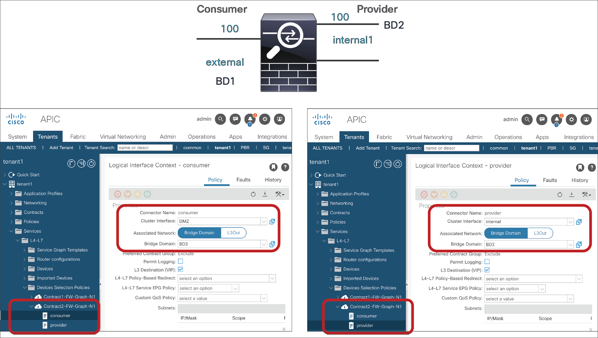
Device selection policy for Contract1 (physical appliance)
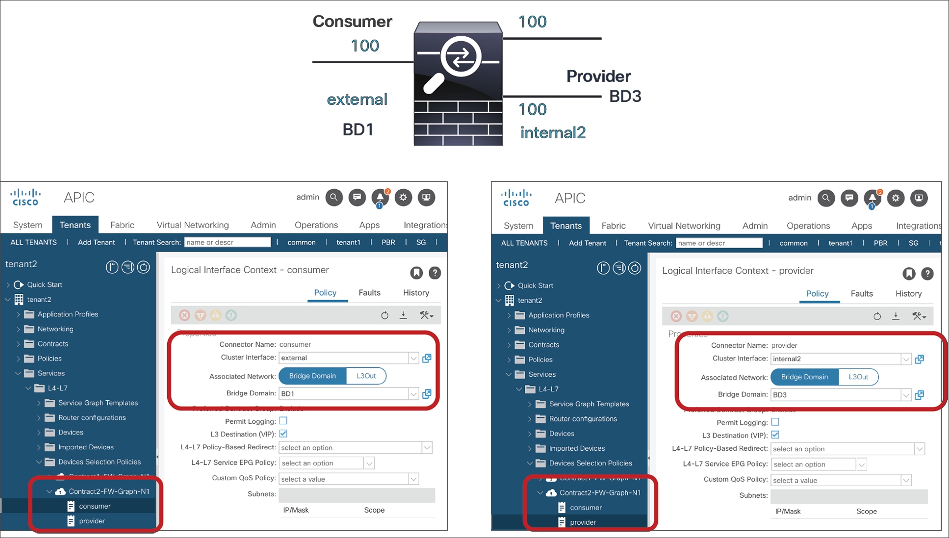
Device selection policy for Contract2 (physical appliance)
In this case, a total of three interfaces using VLAN encaps defined in the L4-L7 device are created as the three shadow EPGs in the same service device (Figure 69). The VLANs are the ones defined in the L4-L7 device (Figure 66).
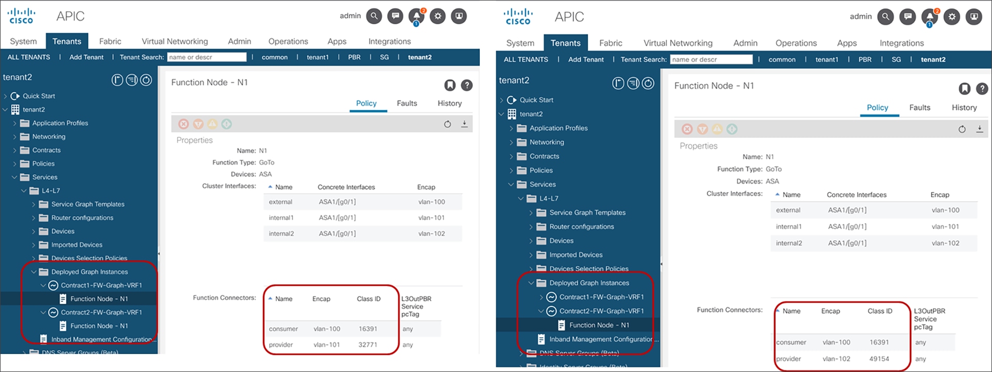
Deployed device
Example of configuration of a service graph with ASA in transparent mode
This section provides an example that shows how to deploy a service graph with a Cisco ASA firewall. The previous sections presented the steps for configuring an L4-L7 service graph common to all L4-L7 services and that also applies to the ASA firewall. This section complements the previous sections by describing a complete configuration of a service graph with an ASA firewall in transparent mode.
Note: The configuration of the firewall itself is outside the scope of this document.
Figure 70 illustrates the deployment example.
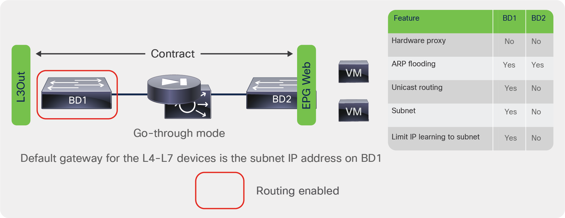
Cisco ASA deployed in transparent mode
Fabric and access policy configuration
Perform the following steps in Cisco ACI:
● If you are using a physical ASA device, define the physical domain for the ASA ports with a static VLAN pool.
● If you are using ASAv, define the virtual domain with a dynamic VLAN pool.
As with the other Cisco ACI configurations, you should define the Attachable Entity Profile (AEP), the policy group, and so on.
If you are using a physical ASA, you likely will want to use a vPC to connect it to Cisco ACI. In this case, you need to create a policy group type of vPC.
Data path configuration for transparent mode
As previously explained, you need to configure the data path for transparent mode as follows:
● Create two bridge domains.
● Configure unknown unicast flooding, ARP flooding, and unicast routing as necessary.
The following list shows the configurations for an ASA deployed in transparent mode:
● Bridge domain outside or client facing (consumer side)
◦ Enable unicast routing.
◦ Enable unknown unicast flooding.
◦ Enable ARP flooding.
◦ The subnet definition on the bridge domain is the default gateway for the servers.
● Bridge domain internal or server facing (provider side):
◦ Disable unicast routing.
◦ Enable unknown unicast flooding.
◦ Enable ARP flooding.
◦ The subnet definition on the bridge domain is irrelevant.
You need to associate both bridge domains with a VRF instance to make the Cisco ACI object model consistent.
You then create EPGs for the client and server sides, create a service graph template, and apply the template to the contract between the EPGs.
After you apply the service graph template, if you expect the outside bridge domain to perform the default gateway function for the firewall, you need to change the adjacency type for the connector of the external interface of the ASA to Layer 3. You also need to enable unicast routing. You need to take these steps to bring up the switch virtual interface (SVI) on the bridge domain (Figure 71).
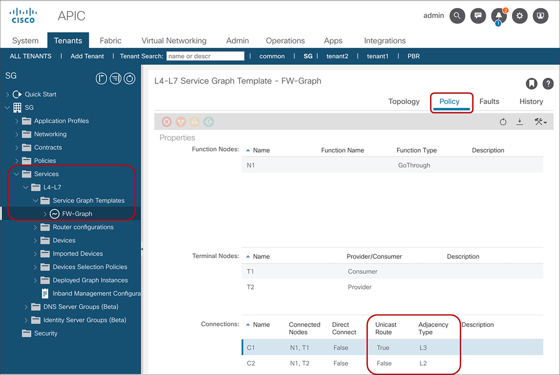
Configuration of the Layer 3 connector
XML configuration for Cisco ASAv deployed in transparent mode
This section shows the XML configuration for the ASAv deployed in transparent mode.
Creating the tenant
<polUni>
<fvTenant name="Sales">
<!-- Creates VRF -->
<fvCtx name="Salesctx1"/>
<!-- bridge domain -->
<fvBD name="SalesBDOutside" arpFlood="yes" unicastRoute="yes" unkMacUcastAct="flood" unkMcastAct="flood">
<fvRsCtx tnFvCtxName="Salesctx1" />
<fvSubnet ip="30.0.0.2/24" />
</fvBD>
<!-- bridge domain -->
<fvBD name="SalesBDInside" arpFlood="yes" unicastRoute="no" unkMacUcastAct="flood" unkMcastAct="flood">
<fvRsCtx tnFvCtxName="Salesctx1" />
</fvBD>
<fvAp name="orderingtool">
<fvAEPg matchT="AtleastOne" name="app" >
<fvRsDomAtt instrImedcy="lazy" resImedcy="immediate" tDn="uni/vmmp-VMware/dom-vDS-rackA1">
</fvRsDomAtt>
<fvRsBd tnFvBDName="SalesBDInside"/>
</fvAEPg>
</fvAp>
</fvTenant>
</polUni>
Creating the contract
<polUni>
<fvTenant dn="uni/tn-Sales" name="Sales">
<!-- setting scope to Tenant: the contract can also be used across VRFs if needed -->
<vzBrCP name="webtoapp" scope="tenant">
<vzSubj name="alltraffic" provMatchT="AtleastOne" revFltPorts="yes">
<vzRsSubjFiltAtt tnVzFilterName="default"/>
</vzSubj>
</vzBrCP>
<fvAp name="orderingtool">
<fvAEPg matchT="AtleastOne" name="app">
<fvRsProv tnVzBrCPName="webtoapp"/>
</fvAEPg>
</fvAp>
<l3extOut name="Internet">
<!-- Definition of the external EPG -->
<!-- The External EPG Consumes the Contract provided by EPG app -->
<l3extInstP matchT="AtleastOne" name="InternetEPG">
<fvRsCons tnVzBrCPName="webtoapp"/>
</l3extInstP>
</l3extOut>
</fvTenant>
</polUni>
Creating Concrete Device (CDev) and L4-L7 Device (LDev)
<polUni>
<fvTenant name="Sales">
<!-- Definition of the logical device, i.e. the cluster of ASA -->
<vnsLDevVip contextAware="single-Context" devtype="VIRTUAL" name="ASAv01-cluster" funcType="GoThrough" managed="no" svcType="FW">
<!-- This specifies the VMM domain to use -->
<vnsRsALDevToDomP tDn="uni/vmmp-VMware/dom-vDS-rackA1"/>
<!-- ASA-1 is the name that you give to the configuration for one device -->
<!-- It is referenced by lDevVip-ASAv01-cluster/cDev-ASA-1/cIf-*** -->
<!-- If this cfg had two devices in the cluster you would have another similar cfg -->
<!-- vsphere6-5-A1 is the name of the vCenter host -->
<!-- the vmNAME is the name of the ASA virtual appliance -->
<vnsCDev devCtxLbl="" name="ASA-1" vcenterName="vCenterACI2" vmName="ASAv">
<vnsRsCDevToCtrlrP tDn="uni/vmmp-VMware/dom-vDS-rackA1/ctrlr-vsphere6-5-A1" userdom="all"/>
<!-- Network Adapter 1 is used for Management -->
<!-- so the list here starts from Network Adapter 2 -->
<!-- This is telling ACI that int Network Adapter 2 is mapped to Gig0/0 in ASA -->
<vnsCIf name="GigabitEthernet0/0" vnicName="Network adapter 2"/>
<!-- This is telling ACI that int Network Adapter 3 is mapped to Gig0/1 in ASA -->
<vnsCIf name="GigabitEthernet0/1" vnicName="Network adapter 3"/>
</vnsCDev>
<!-- The logical intf is the abstraction of the intf that represents the cluster -->
<!-- in the case of a cluster with a single device, the logical intf includes -->
<!-- the intf of the "concrete" device -->
<vnsLIf name="ASAClusterExt">
<!-- lDevVip-ASAv01-cluster uses the name of the LDev that you previously defined -->
<vnsRsCIfAtt tDn="uni/tn-Sales/lDevVip-ASAv01-cluster/cDev-ASA-1/cIf-[GigabitEthernet0/0]"/>
</vnsLIf>
<vnsLIf name="ASAClusterInt">
<!-- lDevVip-ASAv01-cluster uses the name of the LDev that you previously defined -->
<vnsRsCIfAtt tDn="uni/tn-Sales/lDevVip-ASAv01-cluster/cDev-ASA-1/cIf-[GigabitEthernet0/1]"/>
</vnsLIf>
</vnsLDevVip>
</fvTenant>
</polUni>
Creating the service graph template
<polUni>
<fvTenant name="Sales">
<!-- This is the name of the graph -->
<!-- it is referenced when you associate with the contract -->
<vnsAbsGraph name="FW-bridged">
<!-- This is the Outside "connector" of the graph -->
<!-- The name is referenced by AbsTermNodeProv-ServerSide/AbsTConn -->
<vnsAbsTermNodeCon name="OutsideTerminalConnector">
<vnsAbsTermConn attNotify="no" name="1"/>
<vnsInTerm name="input-terminal"/>
<vnsOutTerm name="output-terminal"/>
</vnsAbsTermNodeCon>
<!-- This is the Inside "connector" of the graph -->
<!-- The name is referenced by AbsTermNodeCon-ClientSide/AbsTConn -->
<vnsAbsTermNodeProv name="InsideTerminalConnector">
<vnsAbsTermConn attNotify="no" name="1" />
<vnsInTerm name="input-terminal"/>
<vnsOutTerm name="output-terminal"/>
</vnsAbsTermNodeProv>
<!-- This defines the name of the node in the graph -->
<!-- The name is referenced by "AbsNode-ASA-1-node/AbsFConn-****" -->
<vnsAbsNode funcTemplateType="FW_TRANS" funcType="GoThrough" name="ASA-1-node">
<!-- This is the name of the connectivity point of the node -->
<!-- the name is referenced by AbsNode-ASA-1-node/AbsFConn-ASAnodeoutside -->
<vnsAbsFuncConn attNotify="no" name="ASAnodeoutside">
</vnsAbsFuncConn>
<!-- This is the name of the connectivity point of the node -->
<!-- the name is referenced by "AbsNode-ASA-1-node/AbsFConn-ASAnodeinside" -->
<vnsAbsFuncConn attNotify="no" name="ASAnodeinside">
</vnsAbsFuncConn>
</vnsAbsNode>
<!-- This cfg makes it possible to enable routing on the BD that it connects to -->
<vnsAbsConnection adjType="L3" connType="external" name="ArbitraryName1" unicastRoute="yes">
<vnsRsAbsConnectionConns tDn="uni/tn-Sales/AbsGraph-FW-bridged/AbsNode-ASA-1-node/AbsFConn-ASAnodeoutside"/>
<vnsRsAbsConnectionConns tDn="uni/tn-Sales/AbsGraph-FW-bridged/AbsTermNodeCon-OutsideTerminalConnector/AbsTConn"/>
</vnsAbsConnection>
<vnsAbsConnection adjType="L2" connType="external" name="ArbitraryName2" unicastRoute="no">
<vnsRsAbsConnectionConns tDn="uni/tn-Sales/AbsGraph-FW-bridged/AbsNode-ASA-1-node/AbsFConn-ASAnodeinside"/>
<vnsRsAbsConnectionConns tDn="uni/tn-Sales/AbsGraph-FW-bridged/AbsTermNodeProv-InsideTerminalConnector/AbsTConn"/>
</vnsAbsConnection>
</vnsAbsGraph>
</fvTenant>
</polUni>
Configuring device selection policy
<polUni>
<fvTenant name="Sales">
<!-- here we need to match the contract name -->
<!-- the graph name -->
<!-- the node name in the graph -->
<!-- and indicate which interface maps to which BD -->
<!-- nodeNameOrLbl refers to the name of the node as defined the Abstract Graph -->
<vnsLDevCtx ctrctNameOrLbl="webtoapp" graphNameOrLbl="FW-bridged" nodeNameOrLbl="ASA-1-node">
<!-- ASAv01-cluster is the name of the Logical Device i.e. of the Cluster of ASAv -->
<vnsRsLDevCtxToLDev tDn="uni/tn-Sales/lDevVip-ASAv01-cluster"/>
<!-- Connector name is defined in the Abstract Graph -->
<!-- It is the function connector -->
<vnsLIfCtx connNameOrLbl="ASAnodeoutside" name="line1">
<!-- ASAv01-cluster is the name of the Logical Device -->
<!-- The Lif is the "cluster" interface name, i.e. the abstract interface -->
<!-- that can map to either ASAv in the cluster -->
<vnsRsLIfCtxToLIf tDn="uni/tn-Sales/lDevVip-ASAv01-cluster/lIf-ASAClusterExt"/>
<!-- This is the outside BD-->
<vnsRsLIfCtxToBD tDn="uni/tn-Sales/BD-SalesBDOutside"/>
</vnsLIfCtx>
<vnsLIfCtx connNameOrLbl="ASAnodeinside" name="line2">
<vnsRsLIfCtxToLIf tDn="uni/tn-Sales/lDevVip-ASAv01-cluster/lIf-ASAClusterInt"/>
<vnsRsLIfCtxToBD tDn="uni/tn-Sales/BD-SalesBDInside"/>
</vnsLIfCtx>
</vnsLDevCtx>
</fvTenant>
</polUni>
Attaching the graph to the contract
<polUni>
<fvTenant name="Sales">
<vzBrCP name="webtoapp">
<vzSubj name="alltraffic" provMatchT="AtleastOne" revFltPorts="yes">
<vzRsSubjFiltAtt tnVzFilterName="default"/>
<vzRsSubjGraphAtt tnVnsAbsGraphName="FW-bridged"/>
</vzSubj>
</vzBrCP>
</fvTenant>
</polUni>
Cisco ACI enables you to automate the provisioning of L4-L7 network connectivity in the data center. It also enables you to insert L4-L7 devices in the traffic path while keeping the Cisco ACI fabric as the default gateway for the servers.
These functions can be implemented using the GUI or programmatically in Python and can be automated using the REST API.
For more information about Cisco ACI and service graphs, please refer to:
● https://www.cisco.com/go/aci
● https://www.cisco.com/c/en/us/solutions/data-center-virtualization/unified-fabric/aci_ecosystem.html