Cisco Application Centric Infrastructure Policy-Based Redirect Service Graph Design White Paper
Available Languages
Bias-Free Language
The documentation set for this product strives to use bias-free language. For the purposes of this documentation set, bias-free is defined as language that does not imply discrimination based on age, disability, gender, racial identity, ethnic identity, sexual orientation, socioeconomic status, and intersectionality. Exceptions may be present in the documentation due to language that is hardcoded in the user interfaces of the product software, language used based on RFP documentation, or language that is used by a referenced third-party product. Learn more about how Cisco is using Inclusive Language.
Cisco Application Centric Infrastructure (Cisco ACI) technology provides the capability to insert Layer 4 through Layer 7 (L4-L7) functions using an approach called a service graph. One of the main features of the service graph is Policy-Based Redirect (PBR).
With PBR, the Cisco ACI fabric can redirect traffic between security zones to L4-L7 devices, such as a firewall, Intrusion-Prevention System (IPS), or load balancer, without the need for the L4-L7 device to be the default gateway for the servers or the need to perform traditional networking configuration such as Virtual Routing and Forwarding (VRF) sandwiching or VLAN stitching. Cisco ACI can selectively send traffic to L4-L7 devices based, for instance, on the protocol and the Layer 4 port. Firewall inspection can be transparently inserted in a Layer 2 domain with almost no modification to existing routing and switching configurations.
This document provides PBR service graph design and configuration guidance using a variety of use cases and options.
This document assumes that the reader has a basic knowledge of Cisco ACI and service graphs and how these work. For more information, see the Cisco ACI white papers available at Cisco.com: https://www.cisco.com/c/en/us/solutions/data-center-virtualization/application-centric-infrastructure/white-paper-listing.html.
This document uses the following terms with which you must be familiar:
● BD: Bridge domain
● EPG: Endpoint group
● Class ID: Tag that identifies an EPG
● Policy: In Cisco ACI, “policy” can mean configuration in general, but in the context of this document, “policy” refers specifically to the Access Control List (ACL)–like Ternary Content-Addressable Memory (TCAM) lookup used to decide whether a packet sourced from one security zone (EPG) and destined for another security zone (EPG) is permitted, redirected, or dropped
● PBR node: L4-L7 device that is used for a PBR destination
● Consumer connector: PBR node interface facing the consumer side
● Provider connector: PBR node interface facing the provider side
In a Cisco ACI fabric, traffic is routed and bridged based on the destination IP and MAC addresses, the same as in traditional networks. This process is the same, by default, when you use service graphs. Thus, you still must consider routing and bridging design for service device insertion. However, with Cisco Application Policy Infrastructure Controller (APIC) Release 2.0(1m) and later, service graphs provide the PBR feature to redirect traffic between different security zones. The use of PBR simplifies service device insertion and removal.
For example, Figure 1 illustrates the difference between a routing-based design (a classic VRF sandwich) and PBR in Cisco ACI. In a routing-based design, Layer 3 outside (L3Out) connections are established between the fabric and the internal and external firewall interfaces. A classic VRF sandwich configuration hence must enforce traffic through the routed firewall: the web subnet and the IP subnet of the firewall internal interface are associated with a firewall inside VRF2 instance. The firewall outside interface and the Layer 3 interface facing the WAN edge router are instead part of a separate firewall outside VRF1 instance. Otherwise, traffic is carried directly between two endpoints, because the destination endpoint IP address can be resolved in the VRF instance.
The use of PBR simplifies configuration, because the previously described VRF sandwich configuration is now not required to insert a Layer 3 firewall between security zones. The traffic instead is redirected to the node based on the PBR policy.
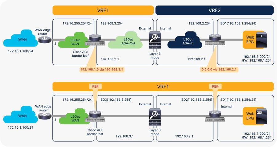
Comparison: VRF sandwich design and PBR design
PBR requires a service graph attached to the contract between endpoint groups (EPGs). Traffic redirection is based on the source EPG, destination EPG, and filter (protocol, source Layer 4 port, and destination Layer 4 port) configuration in the contract.
For example, if you have Contract-A with a PBR service graph between the L3Out EPG and EPG-A, only the traffic between the L3Out EPG subnet and an endpoint in EPG-A will be redirected to service node FW1. If you have another EPG, EPG-B, that uses another contract, Contract-B, to communicate with the same L3Out interface, you can configure a different action, such as redirection to a different service node, FW2, or traffic forwarding to the L3Out interface directly (Figure 2).
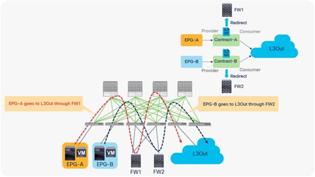
Example: Use of different PBR policy based on the source and destination EPG combination
In addition, you can use different filters in a contract to send traffic to different L4-L7 devices. In Cisco ACI, filters are organized into subjects, and a contract is a collection of subjects. The service graph always is deployed by applying it to a subject under a contract. If you have Contract1 that has Subject1 that permits HTTP with a PBR service graph and Subject2 that permits all without a PBR service graph, only HTTP traffic will be redirected. A typical use case is the insertion of an IPS or Deep Packet Inspection (DPI) device that needs to examine the data inside a packet. If the data is encrypted, redirecting the traffic to an IPS would just consume service device resources without any benefit. With service graph redirection, you can configure the contract to redirect only the unencrypted traffic (Figure 3).
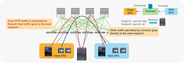
Example: Use of different PBR policy based on the contract filter
Requirements and design considerations
This section presents the requirements and design considerations for Cisco ACI PBR. Note that this document refers to a service graph device with the PBR feature as a PBR node, and it refers to a bridge domain that contains a PBR node interface as a PBR node bridge domain.
The main Cisco ACI PBR capabilities are as follows:
● PBR works with both physical and virtual service appliances.
● PBR works with service graphs in both managed mode (service-policy mode) and unmanaged mode (network-policy mode).
● PBR works with both bidirectional and unidirectional contracts.
● PBR can be used between L3Out EPG and EPGs, between EPGs, and between L3Out EPGs. PBR is not supported if L2Out EPG is part of the contract.
● PBR is supported in Cisco ACI Multi-Pod, Multi-Site, and Remote Leaf environments.
● The load can be distributed across multiple L4-L7 devices (symmetric PBR).
The main use cases for Cisco ACI PBR are as follows:
● Use PBR to insert firewalls or load balancers in the path between endpoints while keeping the default gateway on the Cisco ACI fabric to use distributed routing.
● Use PBR to insert an L4-L7 device in the path between endpoints that are in the same subnet.
● Use PBR to send traffic selectively to L4-L7 devices based on protocol and port filtering.
● Use Symmetric PBR to horizontally scale the performance of L4-L7 devices.
The main requirements for Cisco ACI PBR with routed mode device (L3 PBR) are as follows:
● You should use Cisco APIC Release 2.0(1m) or later.
● The Cisco ACI fabric must be the gateway for the servers and for the PBR node.
● The L4-L7 device must be deployed in go-to mode (routed mode).
● PBR node interface must be connected under leaf down link interface, not under FEX host interface. Consumer and Provider endpoint can be connected under FEX host interfaces”.
● PBR node interfaces must be in a bridge domain and not in an L3Out. For releases newer than APIC Release 5.2, this requirement is not mandatory for L3 PBR. The L3 PBR node interface can be in an L3Out.
● The PBR node bridge domain must not be the consumer or provider bridge domain. Therefore, you need a dedicated service bridge domain. For releases later than APIC Release 3.1, this requirement is not mandatory. The PBR node bridge domain can be the same as the consumer or provider bridge domain.
● Prior to APIC Release 3.1, the admin needed to disable Dataplane learning for the bridge domain where the PBR node is attached. For releases later than APIC Release 3.1 with Cisco Nexus 9300-EX and -FX platform leaf switches onward, there is no need for the admin to disable dataplane IP learning for the BD where the PBR node interface is attached.
● The administrator must enter the PBR node IP address and MAC address in the APIC configuration. For releases later than APIC Release 5.2, the MAC address configuration is not mandatory for L3 PBR if IP-SLA tracking is enabled.
● Symmetric PBR (more than one PBR destination per PBR policy) requires Cisco Nexus 9300-EX and -FX platform leaf switches onward.
● The PBR node bridge domain and the L3Out for PBR node must belong to the same VRF instance as either the consumer bridge domain (EPG) or provider bridge domain (EPG).
Design considerations for Cisco ACI PBR with routed mode device (L3 PBR) include the following:
● If the fabric consists of first-generation Cisco Nexus 9300 platform switches such as Cisco Nexus 93128TX, 93120TX, 9396TX, 9396PX, 9372PX, 9372PX-E, 9372TX and 9372TX-E, the PBR node must not be under the same leaf node as either the consumer or provider EPG.
● Prior to APIC Release 5.2, which does not support dynamic PBR destination MAC address detection, in a high-availability active/standby deployment, you need to configure the L4-L7 device with a virtual IP and virtual MAC address. A virtual IP and virtual MAC address is defined as a floating IP and MAC address that, when the active L4-L7 node goes down, is taken over by the standby node.
● It’s recommended to enable GARP-based detection on the PBR node bridge domain because GARP is commonly used for L4-L7 device failover.
● If PBR nodes exchange link-local multicast packets such as HSRP, VRRP and IPv6 NS, each PBR node pair that is supposed to exchange the link-local multicast packets must be under different leaf due to CSCvq57414 and CSCvq76504.
● Prior to APIC Release 3.2, PBR can be used for only one node of a service graph. For releases later than APIC Release 3.2, PBR can be used for multiple nodes of a service graph.
● Prior to APIC Release 3.2, PBR was not supported for Cisco ACI Multi-Site environments. (PBR was not supported in the contract between EPGs in different sites.) For APIC Release 3.2, the one-node Firewall PBR is supported in Cisco ACI Multi-Site environments. The two-node PBR service graph, for example Firewall and Load Balancer, is supported in APIC Release 4.0.
● Prior to APIC Release 3.2, you cannot associate a service graph with PBR with a contract with vzAny as provider. For releases later than APIC Release 3.2, PBR with a contract with vzAny as provider is supported. Note that vzAny cannot be provider for an inter-VRF contract regardless with or without a service graph.
● Prior to APIC Release 4.0, you could not associate a service graph with an intra-EPG contract. For releases later than APIC Release 4.0, PBR with an intra-EPG contract is supported. Starting with APIC Release 5.2 onward, PBR with an intra Ext-EPG contract is supported.
Starting from APIC Release 4.1, PBR can be used with L1 or L2 devices; for example, inline IPS, transparent firewall (FW), etc. The main requirements for Cisco ACI with L1/L2 mode device (L1/L2 PBR) are as follows:
● You should use APIC Release 4.1 or later.
● L1/L2 PBR requires Cisco Nexus 9300-EX and -FX platform leaf switches onward.
● The Cisco ACI fabric must be the gateway for the servers and for the PBR node.
● The L4-L7 device must be deployed as L1 or L2 mode in physical domain.
● L1/L2 PBR node interfaces must be in a bridge domain and not in an L3Out. The PBR node bridge domain must be a dedicated BD that cannot be shared with other endpoints or other L4-L7 devices’ interfaces.
● The PBR node bridge domain must belong to the same VRF instance as either the consumer bridge domain (EPG) or provider bridge domain (EPG).
● L1/L2 device must be in two-arm mode. The consumer and provider connectors of the L1/L2 device must be in different BDs.
● Consumer and provider connectors of the L1 device must be connected to different leaf nodes. Per port VLAN is not supported. The L2 device doesn’t have this consideration.
Design considerations for Cisco ACI with an L1/L2 mode device (L1/L2 PBR) include the following:
● L1/L2 PBR is supported with unmanaged mode Service Graph only.
● L2 Unknown Unicast option in the service bridge domains must be set to Hardware Proxy for L1/L2 PBR.
● Prior to APIC Release 5.0, L1/L2 PBR supports active/standby mode only. When using ACI version prior to ACI Release 5.0, there is no support for active/active deployment with L1/L2 PBR, unlike L3 PBR. This means that you can configure up to two L1/L2 destinations (meaning up to two L4/L7 devices) per PBR destination group. More than two L4/L7 devices in the same PBR destination group are not supported in APIC Release 4.1 and 4.2. The PBR tracking is required for active/standby mode. As active/active is not supported, the threshold is not applicable. The down action is denied when tracking is enabled. A down action permit cannot be set in APIC Release 4.1.
● Starting from APIC Release 5.0, L1/L2 PBR also supports active/active Symmetric PBR deployment. Symmetric PBR related features such as threshold, down action and backup PBR policy (N+M high availability) are also supported in APIC Release 5.0. For L1 PBR active/active mode, consumer and provider interfaces of each L4-L7 device (aka as consumer and provider connectors) must be in different physical domains.
● Note: Multiple active/standby pairs with L1/L2 PBR active/active design is not supported with backup PBR policy.
● L2 Ping (Ethertype 0x0721) is used for tracking. L2 Ping is exchanged between leaf nodes, which is going through the service device. Thus, the L4-7 device operating in L1/L2 mode needs to permit Ethertype 0x0721.
● If intermediate switch is connected between leaf port and L1/L2 PBR destination, the intermediate switch must be able to carry the traffic with the PBR destination MACs. Static MAC configuration or promiscuous mode configuration might be required on the intermediate switch in addition to permitting Ethertype 0x0721 to permit L2 Ping.
● L1/L2 PBR can be used with Multi-Pod, Multi-Site, and Remote Leaf deployments. For L1/L2 PBR active-active design, PBR destinations can’t be connected to remote leaf as Flood in Encap is not supported on remote leaf. Provider and consumer can still be connected to remote leaf.
● Multinode PBR is supported. The L4-L7 devices operating in L1/L2 mode and L3 mode can be mixed in a service graph.
● PBR with vzAny or intra-EPG contract is not supported as it requires one-arm mode.
Design considerations for Cisco ACI PBR that are applicable to both L1/L2 PBR and L3 PBR include the following:
● Multicast and broadcast traffic redirection are not supported because the contract is applied to unicast traffic only.
● User-defined contract actions, such as redirect, copy, and deny, cannot be applied to specific types of packets. See the frequently asked questions (FAQ) in the ACI Contract Guide for more details.
● PBR is not supposed to be applied to non-IP traffic and control plane traffic such as ARP, ND-Sol ICMPv6 and ND-Advt ICMPv6 traffic. Thus, a common default filter that includes ARP, ethernet traffic, and other non-IP traffic should not be used for PBR. One of the examples is described later in this document. In case of IPv6 traffic, you need to make sure ND-Sol ICMPv6 and ND-Advt ICMPv6 traffic are excluded from a contract subject with PBR even if you use non-default filter because IP and IPv6 ethertypes include ICMPv6.
● Stateful Service device is supposed to be inserted for both consumer to provider and provider to consumer directions. For example:
◦ Firewall (or a device that doesn’t perform IP translation) is inserted by using PBR for both directions.
◦ Load Balancer (or a device that performs IP translation) is inserted by using unidirectional PBR and the fact that the destination IP (VIP or NAT’d IP) for the other direction is owned by the device.
● Although each service device model has different HA/clustering mechanism, it’s generally recommended to use separate segments (BDs) for HA/clustering communication and data traffic where PBR is enforced.
● It’s generally recommended to use vzAny contract to enable PBR for many EPGs to many EPGs traffic instead of many EPGs consuming and providing the same contract.*
● PBR can be applied to bridged traffic as well, where source and destination endpoints are in the same subnet if they are in an L3 bridge domain. Even though source and destinations are in the same subnet, the original source MAC is not preserved and TTL is decremented because ACI fabric routes traffic when PBR policy is applied (ACI fabric rewrites the destination MAC address to the PBR destination MAC address, which means routing).
● PBR is not supported for traffic that includes Out-of-Band Management EPG or In-Band Management EPG regardless it’s in predefined oob VRF, inb VRF or user defined VRF because only permit and deny contract actions are supported for the Management EPGs.
● L4-L7 devices (also referred to as PBR destinations or PBR nodes) used in the same service graph must not be distributed between remote leaf nodes and the main location.
● If multiple PBR policies have the same PBR destination IP in the same VRF, it must use the same IP-SLA policy, health-group, and Pod-ID-aware redirection configurations for the PBR destination. This is because the PBR destination uses (VRF, IP) as the key for tracking status and configuration. Examples are described later in this document.
● TCAM Compression (“Enable Policy Compression” formerly known as “no stats” option in the contract filter) does not take effect on a zoning rule with a redirect rule. This means that the ability to optimize TCAM utilization with contracts/filters doesn’t apply for contract/filter rules that are used for the purpose of service graph redirection (PBR).
● Starting from APIC Release 4.2(6) and 5.0(1), contract inheritance with service graph is supported if the contract and EPGs are in the same tenant.
● The use of copy service with a PBR node in the same service graph is not supported.
*Note: It is because a possible impact on changing a configuration on a contract that has many provider and consumer EPGs. If one configuration change on APIC is related to multiple zoning-rule changes at the same time, it would take time to finish programming the hardware of a give leaf node.
Please see the Scalability Consideration section in ACI Contract Guide.
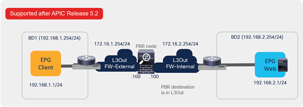
Starting from APIC Release 5.2, L3 PBR destinations can be in an L3Out instead of an L3 bridge domain. The main requirements for PBR destinations in an L3Out are:
● You should use APIC Release 5.2 or later.
● The L3Out for the PBR destinations must belong to the same VRF instance as either the consumer bridge domain (EPG) or provider bridge domain (EPG).
● IP-SLA Tracking is mandatory.
● An L3Out EPG with 0.0.0.0/0 or 0::0 cannot be used for the L3Out EPG for PBR destinations.
Design considerations for PBR destinations in an L3Out include:
● L3Out with SVI, routed sub-interface, or routed interface are supported. (Infra L3Out, GOLF L3Out, SDA L3Out, or L3Out using floating SVI for a PBR destination are not supported)
● Single pod, Multi-Pod, and Remote Leaf are supported. Multi-Site is not supported as of APIC Release 5.2.
● Multinode PBR is supported.
● If the consumer/provider EPG is an L3Out EPG, it must not be under the same L3Out for PBR destinations.
● If the consumer/provider EPG is an L3Out EPG, it must not be under the service leaf nodes, where the L3Out for PBR destinations resides. If the consumer/provider EPG is a regular EPG-not an L3Out EPG-the consumer, provider, and the L3Out for PBR destinations can be under the same leaf. This consideration is applicable to the case where a consumer/provider EPG communicates with an L3Out EPG for a service device via another service device where PBR destination in an L3Out is enabled. For example, PBR destination in an L3Out is enabled on the firewall to redirect traffic between the consumer EPG and the VIP of the load balancer behind the L3Out:
◦ Two node service graph that has a firewall as the first node and a load balancer as the second node.
◦ The firewall and the load balancer are connected via L3Outs: L3Out-FW and L3Out-LB.
◦ The traffic between the consumer EPG and the VIP of the load balancer hits this consideration because PBR destination in an L3Out is enabled for the traffic between the consumer EPG and the VIP (L3Out-LB EPG). L3Out-FW and L3Out-LB must not be under the same leaf nodes.
● If the service device is in two-arm mode and one of the L3Outs for the PBR destinations learns 0.0.0.0/0 or 0::0 route, both arms of the service device must be connected to the same leaf node or the same vPC pair.
● Mixing of PBR destinations in an L3 bridge domain and PBR destinations in an L3Out within the same function node in the service graph is not supported. For example:
◦ These configurations are not supported:
◦ Consumer connector of Function Node1 is in BD1 (PBR is enabled)
◦ Provider connector of Function Node1 is in an L3Out1 (PBR is enabled)
◦ These configurations are supported:
◦ Consumer connector of Function Node1 is in BD1 (PBR is NOT enabled)
◦ Provider connector of Function Node1 is in an L3Out1 (PBR is enabled)
● The inter-VRF contract has the following considerations:
◦ EPG contract: If the L3Out for a PBR destination is in the provider VRF for inter-VRF contracts, the L3Out EPG subnet must be leaked to the consumer VRF. Otherwise, the consumer VRF doesn’t have the route to the PBR destination and the provider VRF doesn’t have a permit rule for the traffic from the PBR destination in the provider VRF to the consumer EPG. (In the case of a PBR destination in a BD, the service BD for the PBR destination does not have to be leaked to the consumer VRF.)
◦ ESG contract: Regardless of whether the L3Out EPG is in the consumer or provider VRF, the L3Out EPG subnet must be leaked to the other VRF.
● The Bypass feature has a known caveat: CSCvy31805
● vzAny-to-vzAny contract with PBR destination in an L3Out is supported. Because the L3Out EPG for the PBR destination is also part of the vzAny in the VRF, another contract that has a higher priority than one for vzAny-to-vzAny contract is required to avoid redirecting traffic whose source IP is matched with the L3Out EPG for the PBR destination.
Unless otherwise indicated, topology and design examples in this document shall be examples with L3 PBR.
This document mainly covers single pod design considerations. For Multi-Pod and Multi-Site environment details, please see the Multi-Pod Service integration white paper.
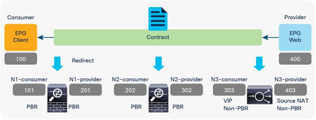
This section shows topology examples for PBR. More information is provided later in this document.
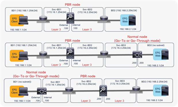
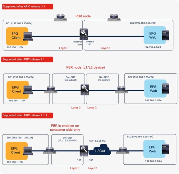
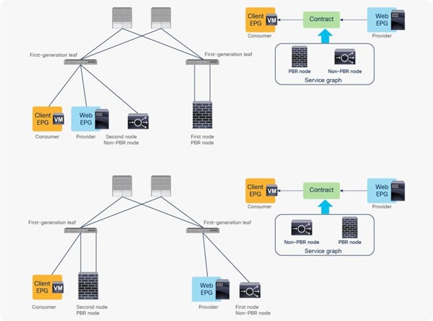
The first example in Figure 4 shows the typical use case of one-node firewall insertion. The PBR node is a Layer 3 node. Prior to APIC Release 3.1, the PBR node bridge domain must not be the consumer or provider bridge domain that contains the consumer or provider EPG. Therefore, a different bridge domain and subnet range were required for the PBR node, such as in Figure 4, below. Starting from APIC Release 3.1, this requirement is no longer mandatory. Please see the section “Design with PBR node and consumer and provider EPGs in the same subnet” for details.
The second and third examples are two-node service graphs. Prior to APIC Release 3.2, if you have a two-node service graph, either the first node or the second node can be a PBR node. A non-PBR node can be in the same bridge domain as the consumer or provider EPG, but prior to APIC Release 3.1, the PBR node must be in a dedicated service bridge domain. The fourth example is PBR node in a nondedicated service bridge domain. Starting from APIC Release 3.2, multimode PBR is introduced. It enables you to use PBR multiple times in a service graph. Please see the section “Multinode service graph with PBR” for details.
The fifth example is L1/L2 PBR. Prior to APIC Release 4.1, PBR node must be an L3 device. Starting from APIC Release 4.1, PBR to an L1/L2 device is introduced Please see the section “L1/L2 PBR” for details.
The sixth example is unidirectional PBR with the other connector in L3Out. Prior to APIC Release 4.1.2, both consumer and provider connectors of a PBR node must be in a bridge domain and not in an L3Out even though PBR is enabled on one of the connectors only. Starting from APIC Release 4.1.2, this requirement is no longer mandatory. L3Out can be used for a connector where PBR is not enabled. Please see the section “Unidirectional PBR with the other connector in L3Out” for details.
The seventh example is PBR destination in an L3Out. Prior to APIC Release 5.2, the PBR destination must be in a bridge domain and not in an L3Out if PBR is enabled on the connector. Starting from APIC 5.2, this requirement is no longer mandatory. L3 PBR destinations can be in an L3Out. See the section, “PBR destination in L3Out”, for more details.
These examples show two-arm-mode PBR nodes, but you can also deploy a one-arm-mode PBR node except in L1/L2 PBR. More information about service graph designs is provided later in this document.
Examples of supported topologies
The PBR node can be between VRF instances or within one of the VRF instances. The PBR node must be in either the consumer or provider VRF instance (Figure 5). For example, you cannot put the PBR node in VRF3, which is neither a consumer nor a provider VRF instance.
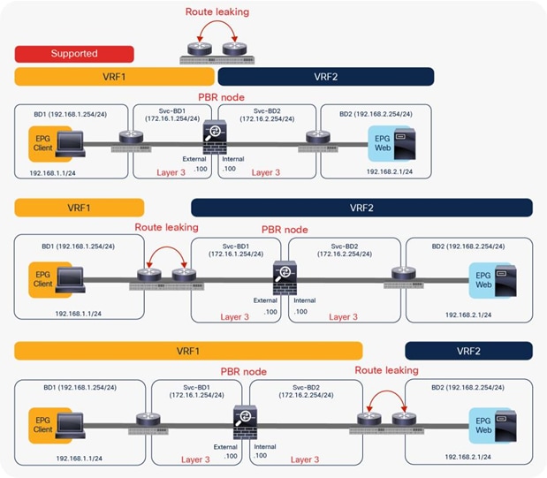
Examples of supported topologies (VRF sandwich design)
Figure 6 shows examples of unsupported topologies. The PBR node must be in an L3 bridge domain, not in an L2 bridge domain.
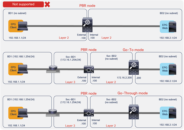
Examples of unsupported topologies (PBR node must be in L3 bridge domain)
Endpoint Dataplane Learning configuration for PBR node
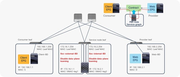
When you deploy a service graph with PBR, the L4-L7 device must be connected to an L3 bridge domain or an L3Out. This bridge domain must be configured with Endpoint Dataplane IP Learning disabled. Figure 8 illustrates this point. This figure depicts bidirectional PBR with the PBR node, a firewall, inserted between the Client and Web EPGs.
This section explains why you must disable Endpoint Dataplane IP Learning for a PBR node bridge domain. It’s not applicable to PBR destinations in an L3Out because IP addresses are not learned from the data plane in an L3Out domain.
PBR design example
The Endpoint Dataplane Learning option is located in Tenants > Networking > Bridge Domains (Figure 8). The default configuration is enabled. The setting enables and disables Endpoint Dataplane IP Learning. Starting from APIC Release 5.0(1), this option is moved under the “Advanced/Troubleshooting” tab within the Policy tab at a bride domain.
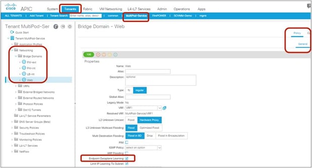
Enable and disable endpoint data-plane learning for the bridge domain
Note: Prior to APIC Release 3.1, disabling the Endpoint Dataplane Learning setting in the PBR node bridge domain was mandatory. After APIC Release 3.1, the configuration in the PBR node bridge domain is not mandatory. The Endpoint Dataplane Learning setting on the PBR node EPG is automatically disabled during service graph instantiation.
The reason that you must disable endpoint data-plane IP learning for a service graph with PBR is that leaf nodes involved in the PBR traffic flow may experience unwanted endpoint learning behavior if you leave the Endpoint Dataplane Learning setting enabled in the PBR node bridge domains.
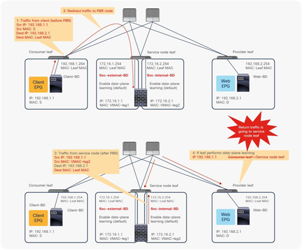
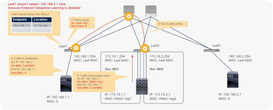
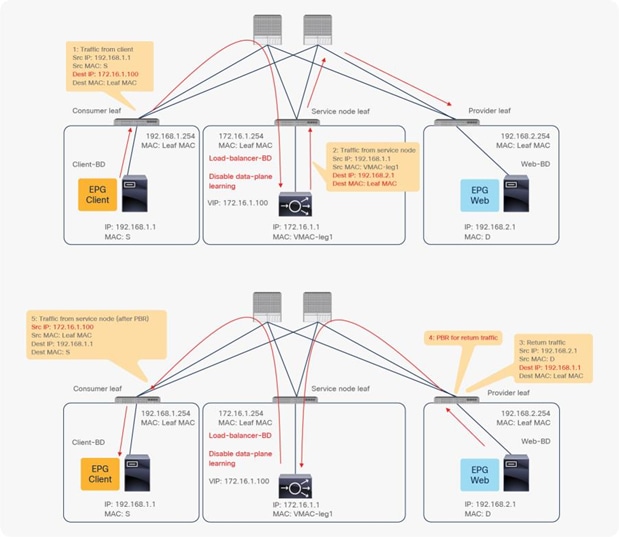
For example, as shown in Figure 9, the source IP address of traffic returning from the PBR node is still 192.168.1.1 even after PBR is enforced. Therefore, the provider leaf node will receive packets with 192.168.1.1 as the inner source IP address and the service node leaf Virtual Extensible LAN (VXLAN) Tunnel Endpoint (VTEP) as the outer source IP address. So the provider leaf node will learn 192.168.1.1 through the service node leaf VTEP IP address, even though 192.168.1.1 is actually under a different leaf node.
If you disable Endpoint Dataplane Learning on Svc-internal-BD, the bridge domain for the provider side of the PBR node, the provider leaf node doesn’t learn 192.168.1.1 through the traffic from the PBR node.
To maintain symmetric traffic, PBR for the return traffic is also required in this example. The Endpoint Dataplane Learning option must be disabled for Svc-external-BD as well to prevent the consumer leaf node from learning 192.168.2.1 through the service leaf node after PBR is enforced.
Why data-plane learning must be disabled in the PBR node bridge domain
Note: Although the provider leaf node does not learn the consumer endpoint, the traffic can be forwarded by using the spine proxy node.
This section explains how a policy is updated in the Cisco ACI fabric when a service graph with PBR is deployed.
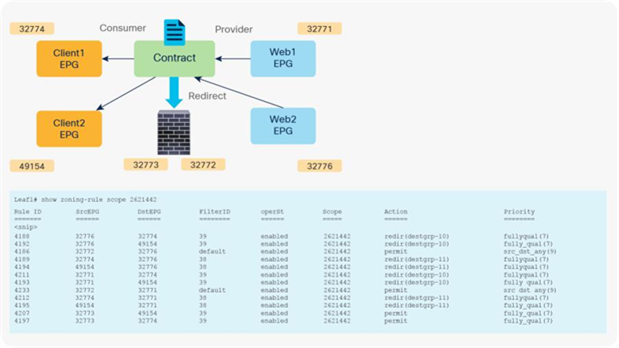
PBR policy is programmed on consumer and provider leaf nodes. For example, if you have consumer, provider, and service leaf nodes as shown in Figure 10, the PBR policy is configured on Leaf1 and Leaf3, but not on Leaf2.
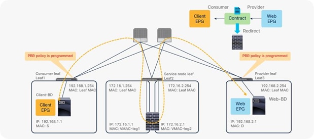
Topology example
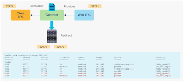
Before a service graph is applied to the contract between the Client EPG (class ID 32774) and the Web EPG (class ID 32771), Permit entries between them are programmed on leaf nodes as shown in Figure 11 and Table 1 (scope ID 2621442 is the VRF ID).
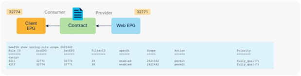
Before service graph is deployed
Table 1. Permit rule without service graph
| Source class ID |
Destination class ID |
Filter ID |
Action |
| 32771 (Web EPG) |
32774 (Client EPG) |
38 (The filter used in the contract subject) |
Permit |
| 32274 (Client EPG) |
32771 (Web EPG) |
39 (The reverse filter of the filter used in the contract subject) |
Permit |
When the service graph is deployed, the EPGs for the consumer and provider service node connectors are created internally. The class ID for the service node can be found in the function node under the deployed graph instance. The location is Tenant > L4-L7 Services > Deployed Graph Instances > Function Node (Figure 12).
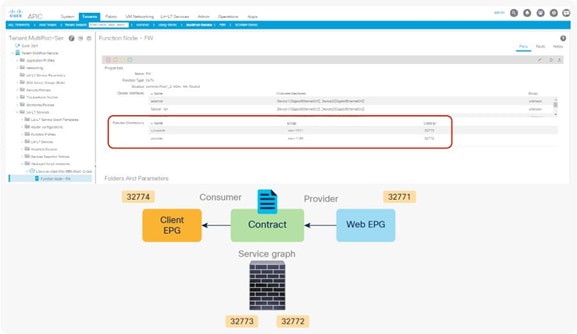
Class ID for service node
When you add the service graph, the permit rule is updated as shown in Table 2. Because the intention of the service graph is to insert service devices between the consumer and provider EPGs, the consumer and provider connectors for the service node are inserted between the consumer and provider EPGs.
Table 2. Permit rule with service graph (without PBR)
| Source class ID |
Destination class ID |
Filter ID |
Action |
| 32774 |
32773 |
The filter used in |
Permit |
| 32772 |
32771 |
default |
Permit |
| 32771 |
32772 |
The reverse filter of the filter |
Permit |
| 32773 |
32774 |
The reverse filter of the filter |
Permit |
When you add the service graph with PBR, the redirect policy is programmed on the switches on which the consumer or provider EPG is located. In this example, PBR destination 172.16.1.1 is the consumer connector of the firewall node, and 172.16.2.1 is the provider connector the firewall node. If the source class is 32774 (Client EPG) and the destination class is 32771 (Web EPG), traffic will be redirected to the consumer connector the PBR node. Then traffic is routed by the PBR node and returns to the Cisco ACI fabric. Here the source class is 32772 (provider connector of the PBR node), and the destination class is 32771, which is permitted. Return traffic is also redirected to the provider connector of the PBR node because the source class is 32771 and the destination class is 32774. After PBR for return traffic is performed and traffic returns to the Cisco ACI fabric from the PBR node, the source class is 32773 (consumer connector of PBR node), and the destination class is 32774, which is permitted (Figure 13 and Table 3).
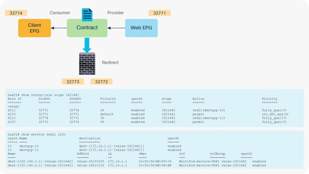
After service graph with PBR is deployed
Table 3. Permit and redirect rules with service graph (with PBR)
| Source EPG |
Destination EPG |
Filter ID |
Action |
| 32774 |
32771 (Web EPG) |
38 (The filter used in the contract subject) |
Redirect |
| 32772 |
32771 (Web EPG) |
Default |
Permit |
| 32771 |
32774 (Client EPG) |
39 (The reverse filter of the filter |
Redirect |
| 32773 |
32774 (Client EPG) |
39 (The reverse filter of the filter |
Permit |
Note: The filter ID in the show zoning-rule output in Figure 13 shows that the default filter (permit all) is applied in a rule for the PBR node provider connector to the provider EPG (Table 3). This same behavior applies to a regular service graph without PBR (Table 2). Cisco ACI uses the default filter for zoning rules that don’t include a consumer EPG class ID as a source or destination, even with a specific filter used in the contract subject for which you applied a service graph. The assumption is that security enforcement has already been performed on the external (consumer) side. Starting from APIC Release 4.2(3), the filters-from-contract option is available at a service graph template level to use the specific filter of the contract subject instead of the default filter (Table 4). See the “Filters-from-contract option” section for details.
Table 4. Permit and redirect rules with service graph (with PBR and the filters-from-contract option)
| Source EPG |
Destination EPG |
Filter ID |
Action |
| 32774 |
32771 (Web EPG) |
38 (The filter used in the contract subject) |
Redirect |
| 32772 |
32771 (Web EPG) |
38 (The filter used in the contract subject) |
Permit |
| 32771 |
32774 (Client EPG) |
39 (The reverse filter of the filter |
Redirect |
| 32773 |
32774 (Client EPG) |
39 (The reverse filter of the filter |
Permit |
If you deploy a service graph with PBR with the default configuration, the keepalive messages from L4-L7 devices to servers to monitor their availability is failed. It is because there is no permit entry for the traffic from the provider EPG to the provider connector of the PBR node. In the preceding example, traffic from the consumer EPG (32774) to the consumer connector of the PBR node (32773) and from the provider EPG (32771) to the provider connector of the PBR node (32772) is not permitted. For situations in which you require permit entries for this traffic, you can set the Direct Connect option to True.
This configuration is located in Tenant > L4-L7 Services > L4-L7 Service Graph Templates > Policy (Figure 14). The default setting is False.
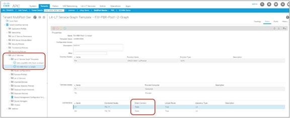
Direct Connect option in L4-L7 service graph template
Figure 15 shows an example in which Direct Connect is set to True on both connections. In this case, traffic from the consumer EPG (32774) to the consumer side of the PBR node (32773) and from the provider EPG (32771) to the provider side of the PBR node (32772) are permitted (Table 5).
After service graph with PBR is deployed (Direct Connect set to True)
Table 5. Permit and redirect rules with service graph (with PBR and Direct Connect set to True)
| Source class ID |
Destination class ID |
Filter ID |
Action |
| 32774 (Client EPG) |
32771 (Web EPG) |
38 (The filter used in the contract subject) |
Redirect |
| 32772 (provider connector of service node) |
32771 (Web EPG) |
default |
Permit |
| 32771 (Web EPG) |
32774 (Client EPG) |
39 (The reverse filter of the filter used in the contract subject) |
Redirect |
| 32773 (consumer connector of service node) |
32774 (Client EPG) |
39 (The reverse filter of the filter used in the contract subject) |
Permit |
| 32774 (Client EPG) |
32773 (consumer connector of service node) |
38 (The filter used in the contract subject) |
Permit |
| 32771 (Web EPG) |
32772 (provider connector of service node) |
default |
Permit |
Service EPG selector for endpoint security groups (ESGs)
Prior to the 5.2(4) release, users could not manually create a contract with a service EPG created through service graph, which would have some challenges. For example:
● Direct Connect can be used to add a permit rule for the traffic from the service EPG to the consumer/provider EPG. However, an EPG that is not either the consumer or provider EPG cannot communicate with the service EPG unless a vzAny contract or a preferred group is configured.
● As vzAny includes the service EPG, a vzAny-to-vzAny contract can permit traffic between the service EPG and other EPGs in the VRF. However, all other EPGs in the VRF can talk to the service EPG instead of allowing specific EPGs to communicate with the service EPG.
The figure below illustrates the second example.
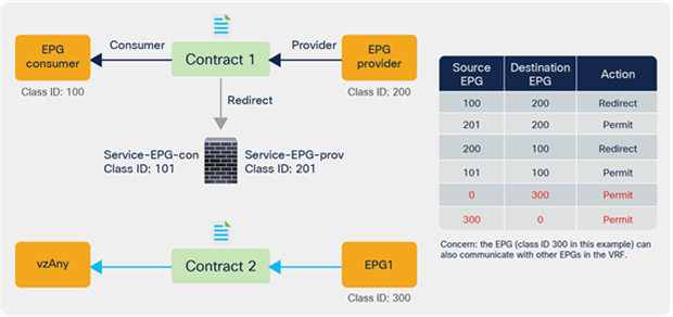
Use case example without service EPG selector for ESGs
Starting from APIC Release 5.2(4), Service EPG selector for ESGs allows users to map a service EPG to an ESG and create a contract with the ESG. The figure below illustrates a use case. In addition to a vzAny-to-vzAny permit contract, adding a deny contract between the service ESG and other ESGs to allow specific ESGs to communicate with the service ESG.
The figure below illustrates an example. Service EPG “Service-EPG-con” for the firewall consumer connector is mapped to ESG “Service-ESG-con” that has a contract with ESG1 and/or an L3Out EPG. Zoning-rules that involve service EPGs are inherited when the service EPG class ID gets changed to the ESG class ID. It’s important to note that the ESG for the service device interface (Service-ESG-con in this example) can have a contract with an ESG or an L3Out EPG, not an EPG because contracts between an EPG and an ESG are not supported.
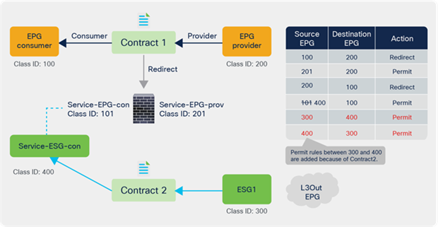
Use case example 1 with service EPG selector for ESGs
The figure below illustrates another use case. A vzAny-to-vzAny contract is used to permit all traffic within the VRF. By adding a deny contract between vzAny to the ESG for the service-device interface (Service-ESG-con in this example), only specific EPGs can communicate with the service-device interface.
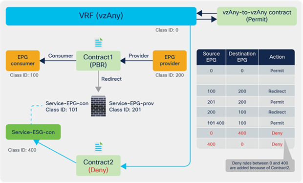
Use case example 2 with service EPG selector for ESGs
This configuration is located in Tenant > Endpoint Security Groups > ESG_NAME > Selectors > Service EPG Selectors. The list of LifCtx (service-device connector, representing the service EPG) defined in device selection policies in the tenant shows up in the dropdown menu. By selecting a LifCtx, the service EPG is mapped to the ESG.
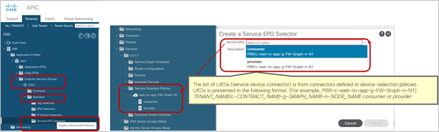
Service EPG selector for ESGs
Service EPG selector for ESGs has the following considerations:
● Contracts between an EPG and an ESG are not supported.
● Although zoning-rules that involve service EPGs are inherited, the class ID of the service EPG will be changed to a global class ID because it is mapped to an ESG that uses a global class ID. Because the class ID gets changed, traffic loss will occur.
● All the LifCtx in the same device using the same BD should be mapped to the same ESG. For example:
◦ One-arm mode PBR. (Please see the example in Figure 20 below.)
◦ Reuse the service device interface for multiple service graph deployments.
● The Service EPG and the ESG must be in the same VRF.
◦ If the service EPG and ESG are in different tenants, there are additional considerations. (Please see the example in figures 21 and 22 below.)
● Multi-Site is not supported. (NDO does not support ESG as of this writing.)
● Support only for L3 PBR with PBR destination in a BD.
◦ PBR destination in an L3Out is not supported. (Contracts can be manually configured with an L3Out EPG.)
◦ L1/L2 PBR is not supported. (L1/L2 device interfaces are not supposed to communicate with servers directly.)
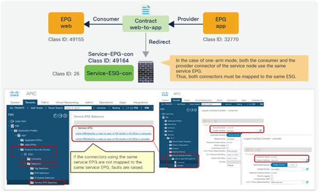
All the LifCtx in the same device using the same BD should be mapped to the same ESG (one-arm mode)
Figures 21 and 22 below illustrate a consideration if the service EPG and the ESG are in different tenants. It’s important to note that a service EPG object is internally created in the tenant where the L4-L7 device is defined. If an L4-L7 device is defined in a different tenant, the service EPG object is internally created in the tenant where the L4-L7 device resides. If the service EPG to an ESG mapping is defined only in one tenant, as illustrated in Figure 21, it is supported.
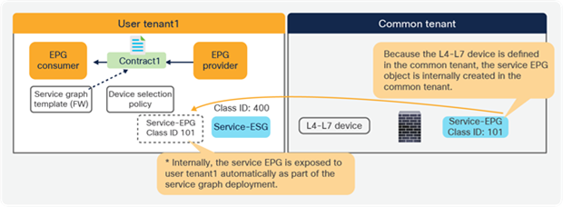
Multiple tenants consideration (supported)
However, if the service EPG to an ESG mapping is defined in multiple tenants, as illustrated in Figure 22, it is NOT supported because it could cause conflict.
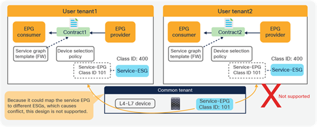
Multiple tenants consideration (not supported)
Multiple consumer and provider EPGs
Service graphs are applied to contracts, and contracts can be placed between multiple pairs of EPGs. When you use service graphs with L4-L7 devices in routed (Go-To) mode or bridge (Go-Through) mode, the reuse of a graph must take into account the bridge domain to which the L4-L7 device is attached. When you use a service graph with PBR, you have more flexibility in attaching the contract between any two pairs of EPGs across multiple bridge domains, as long as this approach is compatible with the VRF instance to which the L4-L7 device belongs.
If you have two consumer EPGs and two provider EPGs, as in the previous example, policy is programmed as shown in Figure 23. If traffic is between one of the consumer EPGs and one of the provider EPGs, it is redirected to the PBR node.
After service graph with PBR is deployed (multiple consumer and provider EPGs)
This section explains PBR end-to-end packet flow using a PBR destination in an L3 bridge domain. For a PBR destination in an L3Out, refer to the section, “PBR destination in an L3Out”. Note that because several designs and traffic flows are possible, the example used in this discussion may not exactly reflect your environment.
Figure 24 shows an example in which the Client EPG is a consumer EPG, and the Web EPG is a provider EPG with a contract with the PBR service graph, and the client endpoint generates traffic destined for the web endpoint. If Leaf1 hasn’t learned the destination endpoint, Leaf1 can’t resolve the destination EPG class ID. Therefore, the traffic goes to the spine proxy, and the spine node forwards the traffic to Leaf3, to which the destination endpoint is connected. Leaf3 learns the source endpoint from this traffic. Then Leaf3 can resolve the source and destination EPG class IDs, so PBR is performed on Leaf3. Here, the destination segment ID (VNID) is rewritten to the bridge domain VNID of the PBR node bridge domain, and the destination MAC address is rewritten to the PBR node MAC address that is configured in the APIC. Leaf3 doesn’t know where the destination MAC address is connected, the traffic goes to the spine proxy, and the spine node forwards the traffic to Leaf2, to which the PBR node is connected. Leaf2 doesn’t learn the client IP address from this traffic because Endpoint Dataplane Learning is disabled for the PBR node bridge domain.
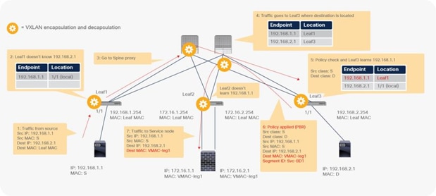
End-to-end packet flow example (client to web)
Traffic is routed on the PBR node based on the routing table of the PBR node, and traffic returns to the Cisco ACI fabric. Because Leaf2 does not know the destination endpoint, the traffic goes to the spine proxy again and then to Leaf3. Here the source EPG is the PBR node provider connector class ID, and the destination is the provider EPG class ID. The traffic is only permitted and arrives at the web endpoint. The key point here is that Leaf3 does not learn the client IP address from this traffic because Endpoint Dataplane Learning is disabled for the PBR node bridge domain (Figure 25).
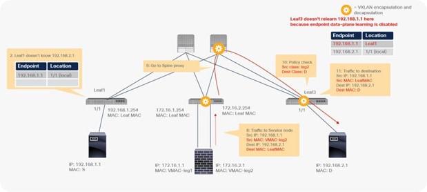
End-to-end packet flow example (PBR node to web)
For the return traffic, because Leaf3 can resolve both the source and destination EPG class IDs, PBR is performed on Leaf3. The destination MAC address is rewritten, and the traffic goes to the PBR node on the provider side (Figure 26).
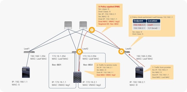
End-to-end packet flow example (web to client)
The traffic returns to the Cisco ACI fabric from the consumer side of the PBR node. Because Leaf2 does not know the destination endpoint, the traffic goes to the spine proxy again and then to Leaf1. Leaf1 performs policy enforcement, and the traffic is permitted because the source EPG is the PBR node consumer connector class ID, and the destination is the consumer EPG class ID. Leaf1 does not learn the web endpoint IP address from this traffic because Endpoint Dataplane Learning for the PBR node bridge domain is disabled (Figure 27).
End-to-end packet flow example (PBR node to client)
The rest of the traffic will also be redirected on Leaf3 because Leaf1 does not learn the web endpoint IP address in this example. Cisco ACI enforces policies depending on whether the source and destination class IDs can be determined, which depends on the traffic flow. If traffic is generated from the web endpoint first, or if other traffic lets Leaf1 learn the web endpoint IP address, PBR policy can be performed on Leaf1.
As it is routed at a leaf, TTL is decreased. If you run a traceroute, ACI leaf IP would be in your traceroute output. Because a network device sends an ICMP "Time Exceeded" message back to the source by using its closest IP as the source IP, you may see the same subnet range twice, depending on your network design.
For example, if ICMP traffic is redirected and you run a traceroute from an external client behind L3Out to the destination endpoint at 192.168.2.1 (Figure 28), you would see the following hops in traceroute output:
1. IP of L3Out interface on either Leaf1 or Leaf2 (192.168.1.251 or 192.168.1.252)
2. IP of external connector of PBR node (172.16.1.1) if PBR node decreases TTL*
3. IP of L3Out interface on Leaf2 (192.168.1.252)
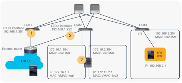
Traceroute consideration (topology)
This is because the Leaf2 uses its L3Out interface IP as source IP for the ICMP “Time Exceeded” message back to the external client. Figure 29 illustrates the logical network topology.
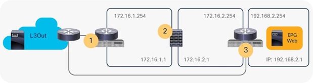
Traceroute consideration (logical network topology)
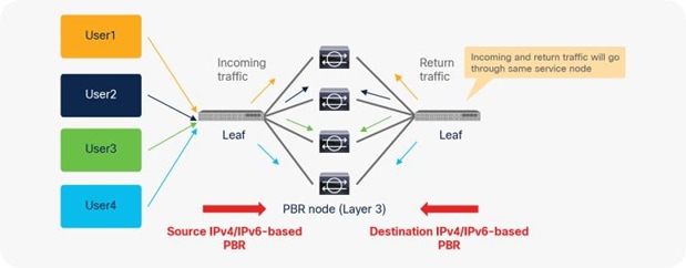
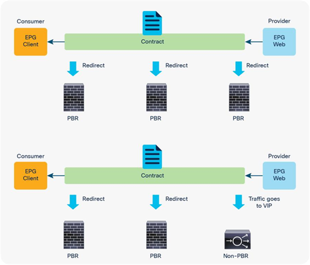
So far, this document has discussed PBR based on the assumption that the PBR destination is a single L4-L7 device. However, PBR can load-balance traffic to more than just one PBR destination such as an individual firewall. If, for example, you have three PBR destinations, IP and MAC address pairs are configured in a PBR policy, and traffic is redirected to one of the three PBR nodes based on hashing. The hash tuple is the source IP address, destination IP address, and protocol number by default. Because L4-L7 devices perform connection tracking, they must see both directions of a flow. Therefore, you need to make sure that incoming and return traffic are redirected to the same PBR node. Symmetric PBR is the feature that enables this capability (Figure 30).
Symmetric PBR is useful for inserting multiple service nodes to scale a system. It requires Cisco Nexus 9300-EX and -FX platform leaf switches onward.
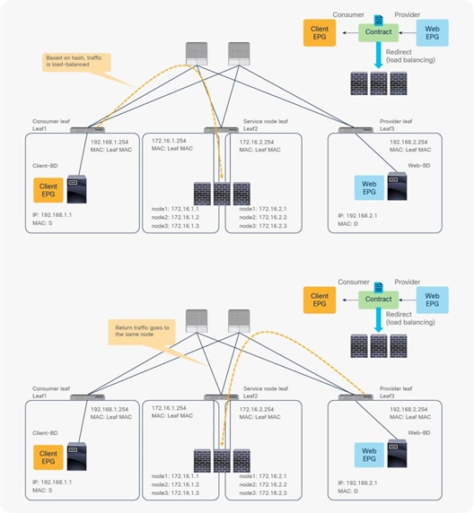
Symmetric PBR
Starting from APIC Release 2.2(3j) and 3.1, the hash tuple is user configurable. You can use the source IP address only; the destination IP address only; or a combination of the source IP address, destination IP address, and protocol number (default). If you use the source IP address only or the destination IP address only option, you need to configure options for both directions to keep traffic symmetric. For example, if you use the source IP address only option for incoming traffic, you must use the destination IP address only option for return traffic to keep traffic symmetric, as shown in Figure 31.
The use case for symmetric PBR with the source IP only or the destination IP only is a scenario in which the traffic from a source IP address (user) always needs to go through the same service node.
Example with only source IP address and destination IP address
This section describes various deployment options you can use with PBR.
EPGs in a different subnet in the same VRF instance
The basic, common deployment of PBR consists of EPGs and PBR nodes in the same VRF instance, with each EPG in a different bridge domain, as shown in Figure 32 and Figure 33. The gateway for the endpoints is the Cisco ACI fabric, which is required for PBR.
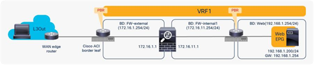
Intra-VRF design (L3Out EPG to Web EPG)
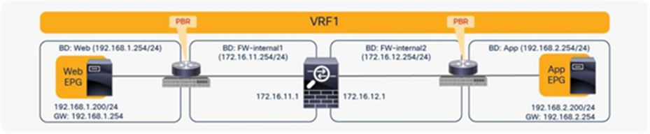
Intra-VRF design (Web EPG to App EPG)
Consumer and provider EPGs in the same subnet
PBR can redirect traffic even if the endpoints are in the same bridge domain.
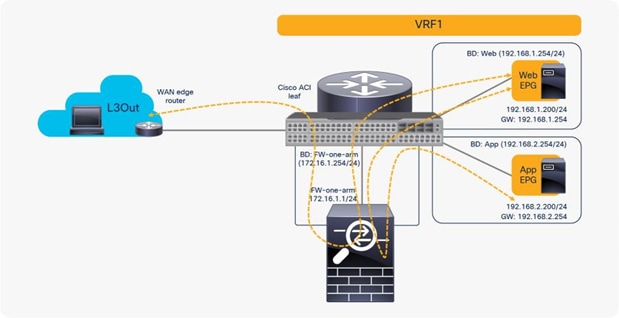
For example, even though the Web and App EPGs are in the same bridge domain and the same subnet, PBR can be enforced. This design requires the use of the same interface on the PBR node unless the PBR node has a more specific static route. Such a scenario is called a one-arm mode deployment (Figure 34). Though this example uses a dedicated bridge domain for the PBR node, L3 PBR destination can be in the same bridge domain and the same subnet with Web and App EPGs after APIC Release 3.1.
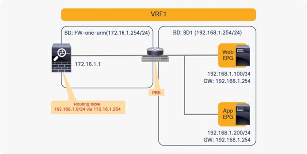
Consumer and provider EPGs in the same subnet
Note: The firewall may prevent traffic from entering and leaving through the same interface. Therefore, the firewall must be configured appropriately to permit intra-interface traffic. See the Cisco Adaptive Security Appliance (ASA) configuration example later in this document.
Prior to APIC Release 4.0, you cannot associate a service graph with an intra-EPG contract. For releases later than APIC Release 4.0, PBR with an intra-EPG contract is supported. Starting with APIC Release 5.2, PBR with an intra Ext-EPG contract is also supported.
PBR can be deployed as bidirectional PBR or unidirectional PBR.
Unidirectional PBR for load balancer without source NAT
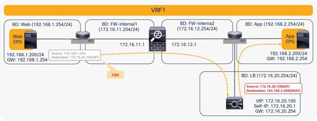
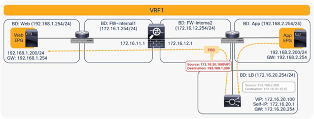
One use case for unidirectional PBR is load-balancer integration without source Network Address Translation (NAT).
For example, as shown in Figure 35, because the destination IP address from the client is the virtual IP address on the load balancer, PBR is not required for client-to-web traffic. If the load balancer doesn’t translate the source IP address, PBR is required for return traffic; otherwise, the return traffic won’t come back to the load balancer.
Unidirectional PBR example
Note: You must set Direct Connect to True to allow keepalive messages from the load-balancer endpoint to the web endpoint.
Unidirectional PBR with the other connector in L3Out
Prior to APIC Release 4.1.2, both consumer and provider connectors of a PBR node had to be in a bridge domain and not in an L3Out; even with unidirectional PBR. Starting from APIC Release 4.1.2, this is no longer required. A L3Out can be used to connect the interface of L4-L7 device whereas the other interface is connected to a bridge domain and it receives traffic via PBR redirection.
One use case for unidirectional PBR with the other connector in L3Out is a NAT IP-pool outside the local subnet. Figure 36 illustrates an example. Consumer-to-provider traffic is redirected to one of the PBR nodes. The PBR node performs source NAT, and the NAT IP addresses are outside of the local subnet. Thus, L3Out is required to add the route to the NAT IP addresses that are the destination IP addresses of the return traffic from the provider. PBR is not required on the provider connector of the PBR node because the return traffic is destined to the NAT IP address.
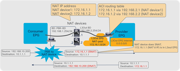
Design example of unidirectional PBR with the provider connector in a L3Out
Prior to APIC Release 5.0, L3Out was supported only on the provider connector (the provider side interface of a L4-L7 device) of the last node in a service graph that is exemplified in Figure 36.
Starting from APIC Release 5.0, this requirement is no longer mandatory. Figure 37 illustrates an example of unidirectional PBR for the provider to consumer direction with the other connector in L3Out. The use case is a load balancer VIP outside the local subnet. Consumer to provider traffic is going to the VIP through L3Out, which doesn’t require PBR because it’s destined to the VIP. If the load balancer doesn’t perform NAT, PBR is required for return traffic. In this example, the L3Out is used on consumer connector.
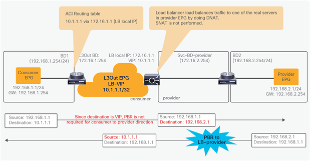
Design example of unidirectional PBR for provider to consumer direction with the consumer connector in a L3Out
Note: You need to make sure that IP translation is performed properly on the PBR node, and make sure that the specific L3Out EPG subnet is configured if there are other L3Out EPGs in the same VRF. Otherwise, a loop could occur, because L3Out EPG classification is per VRF, not per interface.
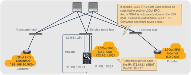
Design consideration for unidirectional PBR with the other connector
Starting with APIC Release 5.2, PBR destinations can be in an L3Out instead of an L3 bridge domain. Refer to the section, “PBR destination in an L3Out” for details.
PBR across VRF instances
PBR can be deployed between EPGs in different VRF instances. One use case for this design is a service in one VRF instance shared by endpoints in different VRF instances.
A PBR device can be between consumer and provider VRF instances or in either instance, as shown in Figure 39. The PBR node bridge domain must be in either the consumer or provider EPG VRF instance. It must not be in another VRF instance.
Inter-VRF design
Note: Consumer and provider VRF instances can be in the same tenant or in different tenants.
In the case of an inter-VRF contract, provider and consumer routes are leaked between VRF instances, and the consumer VRF instance enforces the Cisco ACI contract policy. Similarly, with PBR, route leaking across VRF instances is required even with PBR. (A route-leaking configuration example is presented later in this document.) For example, VRF1 must contain provider EPG subnet 192.168.2.0/24 that is leaked from VRF2, and VRF2 must contain consumer EPG subnet 192.168.1.0/24 that is leaked from VRF1. After the service graph is deployed, the consumer VRF instance (scope 2949121) has permit and redirect rules for inter-VRF traffic, and the provider VRF instance (scope 2326532) has a permit rule for intra-VRF traffic (Figure 40 and Table 6).
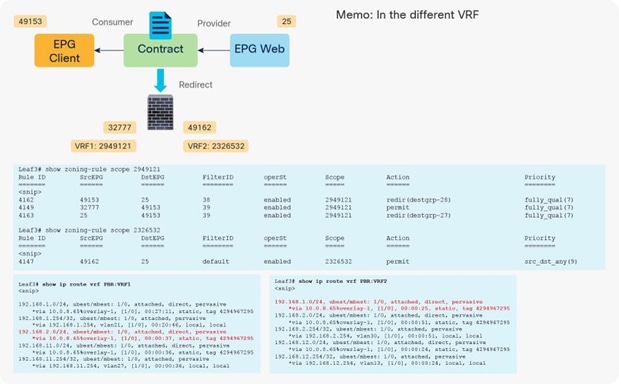
Inter-VRF design with permit and redirect rules
Table 6. Permit and redirect rules (inter-VRF instance)
| VRF instance |
Source class ID |
Destination class ID |
Filter ID |
Action |
| VRF1 |
49153 (Client EPG) |
25 (Web EPG) |
38 (The filter used in the contract subject) |
Redirect |
| VRF1 |
32777 (consumer connector of service node) |
49153 (Client EPG) |
39 (The reverse filter of the filter used in the contract subject) |
Permit |
| VRF1 |
25 (Web EPG) |
49153 (Client EPG) |
39 (The reverse filter of the filter used in the contract subject) |
Redirect |
| VRF2 |
49162 (provider connector of service node) |
25 (Web EPG) |
default |
Permit |
Two-node service graph (firewall with PBR plus load balancer with NAT)
If you want to insert two service nodes, for example, a firewall followed by a load balancer, between EPGs, you will likely need PBR to insert the firewall because the traffic is destined for the load balancer’s virtual IP address, which doesn’t require redirection.
For example, the first node is the firewall, which is a PBR node, and the second node is the load balancer, which is not a PBR node. The consumer endpoint generates traffic destined for the virtual IP address of the load balancer. The traffic will be redirected to the firewall, where PBR policy is applied on the traffic from the Web EPG (the provider EPG) to the load-balancer EPG (the consumer connector of the second node). Then the traffic will go to the load balancer, and the source and destination IP addresses are translated by the load balancer. Finally, it will go to the destination (Figure 41).
Two-node service graph (incoming traffic)
For return traffic, because source NAT was performed by the load balancer, the destination IP address is the load balancer’s IP address. Traffic goes back to the load balancer, and the IP addresses will be translated. Then PBR policy is applied again between the load-balancer EPG (the consumer side of the second node) and the Web EPG (Figure 42).
Prior to APIC Release 3.2, either the first or the second node in a service graph can be a PBR node. Therefore, NAT is required on the second node in this example.
Two-node service graph (return traffic)
Note: If you use Cisco Nexus 9300 platform switches (except Cisco Nexus 9300-EX and -FX platform switches onward), the first node (the PBR node) must be under a different leaf node than the leaf node to which the consumer endpoint and the second node are connected. However, the consumer endpoint, the provider endpoint, and the second node can be under the same leaf node. If the second node is a PBR node, the PBR node must be under a different leaf node than the leaf node to which the provider side of the first node and the provider EPG are connected, but the consumer endpoint and the PBR node can be under the same leaf node.
Cisco Nexus 9300-EX and -FX platform leaf switches onward do not have this requirement (Figure 43).
Cisco Nexus 9300 platform (except Cisco Nexus 9300-EX and -FX platforms onward) leaf node considerations
Multinode service graph with PBR
Multinode PBR is introduced in APIC Release 3.2. It enables you to use PBR multiple times in a service graph, which simplifies insertion of multiple service functions in a specific order without VRF or BD sandwich considerations.
PBR node and non-PBR node can be mixed in same service graph, for example:
● FW (PBR) + IPS (PBR) + TCP optimizer (PBR)
● FW (PBR) + IPS (PBR) + Load Balancer (non-PBR)
Multinode PBR examples
Multinode PBR without non-PBR node
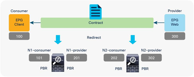
Figure 45 and Table 7 illustrate an example of what policies are programmed for two-node PBR. If all of the service nodes are PBR nodes, it will perform similarly to single-node PBR. The destination class ID is always the consumer or provider EPG class ID.
● Traffic from Client EPG (class ID: 100) to Web EPG (class ID: 300) is redirected to the consumer connector of N1.
● Traffic from provider connector N1 (class ID: 201) to Web EPG (class ID: 300) is redirected to the consumer connector of N2.
● Traffic from provider connector N2 (class ID: 302) to Web EPG (class ID: 300) is permitted.
● Traffic from Web EPG (class id: 300) to Client EPG (class ID: 100) is redirected to the provider connector of N2.
● Traffic from consumer connector N2 (class ID: 202) to EPG Client (class ID: 100) is redirected to the provider connector of N1.
● Traffic from consumer connector N1 (class ID: 101) to EPG Client (class ID: 100) is permitted.
Two-node PBR
Table 7. Permit and redirect rules (Two node PBR)
| Source class ID |
Destination class ID |
Filter ID |
Action |
| 100 (Client EPG) |
300 (Web EPG) |
The filter used in the contract subject |
Redirect to N1-consumer |
| 201 (provider connector of N1) |
300 (Web EPG) |
default |
Redirect to N2-consumer |
| 302 (provider connector of N2) |
300 (Web EPG) |
default |
Permit |
| 300 (Web EPG) |
100 (Client EPG) |
The reverse filter of the filter used in the contract subject |
Redirect to N2-provider |
| 202 (consumer connector of N2) |
100 (Client EPG) |
The reverse filter of the filter used in the contract subject |
Redirect to N1-provider |
| 101 (consumer connector of N1) |
100 (Client EPG) |
The reverse filter of the filter used in the contract subject |
Permit |
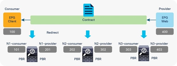
Figure 46 and Table 8 illustrate an example of what policies are programmed for three-node PBR. Similar to the two-node PBR case, the source and destination class ID is always the consumer or provider EPG class ID.
Three-node PBR
Table 8. Permit and redirect rules (three-node PBR)
| Source class ID |
Destination class ID |
Filter ID |
Action |
| 100 (Client EPG) |
400 (Web EPG) |
The filter used in the contract subject |
Redirect to N1-consumer |
| 201 (provider connector of N1) |
400 (Web EPG) |
Default |
Redirect to N2-consumer |
| 302 (provider connector of N2) |
400 (Web EPG) |
Default |
Redirect to N3-consumer |
| 403 (provider connector of N3) |
400 (Web EPG) |
Default |
Permit |
| 400 (Web EPG) |
100 (Client EPG) |
The reverse filter of the filter used in the contract subject |
Redirect to N3-provider |
| 303 (consumer connector of N3) |
100 (Client EPG) |
The reverse filter of the filter used in the contract subject |
Redirect to N2-provider |
| 202 (consumer connector of N2) |
100 (Client EPG) |
The reverse filter of the filter used in the contract subject |
Redirect to N1-provider |
| 101 (consumer connector of N1) |
100 (Client EPG) |
The reverse filter of the filter used in the contract subject |
Permit |
Multinode PBR with a combination of PBR and non-PBR nodes
If you have both PBR and non-PBR nodes in a service graph, what policies should be programmed differ from those presented in Tables 7 or 8 because non-PBR nodes (for example, Load Balancer VIP, firewall with NAT, etc.) do not require redirection as traffic is destined to them. When PBR is required, it is important to identify whether or not a connector of a service node is a traffic destination. For a combination of PBR and non-PBR nodes, a new flag has been introduced called an “L3 Destination (VIP),” on the Device Selection Policy, to identify where the traffic is destined in the service chain.
Figure 47 and Table 9 illustrate an example of what policies should be programmed for a three-node service graph where N1 and N2 are PBR nodes; for example, firewall and IPS without address translation, and N3 is Load Balancer with source NAT.
Since traffic from Client EPG is destined to Load Balancer VIP, the destination class ID is the consumer connector of N3 where the VIP is located, until the traffic goes through N3.
● Traffic from Client EPG (class ID: 100) to the consumer connector of N3 (class ID: 303) is redirected to the consumer connector of N1.
● Traffic from the provider connector of N1 (class id: 201) to the consumer connector of N3 (class ID: 303) is redirected to the consumer connector of N2.
● Traffic from the provider connector of N2 (class ID: 302) to the consumer connector of N3 (class ID: 303) is permitted.
● Traffic from the provider connector of N3 (class ID: 403) to Web EPG (class ID: 400) is permitted.
For return traffic, the destination class ID is the provider connector of N3 where the Source NAT’d address is located until the traffic goes through N3. The traffic from the Web EPG (class ID: 400) to the provider connector of N3 is permitted, and then the traffic will be redirected to the provider connector of N2 and then to provider connector of N1, similar to the Client-to-Web traffic flow.
Combination of PBR and non-PBR nodes (Node 3 is Load Balancer with Source NAT.)
Table 9. Permit and redirect rules (combination of PBR and non-PBR nodes)
| Source class ID |
Destination class ID |
Filter ID |
Action |
| 100 (Client EPG) |
303 (consumer connector of N3. VIP on LB) |
The filter used in the contract subject |
Redirect to N1-consumer |
| 201 (provider connector of N1) |
303 (consumer connector of N3. VIP on LB) |
default |
Redirect to N2-consumer |
| 302 (provider connector of N2) |
303 (consumer connector of N3. VIP on LB) |
default |
Permit |
| 403 (provider connector of N3) |
400 (Web EPG) |
default |
Permit |
| 400 (Web EPG) |
403 (provider connector of N3. SNAT address) |
default |
Permit |
| 303 (consumer connector of N3) |
100 (Client EPG) |
The reverse filter of the filter used in the contract subject |
Redirect to N2-provider |
| 202 (consumer connector of N2) |
100 (Client EPG) |
The reverse filter of the filter used in the contract subject |
Redirect to N1-provider |
| 101 (consumer connector of N1) |
100 (Client EPG) |
The reverse filter of the filter used in the contract subject |
Permit |
In this example, the consumer and provider connector of N3 must be set to the new flag “L3 Destination (VIP)” on the Device Selection Policy, so that the PBR policy is programmed accordingly.
The filter-from-contract option in the service graph template is introduced in APIC Release 4.2(3). It enables you to use the specific filter of the contract subject where the service graph is attached, instead of the default filter for zoning rules that don’t include the consumer EPG class ID as a source or destination. (This option is disabled by default. Refer to the “Dataplane programming” section for the default behavior.)
Figure 48, Table 10, and Table 11 show a use case example. One node and two node service graphs are attached to contracts with different filters between the same consumer and provider EPGs pair. Contract1, with a one-node service graph, uses permit-https filter and Contract2, with a two-node service graph, uses permit-http filter. The first service node interfaces used in both service graphs are same. With the default behavior using the default filter for zoning rules that don’t include a consumer EPG class ID as a source or destination, the result will be a duplicated zoning rule. The zoning rule generated by those two service graphs will have a rule with the same exact source class, destination class, and filter (default filter), however with a different redirect destination, even though the filters in the contracts are different. Hence, use of the filter-from-contract option is required for this use case to enforce different policies.
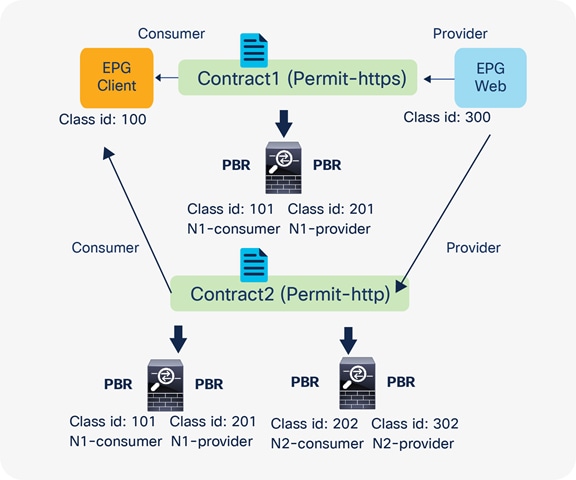
Two-node PBR and three-node PBR using the same service node
Note: If the source or destination class ID is unique, the filters-from-contract option is not mandatory. For example, Contract1 and Contract2 have different provider EPGs or the provider connector of the first service node is different.
Table 10. Permit and redirect rules for the one-node PBR (without the filters-from-contract option)
| Source class ID |
Destination class ID |
Filter ID |
Action |
| 100 (Client EPG) |
300 (Web EPG) |
The filter used in the contract subject (source port: any; destination port: 443) |
Redirect to N1-consumer |
| 201 (provider connector of N1) |
300 (Web EPG) |
Default |
Permit |
| 300 (Web EPG) |
100 (Client EPG) |
The reverse filter of the filter used in the contract subject (source port: 443; destination port: any) |
Redirect to N1-provider |
| 101 (consumer connector of N1) |
100 (Client EPG) |
The reverse filter of the filter used in the contract subject (source port: 443; destination port: any) |
Permit |
Table 11. Permit and redirect rules for the two-node PBR (without the filters-from-contract option)
| Source class ID |
Destination class ID |
Filter ID |
Action |
| 100 (Client EPG) |
300 (Web EPG) |
The filter used in the contract subject (source port: any; destination port: 80) |
Redirect to N1-consumer |
| 201 (provider connector of N1) |
300 (Web EPG) |
Default |
Redirect to N2-consumer |
| 302 (provider connector of N2) |
300 (Web EPG) |
Default |
Permit |
| 300 (Web EPG) |
100 (Client EPG) |
The reverse filter of the filter used in the contract subject (source port: 80; destination port: any) |
Redirect to N2-provider |
| 202 (consumer connector of N2) |
100 (Client EPG) |
The reverse filter of the filter used in the contract subject (source port: 80; destination port: any) |
Redirect to N1-provider |
| 101 (consumer connector of N1) |
100 (Client EPG) |
The reverse filter of the filter used in the contract subject (source port: 80; destination port: any) |
Permit |
By enabling the filters-from-contract option at either or both service graph templates, zoning rules become unique and different policies can be enforced. Tables 12 and 13 show the zoning-rule examples with the filters-from-contract option enabled at both service graph templates.
Table 12. Permit and redirect rules for the one-node PBR (with the filters-from-contract option)
| Source class ID |
Destination class ID |
Filter ID |
Action |
| 100 (Client EPG) |
300 (Web EPG) |
The filter used in the contract subject (source port: any; destination port: 443) |
Redirect to N1-consumer |
| 201 (provider connector of N1) |
300 (Web EPG) |
The filter used in the contract subject (source port: any; destination port: 443) |
Permit |
| 300 (Web EPG) |
100 (Client EPG) |
The reverse filter of the filter used in the contract subject (source port: 443; destination port: any) |
Redirect to N1-provider |
| 101 (consumer connector of N1) |
100 (Client EPG) |
The reverse filter of the filter used in the contract subject (source port: 443; destination port: any) |
Permit |
Table 13. Permit and redirect rules for the two-node PBR (with the filters-from-contract option)
| Source class ID |
Destination class ID |
Filter ID |
Action |
| 100 (Client EPG) |
300 (Web EPG) |
The filter used in the contract subject (source port: any; destination port: 80) |
Redirect to N1-consumer |
| 201 (provider connector of N1) |
300 (Web EPG) |
The filter used in the contract subject (source port: any; destination port: 80) |
Redirect to N2-consumer |
| 302 (provider connector of N2) |
300 (Web EPG) |
The filter used in the contract subject (source port: any; destination port: 80) |
Permit |
| 300 (Web EPG) |
100 (Client EPG) |
The reverse filter of the filter used in the contract subject (source port: 80; destination port: any) |
Redirect to N2-provider |
| 202 (consumer connector of N2) |
100 (Client EPG) |
The reverse filter of the filter used in the contract subject (source port: 80; destination port: any) |
Redirect to N1-provider |
| 101 (consumer connector of N1) |
100 (Client EPG) |
The reverse filter of the filter used in the contract subject (source port: 80; destination port: any) |
Permit |
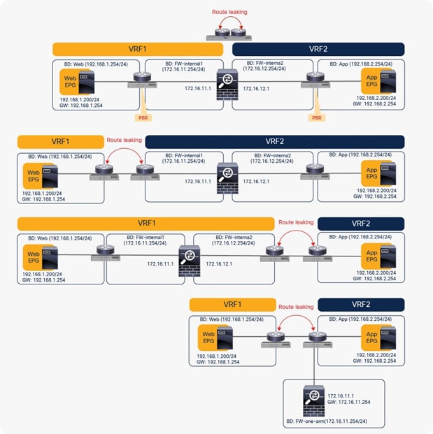
Reuse of service graph with PBR
The service graph template and L4-L7 device can be reused in multiple contracts. For example, if you want to insert a firewall in multiple inter-EPG traffic flows in a tenant, you probably want to use the same firewall with either the same or different interfaces. Both designs are possible.
Reuse the same PBR node with different interfaces
You can reuse the same PBR node with a different interface for each tier. From the L3Out EPG to the web EPG, traffic is redirected to FW-external, and return traffic is redirected to FW-internal1. From the web EPG to the App EPG, traffic is redirected to FW-internal1, and return traffic is redirected to FW-internal2 (Figure 49).
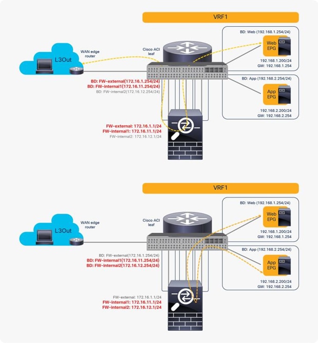
Reuse the same PBR node (using different interfaces)
In this case, you can reuse the service graph template and the L4-L7 device. To redirect traffic to a different interface based on the source and destination EPG pair, a different PBR policy and a device selection policy are required. (For basic information about the service graph configuration with PBR, see the later part of this document.)
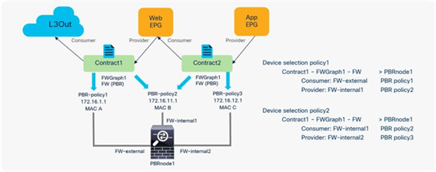
Here is a configuration example (Figure 50):
● Contract (Tenant > Security Policies > Contracts)
◦ Contract1: Between L3Out EPG and Web EPG
◦ Contract2: Between Web EPG and App EPG
● L4-L7 device (Tenant > L4-L7 Services > L4-L7 Devices)
◦ PBRnode1 has three cluster interfaces
◦ FW-external: Security zone for L3Out connection
◦ FW-internal1: Security zone for Web EPG
◦ FW-internal2: Security zone for AppEPG
● Service graph template (Tenant > L4-L7 Services > L4-L7 Service Graph Templates)
◦ FWGraph1: Node1 is the firewall function node that is PBR enabled
● PBR policies (Tenant > Networking > Protocol Policies > L4-L7 Policy Based Redirect)
◦ PBR-policy1 (172.16.1.1 with MAC A)
◦ PBR-policy2 (172.16.11.1 with MAC B)
◦ PBR-policy3 (172.16.12.1 with MAC C)
● Device selection policy (Tenant > L4-L7 Services > Device Selection Policies)
◦ Contract1-FWGraph1-FW (If FWGraph1 is applied to Contract1, the firewall function node will be this node.)
◦ Node: PBRnode1
◦ Consumer: FW-external with PBR-policy1
◦ Provider: FW-internal1 with PBR-policy2
◦ Contract2-FWGraph1-FW (If FWGraph1 is applied to Contract2, the firewall function node will be this node.)
◦ Node: PBRnode1
◦ Consumer: FW-internal1 with PBR-policy2
◦ Provider: FW-internal2 with PBR-policy3
Configuration example: Reuse the same PBR node (using different interfaces)
Reuse the same PBR node and the same interface
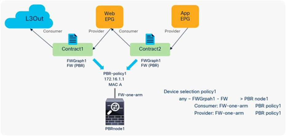
If you want to use the same PBR node and its interfaces, you can reuse the service graph template, L4-L7 device, PBR policy, and device selection policy. In this example, traffic is redirected to FW-one-arm if it is between the L3Out EPG and the Web EPG, or between the Web EPG and the App EPG (Figure 51).
Reuse the same PBR node (using the same interfaces in one-arm mode)
Here is a configuration example (Figure 52):
● Contract (Tenant > Security Policies > Contracts)
◦ Contract1: Between L3Out EPG and Web EPG
◦ Contract2: Between Web EPG and App EPG
● L4-L7 device (Tenant > L4-L7 Services > L4-L7 Devices)
◦ PBRnode1 has one cluster interface
◦ FW-one-arm
● Service graph template (Tenant > L4-L7 Services > L4-L7 Service Graph Templates)
◦ FWGraph1: Node1 is the firewall function node that is PBR enabled
● PBR policies (Tenant > Networking > Protocol Policies > L4-L7 Policy Based Redirect)
◦ PBR-policy1 (172.16.1.1 with MAC A)
● Device selection policy (Tenant > L4-L7 Services > Device Selection Policies)
◦ any-FWGraph1-FW (If FWGraph1 is applied to any contract, the firewall function node will be this node.)
◦ Node: PBRnode1
◦ Consumer: FW-one-arm with PBR-policy1
◦ Provider: FW-one-arm with PBR-policy1
Configuration example: Reuse the same PBR node (using the same interface)
You may wonder whether you can use a firewall with two interfaces rather than use one-arm mode or a different interface for each EPG. For example, you may want consumer-to-provider traffic to always be redirected to the FW-external interface, and you may want provider-to-consumer traffic to always be redirected to the FW-internal interface, regardless of which EPG is a consumer or a provider (Figure 53).
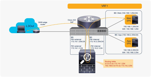
Reuse the same PBR node (using two-arm mode for north-south traffic)
The problem with such a design is the routing configuration on the firewall. The firewall probably has a 0.0.0.0/0 route through 172.16.1.254 in the FW-external bridge domain and a 192.168.1.0/24 route through 172.16.2.254 in the FW-internal bridge domain, which is fine for the traffic between the L3Out EPG and the Web EPG. However, for the traffic between the Web and - App EPGs, the firewall would have 192.168.2.0/24 routed through 172.16.2.254 in the FW-internal bridge domain. If traffic from the App EPG is destined for the Web EPG is redirected to FW-internal, the firewall will send it back using 172.16.2.254 as the next hop because both 192.168.1.0/24 and 192.168.2.0/24 use 172.16.2.254 as the next hop. The result is a traffic path like that of a one-arm design with intra-interface traffic forwarding. Therefore, you can use a two-arm design for north-south traffic, but you should use a one-arm design for the east-west traffic because of the routing table on the PBR node (Figure 54).
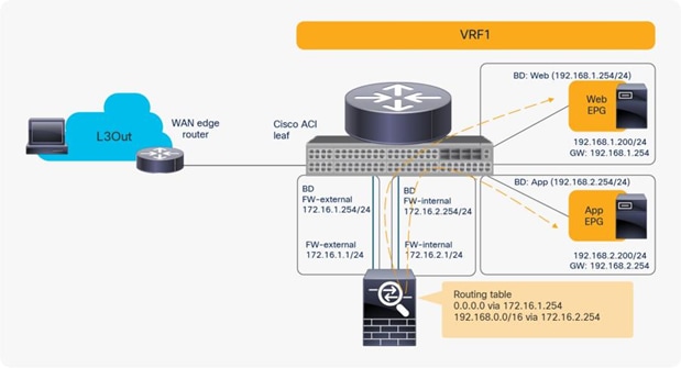
Reuse the same PBR node (using one-arm mode for east-west traffic)
The vzAny managed object is a collection of all EPGs in a VRF instance. It is useful if you have a security requirement that is applied to all EPGs in a VRF; it also helps to reduce policy TCAM consumption.
Prior to APIC Release 3.2, although you cannot associate a service graph with PBR with a contract with vzAny as provider, you can associate it with vzAny as consumer. This is helpful for inserting service nodes for traffic between shared service providers and all EPGs as consumer in a VRF. Figure 55 illustrates an example of this. If you have a contract with PBR between vzAny as consumer and an NFS (network file system) EPG as provider in VRF1, the NFS access from all endpoints in VRF1 to NFS can be inspected by firewall without consuming policy TCAM for multiple consumer EPGs.
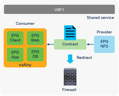
vzAny as consumer (shared service-provider use case)
For releases later than APIC Release 3.2, PBR with a contract with vzAny as provider is also supported. This is helpful for inserting service nodes everywhere, all EPGs to all EPGs, in a VRF. Figure 56 illustrates an example of this. If you have vzAny as consumer and also provider for a contract with PBR, all of the traffic between endpoints within the VRF can be inspected by firewall.
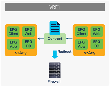
vzAny as consumer and provider (all EPGs to all EPGs use case)
Note: You should use a one-arm design for an “all EPGs to all EPGs” use case because the rule for consumer-to-provider traffic is the same as the rule for provider-to-consumer traffic. Both are vzAny to vzAny, which means we cannot use a different action. (See Figure 57.)
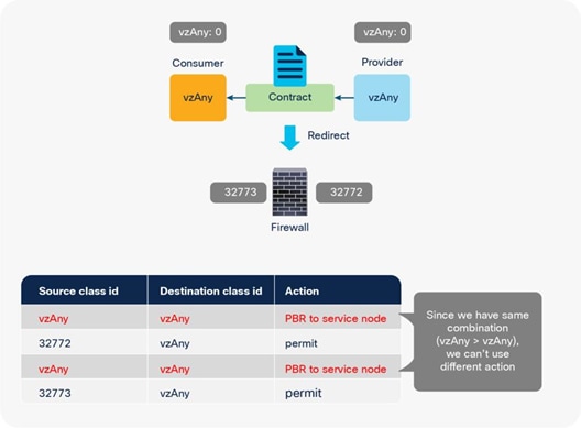
Why only one-arm mode works for an “all EPGs to all EPGs” use case
The traffic coming back from a service node to the ACI fabric is not redirected even though we have PBR rules for all EPGs to all EPGs, because the precise filter rule takes precedence. For example, after vzAny to vzAny traffic is redirected to a service node, the traffic comes back to the ACI fabric. Here the source class ID is 32773 (PBR node) and destination class ID 0 (vzAny), which is a more precise rule than vzAny to vzAny; thus, traffic is permitted instead of redirected (Table 14).
Table 14. Permit and redirect rules (an “all EPGs to all EPGs” use case with one-arm)
| Source class ID |
Destination class ID |
Filter ID |
Action |
| 0 (vzAny) |
0 (vzAny) |
The filter used in the contract subject |
Redirect to service node |
| 32773 (interface of service node) |
0 (vzAny) |
default |
Permit |
| 0 (vzAny) |
0 (vzAny) |
The reverse filter of the filter used in the contract subject |
Redirect to service node |
| 32773 (interface of service node) |
0 (vzAny) |
The reverse filter of the filter used in the contract subject |
Permit |
An intra-EPG contract is a contract that is applied to endpoints in the same EPG. It is useful if you need security enforcement even within an EPG.
Prior to APIC Release 4.0, you cannot associate a service graph with an intra-EPG contract. For releases later than APIC Release 4.0, PBR with an intra-EPG contract is supported. This is helpful for inserting service nodes for traffic between endpoints in the same EPG. Figure 58 illustrates an example of this.
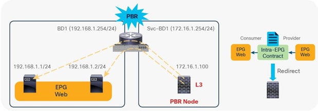
PBR with intra-EPG contract example
The main considerations for Cisco ACI PBR with intra-EPG contract are as follows:
● You should use a one-arm design.
● Intra-EPG contract with Service Graph without PBR or Copy is not possible because there is no way to insert service node between endpoints in the same BD without PBR.
● Main use case is for security-device insertion; for example, firewall, IPS, and so on. A load-balancer use case is out of scope.
Starting with APIC Release 5.2, it's possible to configure PBR with an intra Ext-EPG contract for the L3Out EPG (External EPG). Here are some key points to be aware of regarding the use of PBR with an intra Ext-EPG contract:
● You cannot use an intra Ext-EPG contract with an L3Out EPG with 0.0.0.0/0 or 0::0. The APIC raises a fault if an intra Ext-EPG contract is configured on such an L3Out EPG. The workaround is to use 0.0.0.0/1 and 128.0.0.0/1 for the L3Out EPG to catch all subnets. This is because the L3Out EPG with a 0.0.0.0/0 or 0::0 subnet has a dual pcTag behavior. See the ACI Contract Guide for details about the L3Out EPG with 0.0.0.0/0 subnet.
● Unlike intra-EPG contracts on an EPG, an implicit deny rule is not automatically added in the case of intra Ext-EPG contracts on an L3Out EPG. Intra Ext-EPG isolation needs to be enabled to deny other traffic.
Before a service graph with PBR is applied to an intra-EPG contract between the Client EPGs (class ID 49155), permit and implicit deny entries between them are programmed on leaf nodes (Figure 59 and Table 15). If the traffic between endpoints in the Client EPG matches the filter in the contract, the traffic is permitted because intra-EPG permit rules have higher priority than the implicit deny rule.
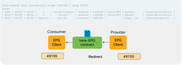
Intra-EPG contract zoning-rule example (without PBR)
Table 15. Permit and deny rules without PBR
| Source class ID |
Destination class ID |
Filter ID |
Action |
| 49155 (Client EPG) |
49155 (Client EPG) |
9 (The filter used in the contract subject) |
Permit |
| 49155 (Client EPG) |
49155 (Client EPG) |
8 (The reverse filter of the filter used in the contract subject) |
Permit |
| 49155 (Client EPG) |
49155 (Client EPG) |
Default (implicit) |
Deny |
Note: The implicit deny rule is not automatically added in the case of an intra Ext-EPG contract on an L3Out EPG. Intra Ext-EPG isolation needs to be enabled to deny other traffic between the EPG.
When the service graph is deployed, the class ID for the service node is created and the permit rules are updated (see Figure 60 and Table 16).
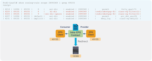
Intra-EPG contract zoning-rule example (with PBR)
Table 16. Permit rule with PBR
| Source class ID |
Destination class ID |
Filter ID |
Action |
| 49155 (Client EPG) |
49155 (Client EPG) |
9 (The filter used in the contract subject) |
Redirect to service node |
| 16386 (connector of service node) |
49155 (Client EPG) |
default |
Permit |
| 49155 (Client EPG) |
49155 (Client EPG) |
8 (The reverse filter of the filter used in the contract subject) |
Redirect to service node |
| 16386 (connector of service node) |
49155 (Client EPG) |
8 (The reverse filter of the filter used in the contract subject) |
Permit |
| 49155 (Client EPG) |
49155 (Client EPG) |
Default (implicit) |
Deny |
Note: You should use a one-arm design for PBR with intra-EPG and intra Ext-EPG contract because the rule for consumer-to-provider traffic is the same as the rule for provider-to-consumer traffic, which is the same as the “vzAny to vzAny” use case in a previous section.
This section discusses several optional features: PBR node tracking, location-based PBR for Cisco ACI Multi-Pod designs, and designs with the PBR node and consumer and provider EPGs in the same subnet.
PBR node tracking was introduced in APIC Release 2.2(3j) and Release 3.1. It enables you to prevent redirection of traffic to a PBR node that is down. If a PBR node is down, the PBR hashing can begin selecting an available PBR node in a policy. This feature requires Cisco Nexus 9300-EX or -FX platform leaf switches onward.
Figure 61 shows how PBR node tracking works. The service leaf node to which the PBR node is connected periodically sends keepalive by using Internet Control Message Protocol (ICMP), Transmission Control Protocol (TCP), or L2Ping or HTTP to the local PBR node and then periodically announces availability information to all the other leaf switches through a system-wide broadcast message. This information allows all the leaf nodes to know whether they can still use that specific PBR node when applying the PBR policy locally. Starting from APIC Release 5.2(1), this periodical announcement is used to announce PBR destination MACs for the feature: L3 PBR without MAC configuration (dynamic PBR destination MAC detection).
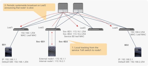
Tracking behavior
The following tracking types are supported:
● TCP for L3 PBR, starting from APIC Release 2.2(3j)
● ICMP for L3 PBR, starting from APIC Release 3.1
● L2Ping for L1/L2 PBR starting from APIC Release 4.1
● HTTP for L3 PBR, starting from APIC Release 5.2
What if only the consumer or the provider connector of the PBR node is down? To prevent traffic from being black-holed, Cisco ACI must avoid use of the PBR node for traffic in both directions. Some L4-L7 devices can bring down an interface if another interface is down. You can use this capability on the L4-L7 device to avoid black-holing. If the PBR node doesn’t have this capability, you should use the health group feature to disable PBR for the node if either the consumer or provider connector is down.
Each PBR destination IP and MAC address can be in a health group. For example, assume that you have two PBR node destinations. One has 172.16.1.1 as the consumer connector and 172.16.2.1 as the provider connector, and these are in Health-group1. The other has 172.16.1.2 as the consumer connector and 172.16.2.2 as the provider connector, and these are in Health-group2. If either of the PBR destinations in the same health group is down, that node will not be used for PBR (Figure 62).
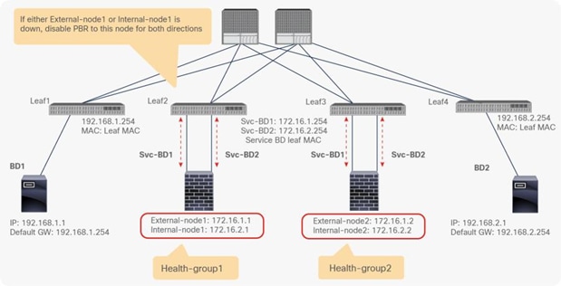
Health group feature
Threshold
You must make sure that an L4-L7 device is not a bottleneck, and that you have a sufficient number of available L4-L7 devices to handle the traffic. To determine whether PBR should or should not be enabled, PBR tracking offers configurable minimum and maximum threshold values based on the percentage of available PBR destinations in a PBR policy. If the number of available PBR destinations falls below the minimum percentage, the traffic is permitted or dropped rather than redirected, based on the down action permit, deny, and bypass configuration, which is explained in the next section. For the traffic to be redirected again, the number of available PBR destinations must reach the maximum percentage.
For example, assume that you have five PBR destinations with the threshold feature enabled, with 20 percent set as the minimum percentage and 80 percent set as the maximum percentage. Assume that all the PBR destinations are up initially, and that traffic is load-balanced across PBR nodes 1 through 5. If nodes 1 through 4 are down, PBR is disabled because the percentage is lower than or equal 20 percent. Even if node 4 comes up again (that is, nodes 4 and 5 are up), PBR still is disabled because the percentage is still lower than 80 percent. If node 2 through 5 are up, PBR is enabled again because the percentage is 80 percent (Figure 63).
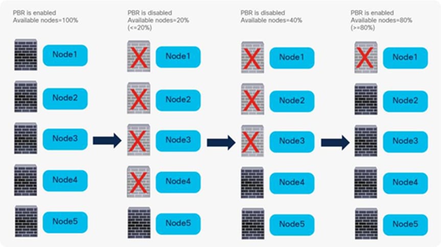
Threshold feature
PBR node tracking offers a configurable behavior for the case in which the number of available PBR destinations in the PBR policy falls below the minimum percentage set as the threshold, as explained in the previous section. This configurable behavior is called down action. Available down action options are listed in Table 17.
Table 17. Down action options
| Down action |
Cisco ACI release when first introduced |
Behavior |
Use case |
| Permit (default) |
2.2(3j) |
Traffic directly goes to destination without PBR. |
Skip over optional service node in 1 node service graph. |
| Deny |
3.1 |
Traffic is dropped. |
Mandate service insertion. |
| Bypass |
4.1.2 |
Traffic is redirected to next PBR node in the service graph. |
Skip over optional service node in Multi nodes service graph. |
The design considerations of down action are as follows:
● Tracking and threshold must be enabled to use down action.
● Use the same down action on both the provider and consumer connectors of a given PBR node. If you don’t configure the down action this way, APIC raises a fault under the tenant when deploying the service graph.
The default down action is Permit, which means that traffic will be permitted between endpoints. The use cases for down action Permit include scenarios in which PBR is used for a traffic optimizer or an optional service node that can be skipped rather than having traffic dropped (Figure 64).
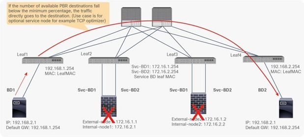
Down action Permit
If you set the down action to Deny, traffic will be dropped between endpoints. Some use cases for down action Deny are PBR for a firewall, IPS, or security service node that must be included (Figure 65).
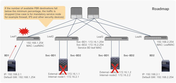
Down action Deny
Starting from APIC Release 4.1.2, Bypass action is introduced, which is for a multi-node PBR service graph with an optional service node that can be bypassed. Figure 66 illustrates an example, using a 2-node service graph that has a first function node and a second function node. Each function node can have one or more PBR destinations in a PBR policy. If the number of available PBR destinations in the PBR policy for the first function node falls below the minimum percentage, the traffic is redirected to one of the available PBR destinations in the PBR policy for the second function node as a backup path, instead of having traffic dropped or permitted directly to the destination.
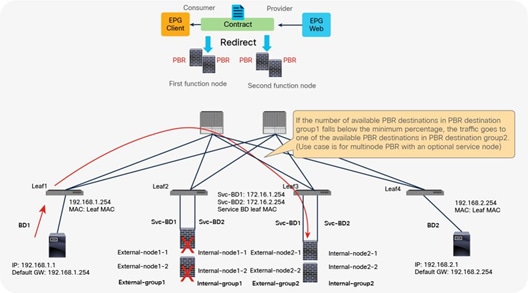
Down action Bypass
If the number of available PBR destinations in the PBR policy for the second function node also falls below the minimum percentage, the traffic also bypasses the second function node, which means that traffic is permitted directly to the destination.
The design considerations of Bypass action are as follows:
● The Bypass feature is not required for a 1-node service graph.
● The Bypass feature is not supported with L1/L2 PBR prior to APIC Release 5.0.
● A service node that does NAT cannot be bypassed because it breaks the traffic flow.
● As of APIC Release 5.0, the use of Bypass in conjunction with the following features is not supported:
◦ Remote leaf
◦ One-arm mode L4-L7 devices (Bypass works only with L4-L7 devices that are in two-arm mode.)
◦ If you use the same PBR policy in more than one service graph and the Bypass action is enabled, you should use a unique “PBR policy name” that has same PBR destination configuration. If you use the same PBR policy with Bypass enabled that is used in more than one service graph, APIC rejects the configuration (CSCvp29837). The reason is that the backup for the Bypass action is set per PBR policy, and, if you have different service graphs using the same PBR policy with Bypass enabled, the backup for the Bypass might be different for each service graph (see figures 67 and 68).
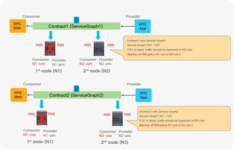
Design consideration: PBR destination is used in more than 1 service graphs and bypass action is enabled
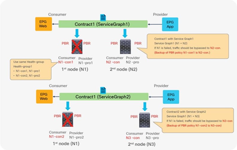
Workaround: use unique PBR policy name using same PBR destination IP and MAC
Note: Use the same health-group for those PBR policies because the PBR destination IP and MAC addresses are the same.
If one of the PBR nodes in a PBR policy is down, and PBR is still enabled, traffic will be rehashed by using the available PBR nodes in the PBR policy by default. Some traffic that has been going through the available PBR nodes could be load-balanced to different PBR nodes and could be affected, even though they haven’t been going through the failed PBR node, because a new PBR node that receives the traffic does not have existing connection information (Figure 69).
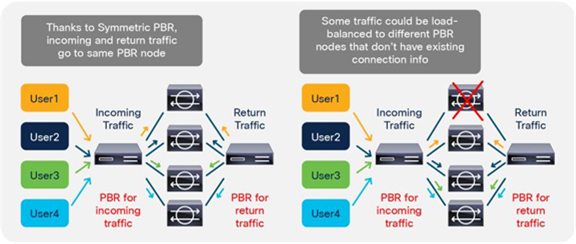
PBR node failure behavior (Default: Resilient Hashing is disabled.)
With Resilient hash PBR (introduced in APIC Release 3.2), only the traffic that went through a failed node will be redirected to a different available PBR node. Other traffic will still be redirected to the same node, so that the traffic going through other PBR nodes will not be impacted (see Figure 70).
Resilient hash can be set on L4-L7 Policy Based Redirect policy.
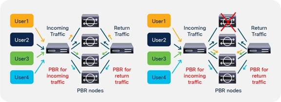
PBR node failure behavior (Resilient Hashing is enabled.)
Note: The traffic that went through the failed node will be redirected to one of the available PBR nodes, not redistributed to multiple available PBR nodes. This is a tradeoff between resiliency and load-balancing distribution. If the capacity of PBR node during PBR node failure is a concern, you can use backup PBR node to take care of the traffic that went through the failed node. Please see the Backup PBR policy (N+M high availability) section for details.
Note: If there are multiple failures, the traffic going through the available nodes could have been rehashed, depending on the situation. For example, if Node A goes down, and Node B goes down, and then Node D goes down (as shown in Figure 71), traffic 3, 5, and 6, which are hashed to C, E, or F, are, luckily, not impacted.
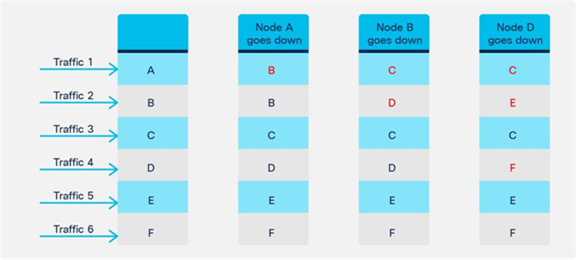
Multiple failure scenario (Node A down, Node B down and then Node D down)
If Node F goes down, and Node E goes down, and then Node A goes down (as shown in Figure 72), the traffic that is going through available nodes could be impacted.
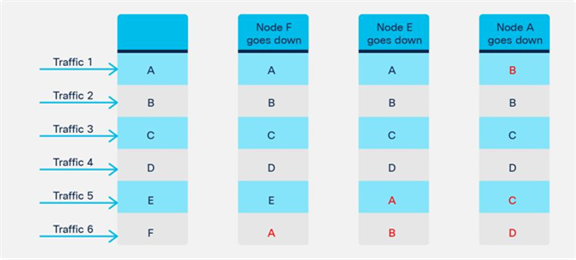
Multiple failure scenario (Node F down, Node E down, and then Node A down)
Backup PBR policy (N+M high availability)
With Resilient Hash, because all of the traffic that went through a failed node will be redirected to one of the available nodes, the capacity of the node could be a concern. The node could double the amount of traffic compared with when all of the PBR nodes are available. Starting from Cisco ACI Release 4.2, Backup PBR policy is introduced. It enables you to set backup PBR destinations. Instead of using one of the available primary PBR nodes, the traffic that went through a failed node will be redirected to a backup PBR node; other traffic will still be redirected to the same PBR node (see Figure 73). In this way, you can avoid concerns about capacity overload.
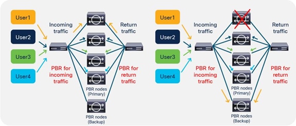
PBR node failure behavior (Backup PBR destination)
The design considerations of Backup PBR policy are as follows:
● Resilient Hash must be enabled.
● Prior to APIC Release 4.2, Backup PBR policy is supported for L3 PBR only, not L1/L2 PBR, because L1/L2 PBR doesn’t support multiple active PBR destinations in a PBR policy as of APIC Release 4.2. After APIC Release 5.0, Backup PBR policy is supported for L1/L2 PBR.
● A primary PBR destination and its backup PBR destination must be classified to the same hidden service EPG. It means concrete interfaces for both primary and backup PBR destinations need to be part of the same cluster interface. It also means the primary and backup PBR destinations must be defined under the same L4-L7 device.
● A PBR destination can be used as a primary PBR destination in a PBR policy or a backup PBR destination in a backup PBR policy of the PBR policy, not both. It means a primary PBR destination can’t be used as a backup PBR destination in its backup PBR policy. (A primary PBR destination can be used as a backup PBR destination in different PBR policies if the primary and backup destinations are in the same bridge domain).
● One backup PBR policy can be used by only one PBR policy. If not, the configuration will be rejected. If you want to use the same backup PBR destination for multiple PBR policies, you should create two different backup PBR policies using the same backup PBR destination and the same health-group (Figure 74).
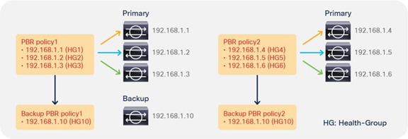
Use the same backup PBR destination for multiple PBR policies
● Multiple backup PBR destinations can be set in a backup PBR policy. Thus, not only N+1 high availability, but also N+M high availability designs are possible. When you have multiple available backup PBR destinations, one of the available backup PBR destinations is used in the order of the IP addresses by default, from the lowest to the highest (Figure 75). If all of your backup PBR destinations are used, traffic is redirected to one of the available primary and backup PBR destinations in the order of primary IP addresses, from the lowest to the highest (Figure 76). Starting from APIC Release 4.2(5) and 5.0, Destination Name based sorting can be used instead of IP address based sorting. For more information about Destination Name option, please refer to the Destination Name based sorting section.
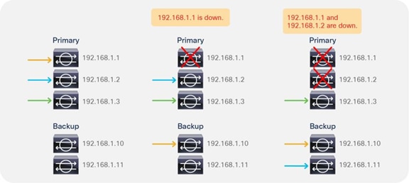
Multiple backup PBR nodes scenario
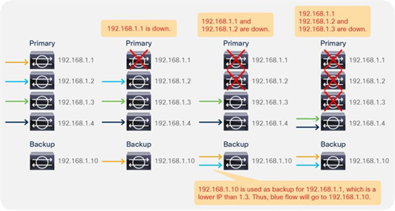
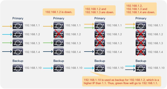
Multiple-failure scenario where the number of failure nodes is bigger than the number of backup PBR nodes
● If you have backup PBR destinations, a threshold value is calculated based on the number of used primary and backup PBR destinations divided by the number of configured primary PBR destinations (Figure 70).
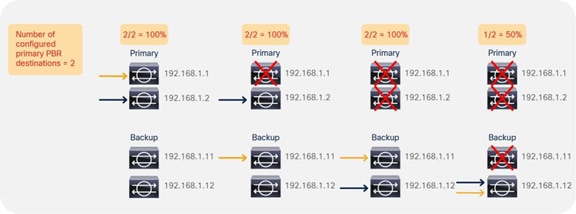
Threshold calculation example
● Backup PBR policy is supported with Multi-Pod. With location-aware PBR, if a local primary PBR destination is down, a local backup PBR destination is used. If all of the local primary and backup PBR destinations are down, a remote primary PBR destination is used. If the remote primary PBR destination is also down, the remote backup PBR destination is used (Figure 78).
● Backup PBR policy within a site is supported, because it is the site local configuration. Use of primary or backup PBR destinations in different sites is not supported.
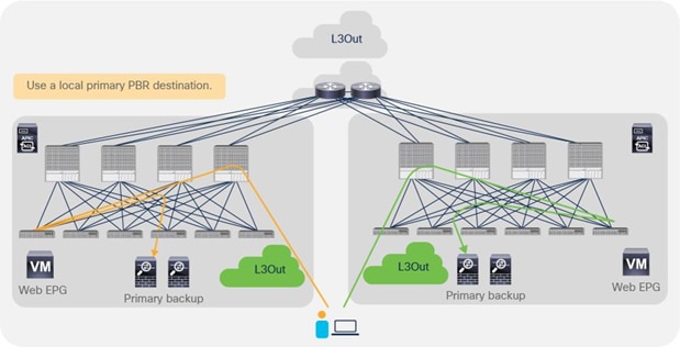
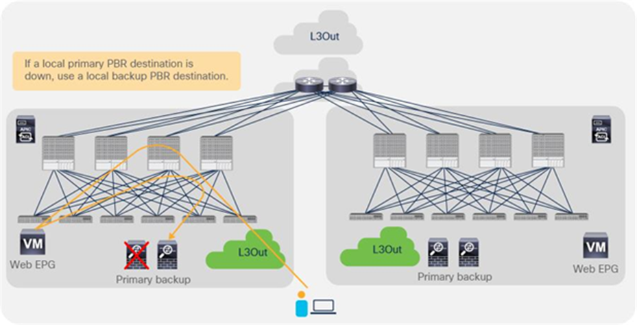
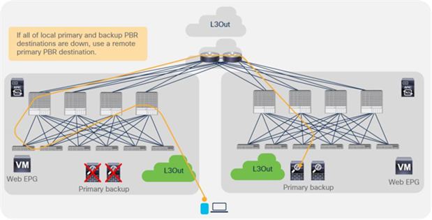
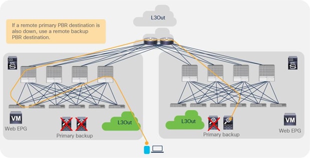
Backup PBR policy with a Multi-Pod example
Note: The same with the examples in Figures 64 and 65 without backup PBR policy; if there are multiple failures, the traffic going through the available nodes could have been rehashed, depending on the situation. Figure 79 illustrates an example if we have Node A to F as primary and Node Y to Z as backup.
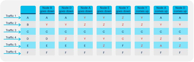
Example of a multiple-failure scenario
Location-based PBR for Cisco ACI Multi-Pod design
Starting from Cisco ACI Release 2.0, Cisco ACI offers a solution, Cisco ACI Multi-Pod, that allows you to interconnect different Cisco ACI leaf-and-spine fabrics under the control of the same APIC cluster. This design provides an operationally simple way to interconnect Cisco ACI fabrics that may be either physically co-located or geographically dispersed.
This section focuses on the PBR deployment option for a Cisco ACI Multi-Pod design. However, several deployment models are available for integrating L4-L7 network services into a Cisco ACI Multi-Pod fabric. For more information about Cisco ACI Multi-Pod fabric, https://www.cisco.com/c/en/us/solutions/collateral/data-center-virtualization/application-centric-infrastructure/white-paper-c11-739971.html
As described in the previous section, PBR redirection is based on hashing. It does not use location awareness. For example, even though the source and destination endpoints and an available PBR node are in the same pod, traffic can be redirected to an available PBR node in a different pod. In this case, traffic would go to the different pod and then come back, which increases latency and consumes interpod network resources.
Figure 80 shows an example in which the endpoints and PBR nodes are in different pods. The destination is 192.168.1.202 in Pod2. Traffic from the external network is received on the border leaf nodes in Pod1 and is sent through the spine to the destination leaf on which the destination endpoint is located. The PBR policy is then applied on the destination leaf and, based on hashing, the PBR node in Pod1 is selected. Traffic must finally come back from the PBR node in Pod1 to reach the destination endpoint in Pod2. The end result is that, for this ingress flow, the traffic must hair-pin three times across the IPN.
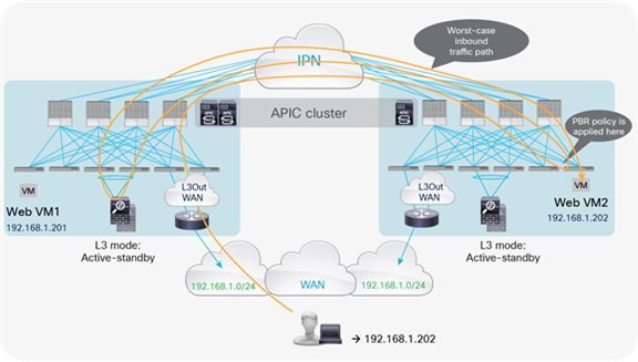
Worst traffic path example
The suboptimal traffic behavior shown in the previous figure can be avoided by combining the use of host route advertisement from the Cisco ACI border leaf nodes (available from Cisco ACI Release 4.0 onward) with a functionality that is named “location-based PBR” (available from Cisco ACI Release 3.1 onward). With location-based PBR, traffic hair-pinning across pods can be avoided because the destination leaf node in which the endpoint is located preferably selects the local service node. Location-based PBR requires Cisco Nexus 9300-EX and -FX platform leaf switches onward.
Figure 81 shows an example in which the destination is 192.168.1.201 in Pod1. Because of the host route advertisement function provided by the ACI border leaf nodes, traffic originating from an external client can be selectively steered toward Pod1 and reach the destination leaf node in which the 192.168.1.201 endpoint is located. The destination leaf node in Pod1 then selects the local PBR node, which sends the traffic back toward the destination. Similar behavior is achieved for traffic destined for the endpoint 192.168.1.202 in Pod2.
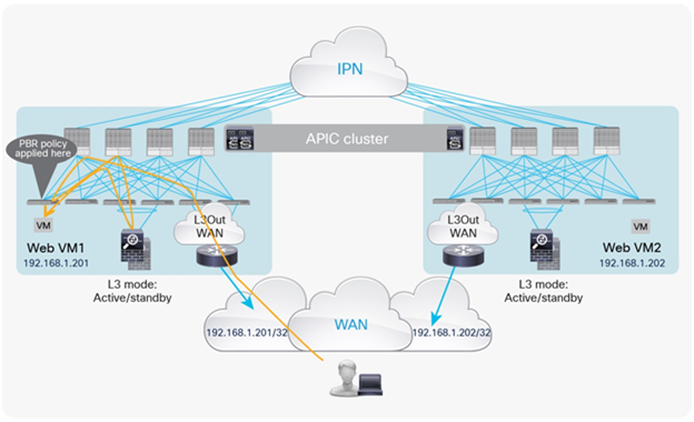
Location-based PBR with host route advertisement (inbound)
For return traffic, the destination leaf node applies the PBR policy and selects the same local PBR node. Then traffic goes back to the external network domain via the L3Out connection defined on the local border leaf nodes, which is the default behavior with Cisco ACI Multi-Pod (Figure 82).
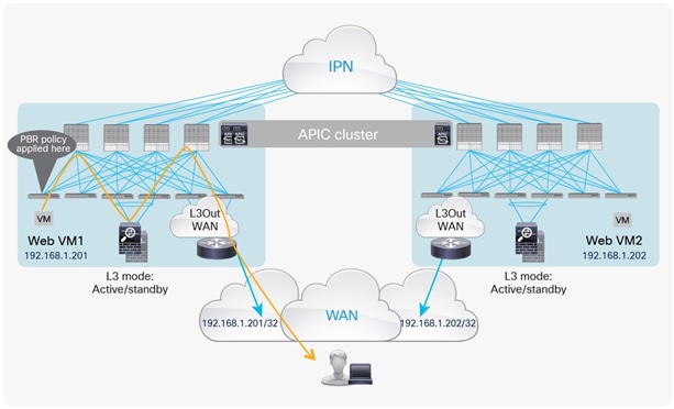
Location-based PBR with host-route advertisement (outbound)
When the Cisco ACI leaf nodes in Pod1 detect the failure of the local service node, the hashing function starts selecting a service node located in a remote pod. This process causes traffic hair-pinning across the IPN, but it prevents traffic from becoming black-holed.
Note: Since the connection state is not synced between the independent pairs of firewalls deployed across pods, long-lived traffic flows originally flowing through the failed firewall in Pod1 will have to be re-established by way of the firewall in the remote pod.
Design with PBR node and consumer and provider EPGs in the same subnet
Prior to APIC Release 3.1, the PBR node bridge domain had to be different than the consumer and provider bridge domains. Therefore, a different bridge domain and subnet range were required for the PBR node. Starting from APIC Release 3.1, this requirement is no longer mandatory, and the PBR bridge domain can be the same as the consumer or provider bridge domain (Figure 83). This feature requires Cisco Nexus 9300-EX and -FX platform leaf switches onward.
Note: As of APIC Release 3.1, you do not have to disable data-plane learning in the PBR node bridge domain configuration. When a service graph is deployed, data-plane learning is automatically disabled for the PBR node EPG.
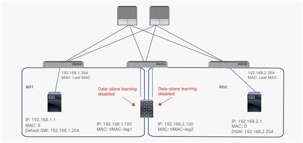
PBR node in the consumer and provider bridge domains
Rewrite source MAC for L4-L7 devices configured for “source MAC based forwarding”
Prior to APIC Release 5.0, ACI PBR rewrote the destination MAC to make traffic go to a PBR node but it didn’t change the source MAC. Therefore, the PBR node receives a traffic with source MAC address of the source endpoint instead of the service BD MAC owned by ACI fabric, which could cause a problem if the PBR node uses “source MAC based forwarding” instead of IP based forwarding.
Starting from APIC release 5.0, the Rewrite source MAC option has been introduced, which provides the option to rewrite source MAC. By default, “Rewrite source MAC” is disabled. This feature requires Cisco Nexus 9300-EX and -FX platform leaf switches onward.
Note: Each service node vendor may have different terminology for “source MAC based forwarding”. For example, it’s called “Auto Last Hop” on F5 BIG-IP and “MAC-Based Forwarding (MBF)” on Citrix NetScaler.
Figure 84 and 85 illustrate a packet walk of traffic forwarding with Rewrite source MAC option. Figure 84 illustrates the incoming traffic from the consumer to the provider endpoint. When the traffic from Web as consumer to App as provider is redirected by a leaf, destination MAC is rewritten to the PBR destination MAC, source MAC is rewritten to the service BD MAC(00:22:bd:f8:19:ff), and the traffic arrives on the PBR node. If source MAC based forwarding is enabled on the PBR node, the PBR node remembers the flow and uses the source MAC (00:22:bd:f8:19:ff) as destination MAC for the return traffic. Then, the traffic arrives at the destination that is the App endpoint.
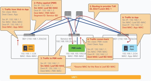
Rewrite source MAC packet walk (incoming traffic from consumer to provider)
Figure 85 illustrates the return traffic from provider to consumer endpoint. When the traffic from App as provider to Web as consumer is redirected by a leaf, destination MAC is rewritten to the PBR destination MAC and the traffic arrives on the PBR node. If the PBR node uses source MAC based forwarding, the service BD MAC (00:22:bd:f8:19:ff) is used as the destination MAC. Thus, traffic can go to the destination that is the Web endpoint through the service leaf. If source MAC was not rewritten in the incoming traffic flow, PBR node uses the Web-MAC as the destination MAC and the service leaf would drop the traffic because the Web-MAC is not in the service BD.
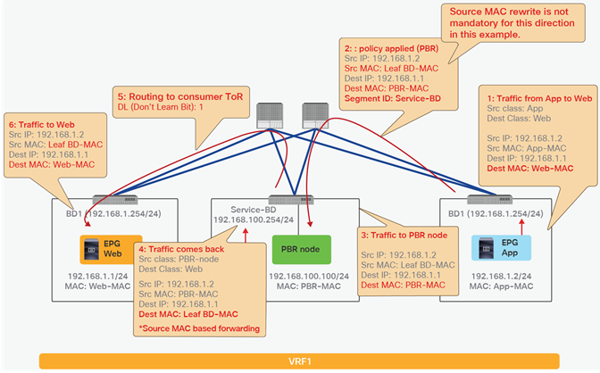
Rewrite source MAC packet walk (return traffic from provider to consumer traffic)
Note: In this traffic flow example, Rewrite source MAC is not mandatory for provider to consumer direction if traffic is always initiated from consumer to provider.
If the L4-L7 device (PBR node) is deployed with the interface in the same bridge domain subnet as the destination:
● Routing is not required for the traffic coming back from PBR node to destination because the L4-L7 device is in the same subnet as the destination.
● The Rewrite source MAC feature is not required either (even though “source MAC based forwarding” is enabled on the PBR node) because the destination MAC is correct and reachable in the BD. Figure 86 illustrates an example.
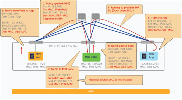
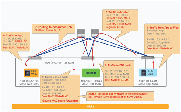
Rewrite source MAC is not required if the destination and the PBR node are in the same subnet.
Destination Name based sorting
Prior to APIC Release 4.2(5) or 5.0, Symmetric PBR uses IP based sorting. If there are multiple PBR destinations, they should be in the same order, and not in a random order of the IP addresses. If a PBR node has two interfaces and one has the smallest IP address in a destination group, the other interface IP address must be the smallest in the other PBR policy to make sure that incoming and return traffic goes to the same device. For example, a device with 10.1.1.1 in Figure 87 must use 10.1.2.1, and another device with 10.1.1.2 must use 10.1.2.2, and so on to keep traffic symmetric for both the incoming and the return traffic.
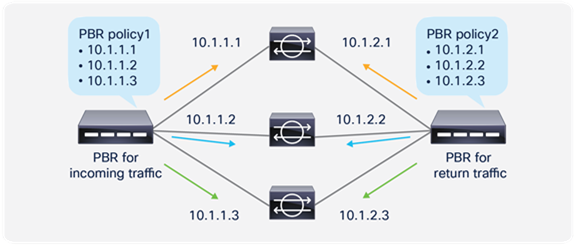
IP based sorting for Symmetric PBR (default behavior)
Starting from APIC Release 4.2(5) and 5.0, Destination Name based sorting is available for the situation where PBR destination IP addresses are not in order. For example, a device with 10.1.1.1 in Figure 88 uses 10.1.2.3 that is not the smallest IP on the other side, which requires Destination Name based sorting. If Destination Name based sorting is used, you must configure Destination Name accordingly to keep traffic symmetric. Destination Name for each PBR destination in PBR policies for the incoming and the return traffic don’t have to be exactly same, but the name based order must be same to keep traffic symmetric.
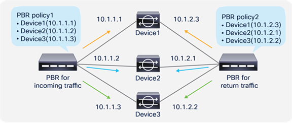
Destination Name based sorting for symmetric PBR
Starting from APIC Release 5.0, L1/L2 symmetric PBR is supported. In case of L1/L2 Symmetric PBR, it’s always Destination Name based sorting.
Prior to APIC release 6.0, there is no option to specify weight for each PBR destination. Thus, the assumption is that PBR destinations (service devices) in the same PBR policy have same or similar capacity to handle traffic.
Starting with APIC Release 6.0, weight can be configured per PBR destination. It can cover the situation where a PBR policy has the mix of service devices that have different capacities.
By default, weight is set to 1 for all of PBR destinations. The configurable weight range is 1 to 10. The total number of weights per PBR policy is up to 128 if PBR destinations are in a BD and it is 64 if PBR destinations are in an L3Out. It is the total # of weights for primary PBR destinations AND backup PBR destinations.
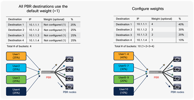
Weight per PBR destination
To keep traffic symmetric, you must use same weights in PBR policies for consumer to provider and provider to consumer direction. The figure below illustrates an example.
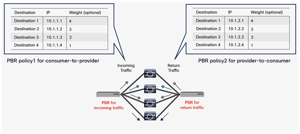
Weight option consideration: use of the same weight
Threshold is calculated based on the total weights of available PBR destinations and total weights of configured PBR destinations. The figure below illustrates an example. In this example, the total weights of configured PBR destination is 10. If 10.1.1.1 is down, the total weights of available PBR destinations is 6. Thus, it’s 60%.
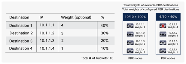
Weight option consideration: threshold
This section describes the configuration of Cisco PBR. It presents the basic configuration and then presents examples of one-arm mode, inter-VRF, and symmetric PBR configurations, plus some optional configurations.
This section presents the basic configuration steps for an unmanaged mode service graph with PBR, using Figure 92 as an example. The basic Cisco ACI configuration is outside the scope of this document. (For example, fabric discovery, interface policy, physical and virtual domain, VRF, EPG, and contract configurations are not discussed).
Note: This document shows the GUI navigations in several APIC releases depending on which release features are introduced. Thus, GUI navigation in this document might be a little different from your APIC GUI. For example, starting with APIC Release 3.1, Protocol Policies and L4-L7 Services are located in different places, as shown in Table 18.
Table 18. GUI configuration locations
| Prior to Cisco APIC Release 3.1 |
Cisco APIC Release 3.1 and later |
| Tenant > Networking > Protocol Policies |
Tenant > Policies > Protocol |
| Tenant > L4-L7 Services |
Tenant > Services > L4-L7 |
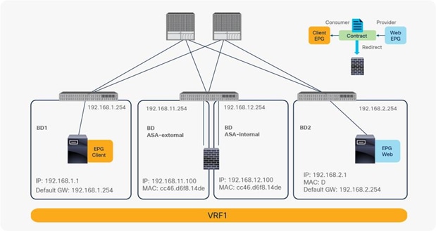
One-node PBR design example (two-arm mode)
Create the PBR node bridge domain
Create the bridge domains for the PBR node. If you are using an APIC version prior to APIC Release 3.1 or first-generation Cisco Nexus 9300 platform switches, you must disable Endpoint Dataplane Learning for the PBR node bridge domains. Starting from APIC Release 5.0(1), this option has been moved under the “Advanced/Troubleshooting” tab under the Policy tab at a bride domain. In the example in Figure 93, Endpoint Dataplane Learning is disabled in the ASA-external bridge domain and ASA-internal bridge domain.
The location is Tenant > Networking > Bridge Domains.
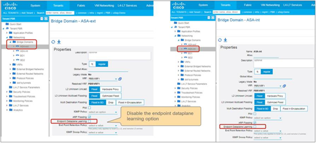
Disable data-plane IP learning for the PBR bridge domains
Create PBR policy
Create PBR policy. You must configure the PBR node IP address and MAC address. This example uses 192.168.11.100 with MAC CC:46:D6:F8:14:DE for the external side and 192.168.12.100 with MAC CC:46:D6:F8:14:DE for the internal side (Figure 94).
The location is Tenant > Policies > Protocol > L4-L7 Policy Based Redirect.
Starting with APIC Release 5.2, MAC configuration is not mandatory for L3 PBR if IP-SLA tracking is enabled. You can leave the MAC configuration empty or configure it to 00:00:00:00:00:00.
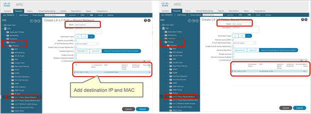
Create the PBR policy
Create the L4-L7 Device
Create the L4-L7 Device. The L4-L7 device configuration has no PBR-specific configuration. You can configure one or more L4-L7 devices. In this example, two devices are configured, Device1 and Device2, as an active-standby high-availability cluster pair. The PBR node IP and MAC addresses defined in L4-L7 Policy Based Redirect are the virtual IP and MAC addresses for the active/standby high-availability cluster pair (Figure 95).
The location is Tenant > Services > L4-L7 > Devices.
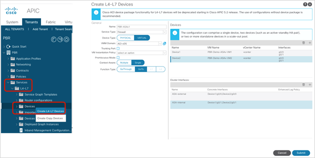
Create the L4-L7 Device
Depending on the design, the following port-group related configuration options need to be enabled:
● Promiscuous mod – A port-group with promiscuous mode is required if the L4-L7 virtual appliance needs to receive traffic destined to a MAC that is not the vNIC MAC owned by the VM. By default, promiscuous mode is disabled on the port-group created through service graph deployment using a go-to mode L4-L7 device. By checking this option in the Create L4-L7 Device configuration, promiscuous mode is enabled on the port-group.
● Trunk port groups –By default, the ACI service graph configuration creates access mode port-groups and attaches the vNIC of the L4-L7 VM automatically to it. Thus, the L4-L7 VM receives untagged traffic. If instead, you want the L4-L7 VM to send and receive tagged traffic, you can use a trunk port-group. By checking this option in the Create L4-L7 Device configuration, automatic vNIC placement does not occur. This option is available starting from Cisco ACI Release 2.1. As the service graph with this option doesn’t take care of trunk port-group creation or automatic vNIC placement for the VM, you need to create a trunk port-group that allows necessary VLANs and attach the trunk port-group to the vNIC of the VM in addition to the service graph configuration. The trunk port-group can be created at Virtual Networking > VMware > Domain name > Trunk Port Groups (Figure 96). When using trunk port-groups, the service graph deployment doesn’t automatically generate a VLAN for the cluster interface, nor does it place the vNIC automatically. Hence, the administrator must associate the L4-L7 device cluster interface to the correct VLAN that is configured on the L4-L7 device similarly to the deployment with physical domains. To configure L4-L7 VM interfaces by using correct VLAN IDs, it is necessary to use static VLAN allocation instead of dynamic VLAN allocation. By default, VLAN IDs for L4-L7 device interfaces are dynamically allocated in the case of an L4-L7 device in a VMM domain, but you can add a static VLAN range to a dynamic VLAN pool. The VLAN encap can be assigned statically to the cluster interface by checking the “Encap” box at the cluster interface configuration (Figure 96).
● Enhanced LAG policy – If the VMware vDS used for the VMM domain has VMware link aggregation groups (LAGs), you need to specify an LAG policy for each cluster interface that is the LAG policy for the port-group created through service graph deployment. This option is available starting from Cisco ACI Release 5.2.
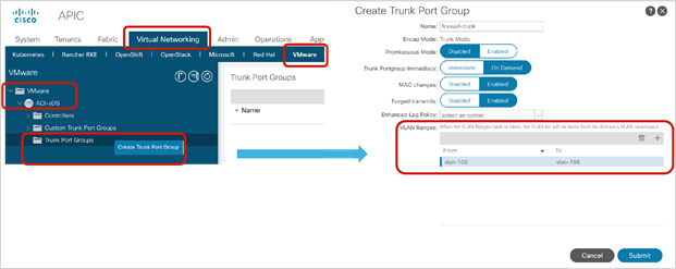
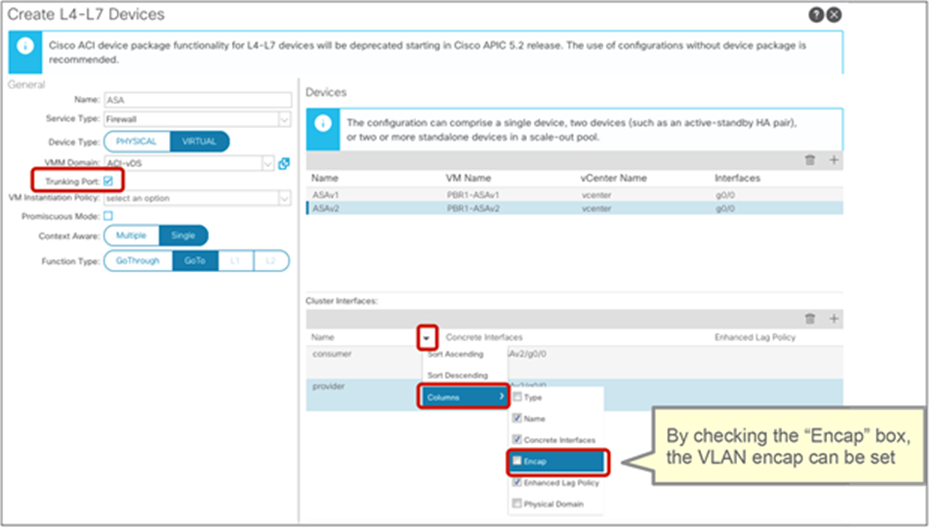
Virtual appliances with a trunk port-group configuration
Create the Service Graph Template
Create the Service Graph Template using the L4-L7 Device that you created. Route Redirect must be enabled to use PBR on the node (Figure 97).
The location is Tenant > Services > L4-L7 > Service Graph Templates.
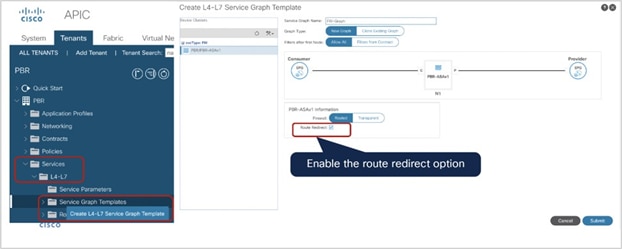
Create the Service Graph Template
Starting from APIC Release 4.2(3), filters-from-contract option is introduced. Please refer “Filters-from-contract option” section for detail.
Create the Device Selection Policy
Create the Device Selection Policy to specify the bridge domains and PBR policy for the consumer and provider connectors of the service node. In the example in Figure 98, the consumer side of the service node is in the “ASA-ext” bridge domain and uses ASA-external PBR policy that you previously created. The provider side of the service node is in the “ASA-in” bridge domain and uses the ASA-internal PBR policy. As a result, consumer-to-provider EPG traffic will be redirected to ASA-external (192.168.11.100 with CC:46:D6:F8:14:DE), and provider-to-consumer EPG traffic will be redirected to ASA-internal (192.168.12.100 with CC:46:D6:F8:14:DE).
The location is Tenant > Services > L4-L7 > Device Selection Policies.
If you use the Apply Service Graph Template wizard, the device selection policy will be created through the wizard.
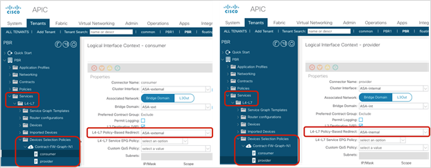
Create the device selection policy (two-arm mode)
Apply the Service Graph to a contract
Apply the Service Graph Template to a contract subject. In this example, Service Graph Template FW-Graph is applied to the contract between the client EPG and the web EPG (Figure 99).
The location is Tenant > Contracts > Standard > Contract.
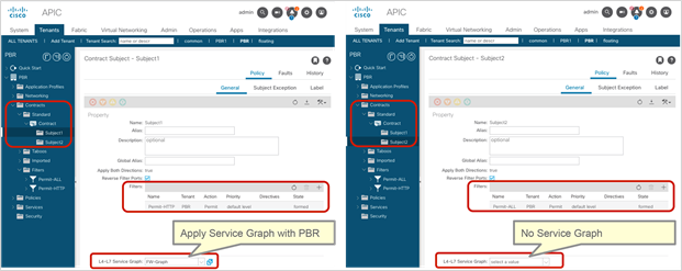
Apply the Service Graph to a contract
PBR is applied based on the filter in the contract subject. So if you apply the Service Graph Template to a contract subject with the Permit-HTTP filter, and if the other subject has the Permit-ALL filter, only the HTTP traffic is redirected (Figure 100).
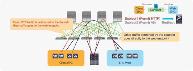
Apply the Service Graph to a contract
The order of subjects doesn’t matter. The more specific filter takes precedence. So if you apply a service graph template with PBR enabled to a contract subject with the Permit-ALL filter, and if the other subject has the Permit-HTTP filter without a service graph, all traffic except HTTP traffic is redirected.
GUI and CLI output example for verification
After a service graph template is successfully applied, you can see the deployed graph instance. If you are using managed mode, you will see the deployed devices as well (Figure 101).
If service graph instantiation fails, you will see faults in the deployed graph instance. For example, if no device selection policy is configured, managed mode L4-L7 parameters are not configured correctly, and so on.
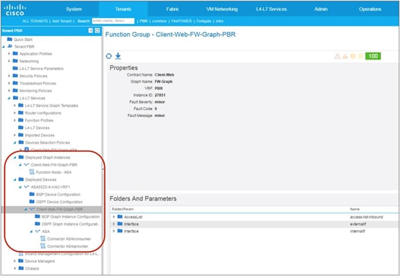
Deployed graph instance and deployed devices
As described in the previous section, the PBR policy is programmed on the consumer and provider leaf nodes. Figure 102 and 103 show examples before and after service graph deployment. In these examples, the consumer EPG class ID is 32771, and the provider EPG class ID is 49154.
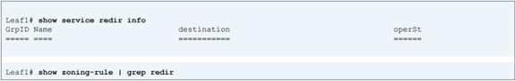
Destination group and redirect policy (before service graph deployment)
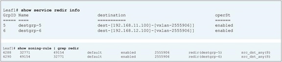
Destination group and redirect policy (after service graph deployment)
If you want to verify whether traffic is actually redirected to the PBR node, you can capture that information on the PBR node. Figure 104 shows an example using Cisco ASA. The ASA can enable real-time capture from the Command-Line Interface (CLI) or GUI. In this example, 192.168.1.1 tries to ping 192.168.2.1 and to access 192.168.2.1:80. Because the service graph with PBR is applied with the Permit HTTP filter, only HTTP traffic is redirected. Thus, the ASA can see the HTTP traffic but not the ICMP traffic.
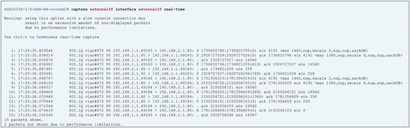
Cisco ASA screen capture example
One-arm mode PBR configuration example
This section presents considerations for a one-arm-mode PBR configuration, using Figure 105 as an example. In this example, the consumer and provider EPGs are in the same bridge domain subnet, but they could be in different bridge domain subnets.
This discussion assumes that you have already completed basic Cisco ACI configuration and PBR-related configuration (for example, that you have configured the PBR node bridge domain, PBR policy, L4-L7 device, and service graph template).
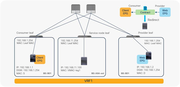
One-node PBR design example (one-arm mode)
Device Selection policy considerations
Although PBR node has one interface, the device selection policy has both consumer and provider connector configuration settings. For a one-arm mode service graph, you just select the same options for both the consumer and provider connectors in the device selection policy, so that only one segment is deployed for the one interface during service graph instantiation (Figure 106).
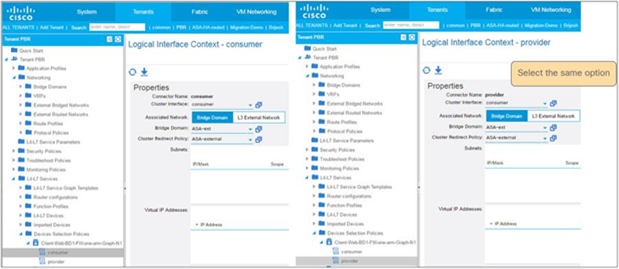
Device selection policy (one-arm mode)
Firewall configuration considerations
The firewall may deny traffic coming into and going out through the same interface. You should configure the firewall to permit intra-interface traffic. For example, Cisco ASA denies intra-interface traffic by default. To allow intra-interface traffic, configure same-security-traffic permit intra-interface on the ASA. If you are using a managed mode service graph, this configuration is available under the L4-L7 Device setting (Figure 107).
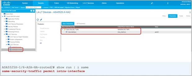
Configure same-security-traffic permit intra-interface
Address Resolution Protocol (ARP) behavior considerations
This section explains why common default filter (Permit All) that includes non-IP traffic shouldn’t be used for PBR using one-arm mode PBR design as an example. When configuring PBR between EPGs that are in the same bridge domain, you should not use a Permit All contract filter, because this filter would also redirect Address Resolution Protocol (ARP) traffic to the L4-L7 device (Figure 108). Though ARP is used in this example, same consideration is applied to exclude ICMPv6 traffic from IP and IPv6 filter.
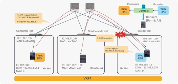
ARP considerations example
If the contract subject filter is not set to Permit All—for instance, if it is set to Permit ICMP, Permit HTTP, or a precise filter that does not include ARP—it will work fine because ARP traffic is not redirected.
Figure 109 and Figure 110 show configuration examples and how it works. The order of the subjects doesn’t matter; the most precise filter will take precedence so only the HTTP traffic between the Client EPG and Web EPG will be redirected.
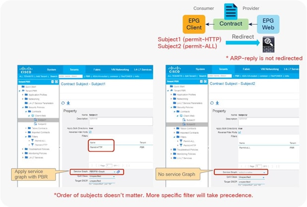
Example of contract subject configuration to exclude ARP reply
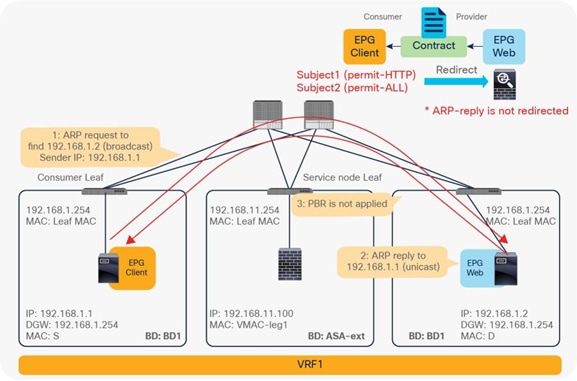
ARP reply traffic is not redirected
Inter-VRF configuration example
This section presents considerations for an inter-VRF PBR configuration, using Figure 111 as an example. In this example, the consumer and provider EPGs are in different VRF instances, and the PBR node is between the VRF instances.
This discussion assumes that you have already performed basic Cisco ACI configuration and PBR-related configuration (for example, you have configured the PBR node bridge domain, PBR policy, L4-L7 device, and service graph template).
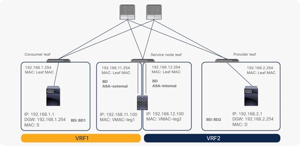
Inter-VRF design example
Route-leaking configuration for consumer and provider bridge domains
In an inter-VRF design, the EPG subnet must be leaked to the other VRF instance to derive the EPG class ID as described in the Deployment options section. To leak the subnet to another VRF instance, the subnet scope must be Shared between VRFs. The subnet under the bridge domain for the consumer EPG and the subnet under the provider EPG must be configured with the setting Shared between VRFs, which is same as with inter-VRF contract configuration. PBR node bridge domain subnets do not need to be leaked, because they will not be destination IP addresses in this example (Figure 112).
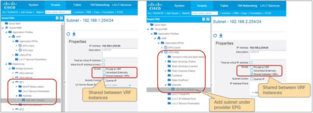
Route-leaking configuration example
Route-leaking configuration for the PBR node bridge domain
If you need to allow direct communication between the consumer and provider EPGs and the PBR node, you must also leak the PBR node subnet to the other VRF instance and set the Direct Connect option to True. Figure 113 shows the topology example. The 192.168.11.0/24 subnet in which the PBR node consumer side is located must be leaked to VRF1.
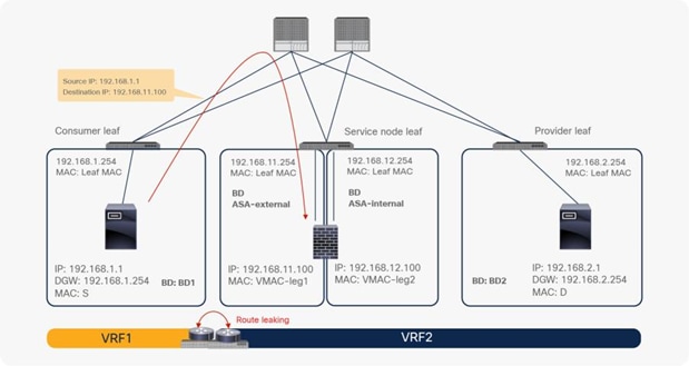
Topology for route leaking
If the PBR node subnet needs to be leaked to the consumer VRF instance, as shown in Figure 113, you need to add the subnet in the device selection policy (Figure 114). This configuration is similar to the configuration of a subnet under the provider EPG, but it is in a different location because the service node EPG does not show up as a regular EPG.
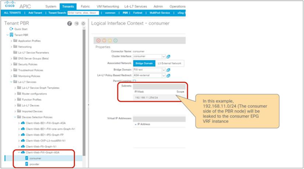
Device selection policy configuration example
If the PBR node subnet needs to be leaked to the provider VRF instance, as in Figure 115, the PBR node bridge domain (ASA-internal bridge domain in this example) must be configured with the Shared between VRFs option enabled. However, you do not need to add the subnet in the device selection policy because the subnet in the consumer bridge domain is leaked to the provider VRF instance.
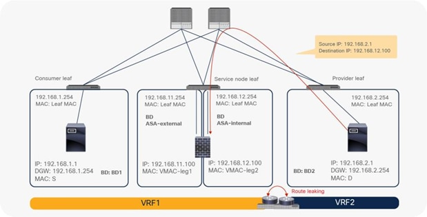
Topology for leaking PBR node subnet to the provider VRF instances
Reuse the same PBR node interface for intra-VRF and inter-VRF contracts
If you want to use the same PBR node and its interface for inter-VRF and intra-VRF contracts, the same Context Name needs to be set in Device Selection Policies for those intra-VRF and inter-VRF contracts. The reason is that class ID allocations for service nodes is per VRF that is also called “context”. As we need to use same class ID for the interface used for both contracts, the same Context Name needs to be used for both service graph deployments.
For example, Contract1 is for intra-VRF communication within VRF1 and Contract2 is for inter-VRF communication across VRF1 and VRF2, and both of them use the same firewall interface, ASA-external (Figure 116). Device Selection policy for Contract1 and Device Selection policy for Contract2 need to have the same Context Name configured (Figure 117).
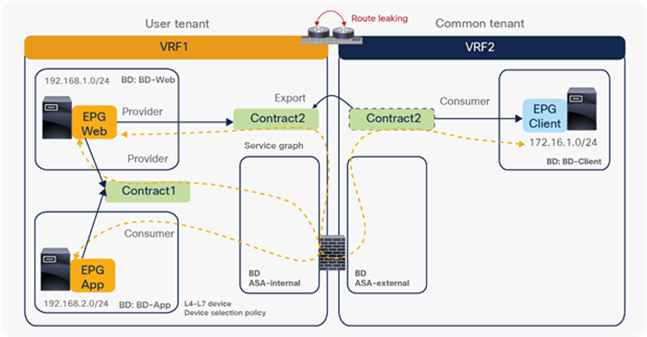
Reuse the same PBR node and its interface for intra-VRF and inter-VRF contract
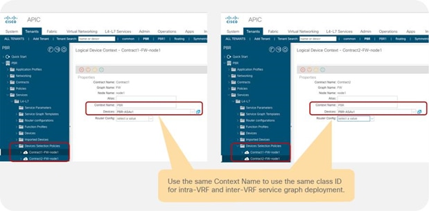
Use the same Context Name in Device Selection Policies
Inter-tenant configuration
The consumer and provider VRF instances can be in different tenants. In addition to the inter-VRF configuration, several other important configuration considerations apply to the inter-tenant service graph:
● Objects defined in the common tenant can be referenced from other tenants, but objects defined in a user tenant can be referenced only from the same tenant.
● The contract must be visible from the provider and consumer EPGs.
● The service graph template must be visible from the contract.
● The L4-L7 device must be visible from the device selection policy.
● The device selection policy must be defined under the provider EPG tenant. This object must be able to see the cluster interfaces in the L4-L7 device and the PBR bridge domains.
Figure 118 shows a configuration example in which the provider EPG is in VRF1 in the common tenant and the consumer EPG is in VRF2 in a user tenant:
● The contract is defined in the common tenant so that it is visible from both the consumer and provider EPGs.
● The device selection policy is defined in the common tenant because the provider EPG is in the common tenant.
● The L4-L7 device and service graph template are defined in the common tenant so that the contract can refer to the service graph template.
● PBR bridge domains in VRF1 are defined in the common tenant so that the device selection policy can refer to the cluster interfaces in the L4-L7 device and the PBR bridge domains.
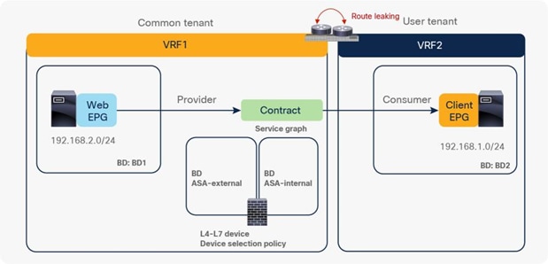
Example of inter-tenant service graph with PBR configuration (provider EPG is in the common tenant)
Figure 119 shows a configuration example in which the consumer EPG is in VRF1 in the common tenant and the provider EPG is in VRF2 in a user tenant:
● The contract is defined in the user tenant and is exported to the common tenant so that it is visible from both the consumer and provider EPGs.
● The device selection policy is defined in the user tenant because the provider EPG is in a user tenant.
● The L4-L7 device is defined in a user tenant, or it is defined in a common tenant and is exported to the user tenant.
● The service graph template is defined in the user tenant because the contract is defined in the user tenant so that the contract can refer to the service graph template.
● PBR bridge domains can be in VRF1 in the common tenant or in VRF2 in the user tenant because objects defined in the common tenant or the user tenant are visible from the device selection policy in the user tenant.
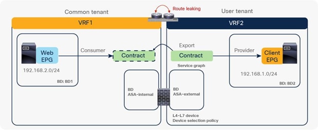
Example of inter-tenant service graph with PBR configuration (consumer EPG is in the common tenant)
The two examples above use a contract between a common tenant and a user tenant. When it is a contract between user tenants, it is similar to the first example with contract export.
Figure 120 shows a configuration example in which the provider EPG is in VRF2 in a user tenant and the consumer EPG is in VRF1 in another user tenant:
● The contract is defined in the provider tenant and is exported to the consumer tenant so that it is visible from both the consumer and provider EPGs.
● The device selection policy is defined in the provider tenant because the provider EPG is in the provider tenant.
● The L4-L7 device and service graph template are defined in the provider tenant so that the contract can refer to the service graph template.
● PBR bridge domains in VRF2 are defined in the provider tenant so that the device selection policy can refer to the cluster interfaces in the L4-L7 device and the PBR bridge domains.
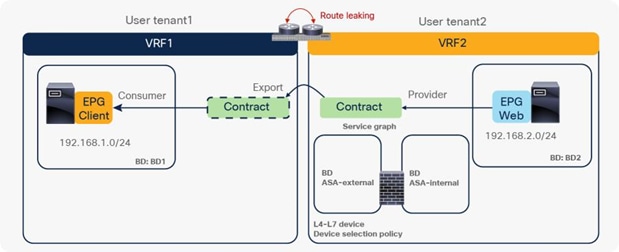
Example of inter-tenant service graph with PBR configuration (both tenants are user tenants)
Unidirectional PBR configuration example
This section presents a unidirectional PBR configuration example. Except for the configuration of the Device Selection Policies, the configuration of unidirectional PBR is the same as the basic PBR configuration described earlier in this document.
The location is Tenant > Services > L4-L7 > Device Selection Policies.
If this is for unidirectional PBR for load balancer without source NAT (Figure 121), both connectors are in a BD, and PBR is enabled on either the consumer or provider connector and is not enabled on the other connector.
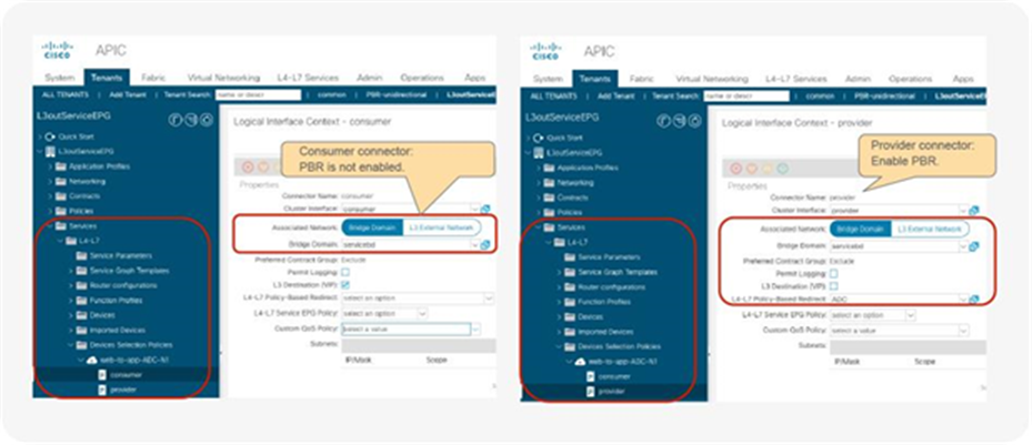
Create Device Selection Policies for unidirectional PBR
If this is for unidirectional PBR with the other connector in L3Out (Figure 122), PBR is enabled on the consumer connector in a BD and is not enabled on the provider connector in L3Out. Destination VIP should be disabled on the provider connector in L3Out because enabling it will create an additional zoning-rule that is not required for this use case.
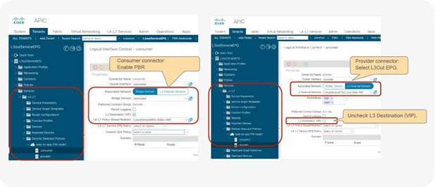
Create PBR policy for unidirectional PBR with the other connector in L3out (PBR is enabled on consumer connector)
If this is for unidirectional PBR with the other connector in L3Out (Figure 123), PBR is enabled on the provider connector in a BD and is not enabled on the consumer connector in L3Out.
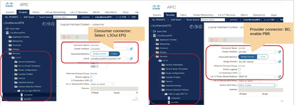
Create PBR policy for unidirectional PBR with the other connector in L3out (PBR is enabled on provider connector)
Symmetric PBR configuration example
This section presents a symmetric PBR configuration example. Except for the configuration of the PBR policy and L4-L7 device, the configuration of symmetric PBR is the same as the basic PBR configuration described earlier in this document.
Create a PBR policy with multiple PBR destinations (Figure 124). Starting from APIC Release 5.2, MAC configuration is not mandatory for L3 PBR if IP-SLA tracking is enabled. You can leave the MAC configuration empty or configure it as 00:00:00:00:00:00. Starting with APIC Release 6.0, weight can be configured per PBR policy. By default, weight is set to 1 for all of PBR destinations.
The location is Tenant > Protocol > Policies > L4-L7 Policy Based Redirect.
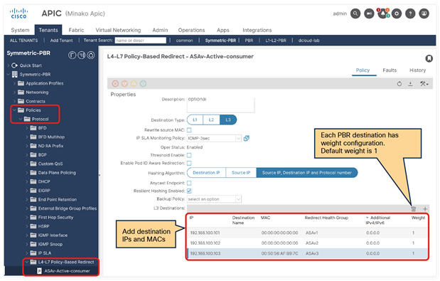
Create PBR policy
Note: By default, the order of the IP addresses in a destination group is important. If there are multiple PBR nodes, they should be in the same order, and not in a random order of the IP addresses. If a PBR node has two interfaces and one has the smallest IP address in a destination group, the other interface IP address must be the smallest in the other destination group to make sure that incoming and return traffic goes to the same PBR node. For example, a device with 192.168.11.101 in Figure 124 must use 192.168.12.101, and another device with 192.168.11.102 must use 192.168.12.102, and so on. Starting from APIC release 4.2(5) and 5.0, Destination Name option is added to use Destination Name based sorting instead of IP address based sorting for the situation where PBR destination IP addresses are not in order. Please see Destination Name section for how to configure Destination Name.
Create L4-L7 devices with multiple concrete devices. Symmetric PBR is supported with an unmanaged mode service graph only because configuration of each PBR node is unique (Figure 125).
The location is Tenant > Services > L4-L7 > Devices.
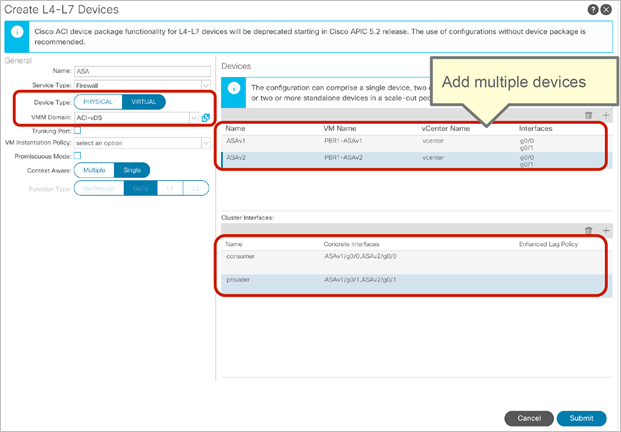
Create L4-L7 devices: CLI output example for verification
As in the previous example, redirect policy is programmed on the consumer and provider leaf node, which is between the consumer class ID and provider class ID. Compared with the case of a single PBR node, this example has multiple destinations in the “service redir info” (Figure 126 and Figure 127).
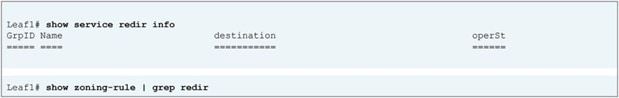
Destination group and redirect policy (before service graph deployment)
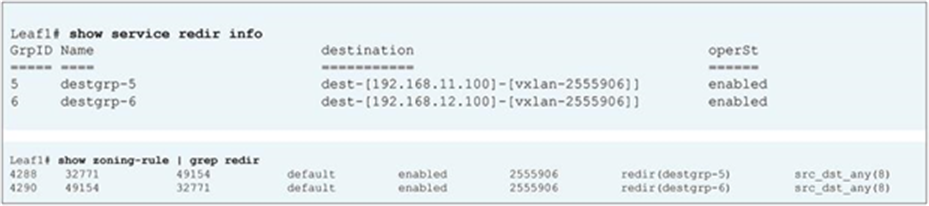
Destination group and redirect policy (after service graph deployment)
This section presents optional configurations for PBR.
Hashing algorithm configuration
Figure 128 shows the hashing algorithm configuration.
The location is Tenant > Policies > > Protocol > L4-L7 Policy Based Redirect. The default setting is Source IP, Destination IP and Protocol number.
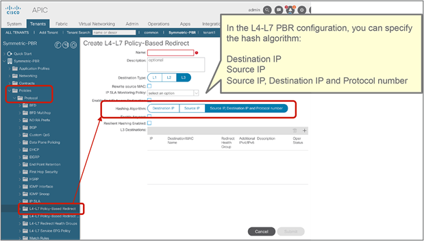
Hashing algorithm
PBR node tracking configuration
You can enable tracking on each L4-L7 PBR node (Figure 129). The location is Tenant > Policies > Protocol Policies > L4-L7 Policy Based Redirect.
For the tracking feature, you can also configure the threshold, down action, IP Service-Level Agreement (SLA) monitoring policy, Resilient Hashing, Backup PBR policy, and the health group for each destination on each L4-L7 PBR node.
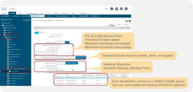
L4-L7 PBR tracking, health group, down action and threshold configuration
Design considerations:
● To enable tracking, the IP SLA Monitoring Policy and Health Group must be set.
● By default, the IP address (the primary IP address) defined in the destination will be tracked. You also can add an IPv4/IPv6 address to track. If you configure both the primary and additional IP addresses, when both are up the PBR node is marked as Up.
● If a threshold is not enabled, and all of the PBR destinations in the PBR policy are down, the traffic is dropped.
● If a threshold is enabled, you can specify a down action and minimum threshold and maximum threshold percentages. The supported down actions are Permit, Down, and Bypass. By default, the down action is Permit. You should use the same action on both the consumer and provider connectors of the PBR node; otherwise, a fault is raised under the tenant even though the service graph is rendered.
● If tracking and Resilient Hashing are enabled, you can specify a Backup Policy to set backup PBR destination.
Note: If you have multiple PBR policies that have same PBR destination IP in same VRF and tracking is enabled on any of these policies, you need to use same IP-SLA policy and use same health-group for the IP on all of them. It’s because PBR destination uses (VRF, IP) as the key for tracking status. Same PBR destination IP in the VRF can’t have different up/down states. For example, the following configuration is not supported:
● PBR policy1 has PBR destination 192.168.1.1 in VRF A with IP-SLA Monitoring policy1 (ICMP tracking).
● PBR-policy2 has PBR destination 192.168.1.1 in VRF A with IP-SLA Monitoring policy2 (TCP tracking).
You can configure IP SLA monitoring policies (Figure 130).
The location is Tenant > Networking > Protocol Policies > IP SLA Monitoring Policies. By default, this setting is not used in L4-L7 PBR.
You can specify the SLA frequency, SLA port, and SLA type.
The following SLA types are supported:
● TCP for L3 PBR, starting from APIC Release 2.2(3j)
● ICMP for L3 PBR, starting from APIC Release 3.1
● L2Ping for L1/L2 PBR, starting from APIC Release 4.1
● HTTP for L3 PBR, starting from APIC Release 5.2
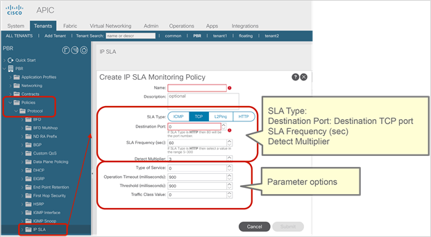
IP SLA monitoring policies
The minimum value for the SLA frequency is 5 seconds for HTTP tracking and 1 second for other SLA types. The detect multiplier is 3 by default, which is configurable in the GUI after APIC Release 4.2. The minimum value for the detect multiplier is 1. For example, if the SLA frequency is 1 second and the detect multiplier is 3, probing of PBR nodes and failure detection work as follows:
● First probe at time T0: failed
● Second probe at time T0 + 1 second: failed
● Third probe at time T0 + 2 seconds: failed and now destination is reported as down
Starting from APIC Release 5.1(3), the following parameter options are supported:
● Request Data Size (bytes) for ICMP, L2Ping or HTTP
● Type of Service (ToS)
● Operation Timeout (milliseconds)
● Threshold (milliseconds)
● Traffic Class Value
Starting from APIC Release 5.2(1), the HTTP SLA type is supported with the following considerations:
● Support only HTTP, not HTTPS
● Support only HTTP version 1.0 and 1.1
● Destination port must be 80
● The minimum value for the SLA frequency is 5 seconds
● The user must configure the URI (not the URL). Domain resolution is not supported. The URI must not be empty and start with “/”
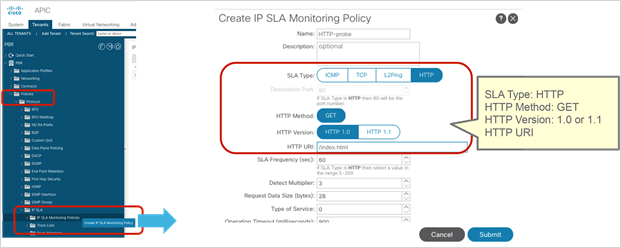
IP SLA monitoring policies (HTTP)
Health group
You can configure health groups (Figure 132).
The location is Tenant > Policies > Protocol > L4-L7 Redirect Health Groups. By default, this setting is not used in L4-L7 PBR.
You create the health groups here. In L4-L7 PBR, you select a health group for each PBR destination IP address, so you can group a consumer side address and a provider side address together.
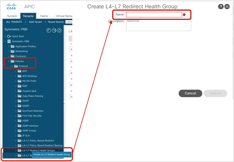
Redirect health group
In the example, three health groups were created (Table 19 and Figure 133).
Table 19. Health groups
| Provider side |
Consumer side |
Health group |
| 192.168.100.101 |
192.168.101.101 |
ASAv1 |
| 192.168.100.102 |
192.168.101.102 |
ASAv2 |
| 192.168.100.103 |
192.168.101.103 |
ASAv3 |
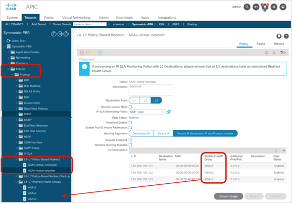
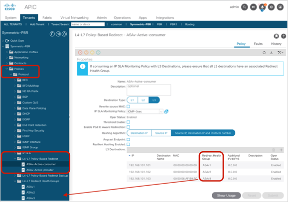
Add destination IP address in redirect health group
Resilient Hashing configuration
You can enable and disable the Resilient Hashing option (Figure 134). The location is Tenant > Policies > Protocol > L4-L7 Policy Based Redirect.
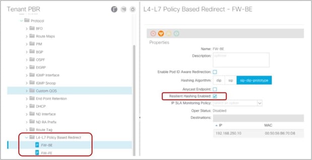
L4-L7 PBR Resilient Hashing option
Backup PBR policies
You can configure Backup PBR policies (Figure 135).
The location is Tenant > Policies > Protocol > L4-L7 Policy Based Redirect Backup.
You create Backup PBR policy here. In L4-L7 PBR, you select a Backup PBR policy so that you can set backup PBR destinations. By default, this setting is not used in L4-L7 PBR, which means there is no backup PBR destination.
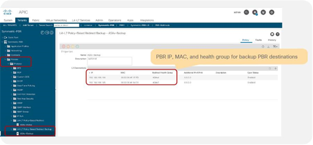
Backup PBR policy
You can specify backup PBR destination IP, MAC, health group, and additional IPv4 or IPv6 address for tracking similar to PBR policy, but not other settings per PBR policy, such as IP SLA monitoring policy and threshold. Backup PBR policy uses the same settings as PBR policy for primary PBR destinations.
Figure 136 shows a CLI output example: 192.168.100.101, 192.168.100.102, and 192.168.100.103 are primary PBR destinations in PBR policy, and 192.168.100.104 and 192.168.100.105 are backup PBR destinations in backup PBR policy.
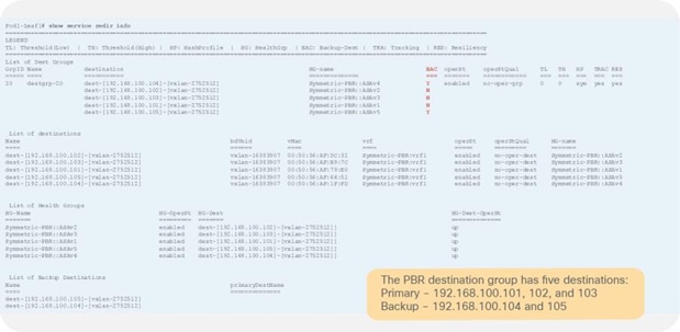
Tracking and backup status on consumer/provider leaf nodes (All PBR destination are UP.)
If one of the primary PBR destinations is down, 192.168.100.104 is used.
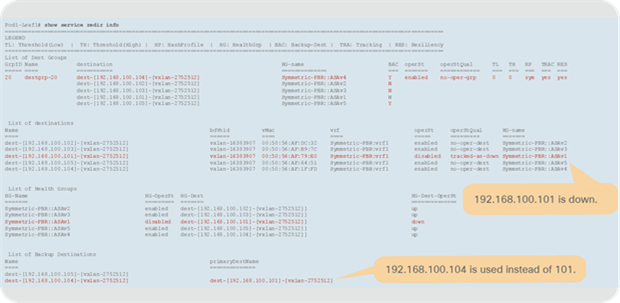
Tracking and backup status on consumer/provider leaf nodes (192.168.100.101 is down.)
Note: When you have multiple available backup PBR destinations, one of the available PBR destinations is used in the order of the IP addresses, from the lowest to the highest. Thus, 192.168.100.104 is used instead of 192.168.100.105 in this example.
If one more PBR destination is down, 192.168.100.105 is used.
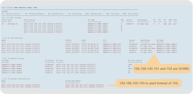
Tracking and backup status on consumer/provider leaf nodes (192.168.100.101 and 192.168.100.102 are down.)
Rewrite source MAC configuration
You can enable and disable the Rewrite source MAC feature as illustrated in Figure 139. The location is Tenant > Policies > Protocol> L4-L7 Policy Based Redirect. By default, Rewrite source MAC is disabled.
Note: When Rewrite source MAC is enabled, the service BD MAC address must be the default 00:22:bd:f8:19:ff. If the administrator configures a different MAC for the service BD, the service graph rendering fails, and the deployed graph instance shows a fault.
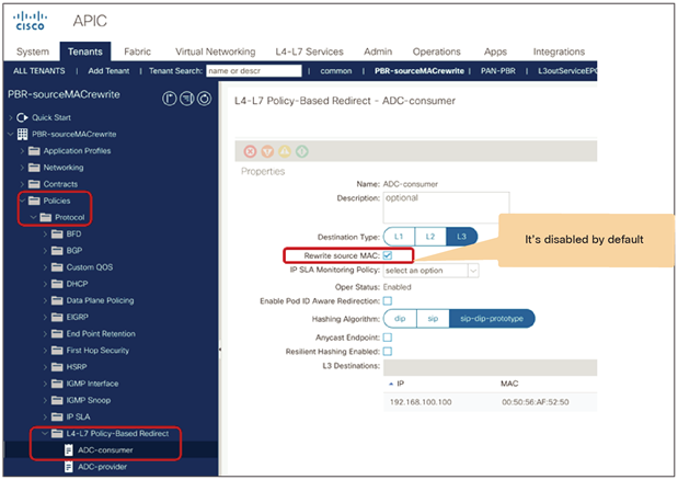
L4-L7 PBR Rewrite source MAC configuration
You can use Destination Name based sorting instead of IP based sorting for symmetric PBR by configuring Destination Name as illustrated in Figure 140. The location is Tenant > Policies > Protocol > L4-L7 Policy Based Redirect. By default, Destination Name based sorting is disabled and IP based sorting is used. In case of L1/L2 Symmetric PBR, it’s always Destination Name based sorting.
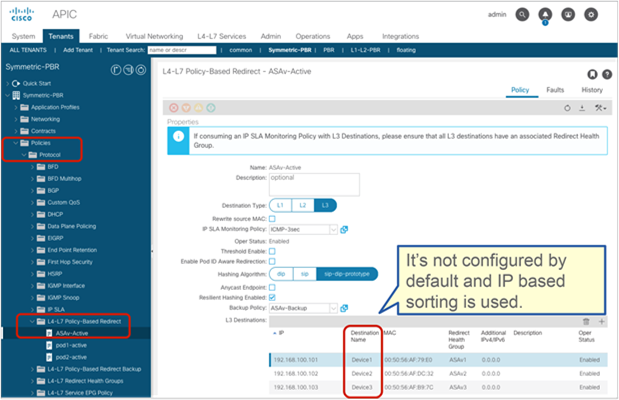
Destination Name configuration
Note: If Destination Name is configured, Destination Name based sorting is used instead of IP based sorting. If a PBR policy has mix of a PBR destination with Destination Name configured and one without Destination Name, service graph rendering is failed. If backup PBR policy is configured, Destination Name must be configured for PBR destinations in the backup PBR policy too.
You can enable location-based PBR on each PBR policy (Figure 141). The location is Tenant > Policies > Protocol > L4-L7 Policy Based Redirect. It is not enabled by default.
Pod ID configuration for each PBR destination is required, and it becomes available if “Enable Pod ID Aware Redirection” is checked.
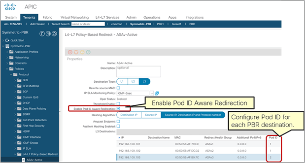
Enable Pod ID Aware Redirection
Note: If multiple PBR policies have the same PBR destination IP in the same VRF, then all the policies must either have Pod ID aware redirection enabled or Pod ID aware redirection disabled. The same (VRF, IP) pair cannot be used in Pod ID aware redirection enabled and Pod ID aware redirection disabled policies at the same time. For example, the following configuration is not supported:
● PBR policy1 has PBR destination 192.168.1.1 in VRF A, Pod ID aware redirection enabled.
● PBR-policy2 has PBR destination 192.168.1.1 in VRF A, Pod ID aware redirection disabled.
Service BD configuration option
Prior to ACI release 6.0(2), traffic received on a service BD is either bridged or routed based on the destination.
● If the destination MAC is the service BD MAC, traffic is routed (L3 traffic)
● If the destination MAC is not the service BD MAC, traffic is bridged (L2 traffic)
Starting from ACI release 6.0(2), regardless it's L3 or L2 traffic, traffic received on a service BD is routed by default. This is to take care of IP based EPG/ESG classification accordingly even if the destination endpoint is in the service BD subnet because IP based classification is not applicable to L2 traffic. The figure below illustrates an example.
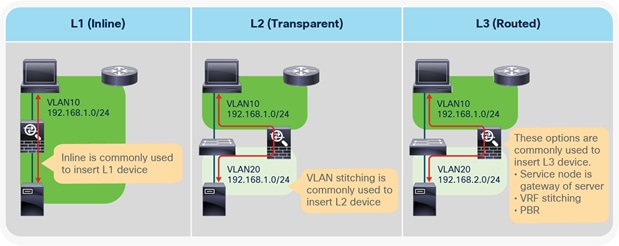
L2 traffic received on a service BD needs to be routed for IP based classification
However, if you still have L2 only traffic in the service BD for some reason such as clustering/HA heartbeat, the behavior prior to 6.0(2) might be required. The figure below illustrates an example.
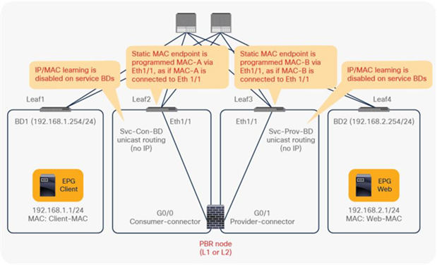
L2 traffic received on a service BD needs to be bridged
Note: This consideration is not applicable for the following cases:
● If ServiceBD1 has a secondary IP for 10.1.1.0/24 subnet, communication between 10.1.1.1 and 10.1.1.2 works because ACI fabric can route the traffic.
● If the traffic is pure ethernet traffic that doesn’t use IP at all, it is still bridged.
The default behavior can be changed per service BD by using the configuration object “serviceBdRoutingDisable” introduced in 6.0(2).
It is set to “no” by default, which means routing is enabled. Since the configuration option is not exposed to GUI as of this writing, the use of REST API is required to set it to “yes” to use the behavior prior to 6.0(2).
{
"fvBD": {
"attributes": {
"serviceBdRoutingDisable": "yes"
}
}
}
Starting from APIC Release 4.1, PBR can be used with L4-L7 service devices operating in L1 or L2 mode; PBR can now be used with inline IPS, transparent firewall (FW), etc. This section explains how L1/L2 PBR works and the L1/L2 PBR configuration. Note that because several designs and traffic flows are possible, the example used in this discussion may not exactly reflect your environment.
Though we have several different terminologies for service-device-deployment modes across different vendors, in this discussion we are going to use the terminologies and definitions given below:
● L1 device
◦ No VLAN translation on a service device
◦ Both service-device interfaces use the same VLAN
◦ Typically called inline mode or wire mode
◦ Typically used for firewall and IPS if the service device is expected to perform security functions not participating in L2 or L3 forwarding
● L2 device
◦ Bridging on a service device (Destination MAC lookup may happen.)
◦ VLAN translation on a service device
◦ Both service-device interfaces use different VLANs
◦ Typically called transparent mode or bridged mode
◦ Typically used for firewall and IPS
● L3 device
◦ Routing on a service device (Destination IP lookup happens.)
◦ Both service-device interfaces use different VLANs
◦ Typically called routed mode
◦ Typically used for firewall and load balancer
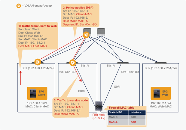
Service device deployment mode comparison
Table 20. Supported deployment modes
| Service device |
L3 (routed mode) |
L2 (transparent mode) |
L1 (inline mode) |
| Cisco Adaptive Security Appliance (ASA) |
YES |
YES |
NO |
| Cisco Firepower NGFW |
YES |
YES |
YES (inline pair) |
| Fortinet NextGen Firewall |
YES |
YES |
YES (virtual wire pairs) |
| Palo Alto Networks Next-Gen Firewall |
YES |
YES |
YES (vWire mode) |
In a typical L1/L2 device insertion design, all traffic across VLANs needs to go through the L1/L2 device because it is always part of the traffic path. By using L1/L2 PBR in ACI, selective traffic redirection is possible based on the contract filter, which is the same advantage as using L3 PBR.
From a Cisco ACI forwarding perspective, there is not much difference between L3 PBR and L1/L2 PBR. Traffic is redirected to a PBR destination MAC that is static MAC endpoint programmed on a leaf interface connected to an L1/L2 device interface. Thus, traffic can be redirected to the leaf interface connected to an L1/L2 device.
Figure 145 shows an example in which the Client EPG is a consumer EPG and the Web EPG is a provider EPG with a contract with the L1/L2 PBR service graph. An endpoint MAC-A is programmed as if MAC-A were connected to Eth1/1 on Leaf2. And an endpoint MAC-B is programmed as if MAC-B were connected to Eth1/1 on Leaf3.
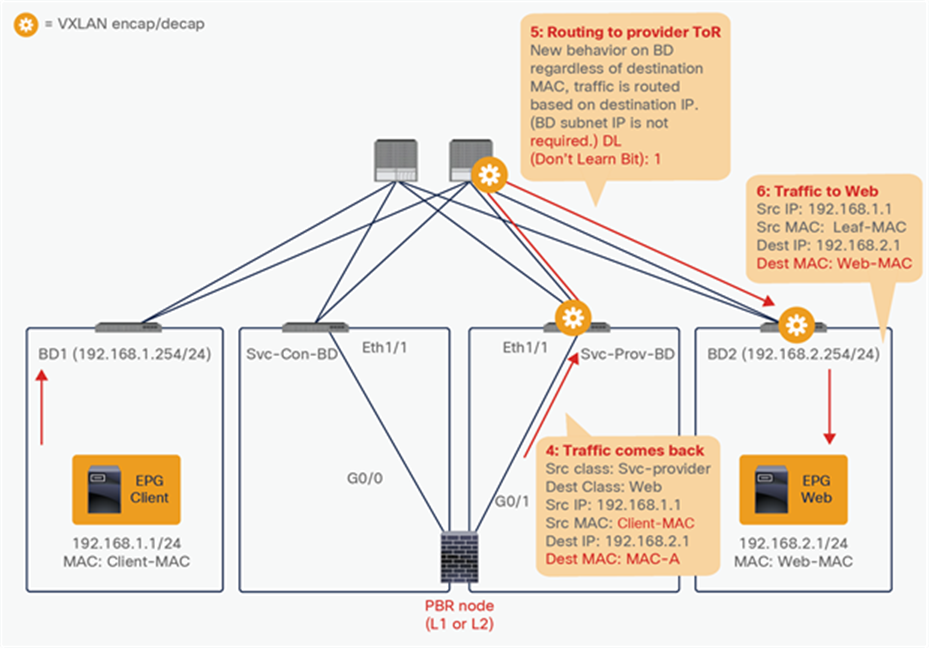
L1/L2 PBR topology example
Note: MAC-A and MAC-B for L1/L2 PBR are automatically generated by APIC by default (it is configurable). L1/L2 PBR device BDs are not automatically created through service graph; they need to be created beforehand. The configuration considerations are following:
● IP routing must be enabled (but no BD subnet is required).
● L2 Unknown Unicast option must be set to Hardware Proxy.
● Dataplane IP learning is automatically disabled; this is similar to the L3 PBR case.
The client endpoint generates traffic destined for the web endpoint. If Leaf1 has already learned the destination endpoint, Leaf1 can resolve the source and destination EPG class IDs, so PBR is performed on Leaf1. Here the destination MAC address is rewritten to the static MAC endpoint MAC-A. It means traffic is redirected to the consumer connector of the PBR device. Redirect traffic destined to a PBR destination is always sent to the L2 spine proxy, then forwarded to the PBR device. As in L3 PBR, Leaf2 does not learn the client IP address from this traffic because Endpoint Dataplane Learning is disabled for the PBR node bridge domain.
Note: Though the destination MAC address is rewritten, the source MAC address is preserved by default. Therefore, the PBR node receives traffic with the source MAC address of the source endpoint. However, that source MAC will not be a destination MAC address of the redirected traffic. Thus, it is recommended to disable MAC address learning on the PBR node. If tracking is enabled, it must be disabled. Please also see the section Active/standby design with tracking.
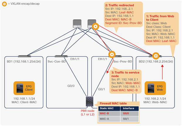
Packet flow example (Client-to-web traffic is redirected to PBR node.)
Then traffic goes through the PBR node and returns to the Cisco ACI fabric.
Note: If the PBR device bridges traffic based on the MAC address table, performing destination MAC lookup, the PBR device must have a MAC address table entry to get traffic to return to the Cisco ACI fabric. For example, Cisco ASA transparent-mode firewall (L2 device) performs destination MAC lookup. Thus, it must have a MAC address table entry that says MAC-A is via G0/1, which is connected to Leaf3 Eth1/1 in this example.
Though PBR node bridge domains do not have a BD subnet, traffic can be routed on Leaf3. Because Leaf3 does not know the destination endpoint (192.168.2.1 in Web EPG), the traffic goes to the L2 spine proxy again and then to Leaf4. Here the source EPG is the PBR node provider connector class ID, and the destination is the provider EPG class ID. The traffic is only permitted and arrives at the web endpoint. The key point here is that Leaf4 does not learn the client IP address from this traffic because Endpoint Dataplane Learning is disabled for the PBR node bridge domain (Figure 147).
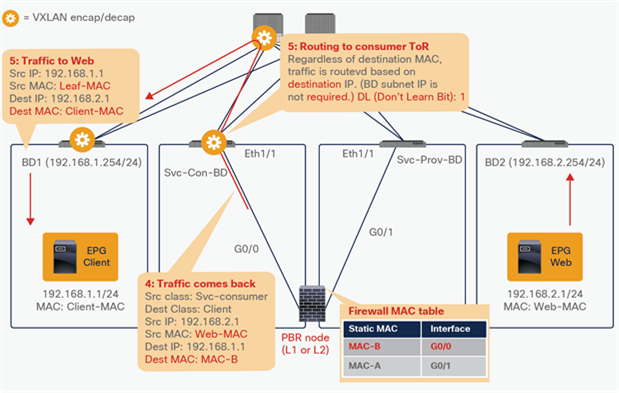
Packet flow example (PBR node to web)
For the return traffic, when PBR is performed, the destination MAC address is rewritten to the static MAC endpoint MAC-B, and the traffic goes to the PBR node on the provider side (Figure 148).
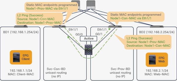
End-to-end packet flow example (Web-to-client traffic is redirected to PBR node.)
The traffic returns to the Cisco ACI fabric from the consumer side of the PBR node. As with consumer-to-provider traffic, Leaf2 does the routing. Because Leaf2 does not know the destination endpoint, the traffic goes to the L2 spine proxy again and then to Leaf1. Leaf1 does not learn the web endpoint IP address from this traffic because Endpoint Dataplane Learning for the PBR node bridge domain is disabled (Figure 149).
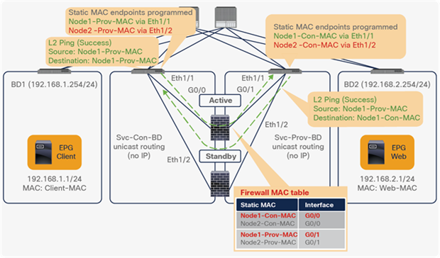
End-to-end packet flow example (PBR node to client)
Note: TTL is decreased because it is routing on leaf node.
Although consumer and provider EPGs are in different BDs in this example, they can be in the same BD and the same BD subnet. Regardless of consumer and provider EPG BD design, the L1/L2 service device can be inserted. This flexibility is one of the advantages of Cisco ACI L1/L2 PBR.
Active/standby design with tracking
Prior to APIC Release 5.0, active/active symmetric PBR design is not applicable to L1/L2 PBR. Active/standby design is supported with tracking in APIC Release 4.1 and 4.2. This section explains how L1/L2 PBR active/standby design with tracking works.
As with tracking in L3 PBR node, the service leaf node to which the PBR node is connected periodically sends keepalive messages and announces availability information to all the other leaf switches. The difference between L3 PBR tracking and L1/2 PBR tracking is that L1/2 PBR tracking uses L2 Ping between leaf switches.
Figure 150 illustrates an example. The Source and Destination MAC addresses of L2 Ping are PBR destination MACs. If the PBR node is up and carries the traffic, L2 Ping should successfully return to the Cisco ACI fabric. The Cisco ACI fabric understands that as meaning the PBR destination is available.
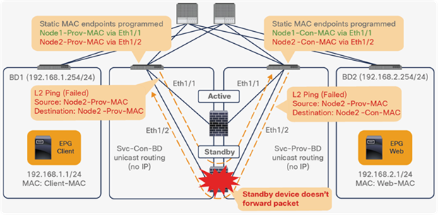
L2 Ping between leaf switches
Note: MAC address learning must be disabled on the PBR node. Otherwise, L2 Ping could cause MAC address flapping on the PBR node because the source MAC address of L2 Ping is the same as the source MAC address for the keepalives to the consumer and the provider connectors, which means the PBR node observes the same source MAC from different interfaces.
Imagine you have active and standby HA L1/L2 service nodes that you want to insert by using L1/2 PBR. You have two PBR destinations and enable tracking. Only one of the paths that is connected to an active node is up, because a standby device does not forward traffic; so traffic is redirected to the interface (Eth1/1 in this example) that is connected to the active node.
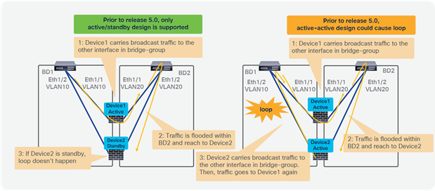
L2 Ping path using an active device is successful
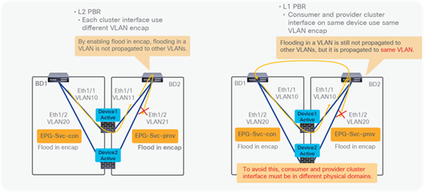
L2 Ping path using a standby device has failed
If failover happens and standby takes over the active role, the tracking status changes and traffic starts being redirected to the interface (E1/2 in this example) that is connected to the new active node.
Starting from APIC Release 5.0, active/active symmetric PBR design is also applicable to L1/L2 PBR. Other Symmetric PBR related features such as threshold, down action and backup PBR policy (N+M high availability) are also available in APIC Release 5.0. This section explains how the L1/L2 PBR active/active feature works and how it differs with the L1/L2 PBR active/standby feature.
The reason why the active/active design is not supported with releases prior to ACI 5.0 is that this could cause a loop if there are multiple active L1/L2 devices in same service bridge domain pair. Figure 153 illustrates an example. With L4-L7 devices operating in active/standby design mode, even if traffic is flooded within a bridge domain and it reaches the second L4-L7 device, a loop doesn’t happen because this device is in standby mode. With an active/active design, the second L4-L7 device would forward the traffic to the other interface in the other bridge domain and the traffic reaches the first device, thus causing a loop.
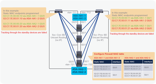
Active/active design is not supported prior to APIC Release 5.0 because it could cause loop
Starting from APIC release 5.0, it is possible to deploy a service graph with L4-L7 devices in active/active mode because the configuration consists of assigning a different encap for each L4-L7 device interface (concrete interface) and because ACI automatically sets “Flood in encap” on the hidden service EPG (which ACI automatically creates to associate the L4-L7 device interface attached to the service bridge domain).
The admin doesn’t need to configure the hidden service EPG, “Flood in encap” is enabled on the service EPGs by ACI automatically during service graph rendering.
The use of L1 PBR active-active designs requires the configuration of the port local scope, which means that the consumer and provider cluster interfaces of the L4-L7 device (consumer and provider “connectors”) must be in different physical domains with different VLAN pools using same VLAN range.
Figure 154 provides example: each active L4-L7 device operating in L2 mode uses different VLAN encap for its consumer and provider interface. Because “Flood in encap” option prevents the flooding propagation across VLANs, a loop doesn’t occur. If the L4-L7 device is operating in L1 mode, the provider and consumer connectors of each active device use same VLAN encapsulation. In order to prevent the flooding propagation in the same VLAN encapsulation for the consumer and provider connector pair, the administrator must use different physical domains with port local scope.
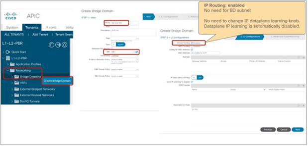
How to prevent loop for active/active L1/L2 PBR
It is also possible to use of multiple active/standby pairs with L1/L2 PBR active/active designs. Figure 155 provides an example. The L2 logical device has 4 concrete devices: firewall pair1 has two active/standby firewalls using VLAN 711 and VLAN 712, and firewall pair2 has different two active/standby firewalls using VLAN 721 and 722. It means 4 PBR destinations but only 2 out of 4 are active, this is hence they are “failed”.
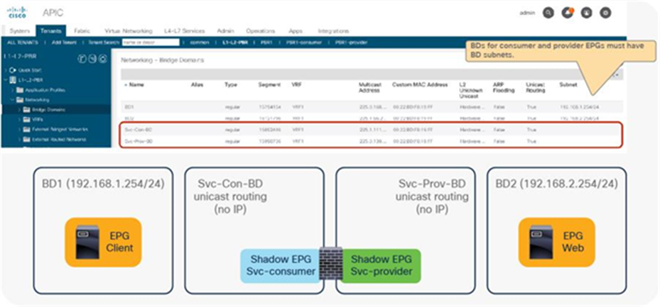
Example of multiple active/standby pairs
Note: Multiple active/standby pairs with L1/L2 PBR active/active design is not supported with backup PBR policy.
L1/L2 PBR configuration
Although L1/L2 PBR configuration flow is similar to L3 PBR, there are couple of requirements on Bridge Domain L4-L7 Device, PBR policy, and tracking configurations. This section covers L1/L2 PBR configuration consideration and examples. For general PBR configurations, please check the previous section.
This section doesn’t cover how to create tenant, VRF, consumer, and provider BD and EPG. The assumption is that there are consumer EPGs, provider EPGs, and BDs that are already configured.
The L1/L2 PBR configuration includes the following steps in this section:
1. Create Bridge Domains for PBR node.
2. Create an L4-L7 device.
3. Create the Service Graph (the same as with L3 PBR).
4. Configure an IP SLA Monitoring policy. (This is mandatory if active/standby firewalls are used)
5. Create a PBR policy.
6. Apply a Service Graph Template to a contract.
The following are optional configurations, CLI commands and configuration considerations covered in this section:
● Change the MAC address of the PBR destination.
● Transparent mode ASA–specific configuration.
● CLI output example for verification.
● L1 Device connectivity considerations.
● Multiple active/standby HA pairs design considerations
Create bridge domains for PBR node
Create BDs for the consumer connector and the provider connector of L1/L2PBR node. The L1/L2 PBR node bridge domains have the following requirements and considerations:
● PBR node bridge domain must be dedicated and cannot be shared with other endpoints.
● PBR node bridge domain must enable a “Unicast Routing” option.
● PBR node bridge domain must be set to “Hardware Proxy” for L2 Unknown Unicast option
● There is no need to change the IP dataplane learning knob, because dataplane IP learning is automatically disabled once Service Graph with PBR is deployed.
Note: During service graph rendering, APIC checks if service BDs for L1/L2 PBR are being configured in multiple device selection policy or being used in an EPG. If yes, APIC raises the fault and service graph rendering is failed even another service graph is not deployed yet.
The location is Tenant > Networking > Bridge Domains
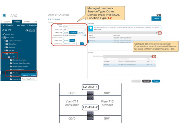
Create bridge domain
Figure 157 shows an example of bridge domain configuration. Even though “Unicast Routing” must be enabled, PBR node bridge domains do not need BD subnet configuration, but consumer and provider bridge domains must have a BD subnet as PBR requires using Cisco ACI fabric as Layer 3.
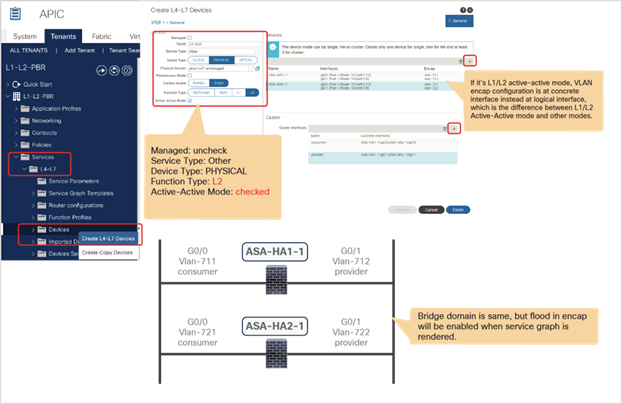
Bridge domain configuration example
Create L4-L7 devices
Create the L4-L7 devices. L4-L7 devices for L1/L2 PBR have the following requirements and considerations:
● Managed option must be unchecked. (Unmanaged mode Service Graph only)
● Service type: Other
● Device type: Physical
● Function type: L1 or L2
● Up to two devices can be configured as a L4-L7 device prior to APIC Release 5.0 because only active/standby design is supported.
● For L1 device, consumer and provider connector must be connected to different leaf.
The location is Tenant > L4-L7 Services > L4-L7 Devices.
Figure 158 is active/standby L2 Device configuration example using APIC Release 4.1. This logical device will be used in the following configuration examples.
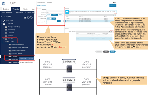
Create L4-L7 Devices (Prior to APIC Release 5.0)
Note: Concrete interface information will be referred in PBR policy configuration for static MAC endpoint programming.
For L1/L2 PBR active/active mode has the following additional configuration considerations:
● VLAN encap configuration is at each concreate interface instead of each cluster interface.
● For L1 device, each cluster interface must be in different physical domains for port local scope.
Figure 159 provides an example of an active/active L2 device configuration using APIC Release 5.0. If this is a deployment with a L4-L7 device operation in L2 active-active mode, the VLAN encap configuration is at each concreate interface instead of each cluster interface. So that each active device can use different VLAN encaps.
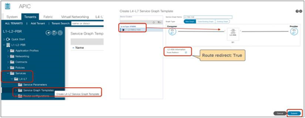
Create L4-L7 Devices (APIC Release 5.0) for L2 active/active deployment
Figure 160 provides an example of a L4-L7 device configured as a L1 device in active/active mode using APIC Release 5.0. Because this device is operating in L1 active/active mode, the VLAN encap configuration is at each concrete interface instead of each cluster interface and the physical domain configuration is at each cluster interface for port local scope. Please see “Port local scope configuration for L1 PBR active/active mode” for how to configure port local scope and physical domains.
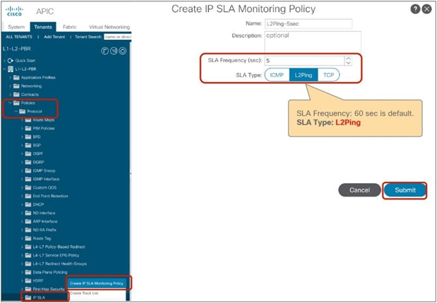
Create L4-L7 Devices (APIC Release 5.0) for L1 active/active deployment
Create the Service Graph Template (the same with L3 PBR)
This step is not specific to L1/L2 PBR. Create the Service Graph Template using the L4-L7 devices that you created. Route Redirect must be enabled to use PBR on the node (Figure 161).
The location is Tenant > L4-L7 Services > L4-L7 Service Graph Templates.
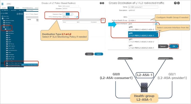
Create the Service Graph Template
Create IP SLA Monitoring Policy
Create IP SLA Monitoring Policy for tracking. You must select “L2Ping” for L1/L2 PBR. The default SLA frequency is 60 seconds. The IP SLA Monitoring policy will be referred in PBR policy in the next step.
The location is Tenant > Policies > Protocols > IP SLA
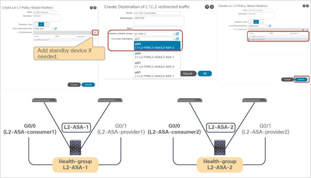
Create IP SLA Monitoring Policy (L2Ping)
Create PBR policy
Create PBR policy. You must select Destination Type L1 or L2 and configure the interface connected to the L1/L2 PBR device that is required to program static MAC endpoint for PBR. Unlike L3 PBR, IP information is not required and MAC information is optional. In this example, we are going to use G0/0 as the consumer connector and G0/1 as the provider connector, which are in the same Health Group.
The location is Tenant > Networking > Protocol Policies > Policy Based Redirect.
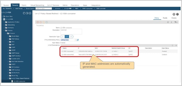
PBR policy for the consumer side
Prior to APIC Release 5.0, up to two L1/L2 destinations can be added in case of active/standby with tracking. More than two are not supported and will trigger a fault. Starting from APIC Release 5.0, more than two L1/L2 destinations can be added in case of active/active mode.
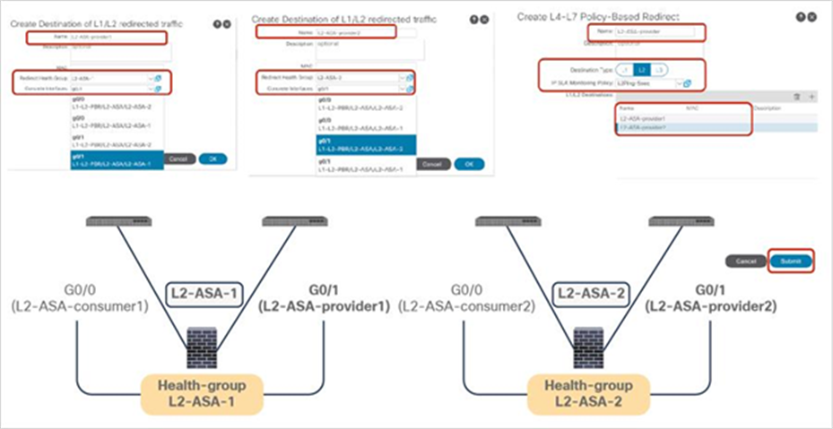
PBR policy for the consumer side (Add standby device.)
Note: Tracking is required for active/standby mode. As active/active is not supported prior to APIC Release 5.0, a threshold is not applicable. The down action is Deny when tracking is enabled. A down-action permit cannot be set in APIC Release 4.1 and 4.2. The down action option is supported after APIC Release 5.0.
IP and MAC are automatically generated. MAC is configurable, but IP is not. Though IP is not used for the L2 Ping header, it is the key for all destinations. The Cisco ACI fabric identifies a destination using the IP while publishing the tracking information.
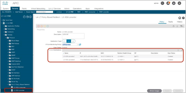
PBR policy for the consumer side
As two-arm mode is required for L1/L2 PBR, PBR policy for the other side is needed. Figure 166 shows an example configuration of PBR policy for the provider side.
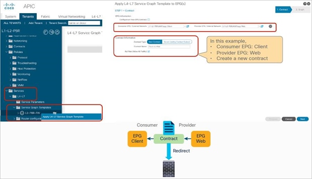
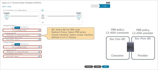
PBR policy for the provider side
Apply Service Graph Template to a contract
This step is not specific to L1/L2 PBR. Either using the Apply L4-L7 Service Graph Templates wizard or creating Device Selection Policy manually works. In this example, we are going to use the wizard. The wizard asks you to select the following information (Figure 167):
● Consumer EPG, provider EPG, and a contract subject to apply Service Graph
● BD, PBR policy, and the cluster interfaces for both the provider and consumer connectors of the PBR node
The location is Services > L4-L7 > Service Graph Templates.
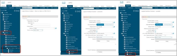
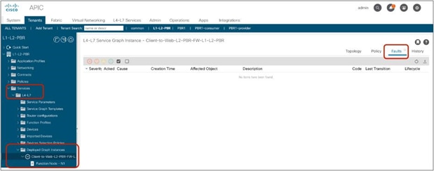
Apply Service Graph Templates
It creates a Device Selection Policy and associates the Service Graph to the contract. The location is Services > L4-L7 > Device Selection Policy.
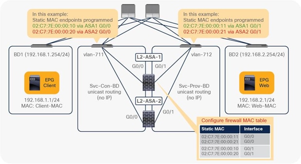
Device Selection Policy
If everything is configured properly, you should be able to see Deployed Graph Instance without any fault. The location is Services > L4-L7 > Deployed Graph Instance.
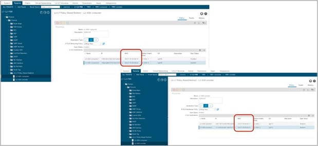
Deployed Graph Instance
Note: Zoning-rule is also updated on the provider and consumer leaf switches, which is explained in the later section.
Cisco Adaptive Security Appliance (ASA) configuration example
This section explains a configuration example for Cisco ASA. The considerations of L2 PBR with Cisco ASA are as follows:
● Configure Access Control List to permit Ethertype 0x0721 for L2 Ping, because Cisco ASA does not permit it by default.
● Configure PBR destination MAC addresses on the MAC address table, because Cisco ASA transparent mode performs destination MAC lookup.
● Disable MAC address learning on the Cisco ASA, because the source MAC address of L2 Ping is the same source MAC address as for the keepalives to the consumer and the provider connectors, which means the Cisco ASA observes the same source MAC from different interfaces, and it causes MAC address flapping on the Cisco ASA.
We are going to use the example illustrated in Figure 170.
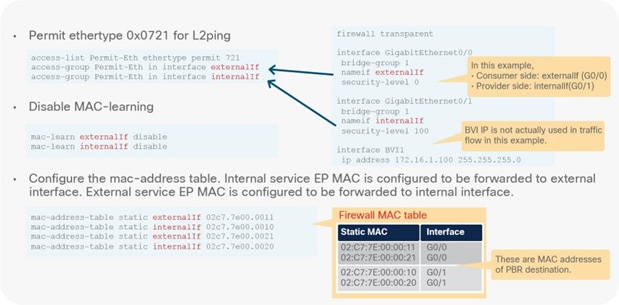
Topology example
If you prefer, you can specify the PBR destination MAC that is automatically generated by default. The location is Tenant > Networking > Protocol Policies > Policy Based Redirect.
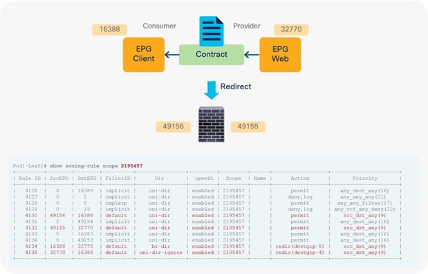
Specify PBR destination MAC addresses (optional)
Figure 172 shows a Cisco ASA configuration example. In this example, ASA external interface (consumer connector) is named “externalIf” and ASA internal interface (provider connector) is named “internalIf.”
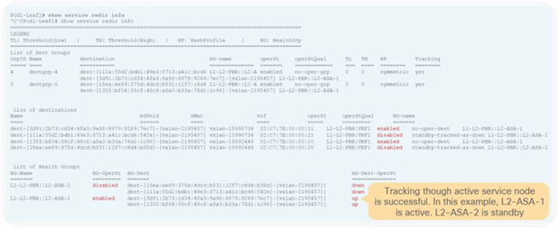
Cisco ASA configuration example
CLI output example for verification
This section explains CLI command on leaf switches to verify PBR and tracking.
The contract policy is programmed on the consumer and provider leaf nodes. Once Service Graph is deployed, zoning-rule on the VRF is updated the same as in L3 PBR.
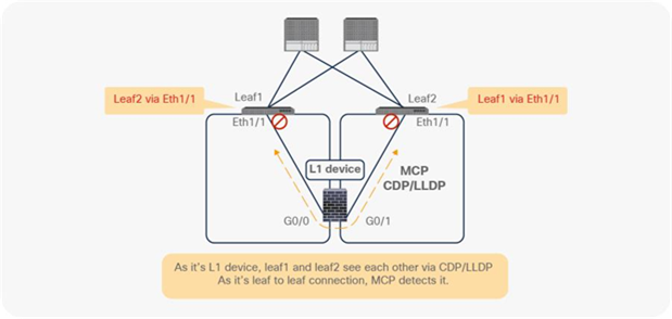
Zoning-rule on consumer/provider leaf nodes
Tracking through active service node should be successful. In this example, L2-ASA-1 is active and L2-ASA-2 is standby. The Cisco ACI fabric identifies a destination using the IP in PBR policy, which is automatically generated.
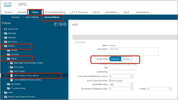
Tracking status on consumer/provider leaf nodes
These are troubleshooting tips:
● PBR node does not receive the traffic:
◦ Check zoning-rule on consumer and provider leaf switches to ensure you have redirect rule.
◦ Check if PBR policy is applied at consumer/provider leaf switches.
◦ Check if tracking status is up.
● Tracking is enabled but the status is down:
◦ Check if the PBR destination MAC is in the service leaf where the PBR node is connected.
◦ Check the PBR node configuration to ensure the device permits L2 Ping and try to capture packets.
● Traffic is not returning from the PBR node:
◦ Check the PBR node configuration to ensure the PBR node permits the traffic.
L1 device connectivity considerations
This section explains L1 device connectivity considerations.
Disable loop detection mechanism
ACI fabric has Loop detection mechanism. If L1 device between Leaf nodes carry Mis-Cabling Protocol (MCP) packet or CDP/LLDP packet, ACI fabric may detect loop, which will make ports out-of-service status. To avoid this, we may need to disable MCP or CDP/LLDP on ports connected to L1 device.
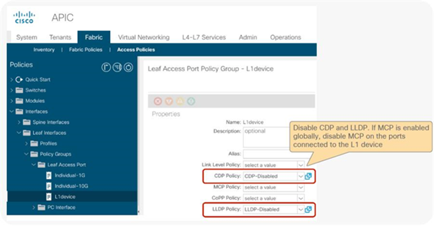
ACI Loop detection
MCP is disabled by default. If you enable MCP globally, you need to disable MCP on the interface policy group for the leaf interfaces connected to L1 device. The location of MCP global setting is Fabric > Access Policies > Policies > Global.
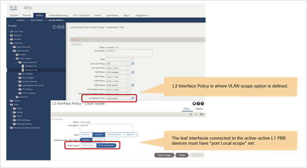
MCP configuration (Global)
CDP is disabled by default and LLDP is enabled by default. The interface policy group configuration location is Fabric > Access Policies > Interfaces > Leaf Interfaces > Policy Groups.
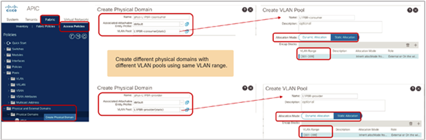
CDP/LLDP configuration (Interface policy group)
Port local scope configuration for L1 PBR active/active mode
For L1 PBR active/active mode, consumer and provider connectors must be in different physical domains for port local scope configuration. The interface policy group for the leaf interfaces connected to the L1 PBR devices must have “port Local scope” set in addition to disabling loop detection mechanism explained in the previous section.
The interface policy group configuration location is Fabric > Access Policies > Interfaces > Leaf Interfaces > Policy Groups.
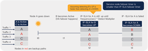
Port local scope configuration (L2 Interface policy)
To use port local scope, each cluster interface must be in different physical domain, thus two physical domains with different VLAN pools that have the same VLAN need to be configured. Though physical domains must be different, Attached Entity Profile (AEP) of the leaf interfaces can be same for both consumer and provider cluster interfaces as long as they are connected to different leaf. The physical domain configuration location is Fabric > Access Policies > Physical and External Domains.
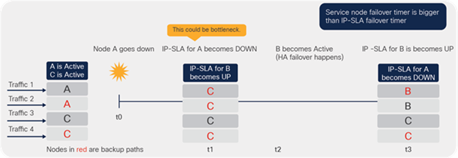
Create two physical domains with different VLAN pools
Multiple active/standby HA pairs design consideration
If multiple active-standby pairs are used, service node failover timer should be always smaller than IP-SLA failover timer.
Figure 180 illustrates example1 where service node failover timer is smaller than IP-SLA failover timer. HA pair1 has active destination A and standby destination B, and HA pair2 has active destination C and standby destination D. If A goes down (t0), service node failover happens first and B becomes active (t1). After that, tracking for B becomes UP(t2) and tracking for A becomes DOWN(t3).
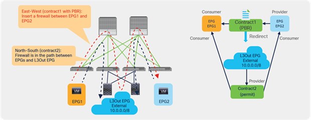
Example1: service node failover timer is smaller than IP-SLA failover timer (recommended)
Figure 181 illustrates example2 where service node failover timer is bigger than IP-SLA failover timer. If A goes down(t0), tracking for A becomes DOWN first (t1) because service node failover timer is bigger than IP-SLA failover timer. After that, service node failover happens and B becomes active (t2). Then, finally tracking for B becomes UP(t3). Obviously example1 is better than example2 because of the status of t1 in example2 could cause bottle neck and example2 would have longer (t3-t0) than example1.
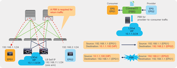
Example2: service node failover timer is bigger than IP-SLA failover timer (NOT recommended)
Starting with APIC Release 5.2, L3 PBR destinations can be in an L3Out instead of an L3 bridge domain, which provides more flexible design options. This section explains the use case examples, how to configure, how forwarding works, and design considerations.
Use case examples
The first example in Figure 182 shows a use case of north-south and east-west firewall insertion. Imagine you have firewalls connected via an L3Out, which is for north-south (L3Out-EPG) traffic inspection. Then you want to use the same firewall internal interfaces for east-west (EPG-EPG) traffic inspection. Prior to APIC Release 5.2, this was not possible because the firewall internal interfaces were connected via an L3Out where PBR could not be enabled.
The requirement can now be achieved by performing the following configurations:
● Enable PBR on the contract (Contract1 in this example) between EPGs for east-to-west firewall insertion. The PBR destination is connected via the L3Out.
● Configure the contract (Contract2 in the example) without PBR between the L3Out EPG and the other EPGs for north-to-south firewall insertion.
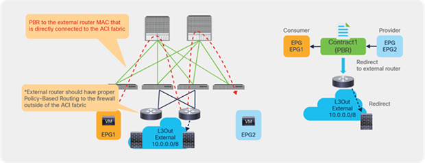
Use case example 1: North-south perimeter firewall insertion
The second example in Figure 183 shows a use case of load balancer insertion. Imagine that you have load balancers connected via an L3Out because the VIP address is not in the bridge domain subnet range where the load balancer interface IP address resides. At the same time, you want to enable PBR for the return traffic (EPG2-to-EPG1 in this example) using the same load balancer interface to avoid enabling NAT on the load balancer. Prior to APIC Release 5.2, this was not possible unless you had a separate load balancer internal interface in an L3 bridge domain to enable PBR.
The requirement can now be achieved by enabling PBR for the return traffic as follows:
● Do not configure PBR for consumer-to-provider traffic: PBR should not be enabled as the traffic is destined to the VIP owned by the load balancer. You need to configure the ACI fabric to route to the VIP using the L3Out toward the load balancer.
● Configure PBR for provider-to-consumer traffic: PBR is enabled to make return traffic back to the load balancer. The PBR destination is connected via the L3Out.
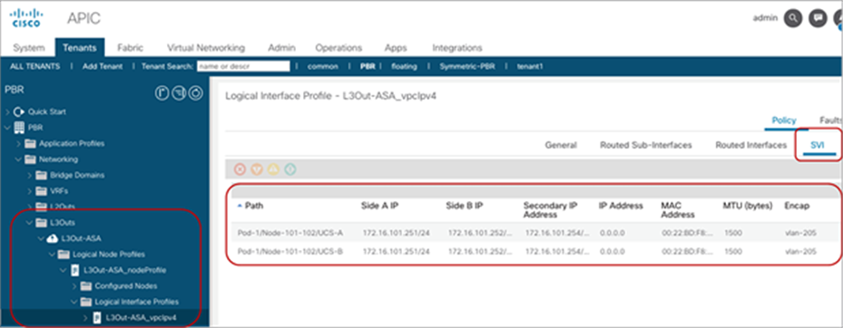
Use case example 2: Load balancer insertion
The third example in Figure 184 shows a use case of a service device that is not directly connected to the ACI fabric. Starting from APIC Release 5.2, PBR destinations can be behind external routers connected via an L3Out.
Design considerations:
● You need to configure the PBR redirect policy with the MAC address of the external router and the IP address of the service node behind the external routers. ACI rewrites the destination MAC of the traffic, but it doesn't rewrite the IP address. The reason to enter the IP address of the PBR destination is because ACI uses this information for IP-SLA tracking.
● The result of the previous configuration is the ability for ACI to redirect traffic to an external router. The destination IP address of the redirected traffic is the IP of the server in EPG2 and Policy Based Redirect doesn't rewrite this IP address. An external router would then just forward this traffic based on the destination IP: for the traffic to go via the service device attached to the router you need to configure Policy Based Routing on the external router.
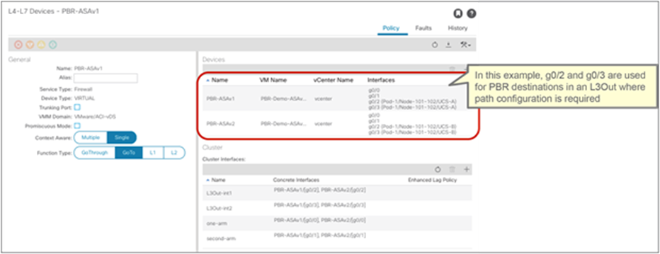
Use case example 3: Service device not directly connected to the ACI fabric
Configuration
Although the configuration flow is the same as the L3 PBR service graph that uses PBR destinations in an L3 bridge domain, there are a couple of additional configuration requirements on the L3Out, L4-L7 Device, and tracking configurations. This section mainly covers the PBR destinations in an L3Out specific configuration consideration. For general PBR configurations, check the previous section.
This section doesn’t cover how to create a tenant, VRF, consumer, and provider BD and EPG. The assumption is that consumer EPGs, provider EPGs, and BDs already exist and are already configured.
Configuration steps:
1. Create an L3Out for PBR destinations.
2. Create an L4-L7 Device.
3. Create a Service Graph Template (the same with L3 PBR that uses PBR destination in an L3Out).
4. Configure an IP SLA Monitoring policy. (IP-SLA Tracking is mandatory for the PBR destination in an L3Out.)
5. Create a PBR policy.
6. Apply the Service Graph Template to a contract.
The PBR destination in an L3Out has the following configuration requirements:
● The L3Out for the PBR destination must be in either the consumer or provider VRF.
● L3Out with SVI, routed sub-interface, or routed interface is supported. (Infra L3Out, GOLF L3Out, SDA L3Out, or L3Out using floating SVI for PBR destination is not supported.)
● IP SLA tracking is mandatory for the PBR destination in an L3Out for better convergence.
● The L3Out EPG with 0.0.0.0/0 or 0::0 subnet can’t be used for the L3Out EPG for PBR destinations.*
Also check the requirements and design considerations section for details.
Create an L3Out for PBR destinations
The location to create an L3Out for PBR destination is the same as any L3Out: the location is Tenant > Networking > L3Outs. Although the example in Figure 185 uses an SVI interface, you can also configure routed interface. Floating SVI has not been integrated yet for the use with PBR destinations.
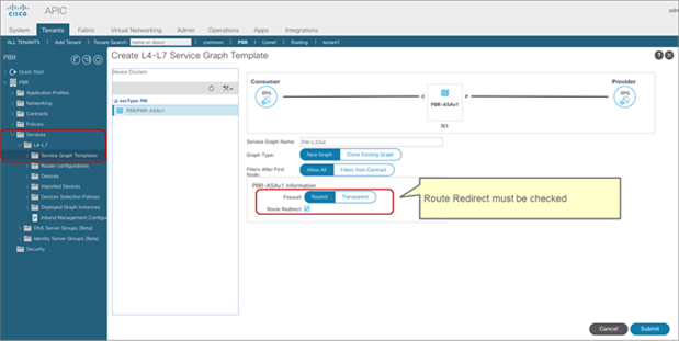
Create an L3Out
Create an L4-L7 Device
The location to create an L4 – L7 device is Tenant > Services > L4-L7 > Devices. Even if the L4-L7 device is in a VMM domain, the path configuration in the concrete device interface is mandatory for PBR destinations in an L3Out.
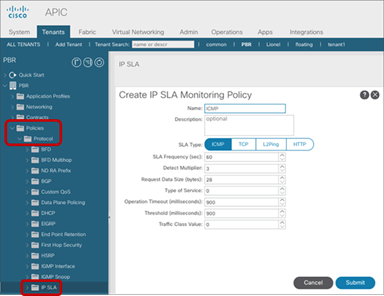
Create an L4-L7 Device for a PBR destination in an L3Out
Note: During service graph rendering, the APIC checks if the L3Out logical interfaces for PBR are being matched with the concrete interfaces in the L4-L7 device. (Path configuration in Figure 185 and 186 must be matched.) If it doesn’t match (for example, if interface path configurations are different), the APIC raises a fault and the service graph rendering fails.
Create a Service Graph Template
This configuration step is the same as the service graph, which uses PBR destinations in an L3 bridge domain. The location is Tenant > Services > L4-L7 > Service Graph Templates.
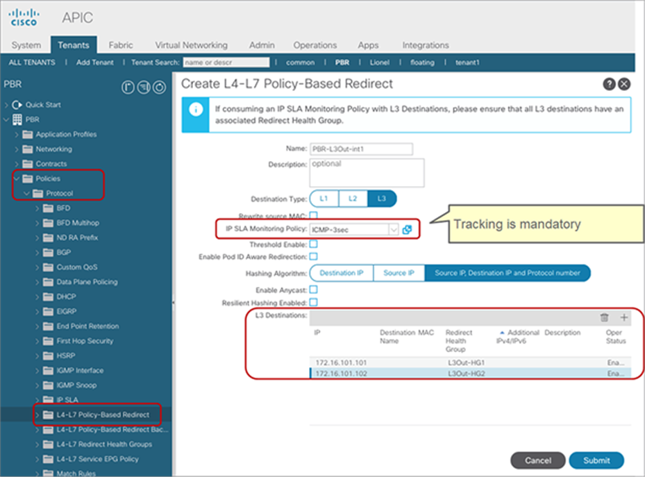
Create a Service Graph Template
Configure an IP SLA Monitoring policy
The configuration of IP SLA monitoring is mandatory for a PBR destination in an L3Out. The configuration step is the same as the service graph that uses PBR destinations in an L3 bridge domain. The location is Tenant > Policies > Protocol > IP SLA > IP SLA Monitoring Policies.
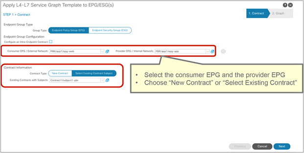
Create an IP SLA Monitoring Policy
Create a PBR policy
Create a PBR policy to provide the APIC with the IP addresses and MAC addresses for the PBR destinations. Tracking is mandatory for a PBR destination in an L3Out. To enable tracking, Redirect Health Groups need to be configured. The location of the configuration is Tenant > Policies > Protocol > L4-L7 Policy-Based Redirect.
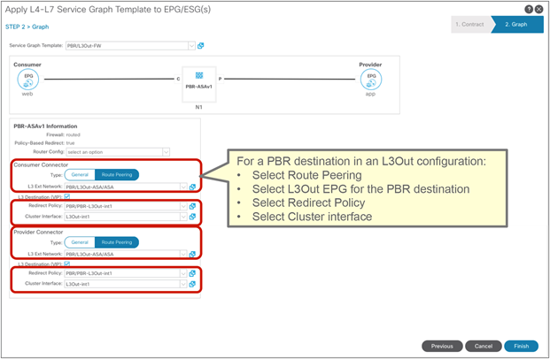
Create a PBR policy
Apply the Service Graph Template to a contract
Apply the service graph template to a contract by either using the Apply L4-L7 Service Graph Templates wizard or by creating a Device Selection Policy manually. In this example, we are going to use the wizard. The wizard asks you to select the following information (Figure 190):
● Consumer EPG, provider EPG, and a contract subject to apply the service graph
● BD or L3Out, PBR policy, and the cluster interfaces for both the provider and consumer connectors of the PBR node
The location is Tenant > Services > L4-L7 > Service Graph Templates.
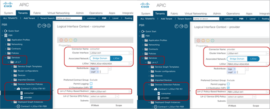
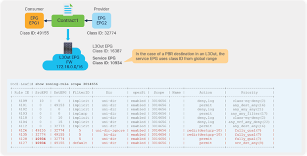
Apply Service Graph Template
Once you have completed the steps in applying in the Service Graph Template Wizard, a Device Selection Policy is created and the service graph is associated to the contract subject. The location of Device Selection Policy is Tenant > Services > L4-L7 > Device Selection Policy.
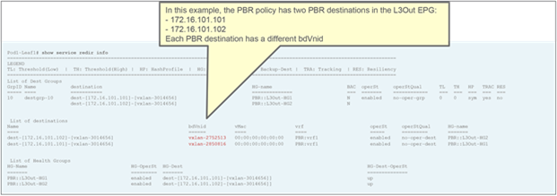
Device Selection Policy
If everything is configured properly, you should be able to see a Deployed Graph Instance without any fault. The location is Tenant > Services > L4-L7 > Deployed Graph Instance.
Verification
Once the service graph is deployed, zoning-rules are updated.
The way ACI programs zoning-rules for PBR with a PBR destination in an L3Out is very similar to a regular PBR deployment, with some minor differences:
● The hidden service EPG uses the class ID from the global range (16-16384) even when there is an intra-VRF contract (Figure 192).
● A unique bdVnid (VNID: VXLAN Instance ID) is allocated for each PBR destination (L4–L7 device) even if the L4–L7 devices are connected via the same L3Out (Figure 193). How this VNID information is used for forwarding will be explained in the next section.
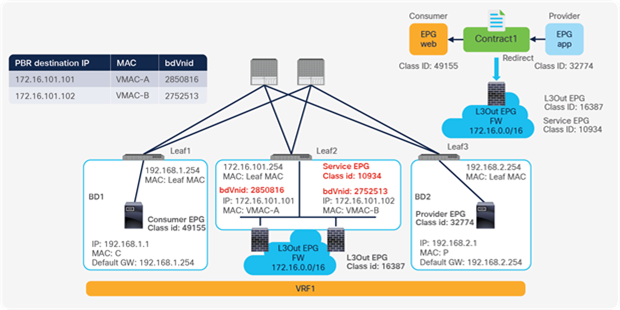
Zoning-rule on consumer/provider leaf nodes
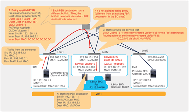
Status of PBR destinations
How forwarding works
Based on the configuration example in the previous section, this section explains how forwarding works. Figure 194 shows an example in which web EPG is a consumer EPG and the app EPG is a provider EPG with a contract with the service graph that uses PBR destinations in an L3Out. Although this example uses a one-arm firewall design and an intra-VRF contract, two-arm service node designs and inter-VRF contracts are also possible. In this example, the PBR policy is applied on the ingress leaf for both directions, however, where the policy is applied may differ depending on the contract configuration and endpoint learning status.
As figures 185 and 186 in the previous section show, a hidden service EPG is created internally and a unique bdVNid is allocated for each PBR destination.
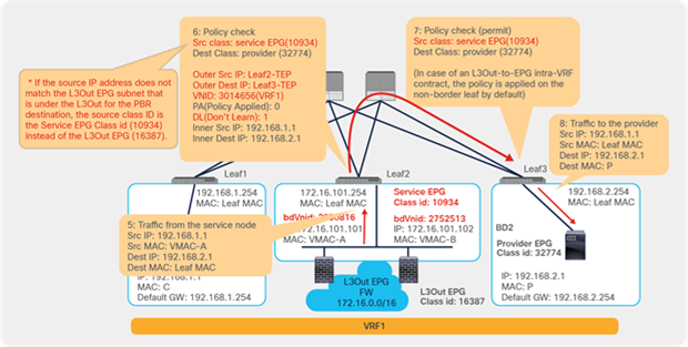
Topology example: PBR destination in an L3Out
The consumer endpoint generates traffic destined for the provider endpoint. If Leaf1 has already learned the destination endpoint, Leaf1 can resolve the source and destination EPG class IDs, so PBR is performed on Leaf1. Here, the destination VNID in the VXLAN header is set to a bdVNid allocated for a PBR destination, which indicates which PBR destination is selected. The destination TEP is the service leaf node TEP. Unlike PBR destinations in an L3 bridge domain, redirect traffic destined to a PBR destination is not sent to the L2 spine proxy. This is because the consumer/provider leaf can get the route to the PBR destination subnet from the routing table (in this case, 172.16.101.0/24, which is the L3Out logical interface subnet advertised via BGP from Leaf2) and send the packet directly to the service leaf node TEP.
For each bdVNid, a corresponding internal VRF that is different from the consumer or provider VRF is deployed on the service leaf. The routing table on the internal VRF contains a default route with the PBR destination MAC address as the next-hop: 0.0.0.0/0 via VMAC-A in this example. Although VMAC-A is not an endpoint in the internal VRF, the service leaf forwarding table can forward the traffic to VMAC-A in VRF1. Thus, the traffic arriving on the service leaf that has a destination VNID for a PBR destination is forwarded to the corresponding PBR destination.
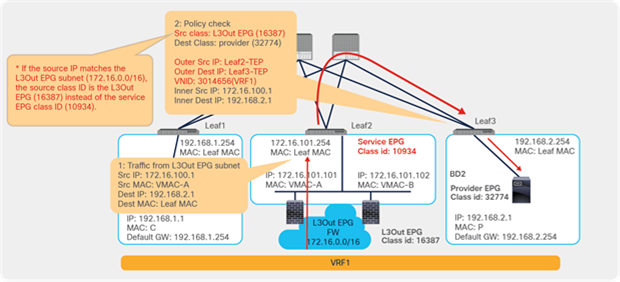
Traffic flow example: Consumer-to-provider traffic is redirected to the PBR node
Note: Internal VRFs are deployed only on the service leaf nodes. VRF scalability on the service leaf nodes need to be taken into consideration. For example, if you have 10 PBR destinations in a PBR policy and all are connected to the same service leaf nodes, 10 internal VRFs are deployed on the service leaf nodes. (One internal VRF is created for each PBR destination).
Then, traffic goes through the PBR node and returns to the ACI fabric. Although it arrives at the L3Out logical interface, If the source IP address matches the consumer or the provider BD subnet, or if it does not match the L3Out EPG subnet that is under the L3Out for the PBR destination, it is classified to the hidden service EPG (class ID 10934 in this example) instead of the L3Out EPG used for the PBR destination (class ID 16387 in this example). In this way, the ACI fabric can distinguish the traffic coming back after PBR from the traffic arriving on the L3Out logical interface without PBR. In this example, traffic from the hidden service EPG to the provider EPG (10934-to-32774) is permitted because of the zoning-rule created through the service graph deployment (Figure 192).

Traffic flow example: PBR node to the provider
If traffic arrives at the ACI L3Out logical interface without PBR, as shown in Figure 197, the source IP address matches the L3Out EPG subnet. It is classified to the L3Out EPG (class id 16387 in this example) instead of the hidden service EPG. If there is no permit rule for 16387-to-32774, traffic will be dropped. That rule is not part of the zoning-rules created through the service graph deployment (Figure 192).
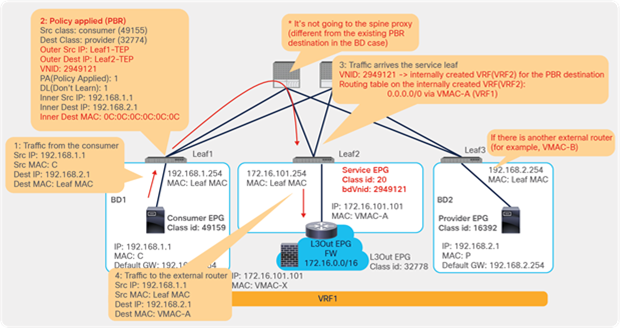
Traffic flow example: Traffic coming from an L3Out without PBR
Following is a summary of forwarding behaviors specific to PBR destinations in an L3Out:
● A hidden service EPG is created that uses a class ID from the global range (16-16384), even if the service graph is applied to an intra-VRF contract.
● A unique bdVnid (VNID: VXLAN Instance ID) is allocated for each PBR destination.
● For each bdVNid, an internal VRF is created on the service leaf.
● Spine-proxy is not used when leaf nodes apply PBR policy, even in the case of inter-VRF contracts.
This section explains the following design consideration examples:
● PBR destination IPs behind external routers
● Two-arm design
● Load balancer keepalive
For general considerations related to a PBR destination in an L3Out, refer the section, “Requirements and design considerations”.
PBR destination IPs behind external routers
If the PBR destination IP is behind external routers, the external routers that are in between the ACI leaf nodes and the service nodes must have a proper Policy Based Routing configuration to manage the traffic because the APIC doesn't configure networks outside of the ACI fabric.
Figure 198 illustrates an example topology of one external router and one PBR destination IP. In this case, the PBR destination IP is the service node IP, which is used for IP-SLA tracking. The PBR destination MAC is the MAC of the external router directly connected to the ACI fabric, which is used for the redirection.
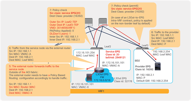
Traffic flow example: PBR destination IP is behind external routers
As illustrated in Figure 199, the redirection mechanism is the same with the example outlined in Figure 195.
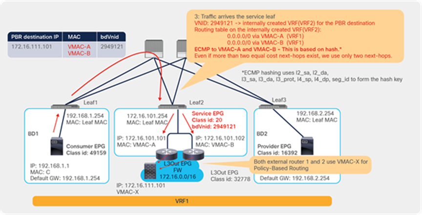
Traffic flow example: Consumer-to-provider traffic is redirected to the external router
After the redirection, the external router needs to forward traffic to the service node accordingly (step 5 in this example), which is outside of the ACI fabric. Also, the external router needs to send traffic back to the ACI fabric after the service node sends traffic back to the external router (step 6 in this example).
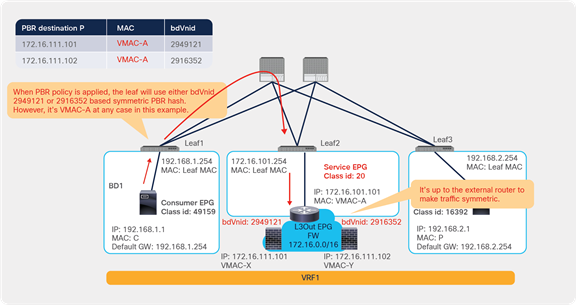
Traffic flow example: PBR node to the provider
Figure 201 illustrates an example topology of two external routers and one PBR destination IP. In this case, the internal VRF on the service leaf nodes have two ECMP default routes. Traffic will be forwarded to either one of the external routers (VMAC-A or VMAC-B in this example) based on hash. Even if there are more than two external routers, up to two next-hops are used in the default route on the internal VRF.
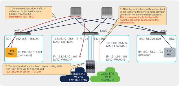
Traffic flow example: Multiple external routers
Figure 202 illustrates an example topology of one external router and two PBR destination IPs. In this case, even though a unique bdVnid is allocated to each PBR destination IP, the PBR destination MAC is the same external router MAC. Thus, the load balancing behavior relies on the external router’s behavior. The external router must ensure the incoming and return traffic go to the same service node to keep traffic symmetric.
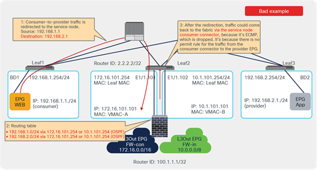
Traffic flow example: One external router and two PBR destinations
Two-arm design
If the service node is connected to the ACI fabric using two-arm designs, the service node must have a proper routing table. Figure 203 illustrates an example that works and Figure 204 illustrates an example that doesn’t work.
The traffic destined to the provider should be sent out via the provider connector of the service device and the traffic destined to the consumer should be sent out via the consumer connector of the service device. Otherwise, traffic could be dropped because there is no zoning-rule to permit traffic from the consumer connector to the provider and the traffic from the provider connector to the consumer.
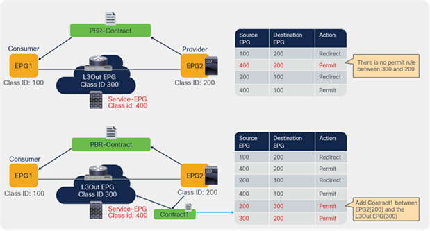
Valid two-arm design example
If two L3Outs with OSPF or EIGRP in the same VRF on the same leaf are connected to the service device, a single OSPF or EIGRP session with two adjacencies is formed with the service device because the ACI fabric can’t have two router IDs in the same VRF on the same leaf. It could cause equal-cost multi-path (ECMP) routing on the service leaf, which causes traffic to drop. Possible design options include:
● Use of BGP or a static route instead of OSPF or EIGRP
● Use of a separate VRF
● Use of a different service leaf node for each L3Out
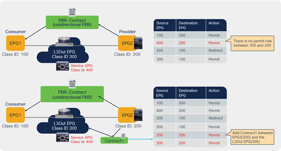
Example of a two-arm design that doesn’t work
Load balancer keepalive considerations
There are designs where the L4–L7 device (that is also a PBR destination) needs to send and receive traffic directly to endpoints in the fabric. An example of this is a deployment of a load balancer, where the load balancer needs to send keepalives to verify the reachability and liveliness of the servers to which it distributes the traffic. For these designs, you need to understand how to allow traffic between the L4-L7 device and regular EPGs, and in the case of an L4–L7 device connected to an L3Out, also between the L3Out EPG (where the L4-L7 device is connected) and regular EPGs.
By default, bi-directional permit rules between a consumer/provider EPG and a hidden service EPG are not created. Bi-directional permit rules might be required if the direct communication to the PBR destination is required (for example, to permit load balancer keepalive traffic). An example with a PBR destination in an L3 bridge domain is described in the section, “Direct Connect option”. This section explains examples with a PBR destination in an L3Out.
Table 21 illustrates the different possible combinations of service EPGs, L3Out EPGs, and regular EPGs that are relevant to allow the communication with a PBR destination. The entries under EPG1 and EPG2 represent the possible combinations of EPG types for the provider and consumer. Either EPG can be the provider or the consumer. If EPG1 is the provider, then EPG2 is the consumer. Similarly, if EPG2 is the provider, then EPG1 is the consumer. The point of this table is that for a PBR design with the L4–L7 device connected to a L3 bridge domain, you should consider row 1 for a PBR design with the L4–L7 device connected as a PBR destination to a L3Out. The relevant row is row 2; and row 3 is for a multinode service graph with one L4 –L7 device connected as a PBR destination to an L3Out and another L4–L7 device connected as a PBR destination to an L3 bridge domain.
Table 21. Options to allow communication to a L4 L7 device used as a PBR destination
| EPG1 |
EPG2 |
Comments |
| Service EPG in an L3 bridge domain |
Consumer/provider EPG, Consumer/provider L3Out EPG or Service EPG in an L3 bridge domain (multi-node service graph) |
Supported You need to enable “Direct Connect” |
| L3Out EPG used for a PBR destination in an L3Out (not a hidden service EPG) |
EPG or L3Out EPG |
Supported The user can create a contract between the L3Out EPG used for the PBR destination in the L3Out and EPG/L3Out EPG. |
| L3Out EPG used for a PBR destination in an L3Out (not a hidden service EPG) |
Service EPG in an L3 bridge domain |
Not possible as of ACI Release 5.2 |
This section explains the second and third use cases outlined in Table 21. The first use case was explained in the section, “Direct Connect option”.
Figure 205 illustrates a firewall insertion example of the second use case in Table 21. A contract with PBR to insert a firewall is configured between EPG1 and EPG2. If endpoints in EPG2 need to directly communicate with the firewall IP that is in the L3Out EPG subnet, the L3Out EPG (not the hidden service EPG) to the EPG2 contract needs to be manually configured because bi-directional permit rules between them are not created as part of the service graph deployment, even if the permit rule for the traffic from the hidden service EPG to the provider EPG (400-to-200 in this example) is created.
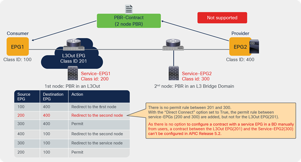
Permit traffic between the provider EPG and the L3Out EPG used for PBR destination
Figure 206 illustrates a load balancer insertion example of the second use case in Table 21. A contract with a unidirectional PBR to insert a load balancer is configured between EPG1 and EPG2. The assumption is that the load balancer IP that is used for the keepalive traffic from the load balancer to the provider endpoints is part of the L3Out EPG subnet.
The permit rule for the traffic from the hidden service EPG to the provider EPG is created as part of the service graph deployment, but there are no bi-directional permit rules between the L3Out EPG and the provider EPG (300-to-200 and 200-to-300 in this example). The L3Out EPG (not the hidden service EPG) to the EPG2 contract needs to be manually configured to permit keepalive traffic between the load balancer and the provider endpoints.

Permit load balancer keepalive traffic between the provider EPG and the L3Out EPG used for PBR destination
Figure 207 illustrates am example of the third use case in Table 21. A contract with a multi-node PBR is configured between EPG1 and EPG2. Bi-directional permit rules between the first node IP in the L3Out EPG subnet and the second node IP in the L3 bridge domain cannot be added as of APIC Release 5.2(1g). This is because there is no option to manually add a contract with a service EPG in an L3 bridge domain. Thus, node-to-node connectors in a service graph can’t be a mix of a PBR destination in an L3Out and a PBR destination in an L3 bridge domain if direct communication between nodes is required. A workaround is the use of a contract with vzAny that includes the service EPGs too.
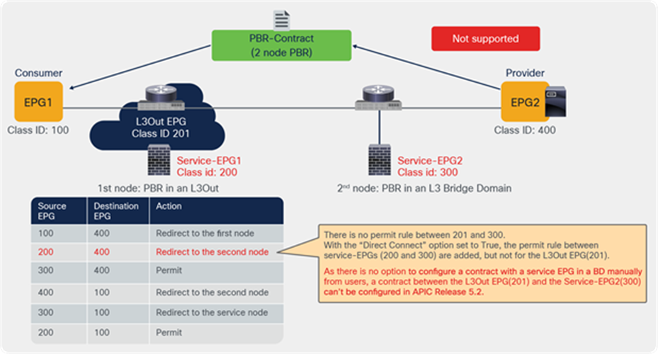
Multi-node service graph consideration: communication between nodes
Appendix: PBR-related feature enhancement history
PBR-related feature enhancements and when they are introduced are listed in Table 22.
Table 22. PBR-related features
| ACI Release |
Feature |
| 2.0 |
PBR |
| 2.1 |
Trunk port-group |
| 2.2(3j) |
PBR node Tracking (ICMP. Down action permit only) |
| 3.1 |
PBR node Tracking (ICMP and TCP. Down action permit and deny) PBR node and consumer and provider EPGs in the same subnet Location-based PBR for Cisco ACI Multi-Pod design PBR for contract between uSeg EPGs except uSeg EPG in vDS VMM domain |
| 3.2 |
Multi-site + Service Graph with PBR (1 node Service Graph) Service Graph with PBR for contract between uSeg EPGs in vDS VMM domain. |
| 4.0 |
Multi-site + Service Graph with PBR (2 node Service Graph) PBR with intra EPG contract, Copy with intra EPG contract Preferred group for service EPG |
| 4.1 |
|
| 4.1.2 |
|
| 4.2 |
|
| 4.2(3) |
|
| 4.2(5) |
|
| 5.0 |
|
| 5.1(3) |
|
| 5.2(1) |
VMware enhanced LACP support for virtual L4-L7 devices Intra-EPG contract (permit, deny, and PBR) for an L3Out EPG L3 PBR without MAC configuration (dynamic PBR destination MAC detection) |
| 5.2(4) |
|
| 6.0 |
Note: These features require Cisco Nexus 9300-EX and -FX platform leaf switches onward, except for PBR in Cisco ACI Release 2.0.
● Cisco ACI Multi-Site and Service Node Integration White Paper