Cisco ACI Multi-Pod and Service Node Integration White Paper
Available Languages
Bias-Free Language
The documentation set for this product strives to use bias-free language. For the purposes of this documentation set, bias-free is defined as language that does not imply discrimination based on age, disability, gender, racial identity, ethnic identity, sexual orientation, socioeconomic status, and intersectionality. Exceptions may be present in the documentation due to language that is hardcoded in the user interfaces of the product software, language used based on RFP documentation, or language that is used by a referenced third-party product. Learn more about how Cisco is using Inclusive Language.
This document describes deployment considerations for integrating Layer 4 through Layer 7 (L4–L7) network services in a Cisco® Application Centric Infrastructure (Cisco ACI®) Multi-Pod fabric. The document specifically focuses on stateful firewalls. The following use cases are considered:
● Layer 2 and Layer 3 firewall design
● North-south and east-west firewall design
● Active-standby service node pair connected to separate pods
● Active-active service node cluster stretched across separate pods
● Independent active-standby service node pair in each pod
To best understand the design presented in this document, you should have basic knowledge about the Cisco ACI Multi-Pod solution, the deployment of L3Out connectivity between the Multi-Pod fabric and the external Layer 3 domain, service graphs with Policy-Based Redirect (PBR), and Cisco Adaptive Security Appliance (ASA) clusters and how they work. For more information, see the Cisco ACI white papers and Cisco ASA documents available at Cisco.com:
Cisco ACI Multi-Pod and WAN integration
Starting from release 2.0 of the Cisco ACI software, Cisco offers the Cisco ACI Multi-Pod solution, which allows you to interconnect multiple Cisco ACI sites, or pods, under the control of the same Cisco Application Policy Infrastructure Controller (APIC) cluster. This solution provides an operationally simple way to interconnect Cisco ACI networks that may be either physically co-located or geographically dispersed.
For more information about the Cisco Multi-Pod fabric, see the following white paper: https://www.cisco.com/c/en/us/solutions/collateral/data-center-virtualization/application-centric-infrastructure/white-paper-c11-737855.html?cachemode=refresh
At the same time, the applications hosted within the Cisco ACI fabric must be accessible from the external routed network (whether a Metropolitan Area Network [MAN], a WAN, or the Internet). This access normally is achieved by creating logical connections, called Layer 3 outside (L3Out) connections, between a pair of Cisco ACI border leaf nodes and external routers. Starting from release 2.0, Cisco ACI offers a new deployment model to interconnect a Cisco ACI fabric to external routed domains. This new model offers enhanced scalability, operational simplicity, and automation. This deployment model is called Layer 3 EVPN services over fabric WAN, but it is commonly referred to as GOLF.
For more information, see https://www.cisco.com/c/en/us/solutions/collateral/data-center-virtualization/application-centric-infrastructure/white-paper-c11-736899.html
For more information, see the Cisco ACI service-graph-design white paper at https://www.cisco.com/c/en/us/solutions/collateral/data-center-virtualization/application-centric-infrastructure/white-paper-c11-734298.html
The service graph functionality can then be enhanced by associating to it one or more Policy-Based Redirects (PBRs). For more detailed information on PBR, see the white paper at
Cisco Adaptive Security Appliance and Firepower Next-Generation Firewalls high availability
Cisco Adaptive Security Appliance (ASA) and Cisco Firepower® Next-Generation Firewalls (NGFW) clustering allows you to group multiple ASA nodes together as a single logical device to provide high availability and scalability. The two main clustering options discussed in this paper are active/standby and active/active. In both cases, the firewall cluster looks like a single logical device (a single MAC/IP address) to the network.
For more information, see the discussion of Cisco ASA clusters in the Cisco ASA configuration guide at https://www.cisco.com/c/en/us/td/docs/security/asa/asa97/configuration/general/asa-97-general-config/ha-cluster.html
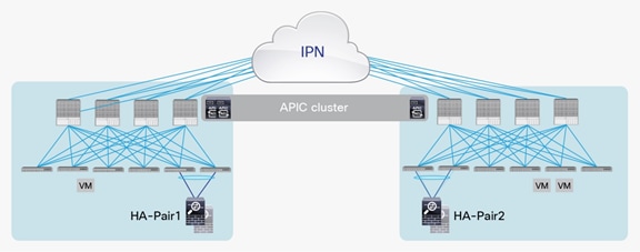
As of Cisco ACI Release 3.2(4d), the deployment options described here are available for integrating service nodes with Cisco ACI Multi-Pod fabrics (Figure 1).
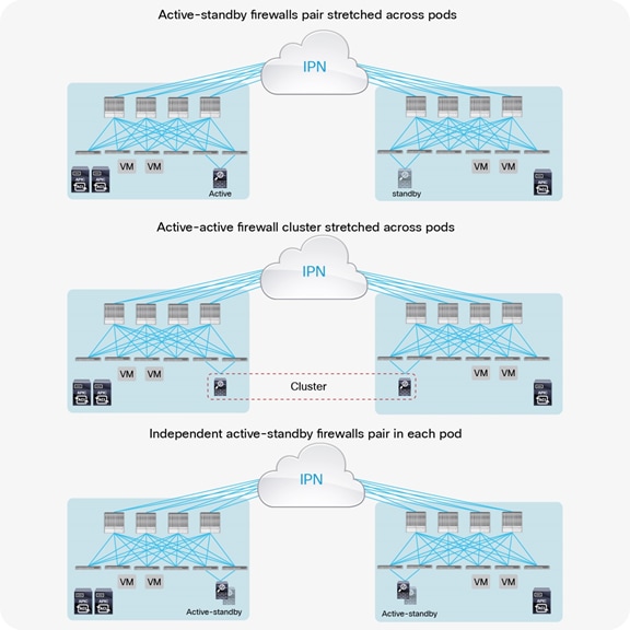
Network services deployment options with Cisco ACI Multi-Pod solution
● Active-standby firewalls pair stretched across pods: This model can be applied to both north-south and east-west traffic flows. This fail-safe model does not allow the creation of an asymmetric traffic path that could lead to communication drops. At the same time, because of the existence of a single active service node connected to the Multi-Pod fabric, this option has certain traffic-path inefficiencies, because by design some traffic flows will hair-pin across the Interpod Network (IPN). Therefore, you should be sure to properly dimension the bandwidth available across pods and consider the possible latency impact on application components connected to separate pods.
The active-standby model is supported with service nodes deployed in transparent or routed mode with independent L3Out connectivity of the external Layer 3 domain. Both the traditional border leaf nodes and the GOLF router options are supported for L3Out connectivity.
● Active-active firewall cluster stretched across pods: beginning with Cisco ACI Release 3.2(4d), an active/active firewall cluster can be stretched across pods. When deploying Cisco ASA or Cisco Firepower firewall appliances, this deployment model takes the name of “split spanned EtherChannel” and ensures that all the nodes of the cluster “own” the same MAC/IP values so that the stretched firewall cluster appears as a single logical entity to the ACI Multi-Pod fabric. This deployment model removes any concern about the possible creation of asymmetric traffic paths for both east-west and north-south traffic flows, as traffic will be dynamically redirected to the specific firewall node owning the connection state for that specific traffic flow.
● Independent active-standby firewalls pair in each pod: This model mandates that symmetric traffic flows through the service nodes be maintained because the connection state is not synchronized between independent nodes. This requirement can be achieved with the following approaches:
You can deploy symmetric Policy-Based Redirect (PBR) for both north-south and east-west security policy enforcement. This approach is the recommended solution. It consists of defining a PBR policy that specifies multiple active service nodes. The Cisco Nexus® 9000 Series Switches (EX platform or newer), used as leaf nodes, would then apply the symmetric PBR policy, selecting one of the available nodes for the two directions of each given traffic flow (based on hashing).
The use of PBR mandates that the service nodes be deployed in routed mode only prior to Cisco ACI Release 5.0. Starting from Cisco ACI Release 5.0, the service nodes can be deployed in inline/transparent mode that is also called L1/L2 mode. This model can integrate with L3Out connectivity with traditional border leaf nodes or GOLF nodes for external Layer 3 connectivity.
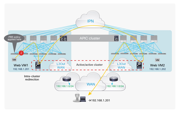
If deployment of symmetric PBR is not possible, in the specific case of perimeter firewall deployments (only for north-south traffic flows), it is necessary to keep ingress and egress traffic flows optimized and symmetric. This can be achieved by enabling granular host-route advertisement toward the external Layer 3 domain to ensure that ingress traffic paths are always delivered in the “right pod” where the destination endpoint is connected.
Host-route advertisement is supported on regular L3Outs deployed on border leaf nodes from Cisco ACI Release 4.0 onwards. This allows connecting firewall nodes deployed in routed mode between the border leaf nodes and the external WAN edge routers. Prior to Cisco ACI software release 4.0, host-route advertisement is only supported on GOLF L3Outs; firewall nodes can be deployed in routed mode and physically connected north of the GOLF routers to apply policy on the traffic when it is not encapsulated by virtual extensible LAN (VXLAN).
Note: The best-practice recommendation (and most common deployment model) is to configure L3Outs on border leaf nodes, rather than opting for the GOLF approach.
The options and considerations are summarized in Table 1.
Table 1. Service node integration modes for Cisco ACI Multi-Pod fabric
|
|
Active-standby firewall nodes stretched across Pods (north-south) |
Active-standby firewall nodes stretched across Pods (east-west) |
Active-active firewall cluster stretched across Pods north-south or east-west) |
Active-standby firewall nodes per Pod (north-south) |
Active-standby firewall nodes per Pod (east-west) |
| Transparent mode (L1/L2 device) |
Yes |
Yes |
No |
Yes (from Cisco ACI Release 5.0 with symmetric PBR) |
Yes (from Cisco ACI Release 5.0 with symmetric PBR) |
| Routed mode (L3 device) |
Yes |
Yes |
Yes (from Cisco ACI Release 3.2(4d)) with PBR |
Yes (symmetric PBR or requirement for ingress/egress traffic symmetry) |
Yes (symmetric PBR only) |
Service node integration with Cisco ACI Multi-Pod solution
Several deployment models are available for integrating network services in a Cisco ACI Multi-Pod fabric. To determine the best options to choose, you should consider all the specific requirements and characteristics of the design:
● Service node location and function
● North-south service node (or perimeter service node), for controlling communications between the data center and the external Layer 3 network domain.
● East-west service node, for applying policies for traffic flows within the data center. For the east-west enforcement, there are two cases to consider: in the first one, the firewall is used to apply policies between EndPoint Group that are part of the same Virtual Routing and Forwarding. The second scenario, very commonly deployed, is the one where a firewall (or firewall context) is front-ending each tenant/VRF, so to be able to apply security policies to all the inter-VRF traffic. Notice how this second scenario can be used also to apply north-south policies when the external network domain is also reachable by a VRF via a firewall.
● Service node mode of operation
● Inline or transparent (Layer 1 or Layer 2 mode)
● Inline or transparent with PBR
● Routed as default gateway for the endpoints
● Routed with L3Out peering
● Routed with PBR
● Service node high-availability model
● Active-standby service node pair stretched across pods
● Independent active-standby service node pair in each pod
● Active-active service node cluster stretched across separate pods (supported from Cisco ACI release 3.2(4d))
● Connectivity to the external Layer 3 network domain
● Traditional L3Outs deployed on the border leaf nodes (recommended after Cisco ACI Release 4.0)
● Layer 3 EVPN services over fabric WAN (also known as GOLF L3Outs)
This document focuses on the most common service node insertion use cases, describing traffic flows and associated deployment considerations for each option in detail:
● North-south perimeter firewall: traffic flows between the external Layer 3 network domain and the web endpoint group (EPG)
● East-west firewall (intra-VRF): traffic flows from the web EPG to the application EPG and from the application EPG to the database EPG
● East-west firewall (inter-VRF): traffic flows between EPGs part of different VRFs when the firewall is front-ending each VRF. This is a common deployment model adopted in many designs and applies in few specific cases discussed in the rest of this paper
Figure 2 shows the two main use cases considered in this document.
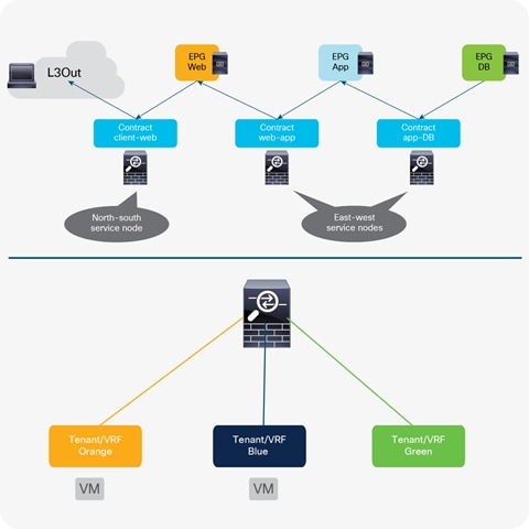
North-south perimeter firewall and east-west firewall
For each scenario, the following deployment alternatives are discussed:
● Active-standby service node pair stretched across pods
● Transparent firewall
● Routed firewall as default gateway for the endpoints
● Routed firewall with L3Out peering
● Routed firewall with PBR
● Active-active service node cluster stretched across pods
● Routed firewall with PBR
● Independent active-standby service node pair connected to separate pods
● Routed firewall with L3Out peering
● Routed firewall with symmetric PBR
Although this document doesn’t specifically covers the details, the following design options are also valid.
● Other service node such as inline (Layer 1 mode) service node, Intrusion-Prevention System (IPS), and load-balancer
● Inline or transparent (Layer 1 or Layer 2 mode) service node with PBR (starting from Cisco APIC Release 4.1.)
● PBR destination in an L3Out instead of a BD (starting from Cisco APIC Release 5.2.)
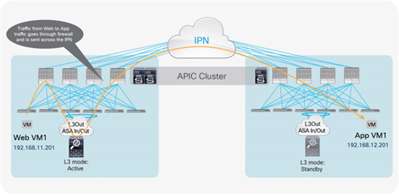
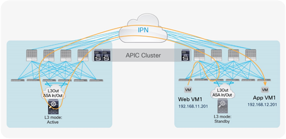
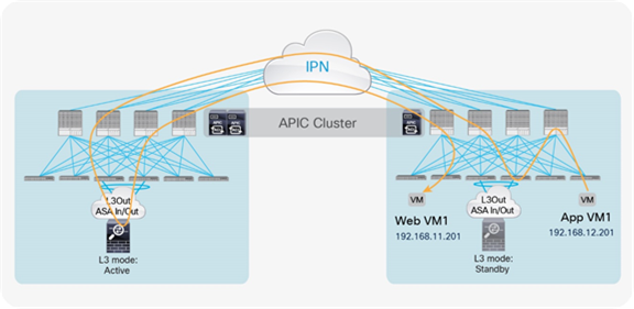
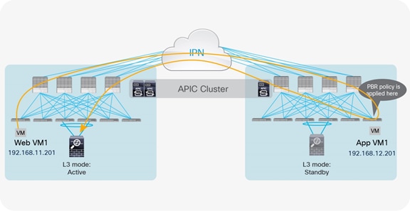
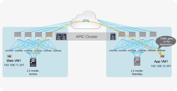
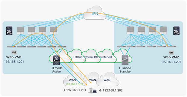
Active-standby firewalls pair stretched across pods
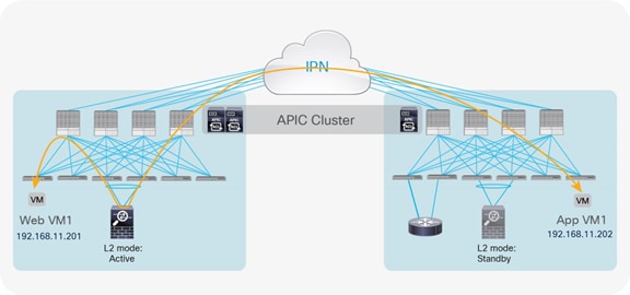
One of the most common options is the deployment of an active-standby service node pair in different pods. In the example in Figure 3, the active firewall node is in Pod1 and the standby node is in Pod2. In this case, all the traffic for communication with the external network (north-south) or between internal endpoints (east-west) must be hair-pinned to the pod in which the active service node is located.
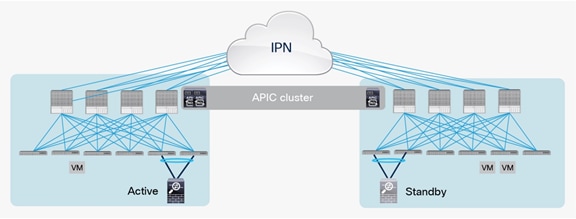
Active-standby service node pair connected to separate pods
A separate physical (or virtual) firewall can be deployed for each tenant (Virtual Networking and Forwarding [VRF] instance) that requires firewall policy enforcement. Notice also that each firewall node can be connected in a Virtual Port Channel (vPC) to a pair of Cisco ACI leaf nodes (as shown in Figure 3), or to only a single leaf node (with a local port channel). Different considerations apply depending on the specific firewall configuration option, as will be clarified in the following sections. For each option, we’ll distinguish between the use case of firewall policy enforcement for north-south or east-west traffic flows.
Option 1: Transparent firewall
North-south perimeter firewall integration use case
The north-south perimeter service node integration use case focuses on traffic flows between the external Layer 3 network domain and the web EPG.
Figure 4 shows the typical Cisco ACI network design for insertion of a north-south transparent firewall. To make traffic go through a transparent firewall, you use a bridge domain “sandwich” design.
North-south transparent firewall design
The default gateway for the server part of the Web EPG is deployed in the Cisco ACI fabric (distributed anycast gateway) and is available in the bridge domain in which the firewall external interface is connected. Notice how this is a different bridge domain than the one in which the web server is located. This configuration forces all traffic destined for external destinations to traverse the transparent firewall.
You can use all service graph models or no service graph at all for this design. In all cases, traffic is enforced through the active firewall based on Layer 2 lookup operations performed by the Cisco ACI leaf nodes either on the traffic received from the endpoint (south-to-north traffic) or on the traffic routed to the destination IP subnet (north-to-south traffic).
Note: A managed-mode service graph requires a device package and an L4-L7 logical device containing one or more concrete devices. The L4–L7 logical device is managed through a single management IP address representing the point of contact for the APIC to push the configuration. Assuming that the active-standby service node pair has a configuration synchronization mechanism (which is normally the case), you can use a managed-mode service graph in this case.
When you use traditional L3Out for external network connectivity, the web server subnet is advertised through border leaf nodes in different pods. Depending on the specific configuration, incoming traffic may be steered toward any pod that has a local L3Out interface defined, independent from the location of the active Layer 2 service node.
If the destination endpoint and the active service node are connected to the same pod to which incoming traffic is steered, traffic is not hair-pinned across the IPN for ingress and egress flows (Figure 5).
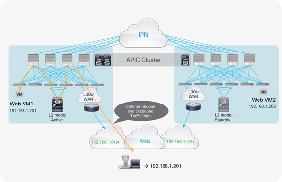
Optimal traffic path example with traditional L3Out
If those entities are connected in different pods, traffic will be hair-pinned across the IPN to be sent through the service node before it reaches the web destination endpoint. Figure 6 shows the worst-case scenario, in which a double bounce across the IPN is required to deliver external traffic to the web endpoint connected in Pod2.
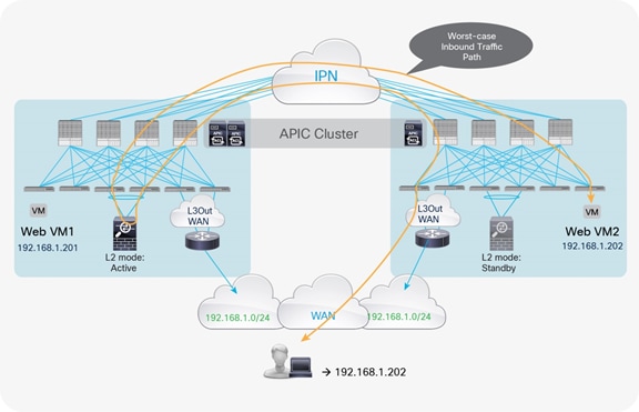
Example of double traffic hair-pinning with traditional L3Out
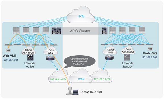
Return traffic originating from the web endpoint by default always uses the local L3Out connection in the pod in which the active service node is connected, as shown in Figure 7.
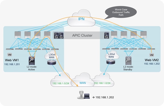
Worst-case outbound path with traditional L3Out
A possible way to minimize the suboptimal behavior shown in Figure 6 is to introduce the concept of the “home site” for a given service or application. In the context of this document, the home site represents the pod in which the active service node is deployed at steady state (that is, without considering the active service node failure condition). You should help ensure that routing information sent to the WAN for an IP subnet extended across pods using the Layer 2 extension capabilities of the Cisco ACI Multi-Pod solution always steers incoming traffic toward the home site (Figure 8).
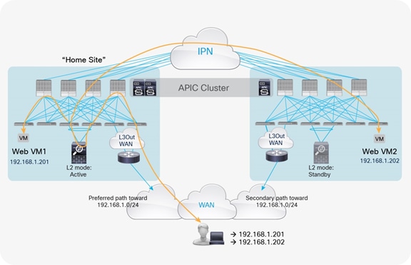
Note: The creation of the inbound preferred path shown above can be achieved in different ways, depending on the deployment details. This topic is beyond the scope for this document.
With this approach, traffic destined for the local endpoints (Web VM1 in the example in Figure 8) is optimally handled. In the worst-case scenario, in which the destination endpoint has been moved to a different site, traffic will have to bounce across the IPN only one time, avoiding the worst-case scenario previously shown.
Another option is to enable host-route advertisement out of the Cisco ACI fabric to inject granular routing information into the external Layer 3 network domain. As previously mentioned, this functionality is available on ACI border leaf nodes starting from ACI release 4.0. For previous releases, it requires instead the deployment of GOLF L3Outs.
In the scenario discussed in this section, the IP addresses for all the web endpoints are learned in the bridge domain connected to the external service node interface, because it is the one with the default gateway defined. As a consequence, host routes for all the endpoints are always advertised out of the pod in which the active service node is connected. This approach implies an optimal behavior only for communication with endpoints that are deployed in the same pod, as shown in Figure 9.
Optimal traffic path with host routes advertisement
At the same time, if the destination endpoint is not located in the same pod as the active service node, traffic hair-pinning occurs between the internal interface of the service node and the destination endpoint (Figure 10).
Traffic hair-pinning with host routes advertisement
In summary, the enablement of host-routes advertisement with a perimeter transparent firewall does not always allow you to optimize communication with the external Layer 3 domain. However, it at least avoids the worst double-hair-pinning scenario, shown in Figure 6.
East-west firewall integration use case
Figure 11 shows the typical Cisco ACI network design for east-west transparent firewall insertion. This design is similar to that for the north-south firewall use case. In this case, the consumer and provider endpoints are part of the same IP subnet and can communicate only by traversing the transparent firewall. This restriction is ensured by the proper population of Layer 2 forwarding tables on the Cisco ACI leaf nodes. For example, the MAC addresses of all the endpoints belonging to the EPG web are learned through the internal firewall interface (and vice versa).
You can use an unmanaged-mode service graph, a managed-mode service graph, or no service graph at all for this design.
East-west transparent firewall design
If the source endpoint, the destination endpoint, and the active service node are in the same pod, traffic remains confined within the pod (Figure 12).
Optimal traffic path example (within the pod)
If either the source or destination endpoint is not in the same pod with the active service node, traffic must hair-pin across the IPN (Figure 13).
Cross-pod traffic path example
Note: The behavior described above applies independently from the fact that the two EPGs are part of separate Bridge Domains under the same VRF or part of separate BDs under different VRFs (same tenant or across tenants).
Option 2: Routed firewall as default gateway for the endpoints
Figure 14 shows the integration of a firewall deployed as the default gateway for the endpoints.
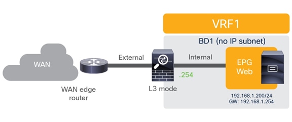
Routed firewall as default gateway for the endpoints
In this deployment model, the Cisco ACI fabric is simply offering Layer 2 connectivity services to allow the endpoints to communicate with their default gateway (the firewall) and for the firewall to route traffic between endpoints belonging to separate IP subnets and between the endpoints and the external Layer 3 network domain.
The internal interfaces of the firewall are part of the EPGs/BDs where the endpoints are connected. For the external interface, it is possible to have the firewall connected to a specific EPG/BD providing Layer 2 connectivity services toward the external routers or having the firewall directly connected to those routers.
Since no L3Out connections need to be defined on the Cisco ACI fabric, the firewall is inserted into the traffic paths simply based on Layer 2 lookup operations performed on the ACI leaf nodes.
As a consequence, the corresponding traffic paths for north-south and east-west connectivity are essentially identical to the one shown in the figures for the previously discussed Option 1, with the only difference that no L3Out is required between the Cisco ACI fabric and the external routers. Those external routers simply connect to the ACI fabric in the same EPG/BD where the outside interface of the firewall is connected.
Note: Traffic hair-pinning across the IPN happens also in this case, depending on where the endpoints are connected and how the traffic is entering the Cisco ACI fabric, as a result of the fact that a single active path (the active firewall node) is available.
Option 3: Routed firewall with L3Out peering with the Cisco ACI fabric
North-south perimeter firewall integration use case
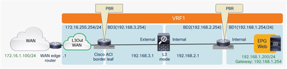
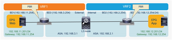
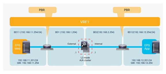
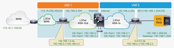
Figure 15 shows the Cisco ACI network design for insertion of a north-south routed firewall when the firewall nodes are connected to the Cisco ACI fabric via L3Out peering.
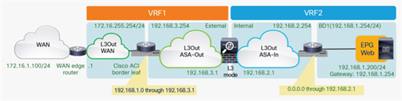
North-south routed firewall design with L3Out peering
This approach allows use of the anycast gateway function offered by the Cisco ACI fabric (bridge domain subnet) and deployment of the firewall as a routed Layer 3 hop at the front-end of the VRF instance. The idea here is that communication within VRF instances won’t need to traverse the perimeter firewall, which, instead, applies security policies only on north-south communication to other VRF instances or to the external Layer 3 domain.
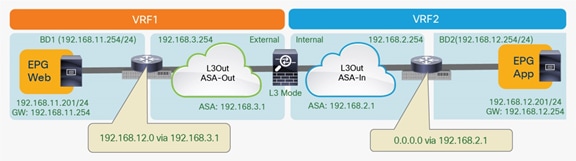
In this model, L3Out connections are established between the fabric and the internal and external firewall interfaces. A classic VRF sandwich configuration is hence required to enforce traffic through the routed firewall. The web subnet and the IP subnet of the firewall internal interface are associated with a firewall inside the VRF2 instance. The firewall outside interface and the Layer 3 interface to the WAN edge router are instead part of the VRF1 instance.
You can use any service graph option or no service graph at all for this design. In all the cases, traffic is enforced through the active firewall based on Layer 3 lookup operations performed by the Cisco ACI leaf nodes.
Two options are available to create the L3Out connections between the Cisco ACI leaf nodes and the active-standby service nodes deployed across pods:
● You can define separate L3Out connections for each pod, each including the local pair of leaf nodes to which the firewall is connected.
● As a recommended approach, you can instead use the same L3Out connections including all four leaf nodes deployed across pods to which the active-standby firewalls are connected.
Some important functional and design considerations apply to these two options, as discussed in the following sections. To fully understand the differences, remember that a defined L3Out connection always has an associated bridge domain (external bridge domain). The use of separate L3Out connections in each pod means that each has a unique local external bridge domain associated with it, whereas in the single-L3Out scenario, the external bridge domain is stretched across pods.
Use of separate L3Out connections across pods
The definition of two separate L3Out connections, as shown in Figure 16, creates two separate bridge domains that remain confined within each pod.
Use of separate L3Out connections across pods
Notice that the leaf nodes in each pod still can be assigned IP addresses in the same IP subnet for their Switch Virtual Interfaces (SVIs) that connect to the firewall node.
Note: A similar configuration (using different IP subnets) must be applied on the L3Out connections used to connect to the external and internal firewall interfaces. The example in Figure 16 focuses on connectivity only to the external firewall.
Because the bridge domain is not extended across pods, when you use a dynamic routing protocol only the service leaf nodes connected to the active firewall can establish routing adjacencies with it and exchange reachability information. This approach helps ensure that all traffic flows originating from web endpoints are steered toward those leaf nodes, independent of the pod in which the web endpoints are located (Figure 17).
Outgoing traffic flows directly sent to the active firewall node
Several important considerations are associated with this deployment option:
● You can use separate L3Out connections with Cisco ASA, because after a failover event the standby unit that is activated acquires the MAC and IP addresses of the failed unit. Some third-party firewalls instead use a protocol such as Virtual Router Redundancy Protocol (VRRP) on the data VLAN to assign the active IP and MAC addresses. In this case, the only possibility is to extend the bridge domain across pods by creating a single L3Out connection (as discussed in the section “Use of a single L3Out connection across pods”).
● The failure of the active firewall triggers a failover event that activates the standby firewall in the remote pod. Routing peering must then be re-established between the newly activated firewall and the leaf nodes connected to it (Figure 18). This scenario implies a longer traffic outage, mostly depending on the specific dynamic routing protocol behavior.
Use of separate L3Out connections across pods (firewall failover scenario)
The configuration of a common secondary IP address on leaf nodes (shown in Figure 18) is required only with static routing, because it represents the next hop used on the firewall node to route traffic to the Cisco ACI fabric. However, static routing with separate L3Out connections does not work (and therefore is not supported). In the current implementation, in fact, even the leaf nodes connected to the standby firewall would redistribute the static route information to the Cisco ACI Multiprotocol Border Gateway Protocol (MP-BGP) VPN Version 4 (v4) control plane. As a consequence, traffic originating from web endpoints connected to each pod would first be steered toward the local leaf nodes connected to the service node, independent of the state (active or standby) of the service node itself (Figure 19).
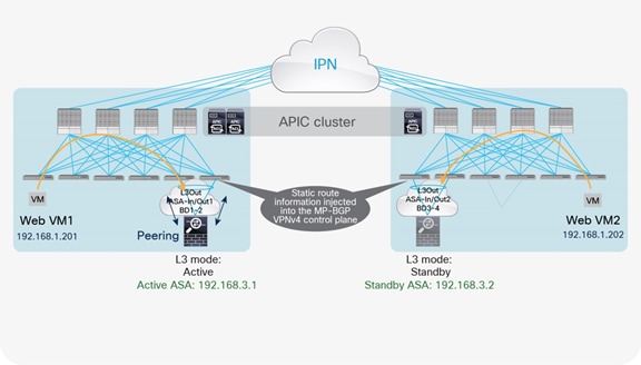
Outgoing flows always preferring the local service leaf nodes
At that point, the leaf nodes connected to the standby firewall can’t resolve the MAC address of the next-hop IP address representing the interface of the active firewall (MAC address of 192.168.3.1 in this example) because the L3Out bridge domain is not extended across pods (Figure 20).
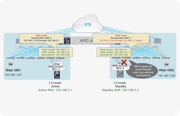
Use of separate L3Out connections across pods and static routing (not supported)
Note: Starting from Cisco ACI release 4.1, IP-SLA tracking is introduced, which can influence routing table based on tracking status. By enabling IP-SLA tracking feature in the static route to track the active firewall IP (192.168.3.1), the static route can be removed on the leaf node where the standby firewall is connected. So that the situation described in figure 19 and 20 can be avoided. The current maximum verified number of IP-SLA tracking IPs is 100 per leaf node and 200 per ACI fabric.
In summary, the use of separate L3Out connections mandates the use of a static route with IP-SLA or a dynamic routing protocol between the firewall and the Cisco ACI border leaf nodes and the dynamic routing option would result in longer north-south traffic outages after a firewall failover event. As a consequence, the recommended approach is the use of a single L3Out connection, described in the following section.
Use of a single L3Out connection across pods
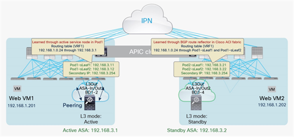
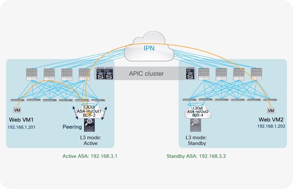
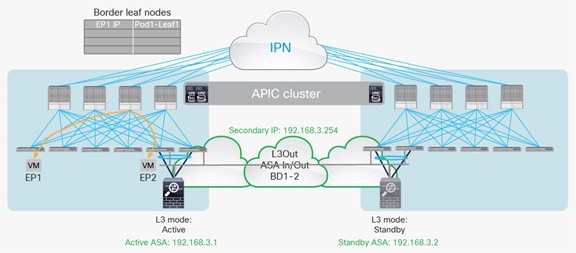
The use of the same L3Out connection as the service leaf nodes located in separate pods implies the extension of the external (or internal) bridge domain across pods, as shown in Figure 21. In this model, the service leaf pairs in Pod1 and Pod2 both can establish routing adjacencies with the active firewall and exchange routing information with it.
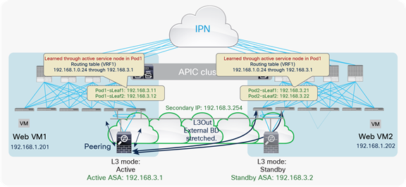
Use of a single L3Out connection across pods with dynamic routing
Note: The extension of the logical segment shown in the figure above is achieved leveraging Cisco ACI Multi-Pod (that is, using VXLAN tunnels across the IPN network).
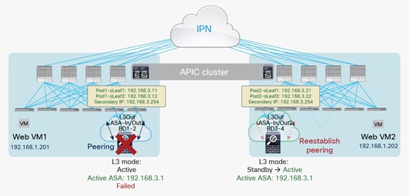
This deployment option improves the convergence time for a firewall failover event, because routing adjacencies with the newly activated firewall node don’t need to be reestablished (Figure 22).
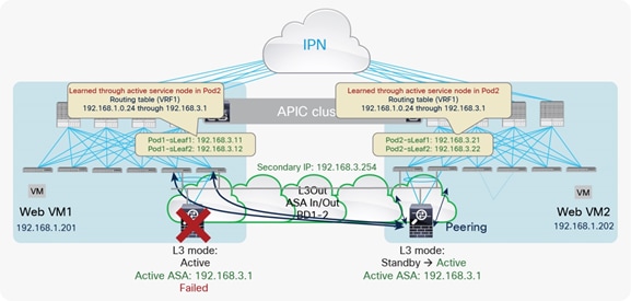
Use of a single L3Out connection across pods with dynamic routing (firewall failover scenario)
Establishing peering between the active firewall and the service leaf nodes across pods implies that both pairs of switches always advertise in the Cisco ACI MP-BGP VPNv4 control plane the routing prefixes learned from the active firewall. As result, the traffic paths between the web endpoints and the external Layer 3 network domain would look like the one previously shown in Figure 19. Computing leaf nodes deployed in the pod with the standby firewall would always first send the traffic to the local service leaf nodes. The service nodes would then need to bounce the traffic to the service leaf nodes connected to the active firewall in the remote pod, as shown in Figure 23.
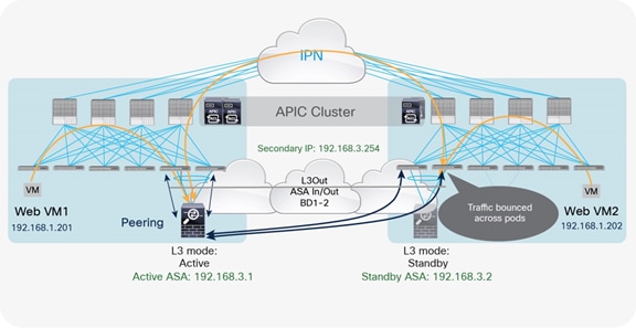
Bouncing outgoing flows sourced from web endpoints in Pod2
Be sure to note that this capability to bounce traffic across pods when the firewall nodes are connected in vPC mode to the Cisco ACI leaf nodes is supported only starting from Cisco ACI releases 2.1(3), 2.2(3), 2.3(1), and 3.0(1) and requires Cisco Nexus 9000 Series EX or FX platform hardware for the leaf switches on which the firewall is connected.
You can deploy an alternative design, supported instead from Cisco ACI releases 2.1(2), 2.2(2), 2.3(1), and 3.0(1), on all Cisco ACI leaf switches by connecting the firewall node to a single leaf node (either with an individual physical interface or with a port channel), as shown in Figure 24.
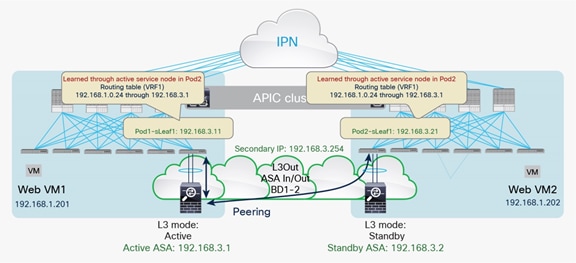
Use of a single L3Out connection across pods (connecting to a single service leaf node)
As shown earlier in Figure 15, an L3Out connection is also required between the Cisco ACI fabric and the WAN edge routers to provide connectivity to the WAN. When you use traditional L3Out connections on the border leaf nodes for external connectivity, the server subnet is advertised through the border leaf nodes in different pods. Depending on the specific configuration, incoming traffic from the external network may arrive on one of the pods. Then traffic will have to transit the active service node before finally reaching the destination.
If the destination endpoint, the active service node, and the external router advertising the subnet with the best cost are in the same pod, traffic hair-pinning doesn’t occur, as shown in Figure 25.
Optimal traffic path example with traditional L3Out
If the active firewall and the destination endpoints are deployed in different pods, the traffic will be hair-pinned across the IPN. This is dependent on both having a single active perimeter firewall connected to the Multi-Pod fabric and on the fact that the web virtual machines are deployed across pods.
As previously mentioned the definition of a home site will minimize the hair-pinning of traffic across the IPN, which will be required only when destination endpoints migrate from the home site at which the active service node is deployed.
Similar considerations apply for the deployment of GOLF L3Outs, which does not bring any advantage compared to Border Leaf L3Outs in terms of traffic path optimization.
One last design consideration for the use of a single L3Out across pods arises in the specific scenario where endpoints are connected to the border leaf nodes where such L3Out is configured.
Communication with endpoint connected to the border leaf nodes
In the example in Figure 26, the endpoint EP1 is sending traffic to another endpoint EP2 connected to the border leaf nodes in the same Pod1. This traffic causes one of the border leaf switches in Pod1 to learn the remote IP endpoint for EP1 pointing to Leaf 1.
Figure 27 shows what happens when EP1 is migrated to Pod2. If EP1, now in Pod2, is trying to reach the firewall, the traffic is forwarded to the border leaf switches in Pod2 because they know the routes directly from the active firewall, and the local border leaf switches are preferred over the border leaf switches in another pod.
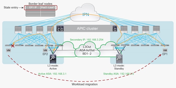
Workload migration and creation of stale entry
Next, the traffic is looked up on the border leaf in Pod2, and the next-hop MAC address for the active firewall is resolved on it through an ARP entry on the same border leaf. However, the active firewall is not physically connected to the same border leaf. Hence, the traffic is bridged to the border leaf switches in Pod1 through the Inter-Pod Network (IPN) connection. This traffic does not update the IP address information associated to EP1 on the border leaf in Pod1 because this traffic is switched and not routed. Therefore, only the remote MAC address is learned, not the IP address.
Because of this, return traffic from the active firewall, or any other traffic destined to EP1’s IP and originated from the border leaf, hits the previous stale remote endpoint for EP1 pointing to the previous leaf. This behavior could cause a loss of traffic toward IP1 from this border leaf.
Note: After EP1 migrates to Pod2, a bounce entry is installed in Leaf1 to prevent traffic black-holing. However, the issue of traffic dropping would restart as soon as the bounce entry expires.
The issue described in Figure 27 can be avoided if the Disable Remote EP Learn option is enabled when the VRF instance uses ingress policy enforcement mode (the default configuration). In that case, the border leaf switches in each pod will not learn the information for the remote endpoints part of that VRF instance; that can prevent this concern. It is therefore strongly recommended; the best-practice configuration is to disable Remote EP learning.
East-west firewall integration use case
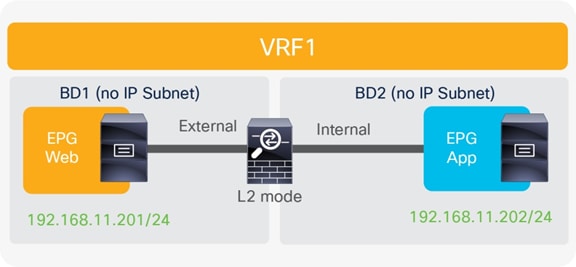
Figure 28 shows the typical Cisco ACI network design for east-west routed firewall insertion with L3Out peering. This design is similar to that for the north-south firewall integration use case. The routed path between the web EPG and app EPG always goes through the active firewall, no matter in which pod it is deployed. Routing information can be learned dynamically using a routing protocol, or it can be configured statically.
You can use an unmanaged-mode service graph, a managed-mode service graph, or no service graph at all for this design.
East-west routed firewall design with L3Out peering
Note: An alternative deployment model could leverage virtual firewall instances front-ending each VRF. Inter-VRF communication could, in that case, be enabled through a “fusion router” device connecting together the various firewall contexts, as shown in Figure 29. Notice that, in this example, the “fusion router” function is performed by the Cisco ACI fabric, but it could also be moved to an external router connected to the fabric.
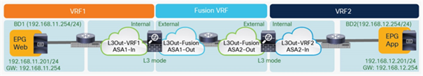
East-west routed firewall design with virtual firewall contexts
The considerations below apply to both of the models described in the previous two figures.
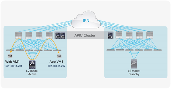
If the source endpoint, the destination endpoint, and the active service node are in the same pod, traffic is optimally confined within the pod (Figure 30).
Optimal traffic path example (within the pod)
If either the source or destination endpoint is not in the same pod with the active service node, traffic is sent across the IPN (Figure 31).
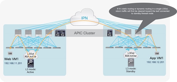
Optimal traffic path example (across pods)
Note: When static routing is used, the return traffic between the application and web virtual machines in Figure 31 will first be steered toward the leaf connected to the standby firewall node located in the same pod as the application virtual machine. The traffic then will bounce across pods to reach the active firewall. Thus, in terms of software support for this function, the same considerations as discussed in the section “Use of a single L3Out connection across pods” for north-south communication apply here as well.
If both the source and the destination endpoints are not in the same pod with the active service node, traffic hair-pins across the IPN.
Example of traffic hair-pinning across the IPN
Option 4: Routed firewall with PBR
North-south firewall integration use case
Figure 33 shows the typical Cisco ACI network design for north-south routed firewall insertion with PBR. The use of PBR significantly simplifies the configuration, because the previously described VRF sandwich configuration is not required anymore. The traffic is instead redirected to the active service node based on the configured policy.
North-south routed firewall design with PBR
PBR mandates the use of a service graph, so you must use an unmanaged-mode service graph or managed-mode service graph with this design option. For more information about how to configure PBR, refer to the document at https://www.cisco.com/c/en/us/solutions/data-center-virtualization/application-centric-infrastructure/white-paper-c11-739971.html
As of this writing, the following are the specific requirements for the use of PBR:
● The PBR node and the Cisco ACI fabric both must be configured in routed mode.
Note: The term “PBR node” refers to the network services node (Firewall, SLB, etc.) specified in the PBR policy.
● The PBR service node interfaces must be part of regular bridge domains and not connected to an L3Out connection.
● The PBR service node interfaces can be part of the consumer/provider bridge domain or you can define different, dedicated bridge domains, as shown in Figure 33.
● The bridge domains used to connect the interfaces of the PBR node (BD2 and BD3 in the example in Figure 33) must be configured with data-plane learning disabled if first generation leaf switches are used.
● PBR is supported on all Cisco ACI leaf switches. However, with first-generation Cisco Nexus 9000 Series hardware switches you must use dedicated service leaf nodes to connect the PBR node. This limitation is lifted with EX and FX platform leaf switches, in which consumer or destination endpoints can also be connected to the service leaf nodes.
● The active service nodes should always use the same virtual MAC (vMAC) address, because traffic redirection is performed by rewriting destination the MAC address to the vMAC address. This requirement implies that when a firewall failover event occurs, the standby unit that is activated must start using that same vMAC address (this is the case with Cisco ASA and Cisco Firepower models).
● The PBR node can be deployed in “two-arm” modes, as displayed in Figure 33, or in “one-arm” mode with a single interface connected to a service Bridge Domain. The latter option is preferable since it simplifies the routing configuration of the PBR node, which only requires a default route pointing to the ACI anycast gateway address defined on the service Bridge Domain.
The PBR configuration helps ensure that traffic originating from the external Layer 3 domain always is forced through the active firewall node before being delivered to the web endpoint destination. This routing occurs based on the configured policy, independent of the information contained in the routing table of the leaf nodes, which instead would mislead you to believe that communication can occur directly because the L3Out and the web bridge domain are part of the same routing domain (VRF1). This operational consideration is important to remember when you are troubleshooting a PBR deployment.
When you use a traditional L3Out connection, the web server subnet is advertised through border leaf nodes in different pods. Depending on the routing information in the WAN, incoming traffic will be steered toward one of the pods. Then the PBR policy will be applied on the leaf node that knows both the consumer and provider class IDs, because the policy is based on the source and destination EPGs and the filter configured in the contract. Hence, traffic will be redirected to the active service node to finally reach the destination endpoint.
In the example where the internal EPG and the L3Out are defined in the same VRF (as shown in Figure 33) and with the default VRF configuration (that is, ingress policy enforcement), the border leaf node doesn’t learn location information for internal endpoints when a contract with PBR is created between the external EPG and the web EPG. Therefore, that traffic received from the external network must first be encapsulated to the spine proxy VXLAN Tunnel Endpoint (VTEP). The receiving spine node then sends it to the leaf node to which the destination endpoint is connected. At that point, the PBR policy can be applied (because the leaf node knows both the source and destination class IDs), and traffic is redirected to the active service node. After the firewall node applies the configured security policy, the traffic is then sent back to the destination endpoint, again using the proxy services on the spine nodes because endpoint learning is not enabled on the service leaf nodes to which the firewall node is connected.
In the best-case scenario, in which the destination endpoint and the active firewall are part of the same pod to which ingress traffic is directed, the traffic follows the optimal path, and there is no hair-pinning across the IPN, as shown in Figure 34.
Example of optimal inbound traffic with traditional L3Out
Note: In case the internal EPG and the L3Out are part of separate VRFs, the leaf where the PBR policy is applied would depend on the contract’s direction. Table 2, below, summarizes the policy enforcement in the different use cases.
Table 2. Where policy is applied
| Scenario |
VRF enforcement mode |
Consumer |
Provider |
Policy enforced on |
| Intra-VRF |
Ingress/egress |
EPG |
EPG |
If destination endpoint is learned: ingress leaf* If destination endpoint is not learned: egress leaf |
| Ingress |
EPG |
L3Out EPG |
Consumer leaf (non-border leaf) |
|
| Ingress |
L3Out EPG |
EPG |
Provider leaf (non-border leaf) |
|
| Egress |
EPG |
L3Out EPG |
Border leaf -> non-border leaf traffic If destination endpoint is learned: border leaf If destination endpoint is not learned: non-border leaf Non-border leaf-> border leaf traffic Border leaf |
|
| Egress |
L3Out EPG |
EPG |
||
| Ingress/egress |
L3Out EPG |
L3Out EPG |
Ingress leaf* |
|
| Inter-VRF |
Ingress/egress |
EPG |
EPG |
Consumer leaf |
| Ingress/egress |
EPG |
L3Out EPG |
Consumer leaf (non-border leaf) |
|
| Ingress/egress |
L3Out EPG |
EPG |
Ingress leaf* |
|
| Ingress/egress |
L3Out EPG |
L3Out EPG |
Ingress leaf* |
For the return traffic, the PBR policy can be directly applied on the leaf node to which the web virtual machine is connected. The traffic is henceforth redirected to the active service node and then goes back to the external Layer 3 domain (Figure 35).

Example of optimal outbound traffic with traditional L3Out
Note: The behavior shown in Figure 35 for the return traffic is valid assuming that the default ingress setting at the VRF level is maintained for the policy control enforcement direction. Changing the setting to egress would instead cause the PBR policy for return traffic to be applied on the border leaf nodes.
In scenarios where inbound traffic is instead received in the pod where the destination endpoints are not connected, traffic will be forced to hairpin across the IPN. Once again, this is mainly because the firewall service is deployed in active/standby mode across the pods.
Similar considerations apply for the deployment of GOLF L3Outs. Even the host route advertisement capability currently supported with this option does not bring many advantages when deploying an active/standby firewall pair across pods.
East-west firewall integration use case
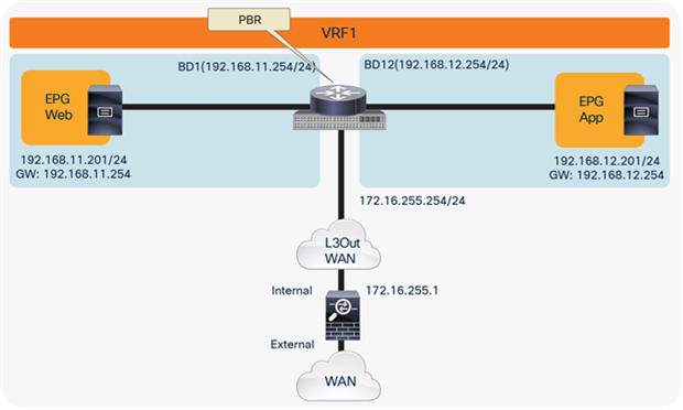
Figure 36 shows the typical Cisco ACI network design for east-west routed firewall insertion with PBR when the EPGs are part of the same VRF. This design is similar to that for the north-south firewall use case. The internal and external interfaces of the firewall node are connected to two dedicated bridge domains, different from the ones in which the consumer and provider endpoints are deployed.
Note: Starting from release 3.1 it is also possible to connect the firewall interfaces to the same bridge domains where the endpoints are connected.
You can use an unmanaged-mode service graph or managed-mode service graph for this design.
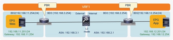
East-west routed firewall design with PBR
The place at which the PBR policy is applied depends on whether the leaf can resolve both the source and destination EPG class IDs. This example assumes the worst-case scenario (from the perspective of traffic flow), in which the source or destination leaf nodes have not learned remote endpoint class-ID information. As previously mentioned, this behavior would always be the case when a PBR policy is the only contract existing for those EPGs.
If the source endpoint, the destination endpoint, and the active service node are in the same pod, traffic remains confined within the pod. Based on the assumption just discussed, the PBR policy is applied on the destination leaf, and then traffic is redirected to the service node (Figure 37, Figure 38 and Figure 39).
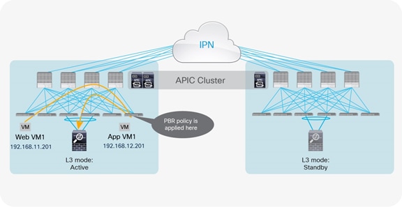
Optimal traffic path example (within the pod: traffic from web to application, part 1)
Optimal traffic path example (within the pod: traffic from web to application, part 2)
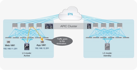
Optimal traffic path example (within the pod: traffic from application to web)
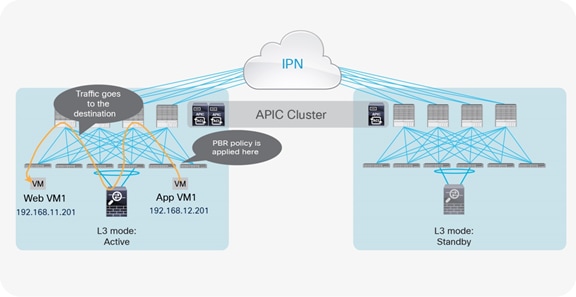
If either the source or destination endpoints are not in the same pod as the active service node and the PBR policy is applied on the destination leaf, traffic will hair-pin twice across the IPN. Figure 40 and Figure 41 show this worst-case scenario.
Example of worst-case traffic hair-pinning across the IPN (part 1)
Example of worst-case traffic hair-pinning across the IPN (part 2)
The suboptimal traffic path shown in Figure 40 and Figure 41 is the direct result of spreading endpoints and service nodes across the pods.
Similar considerations apply if the firewall node must be inserted between EPGs that are part of separate VRF/tenants, as shown in the example below.
East-west routed firewall design with PBR across VRFs
When inserting a firewall between EPGs deployed in separate VRFs, the PBR policy is always applied on the consumer leaf; therefore, the worst case scenario in terms of traffic hair-pinning would be when the consumer endpoint is in one pod, and the provider endpoint and active firewall are in a remote.
Note: The PBR node can be between VRF instances (as in the example above) or within one of the VRF instances. The PBR node must be in either the consumer or provider VRF instance; you cannot put the PBR node in a different VRF, which is neither a consumer nor a provider VRF instance.
Option 5: Routed firewall with L3Out peering and PBR
This approach uses the same routed firewall for north-south communication (by using traditional Layer 3 lookup) and for east-west traffic flows by using PBR. This approach requires Cisco APIC Release 5.2 or later, which introduces the use of a PBR destination connected to an L3Out (instead that to a Service BD).
The value proposition for this approach consists in giving the capability of deploying a single instance of service nodes for both north-south and east-west communication (as in the previously discussed Option 4 PBR-based), but still ensuring security policy enforcement on the FW for that traffic sourced in the external network before being received on the ACI border leaf nodes.
North-south perimeter firewall integration use case
Figure 43 shows one of the examples of Cisco ACI network design for insertion of a north-south routed firewall where the internal interface of the firewall nodes is connected to the Cisco ACI fabric through L3Out peering. Though it’s not illustrated in this section, the following design options are valid:
● Both the external interface and the internal interface of the firewall nodes are connected to the Cisco ACI fabric through L3Out peerings. (Figure 15 in option 3)
● The external interface of the firewall node is connected to the Cisco ACI fabric through an L2 bridge domain, and the internal interface of the firewall node is connected to the Cisco ACI fabric through an L3Out peering.
● The external interface of the firewall node is not connected to the Cisco ACI fabric. The internal interface of the firewall node is connected to the Cisco ACI fabric through an L3Out peering.
The difference between this example and option 3 north-south use case is that the external interface of the firewall nodes are not connected to the Cisco ACI fabric, which means the firewall nodes are always inserted for the traffic between the external network and the Cisco ACI fabric.
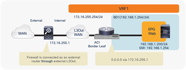
North-south routed firewall design with L3Out peering
This approach allows the use of the anycast gateway function offered by the Cisco ACI fabric (bridge domain subnet) and deployment of the firewall as an external routed Layer 3 next hop at the VRF. The idea here is that communication within the VRF won’t need to traverse the perimeter firewall, which, instead, applies security policies only on north-south communication to the external Layer 3 domain (or, optionally, to resources deployed in different tenants/VRFs).
In this model, L3Out connections are established between the Cisco ACI fabric and the internal interface of the firewall. The external interface of the firewall is connected to the outside of the Cisco ACI fabric. No service graph is required for this design.
Traffic is enforced through the active firewall based on Layer 3 lookup operations performed by the Cisco ACI leaf nodes (Figure 44). As in option 3 north-south use case, it’s recommended to use the same L3Out connections between the Cisco ACI leaf nodes and the active-standby service nodes deployed across pods.
East-west firewall integration use case
Figure 45 shows a Cisco ACI network design example for east-west routed firewall insertion with PBR when the EPGs are part of the same VRF. Although this design is similar to that for option 4 east-west firewall use case, the important difference is that the firewall is connected through the external L3Out used for north-south traffic inspection. This design requires an unmanaged-mode service graph and Cisco APIC Release 5.2 or later for PBR destination in an L3Out.
As previously mentioned, this approach allows the use of the same firewall for both north-south and east-west traffic inspection. The idea here is that north-south communication is always inspected by the perimeter firewall based on routing, and east-west communication can be inspected by the same firewall using PBR if needed.
It is also possible to use the following design options:
● The use of the same bridge domain subnet for the consumer and the provider EPGs.
● The use of different VRFs for the consumer and the provider EPGs. (The L3Out for the PBR node must be in either the consumer or the provider VRF.)
East-west routed firewall design with PBR destination in an L3Out
Traffic hair-pinning consideration is same with option 4 east-west firewall use case. Please refer to the explanations provided for Figures 37 to 41.
Active-active firewall cluster stretched across separate pods
In this scenario an active/active firewall cluster is integrated into the Cisco ACI Multi-Pod fabric. The firewall nodes that are part of the same cluster are all active and deployed to separate pods. Different firewall vendors offer different “active/active clustering” functionalities. The deployment model discussed in this section of the document specifically refers to the scenario where all the nodes that are part of the same cluster share the same MAC/IP address combination, and so appear to the rest of the network as a single logical entity. This is the “active/active” model supported by the Cisco ASA or Cisco Firepower firewall appliances, which takes the name of “split spanned EtherChannel” model.
Note: For more information on “spanned EtherChannel” support on Cisco firewalls, please refer to the document below:
Figure 46 shows the deployment of a stretched active-active firewall cluster across separate pods.
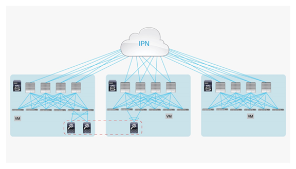
Active-active service cluster stretched across separate pods
Some specific deployment considerations are the following:
● This deployment model assumes that all the firewall nodes in the same cluster use the same IP and MAC address. If each firewall node uses an independent IP and MAC for each node, the deployment model is independent active-standby firewalls pair in each pod.
● It is not required to have firewall nodes deployed in every pod.
● All of the firewall nodes deployed in a pod must be connected to a single pair of ACI leaf nodes. A single vPC connection is configured on the ACI leaf nodes for connecting to all the local firewall nodes, giving the Cisco ACI fabric the impression of being connected to the same logical device.
● The maximum number of firewall nodes that can be clustered together is 16.
● The maximum recommended latency (round trip time: RTT) for stretching the firewall cluster is around 20 msec RTT (for the Cluster Control Link). Notice how this value is lower than the 50 msec RTT maximum latency that is supported between pods belonging to an ACI Multi-Pod fabric.
● The service node cluster needs to be deployed in routed mode. Deploying an active/active cluster in Layer 2 mode stretched across pods is not supported.
● Leaf switches must be Cisco Nexus 9000 Series EX or FX platform hardware.
● Prior to the 4.1 release, you must disable the IP aging policy.
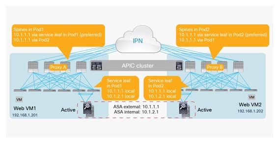
Prior to Cisco ACI release 3.2(4d), the use of the same MAC/IP combination on firewall nodes connected to separate pods would have led to the creation of duplicated IP/MAC entries across pods. With the introduction of the “anycast service” feature in release 3.2(4d), the IP/MAC of the cluster can be configured as an anycast endpoint. This causes the spine in a pod to learn the anycast IP/MAC pod-local, while keeping the same MAC/IP entry of the other pods as a backup path.
The specific MAC/IP combination is only learned on the leaf nodes where the firewall nodes (anycast service) are directly attached; those leaf nodes then send a COOP update to the spines. From the spine nodes, the path to local attached anycast entry is always preferred. In case of a failure of all local service cluster nodes, the backup path to another pod is chosen.
Figure 47 shows the learning of anycast service IP/MAC information across separate pods. In theory, this functionality can be used with any service that provides an anycast functionality (the same IP/MAC across different devices, state sync, etc.). The deployment of a stretched firewall cluster is just a specific application of this new functionality.
For the deployment of a stretched firewall cluster, it is essential that the clustered service support a traffic redirection functionality across cluster nodes to ensure that connections will not be dropped, whichever specific firewall nodes in the cluster are receiving the traffic. In the specific Cisco ASA/FTD {Firepower Threat Defense) cluster implementation, the connection state is always owned by a specific cluster node (the node that received the first leg for that specific connection). An intra-cluster redirection via the Inter-Cluster Link (ICL) is leveraged to redirect to that node traffic that may be received by other nodes of the cluster not owning the connection state for that specific flow.
All of the firewall nodes that are part of the same cluster have assigned to them an interface in the same Layer 2 domain (and IP subnet) that is used to establish the ICL communication. When integrating the ASA/FTD firewall cluster with Cisco ACI Multi-Pod, an EPG/BD can be dedicated to ICL, allowing extension of the ICL connectivity across the pods. The ICL communication can leverage a dedicated set of interfaces on each firewall node or can be carried on a dedicated VLAN trunked on the same vPC connection that is used for data-plane communication.
As of this writing, release 3.2(4d), deployment as part of L4–L7 service graph with PBR is the available option for the deployment of anycast services within a Multi-Pod fabric: in this case, the default gateway for the endpoint is placed on the fabric and traffic is intelligently redirected to the firewall based on the policies applied between specific EPGs. This option is supported in release 3.2(4d).
Each scenario will be discussed in detail, clarifying the applicability of active/active firewall clustered services to both east-west and north-south communications (both intra- and inter-VRFs).
Note: There is currently no support for an anycast service firewall cluster connected to the fabric via L3Out connections.
Deployment as part of a L4–L7 service graph with PBR
The most flexible approach to integrate the firewall cluster in an ACI Multi-Pod fabric calls for the use of L4–L7 service graph with PBR, as it allows fully leveraging of the Cisco ACI fabric for Layer 2 and Layer 3 forwarding and only redirects traffic of interest (as defined in PBR) toward the anycast service. This option is supported in release 3.2(4d). Some deployment considerations of anycast service with PBR are following.
● The PBR node bridge domain must not be the consumer or provider bridge domain. Therefore, you need a dedicated service bridge domain for PBR node.
● An inter-VRF contract cannot be used if vzAny provides the contract.
This deployment model can be used for east-west and north-south, as discussed in the following two sections.
North-south firewall integration use case
In the north-south use case shown in Figure 48, the endpoints connected to the Cisco ACI fabric leverage the fabric itself as the default gateway. Traffic destined to those endpoints and originating from the external Layer 3 domain (or vice versa) is redirected to the firewall cluster by mean of the configured PBR policy.
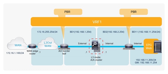
North-south firewall cluster integration
Some important deployment considerations for the model shown in the figure above are the following:
● From the point of view of the PBR policy, it is required only to specify a single MAC/IP entry representing the logical single firewall service offered by the active/active cluster. The anycast service deployed in the local pod where the PBR policy is applied will always be selected. If all the local firewall cluster nodes failed, remote nodes will start being used instead.
● The logical diagram shown in the figure above highlights the deployment of the firewall in two-arms mode (that is, two interfaces, each connected to a separate Bridge Domain). An alternative, and recommended, approach consists in deploying the firewall in “one-arm” mode. With this model, the firewall has a single interface connected to a “service Bridge Domain”) in the Cisco ACI fabric. The main advantage of such an approach is the simplification of the routing configuration on the firewall, where a simple default route pointing to the anycast gateway IP address of the service Bridge Domain) is all that is needed to ensure communication with the rest of the infrastructure.
Figure 49 shows the inbound traffic scenario where the Multi-Pod fabric is connected to the external Layer 3 domain by leveraging separate border leaf L3Out connections deployed in different pods. This is the worst-case scenario behavior, when traffic enters the “wrong” pod and needs to hairpin across the IPN to reach the destination leaf node where the PBR policy can be applied to redirect traffic to the local anycast service.
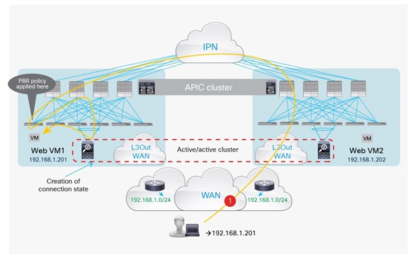
Sub-optimal Inbound traffic path
Figure 50 highlights, instead, the outbound traffic flow: the PBR policy is applied to the same compute leaf, and this leads to selecting the same local anycast service before sending the traffic to the external Layer 3 domain via the local L3Out connection.
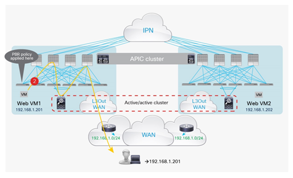
The behavior depicted above for inbound flows assumes that the PBR policy is not applied on the Border Leaf nodes receiving traffic from the external network. This is usually the case with the default VRF configuration specifying that policy enforcement for inbound flows must always be applied on the compute leaf node where the destination endpoint is connected. If, for whatever reason, that was not the case, the difference would be that for the inbound traffic path the PBR policy would redirect the traffic to the anycast service deployed in Pod2 (Figure 51).
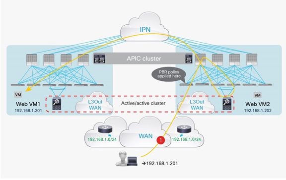
Application of PBR policy on the border leaf nodes for inbound traffic flows
For the outbound flow, the PBR policy would instead be applied on the compute leaf node, which would select the local anycast service in Pod1. This, however, does not represent an issue, as the intra-cluster redirection functionality would take care of sending the traffic through the firewall node in Pod2 holding the connection state for that specific communication.
Use of intra-cluster redirection for outbound flows
The north-south traffic flows could be optimized and the traffic hair-pinning across the IPN removed when leveraging the capability of advertising host-route information into the WAN. As previously mentioned, the capability of advertising host routes out of an L3Out connection established on the ACI border leaf nodes is supported from Cisco ACI release 4.0.
Inbound traffic optimization leveraging host-route advertisement on the border leaf nodes
For previous releases, host-route advertisement support is only possible when deploying GOLF L3Outs, as in the model shown in Figure 54.
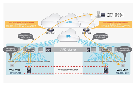
Optimized inbound traffic flows with GOLF L3Outs
Note: Both the scenarios in the previous two figures focus on the inbound traffic path. The outbound flows are equally optimized (always leveraging the L3Out connections local to the pod), essentially removing the need for any traffic hair-pinning across the IPN.
East-west firewall integration use case
The logical diagram representing the use of service graph with PBR for east-west communication is shown in Figure 55.
Use of PBR for east-west traffic flows with firewall cluster
The same deployment considerations previously discussed for the north-south use case remain valid here. Additionally, it is worth highlighting how the east-west communication can be achieved leveraging service graph with PBR in both scenarios where the EPGs communicating are part of the same VRF (as shown in the example above) or part of different VRFs. In the latter scenario, the firewall cluster could be deployed with the interface(s) connected to one of the two endpoint VRFs, but not in a third separate VRF.
For the intra-VRF communication use case, the PBR policy is usually applied on the inbound leaf where the endpoint sourcing the traffic is connected. As a consequence, for web-to-app communication, the behavior is identical to the one already shown in Figure 51 and Figure 52, and the use of intra-cluster redirection ensures successful communication between endpoints independently of where they are connected.
For the inter-VRF scenario, the PBR policy is instead always applied on the consumer VRF.
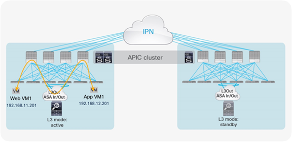
Independent active-standby firewalls pair in each pod
The last service node High-Availability (HA) deployment option uses a separate active-standby service node pair in each pod, as shown in Figure 56.
Active-standby service node pair in each pod
The deployment of independent service nodes across pods raises an operational concern about how to maintain policy configuration consistency across them. In the specific example of Cisco’s own branded firewalls, some options are available:
● Cisco Security Manager for ASA appliances: For more information, see https://www.cisco.com/c/en/us/products/security/security-manager/index.html.
● Cisco Firepower Management Center (FMC) for Cisco Firepower Next-Generation Firewall (NGFW) devices: For more information, see https://www.cisco.com/c/en/us/products/security/firesight-management-center/index.html?stickynav=1.
The critical requirement for this deployment option is that you must avoid creating an asymmetric traffic path for the two legs of each traffic flow, because doing so would cause communication drops due to the stateful nature of the firewall devices (state information cannot be replicated across independent pairs of service nodes). A solution is therefore required to keep both directions of traffic flowing through the same active service node.
The following sections discuss the supported deployment options in more detail. Before going more into those details, it is important to clarify how the design considerations in this section apply also to the specific scenario of Cisco ASA cluster deployment in “individual interface” mode. Differently from the ASA/FTD clustering model described in the previous section (“split spanned EtherChannel” mode), in “individual interface” mode each firewall node belonging to the cluster uses a unique MAC/IP combination. From a connectivity perspective, it is thus like having separate firewall instances, as shown in Figure 57. It is also worth noticing how the same considerations may apply to third-party firewall clustering solutions that behave like the Cisco ASA cluster in “individual interface” mode.
Note: “Individual interface” mode is only supported on Cisco ASA appliances and not on the newer Cisco Firepower Threat Defense (FTD) firewalls. For more information please refer to the link: https://www.cisco.com/c/en/us/td/docs/security/asa/asa95/configuration/general/asa-95-general-config/ha-cluster.pdf
Option 1: Routed firewall with L3Out peering
North-south perimeter service node integration use case
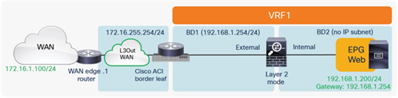
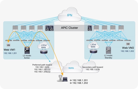
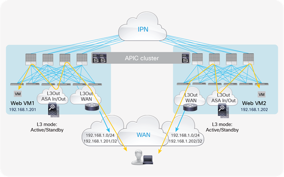
The model for north-south routed firewall insertion with L3Out peering is shown in Figure 57.
North-south routed firewall design with L3Out peering
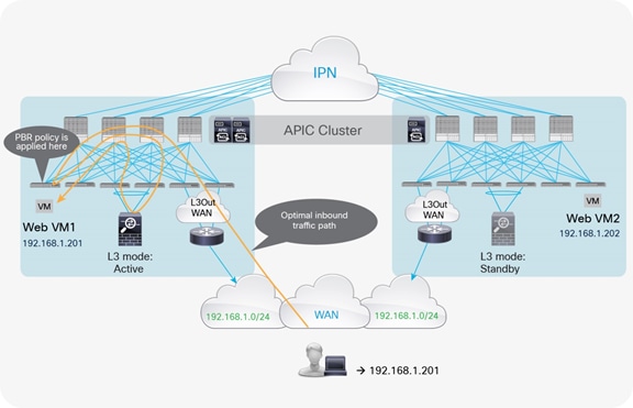
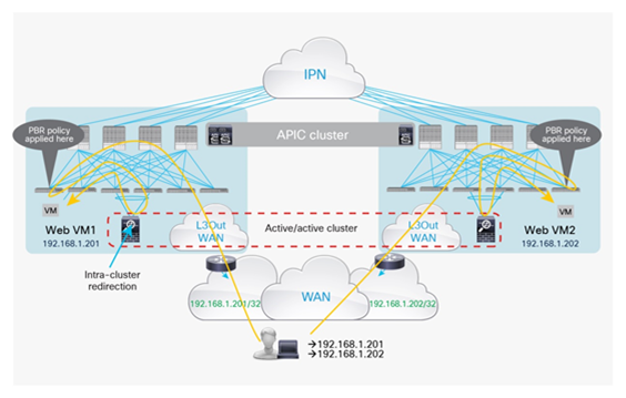
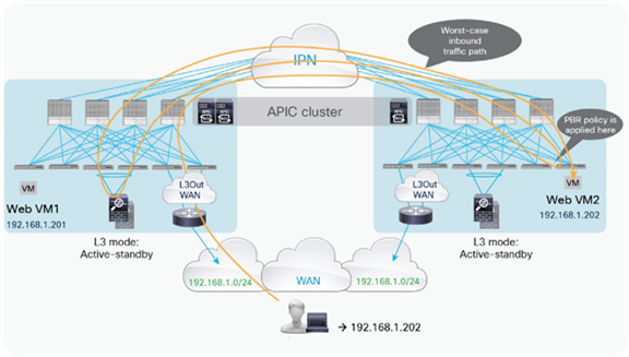
With the default configuration, if the border leaf nodes receive the traffic coming from the external network domain, destined to endpoints connected in different pods, the configuration could lose symmetry. Figure 58 shows an example of this scenario: traffic destined for 192.168.1.202 deployed in Pod2 is received on the border leaf nodes in Pod1. The VRF1 routing table has two equal-cost routes to 192.168.1.0/24: through 192.168.3.1 (HA-pair1) and through 192.168.3.2 (HA-pair2). Leaf1 in Pod1 prefers 192.168.3.1 by default because this route is local, so traffic goes to HA-pair1 in Pod1. Then traffic crosses the IPN to reach the destination endpoint in Pod2.
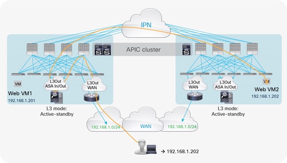
Traffic path example with traditional L3Out (inbound)
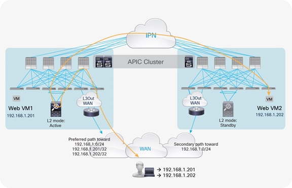
However, return traffic from 192.168.1.202 goes to the leaf in Pod2, which then selects HA-pair2 (192.168.2.2) as the next hop to the external client. HA-pair2 does not have a previously established entry in the connection table, so the firewall drops the traffic (Figure 59).
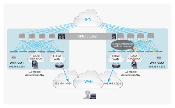
Asymmetric traffic path example with traditional L3Out (outbound)
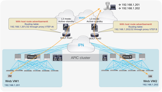
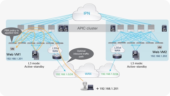
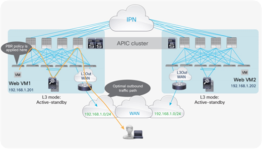
As a consequence, when deploying independent active-standby high-availability pairs in separate pods, it is critical to ensure that inbound traffic is always delivered to the “right pod,” meaning to the pod where the destination endpoint is connected. This can be achieved by leveraging more granular host route advertisement into the WAN, as shown in Figure 60 below.
Note: The same considerations apply if the Layer 3 firewall were to be connected between the ACI border leaf nodes and the external routers.
Symmetric inbound/outbound traffic path with host routes advertisement
The behavior highlighted above is supported on border leaf L3Outs starting from Cisco ACI release 4.0.
Note: Host route advertisement must also be enabled on the firewall node and on the WAN edge router connected to the L3out WAN.
Prior to Cisco ACI Release 4.0, in the scenario shown above, where the firewall is connected to the Cisco ACI fabric with an L3Out connection, the use of GOLF for L3Out connectivity toward the external domain would not help. You would not be able to send L3Out information to the WAN because of the use of traditional L3Out connections, which does not support host route advertisement prior to Cisco ACI Release 4.0, to the firewall nodes (as previously discussed in the scenario in which active-standby firewalls are stretched across pods).
The only possibility of combining the deployment of independent pairs of firewalls in each pod with an L3Out GOLF connection consists in connecting the firewall outside of the Cisco ACI fabric and north of the GOLF routers, as shown in Figure 61.
Routed firewall pairs connected north of the GOLF routers
Notice that in this model the firewall is deployed outside the Cisco ACI fabric. North-south flows are forced through the firewall by the Layer 3 lookup and forwarding processes, and ingress and egress traffic paths are optimized by the GOLF functions. This model applies well to cases in which perimeter firewalls protect the data center fabric from the Internet. In such cases, firewalls can easily be connected between the GOLF routers and the service provider devices.
In a scenario in which GOLF is used to extend VRF connectivity to the WAN, the GOLF router commonly is deployed as a Multiprotocol Label Switching (MPLS) provider edge device. In such a case, you can connect the routed firewall in two-arm mode, as shown in Figure 62.
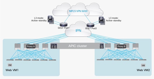
Two-arm connection between the touted firewalls and the GOLF router
Depending on the specific GOLF router deployed, north-south traffic can be enforced through the firewall using a VRF sandwich design (Cisco ASR 9000 or 1000 Series or Cisco Nexus 7000 Series Switches) or a Virtual Device Context (VDC) sandwich design (Cisco Nexus 7000 Series Switches). Figure 63 shows the two approaches.
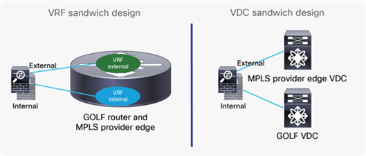
VRF sandwich design and VDC sandwich design
Notice that the option above could support also firewalls deployed in Layer 2 (transparent) mode. The firewalls must always be connected north of the GOLF routers to be able to apply security policies on the original traffic. If, in fact, they were connected between the spines and the GOLF router, they would only be capable of permitting (or denying) VXLAN encapsulated traffic without having visibility into the original packet headers and payload.
Option 2: Routed firewall with symmetric PBR
The Cisco ACI PBR can associate multiple instances of service nodes with the same PBR policy and can load-balance different traffic flows across those nodes. Ingress and egress traffic flows can then be redirected to the same PBR node, using the symmetric PBR function. Note the following considerations for the deployment of symmetric PBR:
● Symmetric PBR is supported only with the unmanaged-mode service graph.
● Symmetric PBR is supported only on the Cisco Nexus 9000 Series EX platform (and newer) ACI leaf switches: for example, the Cisco Nexus 93180YC-EX and 93108TC-EX Switches.
Note: Symmetric PBR is not supported with the managed-mode service graph because the same service graph deployment cannot push separate configurations to different active-standby pairs. For symmetric PBR, such a configuration is required because each active-standby pair uses a unique IP address, as shown earlier in Figure 58.
North-south perimeter service node integration use case
Figure 64 shows the Cisco ACI network design example for north-south routed firewall insertion with symmetric PBR. As with the use of PBR discussed in the previous section for active/standby firewall nodes, you don’t need to use a VRF sandwich with L3Out peering. The only difference is that in this case you have multiple PBR nodes, which can be represented by multiple high-availability pairs deployed in separate pods.
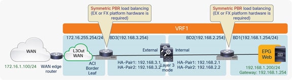
North-south routed firewall design with symmetric PBR
Note: The firewall nodes can be connected in “two-arms mode” (inside and outside interfaces connected to separate BDs), or in “one-arm mode” with a single interface connected to a service BD. The “one-arm” configuration mandates the firewall capability of receiving and sending traffic via the same interface, and greatly simplifies the static routing configuration required on the firewall (basically, reduced to a 0.0.0.0/0 route pointing to the anycast gateway IP address of the service BD).
Traditional L3Out on border leaf nodes for WAN connectivity
Depending on the configuration of metrics, incoming traffic from the external Layer 3 domain will be steered to the border leaf nodes in one of the pods. Then traffic will be sent to the leaf nodes connected to the destination endpoint and there redirected to one of the active service nodes specified in the PBR policy (based on the hashing decision). Finally, the traffic will reach the destination. Because symmetric PBR load-balances traffic based on hashing, traffic may not necessarily be sent to the local high-availability pair but may instead be redirected to the high-availability pair in a different pod.
Note: Symmetric PBR uses the source and destination IP addresses and the protocol type for hashing by default. From Cisco ACI release 3.1, it is possible to configure the specific fields to be used to calculate the hash (source-IP only, destination-IP only, or the default behavior).
In the best-case scenario, in which the destination endpoint and the selected PBR node are in the same pod where ingress traffic is received, the traffic does not need to be hair-pinned across the IPN. In this case, the path of the flow is optimal and contained inside the same pod, as shown in Figure 65.
Example of optimal inbound traffic path with PBR and traditional L3Out (inbound)
Note: The example in Figure 65 shows the case in which the border leaf nodes do not apply policy. Hence, the PBR policy is applied on the destination leaf on which the destination endpoint is located. For more information on where the PBR policy is applied, please refer to Table 2, above.
For the return traffic, because the leaf where the internal endpoint is connected knows the source and destination EPG class IDs, the PBR policy can be applied directly on the leaf. The traffic will then be redirected to the same PBR node used for the ingress flow (because of the symmetric PBR behavior) and will go back to the external network domain (Figure 66).
Example of optimal outbound traffic path with PBR and traditional L3Out (outbound)
Figure 67 shows the worst-case scenario, in which the PBR hashing selects a firewall node connected to a remote pod. Traffic from the external domain and destined for web VM2 is received on the border leaf nodes in Pod1 and is sent through the spine to the destination leaf on which the destination endpoint is located. The PBR policy is then applied on the destination leaf and, based on hashing, the PBR node in Pod1 is selected. Traffic must finally come back from the PBR node in Pod1 to reach the destination endpoint in Pod2. The end result is that, for this ingress flow, the traffic must hair-pin three times across the IPN.
Example of traffic hair-pinning with PBR and traditional L3Out (inbound)
The situation is a bit better for the return traffic because the destination leaf knows the source and destination EPG-class IDs, so it will send the traffic directly back to the previously selected firewall node, reducing the amount of traffic hair-pinning (Figure 68).

Example of traffic hair-pinning with PBR and traditional L3Out (outbound)
The suboptimal traffic behavior shown in the previous figures can be avoided by combining the use of host route advertisement from the Cisco ACI border leaf nodes (available from Cisco ACI release 4.0) with a functionality that is named “location-based PBR” (available since Cisco ACI release 3.1).
With location-based PBR, you can avoid traffic hair-pinning across the IPN because the destination leaf on which the endpoint is located will preferably select the local service node.
Figure 69 shows an example. The destination is 192.168.1.201 in Pod1, and because of the host route advertisement function, traffic originating from an external client can be selectively steered to Pod1 and reach the destination leaf on which the 192.168.1.201 endpoint is located. The destination leaf in Pod1 then selects the local PBR node, which sends traffic back to the destination. Similar behavior is achieved for traffic destined for the endpoint 192.168.1.202 in Pod2.
Note: Location-based PBR requires Cisco Nexus 9000 Series EX and FX platform service leaf switches.
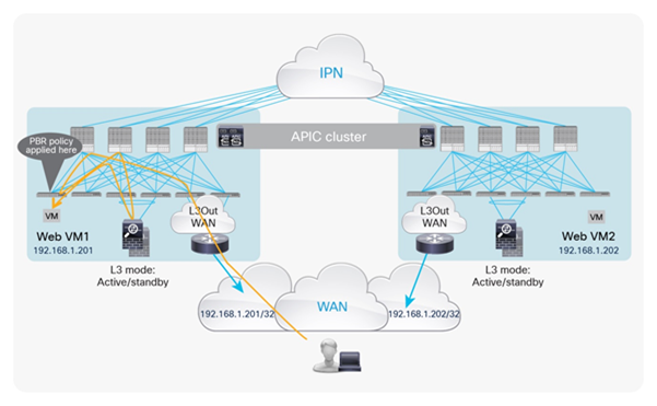
Location-based PBR with host route advertisement on the ACI border leaf nodes (inbound)
For return traffic, the destination leaf applies the PBR policy and selects the same local PBR node. Then traffic goes back to the external network domain via the L3Out connection defined on the local border leaf nodes (the default behavior with Cisco ACI Multi-Pod).
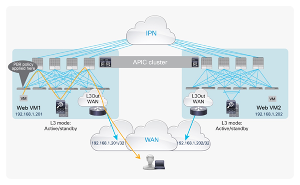
Location-based PBR with host route advertisement on the ACI border leaf nodes (outbound)
To achieve a resilient and easily deployable solution, an additional function is required with location-based PBR to detect a scenario in which all the local PBR nodes have failed. PBR hashing then can begin selecting a service node in a remote pod. This function requires a mechanism to track the availability of a PBR node from the Cisco ACI fabric.
Figure 71 shows such a mechanism (available since Cisco ACI release 3.1). When the Cisco ACI leaf nodes in Pod1 detect the failure of the local service node, the hashing function starts selecting a service node located in a remote pod. This process causes traffic hair-pinning across the IPN, but it prevents traffic from becoming black-holed.
Note: Since the connection state is not synced between the independent pairs of firewalls deployed across pods, long-lived traffic flows originally flowing through the failed firewall in Pod1 will have to be re-established by way of the firewall in the remote pod. A similar situation could happen without failure if a VM moves to a different pod.
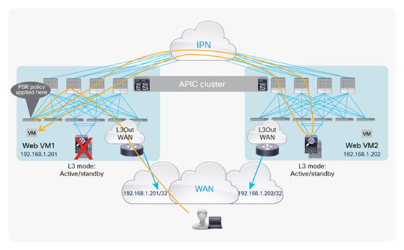
Location-based PBR with tracking
Figure 72 shows how tracking works. The service leaf on which the PBR node is located periodically sends a keep-alive message to the local node and then announces the availability information to all the other leaf switches through a fabric-wide broadcast message. This process informs all the leaf nodes that they can still use that specific node when applying the PBR policy locally.
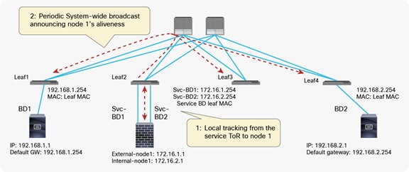
Tracking behavior
GOLF L3Out for WAN connectivity
Similarly to what was described in the previous section, the host route advertisement provided by GOLF helps optimize traffic flow between the external network domain and the destination leaf node on which the destination endpoint is located. Combining that with location-based PBR with tracking allows optimization of the inbound traffic path, as highlighted in Figure 73.
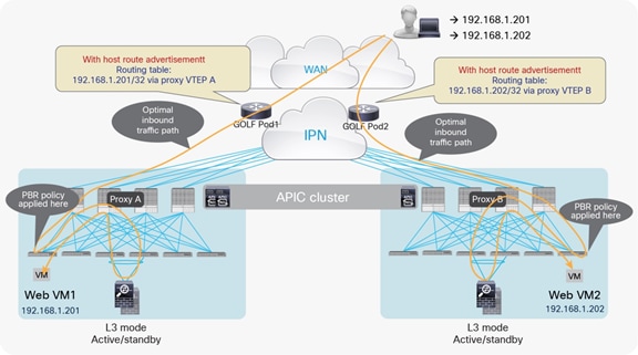
Location-based PBR with GOLF (inbound)
For return traffic, the destination leaf applies the PBR policy and selects the same local PBR node. Then traffic has to go back to the external network domain, and you can accordingly tune the MP-BGP EVPN peering between the spines and the GOLF routers to help ensure that the local GOLF devices are always preferred (Figure 74).
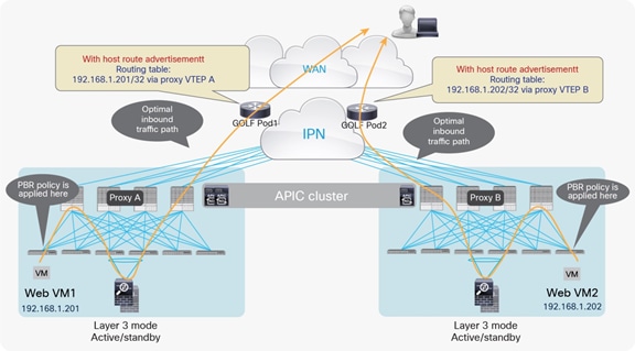
Location-based PBR with GOLF (outbound)
The use of the tracking mechanism ensures the use of remote firewall services in the rare scenario where all of the local firewall nodes fail (Figure 75).
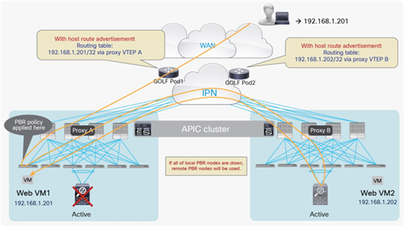
Location-based PBR with GOLF and tracking
East-west service node integration use case
Figure 76 shows the typical Cisco ACI network design for east-west routed firewall insertion with symmetric PBR. This design is similar to that for the north-south firewall use case previously discussed.
You can use only an unmanaged-mode service graph for this design because, as explained in the section discussing the north-south design, the same service graph deployment can’t push separate configurations to different active-standby pairs. For symmetric PBR, this capability is required because each active-standby pair uses a unique IP address.
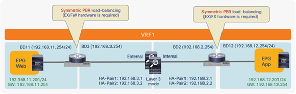
East-west routed firewall design
If the source endpoint and the destination endpoints are in the same pod and the PBR hashing function selects the service node in the same pod, a given traffic flow remains contained within the pod. However, because the hashing result changes with each flow, traffic hair-pinning cannot be eliminated in this case (Figure 77).
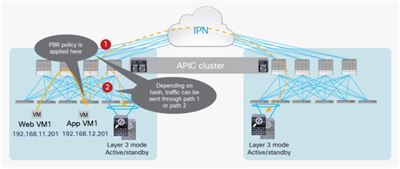
Traffic hashing to service nodes across pods
The use of location-based PBR, which drastically reduces traffic hair-pinning in the north-south case, is not supported for some cases such as L3Out-to-L3Out traffic flow, and east-west traffic flows when the provider and consumer EPGs are part of the same VRF. The reason is that in some scenarios the PBR policy may be applied on different leaf nodes for incoming and return traffic, and this behavior may lead to loss of traffic symmetry. This situation occurs, for example, if other contracts (not using PBR) are in place between the same pair of EPGs, as this causes the provider leaf to learn endpoint information for the consumer EPG. For more information about where the PBR policy is applied, refer to Table 2.
Figure 78 shows an example in which web and application virtual machines are deployed in separate pods. For communication from the web to the application, the PBR policy is applied in Pod1 on the leaf to which the web virtual machine is connected. Because of the location awareness of the PBR function, the local firewall node in Pod1 is selected, and traffic eventually reaches the destination.
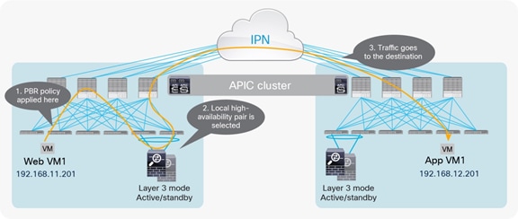
PBR policy selecting service node in Pod2 for traffic from web to application
The PBR policy for return traffic is applied on the leaf in Pod2 to which the application virtual machine is connected, and the local PBR node in Pod2 is selected. As a result of this process, traffic is dropped, because connection state information is not synchronized between the independent firewall nodes deployed across pods (Figure 79).
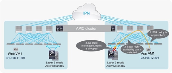
PBR policy selecting service node in Pod1 for traffic from application to web
As long as consumer and provider endpoints are in the same pod, location-based PBR will work, but because this condition cannot be guaranteed, the use of PBR with location awareness is not supported for traffic flows where policy could be applied on leaf nodes in different pods, such as intra-VRF east-west traffic flows. Please see the ACI contract guide for where policy is applied. If your firewall has a capability to take care of asymmetric traffic flow, for example connection state synchronization between independent active-standby firewall pairs, it could work with location-based PBR even though asymmetric traffic flow happens.
Note: If you want to use location-based PBR for north-south traffic inspection and use the same firewall for east-west intra-VRF traffic inspection (where location-based PBR can’t be used across pods), the firewall interfaces for north-south and east-west traffic inspection must be separated. This is because if multiple PBR policies have the same PBR destination IP in the same VRF, then all the policies must either have location-based PBR enabled or location-based PBR disabled. For example, the following configurations are not supported:
● PBR policy1 for north-south contact has PBR destination 192.168.1.1 in VRF A, location-based PBR enabled.
● PBR-policy2 for east-west contract has PBR destination 192.168.1.1 in VRF A, location-based PBR disabled.
Option 3: Routed firewall with L3Out peering and symmetric PBR
This approach uses the same routed firewall nodes for north-south by using Layer 3 lookup and for east-west traffic flows by using symmetric PBR. This approach requires Cisco APIC Release 5.2 or later to use PBR destination in an L3Out.
North-south perimeter firewall integration use case
Figure 80 shows one of the examples of Cisco ACI network design for insertion of a north-south routed firewall when the internal interfaces of the firewall nodes are connected to the Cisco ACI fabric through L3Out peering. Though it’s not illustrated in this section, the following design options are valid:
● Both the external interfaces and the internal interfaces of the firewall nodes are connected to the Cisco ACI fabric through L3Out peerings. (See Figure 57 in option 1.)
● The external interfaces of the firewall nodes are connected to the Cisco ACI fabric through an L2 bridge domain and the internal interfaces of the firewall nodes are connected to the Cisco ACI fabric through an L3Out peering.
● The external interfaces of the firewall nodes are not connected to the Cisco ACI fabric, and the internal interfaces of the firewall nodes are connected to the Cisco ACI fabric through an L3Out peering.
The difference between this approach and option 1 north-south firewall use case is that the external interfaces of the firewall nodes are not connected to the Cisco ACI fabric, which means the firewall nodes are always inserted for the traffic between the external network and the Cisco ACI fabric.
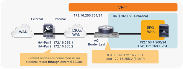
North-south routed firewall design with L3Out peering
Similar to option 1 north-south firewall use case, asymmetric traffic path consideration is applied to this approach. Please see Figures 58 to 60 in option 1.
In summary, when deploying independent active-standby high-availability pairs in separate pods, it is critical to ensure that inbound traffic is always delivered to the “right pod,” meaning to the pod where the destination endpoint is connected. This can be achieved by leveraging more granular host route advertisement into the WAN, as shown in Figure 81 below.
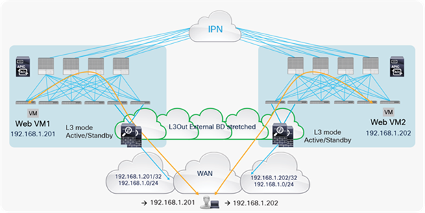
Symmetric inbound/outbound traffic path with host route advertisement
East-west firewall integration use case
Figure 82 shows a Cisco ACI network design example for east-west routed firewall insertion with symmetric PBR when the EPGs are part of the same VRF. Although this design is similar to that for option 2 east-west firewall use case, the important difference is that the firewall is connected through the external L3Out used for north-south traffic flow. This design requires an unmanaged-mode service graph and Cisco APIC Release 5.2 or later for PBR destination in an L3Out.
This approach allows the use of the same firewall for both north-south and east-west traffic inspection. The idea here is that north-south communication is always inspected by the perimeter firewall nodes and east-west communication can be inspected by the same firewall nodes if needed.
It is also possible to use the following design options:
● The use of same bridge domain subnet for the consumer and the provider EPGs.
● The use of different VRFs for the consumer and the provider EPGs. (The L3Out for the PBR node must be in either the consumer or the provider VRF.)
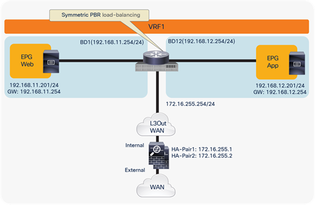
East-west routed firewall design with PBR destination in an L3Out
Similar to option 2 east-west firewall use case, traffic hair-pinning consideration is applied to this approach. Please refer to the explanations for Figures 65 to 70.
There are three different deployment models to integrate service nodes with Cisco ACI Multi-Pod fabrics:
1. Active-standby service node pair connected to separate pods
2. Active-active service node cluster stretched across separate pods
3. Independent active-standby service node pair in each pod
When considering the use of L3Out peering for active-standby nodes stretched across pods, note the following L3Out design recommendations:
● Use of separate L3Out connections across pods is not recommended, because static routing is not supported. Use of a dynamic routing option can cause a longer traffic outage.
● Use of a single L3Out connection across pods is recommended.
Use vPC to connect the service leaf nodes. This option requires Cisco ACI Release 2.1(3), 2.2(3), 2.3(1), or 3.0(1) with Cisco Nexus EX or FX platform leaf switches.
Alternatively, you can connect the firewall node to a single leaf node. This option requires Cisco ACI Release 2.1(2), 2.2(2), 2.3(1), or 3.0(1), and it is supported by all generations of leaf switches.
Remember to disable remote endpoint learning, especially if there are endpoints connected to the border leaf nodes.
From Cisco ACI release 3.2(4d), it is finally possible to deploy of a firewall cluster stretched across pods. The firewall cluster is seen as a single logical entity (owning a single pair of MAC/IP addresses) and can be integrated as default gateway for the endpoints or by leveraging PBR.
Finally, the use of PBR is the recommended approach to integrate independent firewall pairs connected to separate pods. Using the new location-based PBR function available in Cisco ACI Release 3.1, you will be able to reduce traffic hair-pinning across the IPN. Location-based PBR mandates the use of EX or FX platform leaf switches and cannot be used for firewall enforcement on east-west traffic flows.