Schema Management

Schema Design Considerations

A schema is a collection of templates, which are used for defining policies, with each template assigned to a specific tenant. There are multiple approaches you can take when it comes to creating schema and template configurations specific to your deployment use case. The following sections describe a few simple design directions you can take when deciding how to define the schemas, templates, and policies in your Multi-Site environment. Keep in mind that when designing schemas, you must consider the supported scalability limits for the number of schemas, number of templates, and number of objects per schema. Detailed information on verified scalability limits is available in the Verified Scalability Guides for Cisco APIC, Cisco ACI Multi-Site, and Cisco Nexus 9000 Series ACI-Mode Switches specific to your release.

Single Schema Deployment

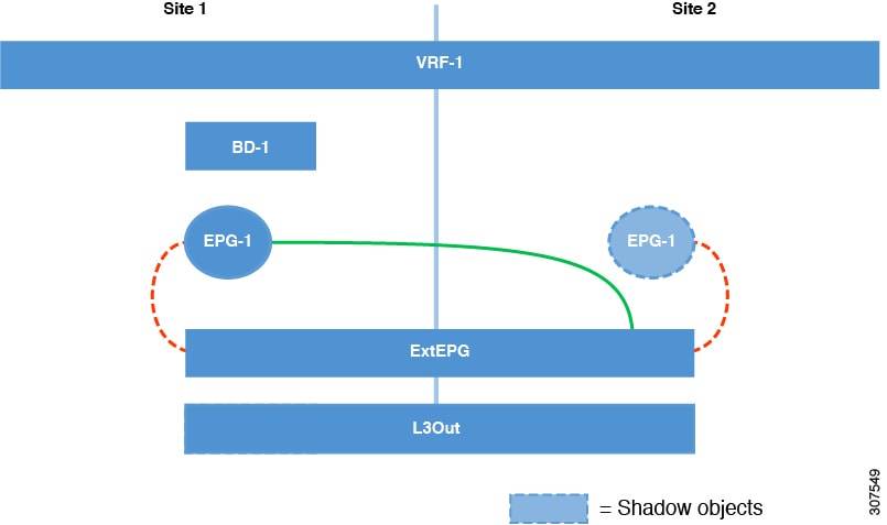
The simplest schema design approach is a single schema, single template deployment. You can create a single schema with a single template within it and adds all VRFs, Bridge Domains, EPGs, Contracts and other elements to that template. You can then create a single application profile or multiple application profiles within the template and deploy it to one or more sites.

Figure 1. Single Schema

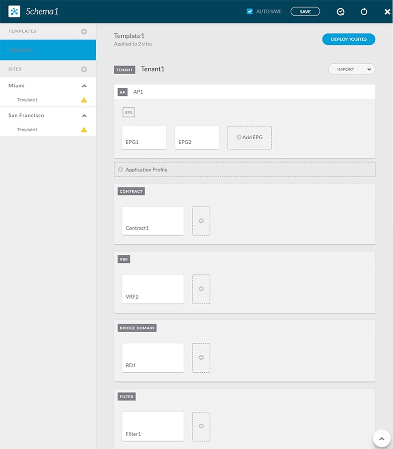
This simple approach to Multi-Site schema creation is illustrated in the figure above and allows for all objects to be readily visible within the same schema. However, the supported number of schemas or templates per schema scalability limit may make this approach unsuitable for large scale deployments, which could exceed those limits.

Multiple Schemas with Network Separation

Another approach to schema design is to separate the networking objects from the application policy configuration. Networking objects include VRFs, Bridge Domains, and subnets, while the application policy objects include EPGs, Contracts, Filters, External EPGs, and Service Graphs.

You begin by defining a schema that contains the network elements. You can choose to create a single schema that contains all the network elements or you can split them into multiple schemas based on which applications reference them or which sites the network is stretched to.

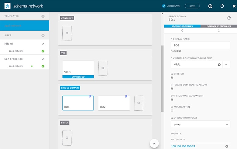
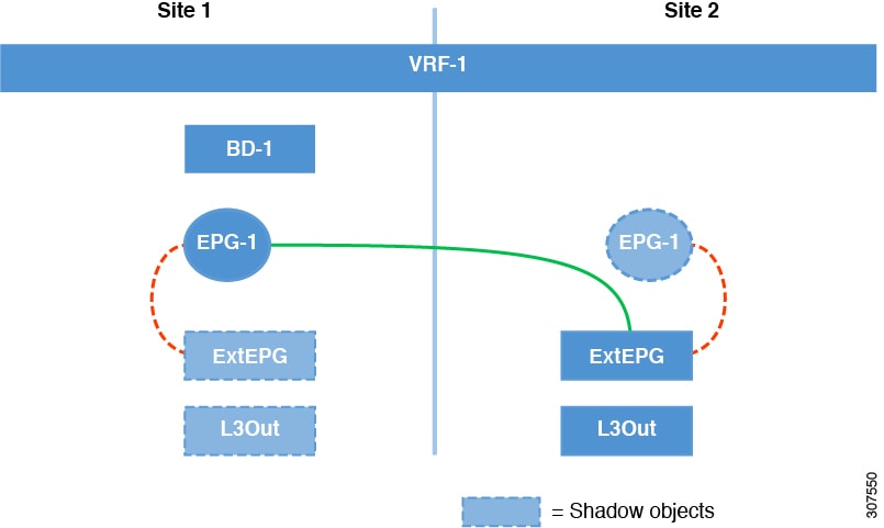
The following figure shows a single networking template configuration with VRF, BD, and subnets configured and deployed to two sites:

Figure 2. Network Schema

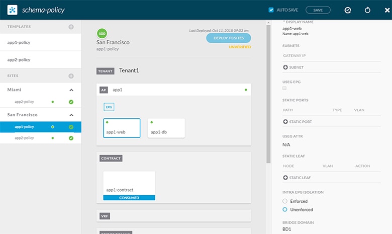
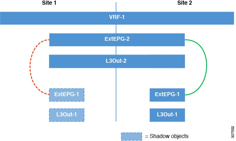
You can then define one or more separate schemas which contain each application's policy objects. This new schema can reference the network elements, such as bridge domains, defined in the previous schema. The following figure shows a policy schema that contains two application templates both of which reference the networking elements in an external schema. One of the applications is local to one site while the other is stretched across two sites:

Figure 3. Policy Schema

After creating and deploying the policy schemas and templates, the networking objects in the networking schema will display the number of external references by the policy schema elements. The object with external references will also be denoted by the ribbon icon as shown in the Network Schema figure above.

Schemas designed this way provide logical separation of networking objects from the policy objects. However, this creates additional complexity when it comes to keeping track of externally referenced objects in each schema.

Multiple Schemas Based On Object Relationships

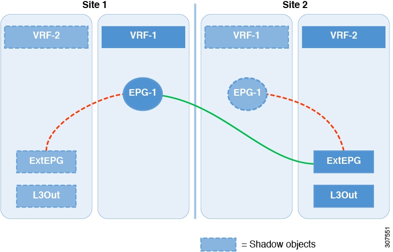
When configuring multiple schemas with shared object references, it is important to be careful when making changes to those objects. For instance, making changes to or deleting a shared networking object can impact applications in one or more sites. Because of that, you may choose to create a template around each individual site that contains only the objects used by that site and its applications, including the VRFs, BDs, EPGs, Contracts, and Filters. And create different templates containing the shared objects.

Figure 4. One Template per Site

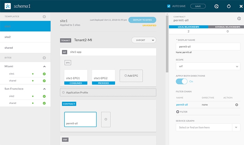
The site1 template in the above figure contains only the objects that are local to Site1 and the template is deployed to only the Miami site. Similarly, the site2 template contains only the object relevant to site2 and is deployed to the San Francisco site. Any change made to any object in either of these templates has no effect on the other one. The shared template contains any objects that are shared between the sites.

You can extend this scenario for an additional site with the following template layout:

  • Site 1 template

  • Site 2 template

  • Site 3 template

  • Site 1 and 2 shared template

  • Site 1 and 3 shared template

  • Site 2 and 3 shared template

  • All shared template

Similarly, rather than separating objects based on which site they are deployed to, you can also choose to create schemas and templates based on individual applications instead. This would allow you to easily identify each application profile and map them to schemas and sites as well as easily configure each application as local or stretched across sites.

However, as this would exceed the 5 templates per schema limit, you would have to create additional schemas to accommodate the multiple combinations. While this creates additional complexity with multiple additional schemas and templates, it provides true separation of objects based on site or application.

Schema Design for Cisco Cloud APIC Use-Cases

Cisco ACI Multi-Site supports Cisco Cloud APIC installed in the Amazon Web Services (AWS) starting with Release 2.1(1) and Microsoft Azure starting with Release 2.2(1). Each cloud deployment can be added to and managed by the Multi-Site Orchestrator as its own APIC site.

While the sections below outline generic steps required to create and manage schemas, specific use-case scenarios supported with Cloud APIC sites are detailed in the configuration examples available from the following Cloud APIC documentation landing page: https://www.cisco.com/c/en/us/support/cloud-systems-management/cloud-application-policy-infrastructure-controller/tsd-products-support-series-home.html.

Creating a Schema Template

Before you begin

  • You must have an administrative user account with full read/write privileges.

  • You must have a Cisco APIC tenant user account with read/write tenant policy privileges.

    For more information, see the User Access, Authentication, and Accounting chapter in the Cisco APIC Basic Configuration Guide.
  • You must have at least one available tenant that you want to incorporate into your site.

    For more information, refer to Adding Tenants.

Procedure


Step 1

On the Schema page, click the Add Schema button.

Step 2

On the Untitled Schema page, enter a name for the schema you intend to create.

Step 3

Access the Select A Tenant dialog box and select a tenant from the drop-down menu.

Note 

Keep in mind, the user account you're using to create a new schema must be associated with the tenant you are trying to add to it, otherwise the tenant will not be available in the drop-down menu. Associating a user account with a tenant is described in Adding Tenants.


Importing Schema Elements From APIC Sites

You can create new objects and push them out to one or more sites or you can import existing site-local objects and manage them using the Multi-Site Orchestrator. This section describes how to import one or more existing objects, while creating new objects is described later on in this document.

Procedure


Step 1

On the Schema page, select the schema where you want to import objects.

Step 2

In the left sidebar, select the template where you want to import objects.

Step 3

In the main pane click the Import button.

Step 4

Select the site from which you want to import objects.

Step 5

In the Import window that opens, select one or more objects you want to import.

Note 

The names of the objects imported into the Multi-Site Orchestrator must be unique across all sites. Importing different objects with duplicate names will cause a schema validation error and the import to fail. If you want to import objects that have the same name, you must first rename them.


Configuring an Application Profile

This section describes how to configure an Application Profile and an EPG.

Procedure


Step 1

In the schema edit view, click + Application Profile.

Step 2

In the properties pane on the right, provide a name for the application profile.

Step 3

In the AP <name> area, click + Add EPG to add an EPG.

Step 4

In the properties pane on the right, provide a name for the EPG.

Step 5

Add a contract for the EPG.

  1. Click + Contract.

  2. On the Add Contract dialog, enter the contract name and type.

  3. Click SAVE.

Step 6

From the Bridge Domain dropdown, select the bridge domain for this EPG.

If you are configuring an on-premises EPG, you must associate it with a bridge domain.

Step 7

(Optional) Click + Subnet to add a subnet to your EPG.

You may choose to configure a subnet on the EPG level rather than the bridge domain level, for example for a VRF route-leaking use-case.

  1. On the Add Subnet dialog, enter the Gateway IP address and a description for the subnet you plan to add.

  2. In the Scope field select either Private to VRF or Advertised Externally.

  3. Click the check box for Shared Between VRFs if appropriate.

  4. Click the check box for No Default SVI Gateway if appropriate.

  5. Click OK.

Step 8

(Optional) Enable microsegmentation.

If you are configuring a microsegmentation EPG (uSeg), you must provide one or more uSeg attributes for matching endpoints to the EPG.

  1. Check the uSeg EPG checkbox.

  2. Click +uSeg Attribute.

  3. Provide the Name and Type for the uSeg attribute.

  4. Based on the attribute type you have selected, provide the attribute details.

    For example, if you have selected MAC for the attribute type, provide the MAC address to identify an endpoint in this EPG.

  5. Click SAVE.

Step 9

(Optional) Enable intra-EPG isolation.

By default, endpoints in EPG can freely communicate with each other. If you would like to isolate the endpoints from each other, set the isolation mode to Enforced.

Step 10

(Optional) Enable Layer 3 multicast for the EPG.

For additional information about Layer 3 multicast, see Layer 3 Multicast

Step 11

(Optional) Enable preferred group membership for the EPG.

The Preferred Group feature allows you to include multiple EPGs within a single VRF to allow full communication between them with no need for contracts to be created. For additional information about EPG preferred group, see EPG Preferred Groups


Configuring a VRF for the Tenant

This section describes how to configure a VRF.

Procedure


Step 1

In the schema edit view, scroll down to the VRF area and click +.

Step 2

In the properties pane on the right, provide a name for the VRF.

Step 3

(Optional) Enable Layer 3 multicast for the VRF.

For additional information about Layer 3 multicast, see Layer 3 Multicast


Configuring a Bridge Domain

Procedure


Step 1

In the schema edit view, scroll down to the Bridge Domain area and click +.

Step 2

In the properties pane on the right, provide the following bridge domain details:

  • The BD name in the Display Name field.

  • The VRF in the Virtual Routing and Forwarding field.

  • If appropriate, check the L2 STRETCH checkbox.

  • If you enabled L2 STRETCH, you can choose to also enable INTERSITE BUM TRAFFIC ALLOW checkbox.

  • If you did not enable L2 STRETCH, you can choose either proxy or flood for the L2 UNKNOWN UNICAST field

Step 3

(Optional) You can choose to add one or more subnets to the bridge domain.

  1. Click + Subnet.

    An Add Subnet window opens.

  2. Enter the subnet's Gateway IP address and a description for the subnet you want to add.

  3. In the Scope field, select either Private to VRF or Advertised Externally.

  4. If appropriate, check the Shared Between VRFs checkbox.

  5. If appropriate, check the No Default SVI Gateway checkbox.

  6. If appropriate, check the Querier checkbox.

  7. Click SAVE.


Configuring a Filter for Contracts

This section describes how to configure a filter for a contract. A filter is similar to an Access Control List (ACL), it is used to filter traffic through contracts associated to EPGs.

Procedure


Step 1

In the schema edit view, scroll down to the Filter area and click +.

Step 2

In the properties pane on the right, provide a name for the filter.

Step 3

Click + Entry to add a filter entry.

In the Add Entry window that opens, provide the following information:

  1. A name for the filter entry.

  2. (Optional) A description for the filter entry..

  3. Enter the details as appropriate to filter EPG communication.

    For example, to add an entry allowing HTTPS traffic through a filter, choose the following:

    • Ethertype: IP

    • IP Protocol: TCP

    • Destination Port Range From: https

      Destination Port Range To: https

  4. Click SAVE.


Configuring a Contract

This section describes how to configure a Contract.

Procedure


Step 1

In the schema edit view, scroll down to the Contracts area and click +.

Step 2

In the properties pane on the right, provide a name for the contract.

Step 3

Choose a value for Scope using the drop-down menu.

Contract scope limits the contract's accessibility; the contract will not be applied to any consumer EPG outside the scope of the provider EPG:

  • application-profile

  • vrf

  • tenant

  • global

Step 4

Enable Apply Both Directions to apply the filter specified in the contract to either one direction or both directions.

The default setting is ON.

Step 5

Add a contract filter.

  1. Click + Filter.

  2. On the Add Filter Chain dialog, click the Name field to choose or find a filter.

  3. (Optional) Select the available directives in the Directives field.

  4. Click SAVE.

Step 6

If you disabled the Apply Both Directions option, add the second filter chain in the other direction.


Configuring an External EPG

This section describes how to configure an External EPG.

Before you begin

  • Create an L3Out in Cisco APIC on all sites where the tenant and VRF are stretched.

  • The VRF for each L3Out must be the same for all sites. Changing the VRF in APIC, after the external EPGs are deployed, resets the L3Out and requires reconfiguring and redeploying the external EPG for the site.

Procedure


Step 1

In the schema edit view, scroll down to the External EPG area and click +.

Step 2

In the properties pane on the right, select the type of External EPG and provide a name for it.

Cloud External EPGs are described in more detail in the Cisco Cloud APIC documentation.

Step 3

From the Virtual Routing & Forwarding dropdown, select the VRF to associate with this External EPG.

Step 4

Add the contracts required for the external EPGs to communicate.

Note 

If you are associating a contract with the external EPG as provider, choose contracts only from the tenant associated with the external EPG. Do not choose contracts from other tenants.

If you are associating the contract to the external EPG as consumer, you can choose any available contract.

Step 5

In the On-Prem Properties area, select an L3Out for this external EPG.


Configuring an L3Out

This section describes how to create an L3Out in the Multi-Site Orchestrator GUI. The Orchestrator then creates the L3Out on the APIC site where you deploy the template. Keep in mind that when creating an L3Out from the Orchestrator, only the L3Out container object is created in the APIC and you must still perform the full L3Out configuration (such as nodes, interfaces, routing protocols, and so on) directly in the site's APIC.

While in most cases the L3Out will be created directly at the APIC level and then associated to an external EPG that you create in the Orchestrator, it may be useful to create both here in order to directly associate the L3Out to a VRF also created in the Orchestrator.

Before you begin

Procedure


Step 1

In the schema edit view, scroll down to the L3Out area and click + to add a new L3Out.

Step 2

In the properties pane on the right, provide a display name for the L3Out and the virtual routing and forwarding (VRF) for it.


Viewing Schemas

After you have created one or more schemas, they are displayed both on the Dashboard and the Schemas page.

You can use the functionality available on these two pages to monitor the usage and the health of your schemas when they are deployed. You can also access and edit specific areas of the implemented schema policies using the Multi-Site Orchestrator GUI.

For more information about the functionality of these Multi-Site Orchestrator GUI pages, refer to Overview of the Cisco ACI Multi-Site Orchestrator GUI.

Migrating Objects Between Templates

This section describes how to move objects between templates or schemas. When moving one or more objects, the following restrictions apply:

  • Only EPG and Bridge Domain (BD) objects can be moved between templates.

  • Migrating objects to or from Cloud APIC sites is not supported.

    You can migrate objects between on-premises sites only.

  • The source and destination templates can be in different templates and schemas, but the templates must be assigned to the same tenant.

  • The destination template must have been created and assigned to at least one site.

  • If the destination template is not deployed and has no other objects, the template will be automatically deployed after the objects are migrated.

  • Once you initiate one object migration, you cannot perform another migration that involves the same source or target template. The migration is completed when the templates have been deployed to sites.

Procedure


Step 1

Log in to your Multi-Site Orchestrator GUI.

Step 2

From the left navigation menu, select Schemas.

Step 3

Click the schema that contains the objects you want to migrate.

Step 4

In the Schema view, select the Template that contains the objects you want to migrate.

Step 5

In the top right of the main pane, click Select.

This allows you to select one or more objects to migrate.

Step 6

Click each object that you want to migrate.

Selected objects will display a check mark in their top right corner.

Step 7

In the top right of the main pane, click the actions (...) icon and choose Migrate Objects.

Step 8

In the Migrate Objects window, select the destination Schema and Template where you want to move the objects.

Only the templates with at least one site attached to them will appear in the list. If you don't see your target Template in the dropdown list, cancel the wizard and assign that template to at least one site.

Step 9

Click OK and then YES to confirm that you want to move the objects.

The objects will be migrated from the source template to the destination template that you selected. When you deploy your configuration, the objects will be removed from any site where the source Template is deployed and added to the site where the destination template is deployed.

Step 10

After the migration is completed, redeploy both, the source and the destination, templates.

If the destination template is not deployed and has no other objects, the template will be automatically deployed after the objects are migrated, so you can skip this step.


Intersite L3Out

Prior to Release 2.2(1), each site managed by the Multi-Site Orchestrator required its own local L3Out configured in order to route traffic out of the fabric, which often resulted in lack of communication between endpoints in one site and a service (such a firewall, server load balancer, or mainframe) connected to the L3Out of another site.

Release 2.2(1) adds a feature that enables a number of scenarios in which endpoints located in one site are able to establish connectivity with entities, such as external network, mainframe, or service nodes, reachable through a remote L3Out.

These include the following:

  • L3Out across sites—endpoints in an application EPG in one site using an L3Out in another site.

    The L3Out and the application EPG can be in the same or different VRFs and tenants.

  • Transit L3Out across sites—endpoints in an external EPG in one site communicating with endpoints in an external EPG in another site.

    The external EPGs can be in the same or different VRFs and tenants.

  • Shared services for intersite L3Out—shared or transit L3Out between different VRFs.

Intersite L3Out Guidelines and Limitations

When configuring an intersite L3Out, you must consider the following:
  • Intersite L3Out is supported for IPv4 and IPv6.

  • If you are upgrading from a release prior to Release 2.2(1), any existing External EPG to L3Out association at the site-local level will be preserved. In addition, the Orchestrator will now support creation of an L3Out and associating it with an External EPG at the template level.

    If an L3Out is defined in a schema template, it can be used for an existing External EPG:

    • If the L3Out has the same name as the L3Out already defined in the APIC, the Orchestrator will take ownership of that L3Out but will not manage the configuration of L3Out node profiles, interface profiles, protocol settings, or route control settings.

      If you then choose to delete this L3Out from the Orchestrator, it will no longer be managed by the Orchestrator, but any previously existing L3Out configuration will be preserved in the APIC.

    • If the L3Out has a different name than the APIC defined L3Out the external EPG will be removed from the APIC defined L3Out and added to the L3Out defined in the Orchestrator. If this is the only external EPG under the APIC defined L3Out this can cause the configuration to be removed from the border leaves and can impact traffic.

  • If you choose to downgrade to a release prior to Release 2.2(1), the L3Outs created in the Orchestrator MSO will no longer exist in the template so any template-level association between External EPG and L3Out will be removed. In this case, you will need to manually re-configure the External EPG to L3Out association at the site-local level. Any site-local associations will be preserved during the downgrade.

  • You can now associate a bridge domain in one site with the L3Out in another site, however they must both be in the same tenant.

  • The Policy Control Enforcement direction for the VRF associated to the intersite L3Out must be kept configured in the default ingress mode.

  • The following scenarios are not supported with intersite L3Out and remote leaf (RL):

    • Transit routing between L3Outs deployed on RL pairs associated to separate sites

    • Endpoints connected to a RL pair associated to a site communicating with the L3Out deployed on the RL pair associated to a remote site

    • Endpoints connected to the local site communicating with the L3Out deployed on the RL pair associated to a remote site

    • Endpoints connected to a RL pair associated to a site communicating with the L3Out deployed on a remote site

  • The following other features are not supported with intersite L3Out in ACI Multi-Site:

    • Multicast receivers in a site receiving multicast from an external source via another site L3Out. Multicast received in a site from an external source is never sent to other sites. When a receiver in a site receives multicast from an external source it must be received on a local L3Out.

    • An internal multicast source sending multicast to an external receiver with PIM-SM any source multicast (ASM). An internal multicast source must be able to reach an external Rendezvous Point (RP) from a local L3Out

    • GOLF

    • Preferred Groups for External EPG

Configuring Routable TEP Addresses

Intersite L3Out requires a routable TEP address for the border leaf switches in each pod. If you already have a routable TEP pool configured, for example for another feature such as Remote Leaf, the same pool can be used. Otherwise, you can add a TEP pool in the Orchestrator GUI, as described in this section. Keep in mind, if you are adding a new TEP pool, it must not overlap with any other TEP pool in the fabric.

Procedure


Step 1

Log in to your Cisco ACI Multi-Site Orchestrator.

Step 2

From the left navigation pane, select Sites.

Step 3

In the top right of the main pane, click Configure Infra.

Step 4

In the left sidebar, select the site you want to configure.

Step 5

In the main window, click a pod in the site.

Step 6

In the right sidebar, click +Add TEP Pool.

Step 7

In the Add TEP Pool window, specify the routable TEP pool you want to configure for that site.

Note 

You must ensure that the TEP pool you are adding does not overlap with any other TEP pools or fabric addresses.

Step 8

Repeat the process for each site and pod where you plan to use intersite L3Outs.


Creating or Importing Intersite L3Out and VRF

This section describes how to create an L3Out and associate it to a VRF in the Orchestrator GUI, which will then be pushed out to the APIC site, or import an existing L3Out from one of your APIC sites. You will then associate this L3Out with an external EPG and use that external EPG to configure specific intersite L3Out use cases.


Note

The VRF you assign to the L3Out can be in any template or schema, but it must be in the same tenant as the L3Out.


Procedure


Step 1

Log in to your Cisco ACI Multi-Site Orchestrator.

Step 2

From the left navigation pane, select Schemas.

Step 3

Select the schema and then the template where you want to create or import the VRF and L3Out.

If you create the L3Out in a template that is associated to multiple sites, the L3Out will be created on all of those sites. If you create the L3Out in a template that is associated with a single site, the L3Out will be created in that site only.

Step 4

Create a new VRF and L3Out.

If you want to import an existing L3Out, skip this step.

Note 

While you can create the L3Out object in the Orchestrator and push it out to the APIC, the physical configuration of the L3Out must be done in the APIC.

  1. Scroll down to the VRF area and click the + icon to add a new VRF.

    In the right sidebar, provide the name for the VRF, for example vrf-l3out

  2. Scroll down to the L3Out area and click the + icon to add a new L3Out.

    In the right sidebar, provide the required information.

  3. Provide the name for the L3Out, for example l3out-intersite.

  4. From the Virtual Routing & Forwarding dropdown, select the VRF you created in the previous step.

Step 5

Import an existing L3Out.

If you created a new L3Out in previous step, skip this step.

  1. At the top of the main template view, click Import.

  2. Select the site from which you want to import the L3Out.

  3. In the import window's Policy Type menu, select L3Out.

  4. Check the L3Out you want to import.

  5. Click Import.


Configuring an External EPG to Use the Intersite L3Out

This section describes how to create an external EPG that will be associated to the intersite L3Out. You can then use this external EPG and contracts to configure specific use cases for endpoints in one site to use an L3Out in another site.

Before you begin

Create the L3Out and associate it with a VRF as described in Creating or Importing Intersite L3Out and VRF.

Procedure


Step 1

From the left navigation pane, select Schemas.

Step 2

Select the schema and then the template where you want to create the external EPG.

If you create the external EPG in a template that is associated to multiple sites, the external EPG will be created on all of those sites. If you create the external EPG in a template that is associated with a single site, the external EPG will be created in that site only.

Step 3

Scroll down to the External EPG area and click the + icon to add an external EPG.

In the right sidebar, provide the required information.

  1. Provide the name for the external EPG, for example eepg-intersite-l3out.

  2. From the Virtual Routing & Forwarding dropdown, select the VRF you created and used for the L3Out.

Step 4

If you want to assign the L3Out at the template level...

You can choose to configure the L3Out for the external EPG at the template level, in which case, you will not be able to set the L3Outs at the site-local level.

  1. In the left sidebar of the schema view, select the template where the external EPG is located

  2. Scroll down to the External EPG area and select the external EPG.

  3. In the right sidebar, scroll down to the L3Out dropdown and choose the intersite L3Out you created.

Step 5

If you want to assign the L3Out at the site local level...

Alternatively, you can choose to associate an L3Out with the external EPG at the site-local level.

  1. In the left sidebar of the schema view, select the site where the external EPG is deployed.

  2. Scroll down to the External EPG area and select the external EPG.

  3. In the right sidebar, scroll down to the L3Out dropdown and choose the intersite L3Out you created.

    In this case, both the APIC-managed and the Orchestrator-managed L3Outs will be available for selection. You can select either the L3Out you have created in the previous section specifically for this or pick an L3Out that exists in the site's APIC.


Creating a Contract for Intersite L3Out

This section describes how to create a filter and a contract you will use to enable traffic flow between your application EPG and the external EPG that contains the intersite L3Out.

Procedure


Step 1

Log in to your Cisco ACI Multi-Site Orchestrator.

Step 2

From the left navigation pane, select Schemas.

Step 3

Select the schema and then the template where you want to create contract and filter.

You can use the same schema and template where you created the L3Out, VRF, and the external EPG or you can choose a different schema and template.

Step 4

Create a filter for the contract.

  1. Scroll down to the Filter area and click + to create a filter.

  2. In the right sidebar, provide the Display Name for the filter.

  3. Under Entries, click +Entry to provide a filter entry.

  4. In the Add Entry window provide the details.

    The filter you create depends on your deployment and the types of traffic you want to allow.

  5. Click Save to save the filter.

Step 5

Create a contract.

  1. Scroll down to the Contracts area and click + to create a contract.

  2. In the right sidebar, provide the Display Name for the contract.

  3. From the Scope dropdown, select the appropriate scope.

    If you plan to configure shared services and the endpoints are in a different VRF from the intersite L3Out, you must select tenant for the scope. Otherwise, if both are in the same VRF, you can set the scope to vrf.

  4. You can leave the Apply Both Directions knob on.

  5. Click +Filter.

  6. From the Name dropdown menu, select the filter you created in the previous step.

  7. Click Save to add the filter to the contract.


Configuring Intersite L3Out for Application EPGs

This section describes how to configure an application EPG to use an L3Out in another site.

The figure below shows a stretched External EPG and the associated L3Out which will be created in both sites. An application EPG (epg1) is created in Site 1 and has a contract with the external EPG.

Figure 5. Stretched External EPG

The second figure below shows a similar use case but with the external EPG being deployed to only the site where the physical L3Out is located. The application EPG and the contract are configured in the same exact way to allow the traffic flow between the EPG in one site and the physical L3Out in the other.

Figure 6. Non-Stretched (Site-Local) External EPG

Regardless of whether you choose to stretch the external EPG containing L3Out or not, the communication between the application EPG and external EPG is enabled by the contract. The following steps describe how to create the application EPG and configure the contract between it and the L3Out external EPG you configured previously.

Before you begin

You need to have the following already configured:

Procedure


Step 1

Log in to your Cisco ACI Multi-Site Orchestrator.

Step 2

From the left navigation pane, select Schemas.

Step 3

Select the schema for the application EPG.

Step 4

Configure an application EPG and its bridge domain.

If you already have an EPG that will use the intersite L3Out, you can skip this step.

You can create a new or import and existing EPG and bridge domain as you typically would.

Step 5

Assign the contract to the application EPG.

  1. Select the EPG.

  2. In the right sidebar, click +Contract.

  3. Select the contract you created in previous section and its type.

Step 6

Assign the contract to the external EPG that contains the intersite L3Out.

  1. Browse to the template where the external EPG is located.

  2. Select the external EPG.

  3. In the right sidebar, click +Contract.

  4. Select the contract you created in previous section and its type.

Step 7

Assign the templates to appropriate sites.

If you are configuring the use case shown in the first figure above where the external EPG is stretched, assign the external EPG's template to all sites and the application EPG to one site.

If you are configuring the use case shown in the second figure above where the external EPG and application EPG are local to their sites, assign the external EPG's template to one site and the application EPG's template to the other.

Step 8

Associate the application EPG's bridge domain with the L3Out.

  1. In the left sidebar, under Sites, select the application EPG's template.

  2. Select the bridge domain associated with the application EPG.

  3. In the right sidebar, click +L3Out.

  4. Select the intersite L3Out you created.

Step 9

Deploy the schema.


Configuring Transit L3Out Across Sites

This section describes how to configure communication between endpoints behind an L3Out in one site and endpoints behind an L3Out in another site.

The figure below shows two L3Outs (l3out1 and l3out2) configured in different sites. Each L3Out is associated with a respective external EPG (ExtEPG1 and ExtEPG2). A contract between the two external EPGs allows communication between endpoints behind two different L3Outs in two different sites.

Figure 7. Transit L3Out

While the figure shows one of the external EPGs stretched and the other as site-local, transit L3Out supports all 3 combinations where neither external EPG is stretched, one of them is stretched, or both are stretched between sites.

Before you begin

You need to have the following already configured:

Procedure


Step 1

Log in to your Cisco ACI Multi-Site Orchestrator.

Step 2

From the left navigation pane, select Schemas.

Step 3

Assign the contract to one of the external EPGs.

  1. Select the schema and template where the external EPG is located.

  2. Select the external EPG.

  3. In the right sidebar, click +Contract.

  4. Select the contract you created in previous section and its type.

    While you can pick

Step 4

Assign the contract to the other external EPG.

  1. Select the schema and template where the external EPG is located.

  2. Browse to the template where the external EPG is located.

  3. Select the external EPG.

  4. In the right sidebar, click +Contract.

  5. Select the contract you created in previous section and its type.

Step 5

Deploy the templates to appropriate sites.

You can choose to deploy the external EPGs to one site or multiple sites. The figure above shows a example where one external EPG is stretched while the other is deployed to one site only, but you can choose any combination of stretched or site-local for the external EPGs. Since the L3Outs are in different sites, the traffic will flow through the ACI fabrics across sites.


Shared Services with Intersite L3Out

The shared services configuration for shared or transit intersite L3Out is similar to the configurations described in Configuring Intersite L3Out for Application EPGs and Configuring Transit L3Out Across Sites with a couple key differences outlined below..

Inter-VRF Shared L3Out

The figure below shows an example of inter-VRF shared L3Out scenario where an application EPG (epg-1) in site1 and vrf-1 is using site2's L3Out, which is in vrf-2.

When configuring this inter-VRF use case, you must enabled the Advertised Externally and Shared Between VRFs flags when configuring the bridge domain subnets for the application EPG.

Inter-VRF Transit L3Out

And the following figure shows an example of inter-VRF transit L3Out scenario where two external EPGs with two different L3Outs located in two different VRFs are configured with a contract.

When configuring this inter-VRF use case, you must enabled the Shared Route Control Subnet, Shared Security Import Subnet, and Aggregate Shared Routes flags when configuring the subnets for the external EPG.

EPG Preferred Groups

By default, Multi-Site architecture allows communication between EPGs only if a contract is configured between them. If there is no contract between the EPGs, any inter-EPG communication is explicitly disabled. The Preferred Group feature allows you to specify a set of EPGs that are part of the same VRF to allow full communication between them with no need for contracts to be created.

Preferred Group Vs Contracts

There are two types of policy enforcements available for EPGs in a VRF which is stretched to multiple sites with a contract preferred group configured:

  • Included EPGs – Any EPG that is a member of a preferred group can freely communicate with all other EPGs in the group without any contracts. The communication is based on the source-any-destination-any-permit default rule and appropriate Multi-Site translations.

  • Excluded EPGs – EPGs that are not members of preferred groups continue to require contracts to communicate with each other. Otherwise, the default source-any-destination-any-deny rule applies.

The contract preferred group feature allows for greater control and ease of configuration of communication between EPGs across sites in a stretched VRF context. If two or more EPGs in the stretched VRF require open communication while others must have only limited communication, you can configure a combination of a contract preferred group and contracts with filters to control the inter-EPG communication. EPGs that are excluded from the preferred group can only communicate with other EPGs if there is a contract in place to override the source-any-destination-any-deny default rule.

Stretched Vs Shadowed

If EPGs from multiple sites are configured to be part of the same contract preferred group, the Multi-Site Orchestrator creates shadows of each site's EPGs in the other sites in order to correctly translate and program the inter-site connectivity from the EPGs. Contract preferred group policy construct is then applied in each site between a real and shadow EPG for inter-EPG communication.

For example, consider a web-service EPG1 in Site1 and an app-service EPG2 in Site2 added to the contract preferred group. Then if EPG1 wants to access EPG2, it will first be translated to a shadow EPG1 in Site2 and then be able to communicate with EPG2 using the contract preferred group. Appropriate BDs are also stretched or shadowed if the EPG under it is part of a contract preferred group.

Limitations

Preferred Groups are supported for inter-site L3Out stretched external EPGs, but not for site-local L3Out external EPGs

Configuring EPGs for Preferred Group

Before you begin

You must have one or more EPGs added to a schema template.

Procedure


Step 1

Log in to your Cisco ACI Multi-Site Orchestrator.

Step 2

From the left navigation pane, select the Schemas view.

Step 3

Click the Schema that you want to change.

Step 4

Configure one or more EPGs in the schema to be part of the preferred group.

Note 

If you have an existing preferred group in any of the APICs and are planning to import the EPGs from that preferred group into Multi-Site Orchestrator, you must import all EPGs in the group. You must not have a preferred group where some EPGs are managed by the Multi-Site Orchestrator and some are managed by the local APIC.

To add or remove a single EPG:

  1. Select an EPG.

  2. In the right properties bar, check or uncheck the Include in Preferred Group checkbox.

  3. Click SAVE in the top right corner of the main window.

To add or remove multiple EPGs at once:

  1. Click SELECT in the top-right corner of the Application Profile tab.

  2. Select one or more EPGs by clicking on each one or click Select All to select all EPGs.

  3. Click ... in the top-right corner of the Application Profile tab and choose Add EPGs to Preferred Group or Remove EPGs from Preferred Group.

  4. Click SAVE in the top right corner of the main window.


What to do next

You can view the full list of EPGs that are configured to be part of the preferred group by selecting a VRF and checking the PREFERRED GROUP EPGS list in the properties sidebar on the right.

Layer 3 Multicast


Note

Layer 3 Multicast across sites is a limited availability feature. If you plan to enable this feature in your production environment, please consult Cisco for deployment planning and validation.


Cisco Multi-Site Layer 3 multicast is enabled or disabled at three levels, the VRF, the bridge domain (BD), and any EPGs that have multicast sources present.

At the top level, multicast routing must be enabled on the VRF that has any multicast-enabled BDs. On a multicast-enabled VRF, there can be a combination of multicast-enabled BDs and BDs where multicast routing is disabled. Enabling multicast routing on a VRF from the Cisco Multi-Site Orchestrator GUI enables it on the APIC sites where the VRF is stretched.

Once a VRF is enabled for multicast, the individual BDs under that VRF can be enabled for multicast routing. Configuring Layer 3 multicast on a BD enables protocol independent routing (PIM) on that BD. By default, multicast is disabled in all BDs.

When an EPG sends multicast traffic to a remote site where it is not stretched, the Multi-Site Orchestrator creates a shadow EPG on the remote site for each such EPG. This could potentially result in an increased amount of configuration changes, such as subnet routes, being pushed to the remote Top-of-Rack (TOR) switches. To alleviate this, Layer 3 multicast has to also be enabled on the individual EPGs which have multicast sources present, in which case only the configuration necessary for those EPGs is pushed to the remote sites. EPGs with multicast receivers do not require enabling Layer 3 multicast.

Multi-Site supports all of the following Layer 3 multicast source and receiver combinations:

  • Multicast sources and receivers inside ACI fabric

  • Multicast sources and receivers outside ACI fabric

  • Multicast sources inside ACI fabric with external receivers

  • Multicast receivers inside ACI fabric with external sources

Layer 3 Multicast Routing

The following is a high level overview of the Layer 3 multicast routing across sites:

  • When the multicast source is attached to ACI fabric as End Point (EP) at one site, that site's spine switch will send the multicast traffic to other sites where the source's VRF is instantiated using the Head End Replication (HREP). The multicast traffic will be sent over to other sites where VRF is stretched and multicast traffic will be pruned/forwarded at egress leaf switches based on the group membership.

  • The multicast routing solution requires external multicast router to be the Rendezvous Point (RP). Each site must point to the same RP address for a given stretched VRF. The RP must be reachable on each site via the site's local L3Out.

  • When the source is outside and the receiver is within a fabric, the receiver will pull traffic via site's local L3Out as PIM joins toward RP and source are always sent via site local L3Out.

  • Receivers in each site are expected to draw traffic from source outside the fabric via the site's local L3Out. As such, traffic coming in on L3Out on one site should not be sent to other sites. This is achieved on the spine by pruning multicast traffic from replicating into HREP tunnels.

  • All multicast traffic ingressing a TOR's L3out bridge domain from external router is remarked with a special DCSP value in the outer VXLAN header. On the Spine, that DSCP value is matched to prune all multicast traffic from replicating HREP copies into the ISN network

  • Traffic sent from one site can be sent out of any site’s L3Out.

  • When multicast is enabled on a BD and an EPG from the Multi-Site Orchestrator, all of the BD's subnets are injected into all leaf switches, including the border leaf (BL). This enable receivers attached to the leaf switches to determine the reachability of the multicast source in cases where the source BD is not present on the leaf switches. The subnet is advertised if there is a policy configured on the BL. The /32 host routes are advertised if host-based routing is configured on the BD. The BD's subnets and host routes are advertised if the L3Out policy allows a large subnet range including 0/0 and multicast is enabled on the EPG.

For additional information about multicast routing, see the IP Multicast section of the Cisco APIC Layer 3 Networking Configuration Guide.

Guidelines and Limitations

Cisco ACI Multi-Site Orchestrator cannot create the required local policies on each site, as such you must configure IGMP related policies, PIM related policies, route-maps, RPs, and L3Outs on each APIC site individually for end-to-end solution to work.

You must also ensure that DSCP policies in all fabrics are configured consistently. The DSCP packet header values must match for the multicast traffic to transit between sites.

For specific information on how to configure those settings on each site, see the Cisco APIC Layer 3 Networking Configuration Guide.

Enabling Layer 3 Multicast

The following procedure describes how to enable Layer 3 multicast on VRF, BD, and EPG using the Cisco ACI Multi-Site Orchestrator GUI.

Before you begin

Ensure you have read and followed the information described in Guidelines and Limitations.

Procedure


Step 1

Log in to your Cisco ACI Multi-Site Orchestrator.

Step 2

From the left-hand sidebar, select the Schemas view.

Step 3

Click on the Schema you want to change.

Step 4

Enable Layer 3 multicast on a VRF.

First, you enable Layer 3 multicast on a VRF that is stretched between sites.

  1. Select the VRF for which you want to enable Layer 3 multicast.

  2. In the right-hand sidebar, check the L3 Multicast checkbox.

Step 5

Enable Layer 3 multicast on a BD.

Once you have enabled L3 Multicast on a VRF, you can enable L3 multicast on a Bridge Domain (BD) level.

  1. Select the BD for which you want to enable Layer 3 multicast.

  2. In the right-hand sidebar, check the L3 Multicast checkbox.

Step 6

Enable Layer 3 multicast on an EPG.

Once you have enabled L3 Multicast on the BD, you can select EPGs which have multicast sources. You can only do that if the EPG is part of multicast-enabled BD and VRF.

  1. Select the EPG for which you want to enable Layer 3 multicast.

  2. In the right-hand sidebar, check the Intersite Multicast Source checkbox.


Shadow EPGs and BDs

When a contract exists between site-local EPGs in stretched VRF or in Shared Services use-cases where provider and consumer are in different VRFs and communicate through Tenant contracts, the EPGs and bridge domains (BDs) are mirrored on the remote sites. These mirrored objects appear as if they are deployed in each of these sites' APICs, while only actually being deployed in one of the sites. These mirrored objects are called "shadow" EPGs or BDs.

For example, if the provider site group tenant and VRF are stretched across Site 1 and Site 2, and the consumer site group tenant and VRF are stretched across Site 3 and Site 4, in the APIC GUI at Site 1, Site 2, Site 3, and Site 4, you can see both tenants and their policies. They appear with the same names as the ones that were deployed directly to each site.

You can distinguish these shadow EPGs and BDs in the APIC GUI as described below:


Note

Shadow objects should not be removed using the APIC GUI.


Procedure


Step 1

To identify a shadow EPG in a pair of EPGs with the same name, in the APIC GUI, navigate to Tenants > tenant-name > Application Profiles > ap-name > Application EPGs > epg-name > Static Ports.

A shadow EPG has no path to the static port.

Step 2

To identify a shadow BD from a pair of BDs with the same name, in the APIC GUI, navigate to Tenants > tenant-name > Networking > Bridge Domains > bd-name > Subnets > subnet-name.

The subnet for a shadow BD has No Default SVI Gateway enabled.