Tenant Routed Multicast

This chapter contains the following sections:

Tenant Routed Multicast

Cisco Application Centric Infrastructure (ACI) Tenant Routed Multicast (TRM) enables Layer 3 multicast routing in Cisco ACI tenant VRF instances. TRM supports multicast fowarding between senders and receivers within the same or different subnets. Multicast sources and receivers can be connected to the same or different leaf switches or external to the fabric using L3Out connections.

In the Cisco ACI fabric, most unicast and IPv4 multicast routing operate together on the same border leaf switches, with the IPv4 multicast protocol operating over the unicast routing protocols.

In this architecture, only the border leaf switches run the full Protocol Independent Multicast (PIM) protocol. Non-border leaf switches run PIM in a passive mode on the interfaces. They do not peer with any other PIM routers. The border leaf switches peer with other PIM routers connected to them over L3Outs and also with each other.

The following figure shows border leaf switch 1 and border leaf switch 2 connecting to router 1 and router 2 in the IPv4 multicast cloud. Each virtual routing and forwarding (VRF) instance in the fabric that requires IPv4 multicast routing will peer separately with external IPv4 multicast routers.

Figure 1. Overview of Multicast Cloud

About the Fabric Interface

The fabric interface is a virtual interface between software modules and represents the fabric for multicast routing. The interface takes the form of a tunnel interface with the tunnel destination being the VRF GIPo (Group IP outer address). For example, if a border leaf is the designated forwarder responsible for forwarding traffic for a group, then the fabric interface would be in the outgoing interface (OIF) list for the group. There is no equivalent for the interface in hardware. The operational state of the fabric interface should follow the aggFabState published by the intermediate system-to-intermediate system (IS-IS).


Note


Each multicast-enabled VRF requires one or more border leaf switches configured with a loopback interface. You must configure a unique IPv4 loopback address on all nodes in a PIM-enabled L3Out. The Router-ID loopback or another unique loopback address can be used.


Any loopback configured for unicast routing can be reused. This loopback address must be routed from the external network and will be injected into the fabric MPBGP (Multiprotocol Border Gateway Protocol) routes for the VRF. The fabric interface source IP will be set to this loopback as the loopback interface. The following figure shows the fabric for multicast routing.

Figure 2. Fabric for Multicast routing

Enabling IPv4 Tenant Routed Multicast

Multicast is enabled or disabled at three levels, the VRF, L3 Out, and the bridge domain (BD). At the top level, multicast routing must be enabled on the VRF that has any multicast-enabled BDs. On a multicast-enabled VRF, there can be a combination of multicast routing-enabled BDs and BDs where multicast routing is disabled. BD with multicast-routing disabled will not show on VRF multicast panel. L3 Out with multicast routing-enabled will show up on the panel as well, but any BD that has multicast routing-enabled will always be a part of a VRF that has multicast routing-enabled.

Multicast Routing is not supported on the leaf switches such as Cisco Nexus 93128TX, 9396PX, and 9396TX. All the multicast routing and any multicast-enabled VRF should be deployed only on the switches with -EX in their product IDs such as Cisco Nexus 93108TC-EX and 93180YC-EX.


Note


Layer 3 Out ports and sub-interfaces are supported while external SVIs are not supported. Since external SVIs are not supported, PIM cannot be enabled in L3-VPC.

Allocating VRF GIPo

VRF GIPo is allocated implicitly based on configuration. There will be one GIPo for the VRF and one GIPo for every BD under that VRF. Additionally, any given GIPo might be shared between multiple BDs or multiple VRFs, but not a combination of VRFs and BDs. APIC will be required to ascertain this. In order to handle the VRF GIPo in addition to the BD GIPos already handled and build GIPo trees for them, IS-IS is modified.

All multicast traffic for PIM enabled BDs will be forwarded using the VRF GIPo. This includes both Layer 2 and Layer 3 IP multicast. Any broadcast or unicast flood traffic on the multicast enabled BDs will continue to use the BD GIPo. Non-IP multicast enabled BDs will use the BD GIPo for all multicast, broadcast, and unicast flood traffic.

The APIC GUI will display a GIPo multicast address for all BDs and VRFs. The address displayed is always a /28 network address (the last four bits are zero). When the VXLAN packet is sent in the fabric, the destination multicast GIPo address will be an address within this /28 block and is used to select one of 16 FTAG trees. This achieves load balancing of multicast traffic across the fabric.

Table 1. GIPo Usage

Traffic

Non-MC Routing-enabled BD

MC Routing-enabled BD

Broadcast

BD GIPo

BD GIPo

Unknown Unicast Flood

BD GIPo

BD GIPo

Multicast

BD GIPo

VRF GIPo

Multiple Border Leaf Switches as Designated Forwarder

When there are multiple border leaf (BL) switches in the fabric doing multicast routing, only one of the border leafs is selected as the designated forwarder for attracting traffic from the external multicast network and forwarding it to the fabric. This prevents multiple copies of the traffic and it balances the load across the multiple BL switches.

This is done by striping ownership for groups across the available BL switches, as a function of the group address and the VRF virtual network ID (VNID). A BL that is responsible for a group sends PIM joins to the external network to attract traffic into the fabric on behalf of receivers in the fabric.

Each BL in the fabric has a view of all the other active BL switches in the fabric in that VRF. So each of the BL switches can independently stripe the groups consistently. Each BL monitors PIM neighbor relations on the fabric interface to derive the list of active BL switches. When a BL switch is removed or discovered, the groups are re-striped across the remaining active BL switches. The striping is similar to the method used for hashing the GIPos to external links in multi-pod deployment, so that the group-to-BL mapping is sticky and results in fewer changes on up or down.

Figure 3. Model for Multiple Border Leafs as Designated Forwarder

PIM Designated Router Election

For Layer 3 multicast on ACI fabric, the PIM DR (designated router) mechanism for different interface types is as follows:

  • PIM-enabled L3 Out interfaces: Follows standard PIM DR mechanism on these interface types.

  • Fabric interface: DR election on this interface is not of much significance as the DR functionality is determined by the striping. PIM DR election continues unaltered on this interface.
  • Multicast routing-enabled Pervasive BDs: The pervasive BDs in the fabric are all stubs as far as multicast routing is concerned. Hence, on all the leaf switches, the SVI interfaces for pervasive BDs including vPC, are considered DR on the segment.

Non-Border Leaf Switch Behavior

On the non-border leaf switches, PIM runs in passive mode on the fabric interface and on the pervasive BD SVIs. PIM is in a new passive-probe mode where it sends only hellos. PIM neighbors are not expected on these pervasive BD SVIs. It is desirable to raise a fault when a PIM hello is heard from a router on a pervasive BD. PIM, on the non-border leaf switches, does not send any PIM protocol packets except for hellos on pervasive BDs and source register packets on the fabric interface.

At the same time, PIM will receive and process the following PIM packets on the fabric interface:

  • PIM Hellos: This is used to track the active BL list on the fabric interface and on the pervasive BDs, this is used to raise faults.

  • PIM BSR, Auto-RP advertisements: This is received on the fabric interface and is processed to glean the RP to group-range mapping.

Active Border Leaf Switch List

On every leaf switch, PIM maintains a list of active border leaf switches that is used for striping and other purposes. On the border leaf switches themselves this active border leaf list is derived from the active PIM neighbor relations. On non-border leaf switches, the list is generated by PIM using the monitored PIM Hello messages on the fabric interface. The source IP on the hello messages is the loopback IP assigned to each border leaf switch.

Overload Behavior On Bootup

When a border leaf switch gains connectivity to the fabric for the first time after bootup or after losing connectivity, it is not desirable to cause the border leaf switch to be part of the active border leaf switch list till the border leaf switch has had a chance to pull the COOP repo1 information and to bring up its southbound protocol adjacencies. This can be achieved by delaying the transmission of PIM hello messages for a non-configured period of time.

First-Hop Functionality

The directly connected leaf will handle the first-hop functionality needed for PIM sparse mode.

The Last-Hop

The last-hop router is connected to the receiver and is responsible for doing a shortest-path tree (SPT) switchover in case of PIM any-source multicast (ASM). The border leaf switches will handle this functionality. The non-border leaf switches do not participate in this function.

Fast-Convergence Mode

The fabric supports a configurable fast-convergence mode where every border leaf switch with external connectivity towards the root (RP for (*,G) and source for (S, G)) pulls traffic from the external network. To prevent duplicates, only one of the BL switches forwards the traffic to the fabric. The BL that forwards the traffic for the group into the fabric is called the designated forwarder (DF) for the group. The stripe winner for the group decides on the DF. If the stripe winner has reachability to the root, then the stripe winner is also the DF. If the stripe winner does not have external connectivity to the root, then that BL chooses a DF by sending a PIM join over the fabric interface. All non-stripe winner BL switches with external reachability to the root send out PIM joins to attract traffic but continue to have the fabric interface as the RPF interface for the route. This results in the traffic reaching the BL switch on the external link, but getting dropped.

The advantage of the fast-convergence mode is that when there is a stripe owner change due to a loss of a BL switch for example, the only action needed is on the new stripe winner of programming the right Reverse Path Forwarding (RPF) interface. There is no latency incurred by joining the PIM tree from the new stripe winner. This comes at the cost of the additional bandwidth usage on the non-stripe winners' external links.

Note


Fast-convergence mode can be disabled in deployments where the cost of additional bandwidth outweighs the convergence time saving.


ACI Multicast Feature List

The following sections provide a list of ACI multicast features with comparisons to similar NX-OS features.

IGMP Features

ACI Feature Name

NX-OS Feature

Description

Allow V3 ASM

ip igmp allow-v3-asm

Allow accepting IGMP version 3 source-specific reports for multicast groups outside of the SSM range. When this feature is enabled, the switch will create an (S,G) mroute entry if it receives an IGMP version 3 report that includes both the group and source even if the group is outside of the configured SSM range. This feature is not required if hosts send (*,G) reports outside of the SSM range, or send (S,G) reports for the SSM range.

Fast Leave

ip igmp immediate-leave

Option that minimizes the leave latency of IGMPv2 group memberships on a given IGMP interface because the device does not send group-specific queries. When immediate leave is enabled, the device removes the group entry from the multicast routing table immediately upon receiving a leave message for the group. The default is disabled.

Note: Use this command only when there is one receiver behind the BD/interface for a given group

Report Link Local Groups

ip igmp report-link-local-groups

Enables sending reports for groups in 224.0.0.0/24. Reports are always sent for nonlink local groups. By default, reports are not sent for link local groups.

Group Timeout (sec)

ip igmp group-timeout

Sets the group membership timeout for IGMPv2. Values can range from 3 to 65,535 seconds. The default is 260 seconds.

Query Interval (sec)

ip igmp query-interval

Sets the frequency at which the software sends IGMP host query messages. Values can range from 1 to 18,000 seconds. The default is 125 seconds.

Query Response Interval (sec)

ip igmp query-max-response-time

Sets the response time advertised in IGMP queries. Values can range from 1 to 25 seconds. The default is 10 seconds.

Last Member Count

ip igmp last-member-query-count

Sets the number of times that the software sends an IGMP query in response to a host leave message. Values can range from 1 to 5. The default is 2.

Last Member Response Time (sec)

ip igmp last-member-query-response-time

Sets the query interval waited after sending membership reports before the software deletes the group state. Values can range from 1 to 25 seconds. The default is 1 second.

Startup Query Count

ip igmp startup-query-count

Sets the query count used when the software starts up. Values can range from 1 to 10. The default is 2.

Querier Timeout

ip igmp querier-timeout

Sets the query timeout that the software uses when deciding to take over as the querier. Values can range from 1 to 65,535 seconds. The default is 255 seconds.

Robustness Variable

ip igmp robustness-variable

Sets the robustness variable. You can use a larger value for a lossy network. Values can range from 1 to 7. The default is 2.

Version

ip igmp version <2-3>

IGMP version that is enabled on the bridge domain or interface. The IGMP version can be 2 or 3. The default is 2.

Report Policy Route Map*

ip igmp report-policy <route-map>

Access policy for IGMP reports that is based on a route-map policy. IGMP group reports will only be selected for groups allowed by the route-map

Static Report Route Map*

ip igmp static-oif

Statically binds a multicast group to the outgoing interface, which is handled by the switch hardware. If you specify only the group address, the (*, G) state is created. If you specify the source address, the (S, G) state is created. You can specify a route-map policy name that lists the group prefixes, group ranges, and source prefixes. Note A source tree is built for the (S, G) state only if you enable IGMPv3.

Maximum Multicast Entries

ip igmp state-limit

Limit the mroute states for the BD or interface that are created by IGMP reports.

Default is disabled, no limit enforced. Valid range is 1-4294967295.

Reserved Multicast Entries

ip igmp state-limit <limit> reserved <route-map>

Specifies to use the route-map policy name for the reserve policy and set the maximum number of (*, G) and (S, G) entries allowed on the interface.

State Limit Route Map*

ip igmp state-limit <limit> reserved <route-map>

Used with Reserved Multicast Entries feature

IGMP Snooping Features

ACI Feature Name

NX-OS Feature

Description

IGMP snooping admin state

[no] ipigmp snooping

Enables/disables the IGMP snooping feature. Cannot be disabled for PIM enabled bridge domains

Fast Leave

ip igmp snooping fast-leave

Option that minimizes the leave latency of IGMPv2 group memberships on a given IGMP interface because the device does not send group-specific queries. When immediate leave is enabled, the device removes the group entry from the multicast routing table immediately upon receiving a leave message for the group. The default is disabled.

Note: Use this command only when there is one receiver behind the BD/interface for a given group

Enable Querier

ip igmp snooping querier <ip address>

Enables the IP IGMP snooping querier feature on the Bridge Domain. Used along with the BD subnet Querier IP setting to configure an IGMP snooping querier for bridge domains.

Note: Should not be used with PIM enabled bridge domains. The IGMP querier function is automatically enabled for when PIM is enabled on the bridge domain.

Query Interval

ip igmp snooping query-interval

Sets the frequency at which the software sends IGMP host query messages. Values can range from 1 to 18,000 seconds. The default is 125 seconds.

Query Response Interval

ip igmp snooping query-max-response-time

Sets the response time advertised in IGMP queries. Values can range from 1 to 25 seconds. The default is 10 seconds.

Last Member Query Interval

ip igmp snooping last-member-query-interval

Sets the query interval waited after sending membership reports before the software deletes the group state. Values can range from 1 to 25 seconds. The default is 1 second.

Start Query Count

ip igmp snooping startup-query-count

Configures snooping for a number of queries sent at startup when you do not enable PIM because multicast traffic does not need to be routed. Values can range from 1 to 10. The default is 2.

Start Query Interval (sec)

ip igmp snooping startup-query-interval

Configures a snooping query interval at startup when you do not enable PIM because multicast traffic does not need to be routed. Values can range from 1 to 18,000 seconds. The default is 31 seconds

MLD Snooping Features

ACI Feature Name

NX-OS Feature

Description

MLD snooping admin state

ipv6 mld snooping

IPv6 MLD snooping feature. Default is disabled

Fast Leave

ipv6 mld snooping fast-leave

Allows you to turn on or off the fast-leave feature on a per bridge domain basis. This applies to MLDv2 hosts and is used on ports that are known to have only one host doing MLD behind that port. This command is disabled by default.

Enable Querier

ipv6 mld snooping querier

Enables or disables IPv6 MLD snooping querier processing. MLD snooping querier supports the MLD snooping in a bridge domain where PIM and MLD are not configured because the multicast traffic does not need to be routed.

Query Interval

ipv6 mld snooping query-interval

Sets the frequency at which the software sends MLD host query messages. Values can range from 1 to 18,000 seconds. The default is 125 seconds.

Query Response Interval

ipv6 mld snooping query-interval

Sets the response time advertised in MLD queries. Values can range from 1 to 25 seconds. The default is 10 seconds.

Last Member Query Interval

ipv6 mld snooping last-member-query-interval

Sets the query response time after sending membership reports before the software deletes the group state. Values can range from 1 to 25 seconds. The default is 1 second.

PIM Features (Interface Level)

ACI Feature Name

NX-OS Feature

Description

Authentication

ip pim hello-authentication ah-md5

Enables MD5 hash authentication for PIM IPv4 neighbors

Multicast Domain Boundary

ip pim border

Enables the interface to be on the border of a PIM domain so that no bootstrap, candidate-RP, or Auto-RP messages are sent or received on the interface. The default is disabled.

Passive

ip pim passive

If the passive setting is configured on an interface, it will enable the interface for IP multicast. PIM will operate on the interface in passive mode, which means that the leaf will not send PIM messages on the interface, nor will it accept PIM messages from other devices across this interface. The leaf will instead consider that it is the only PIM device on the network and thus act as the DR. IGMP operations are unaffected by this command.

Strict RFC Compliant

ip pim strict-rfc-compliant

When configured, the switch will not process joins from unknown neighbors and will not send PIM joins to unknown neighbors

Designated Router Delay (sec)

ip pimdr-delay

Delays participation in the designated router (DR) election by setting the DR priority that is advertised in PIM hello messages to 0 for a specified period. During this delay, no DR changes occur, and the current switch is given time to learn all of the multicast states on that interface. After the delay period expires, the correct DR priority is sent in the hello packets, which retriggers the DR election. Values are from 1 to 65,535. The default value is 3.

Note: This command delays participation in the DR election only upon bootup or following an IP address or interface state change. It is intended for use with multicast-access non-vPC Layer 3 interfaces only.

Designated Router Priority

ip pim dr-priority

Sets the designated router (DR) priority that is advertised in PIM hello messages. Values range from 1 to 4294967295. The default is 1.

Hello Interval (milliseconds)

ip pim hello-interval

Configures the interval at which hello messages are sent in milliseconds. The range is from 1000 to 18724286. The default is 30000.

Join-Prune Interval Policy (seconds)

ip pim jp-interval

Interval for sending PIM join and prune messages in seconds. Valid range is from 60 to 65520. Value must be divisible by 60. The default value is 60.

Interface-level Inbound Join-Prune Filter Policy*

ip pimjp-policy

Enables inbound join-prune messages to be filtered based on a route-map policy where you can specify group, group and source, or group and RP addresses. The default is no filtering of join-prune messages.

Interface-level Outbound Join-Prune Filter Policy*

ip pim jp-policy

Enables outbound join-prune messages to be filtered based on a route-map policy where you can specify group, group and source, or group and RP addresses. The default is no filtering of join-prune messages.

Interface-level Neighbor Filter Policy*

ip pim neighbor-policy

Controls which PIM neighbors to become adjacent to based on route-map policy where you specify the source address/address range of the permitted PIM neighbors

PIM Features (VRF Level)

ACI Feature Name

NX-OS Feature

Description

Static RP

ippimrp-address

Configures a PIM static RP address for a multicast group range. You can specify an optional route-map policy that lists multicast group ranges for the static RP. If no route-map is configured, the static RP will apply to all multicast group ranges excluding any configured SSM group ranges.

The mode is ASM.

Fabric RP

n/a

Configures an anycast RP on all multicast enabled border leaf switches in the fabric. Anycast RP is implemented using PIM anycast RP. You can specify an optional route-map policy that lists multicast group ranges for the static RP.

Auto-RP Forward Auto-RP Updates

ip pim auto-rp forward

Enables the forwarding of Auto-RP messages. The default is disabled.

Auto-RP Listen to Auto-RP Updates

ip pim auto-rp listen

Enables the listening for Auto-RP messages. The default is disabled.

Auto-RP MA Filter *

ip pim auto-rp mapping-agent-policy

Enables Auto-RP discover messages to be filtered by the border leaf based on a route-map policy where you can specify mapping agent source addresses. This feature is used when the border leaf is configured to listen for Auto-RP messages. The default is no filtering of Auto-RP messages.

BSR Forward BSR Updates

ippimbsr forward

Enables forwarding of BSR messages. The default is disabled, which means that the leaf does not forward BSR messages.

BSR Listen to BRS Updates

ip pim bsr listen

Enables listening for BSR messages. The default is disabled, which means that the leaf does not listen for BSR messages.

BSR Filter

ip pim bsr bsr-policy

Enables BSR messages to be filtered by the border leaf based on a route-map policy where you can specify BSR source. This command can be used when the border leaf is configured to listen to BSR messages. The default is no filtering of BSR messages.

ASM Source, Group Expiry Timer Policy *

ip pim sg-expiry-timer <timer> sg-list

Applies a route map to the ASM Source, Group Expiry Timer to specify a group/range of groups for the adjusted expiry timer.

ASM Source, Group Expiry Timer Expiry (sec)

ip pim sg-expiry-timer

To adjust the (S,G) expiry timer interval for Protocol Independent Multicast sparse mode (PIM-SM) (S,G) multicast routes. This command creates persistency of the SPT (source based tree) over the default 180 seconds for intermittent sources. Range is from 180 to 604801 seconds.

Register Traffic Policy: Max Rate

ip pim register-rate-limit

Configures the rate limit in packets per second. The range is from 1 to 65,535. The default is no limit.

Register Traffic Policy: Source IP

ip pim register-source

Used to configure a source IP address of register messages. This feature can be used when the source address of register messages is routed in the network where the RP can send messages. This may happen if the bridge domain where the source is connected is not configured to advertise its subnet outside of the fabric.

SSM Group Range Policy*

ippimssm route-map

Can be used to specify different SSM group ranges other than the default range 232.0.0.0/8. This command is not required if you want to only use the default group range. You can configure a maximum of four ranges for SSM multicast including the default range.

Fast Convergence

n/a

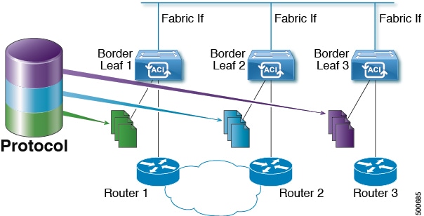
When fast convergence mode is enabled, every border leaf in the fabric will send PIM joins towards the root (RP for (*,G) and source (S,G)) in the external network. This allows all PIM enabled BLs in the fabric to receive the multicast traffic from external sources but only one BL will forward traffic onto the fabric. The BL that forwards the multicast traffic onto the fabric is the designated forwarder. The stripe winner BL decides on the DF. The advantage of the fast-convergence mode is that when there is a changed of the stripe winner due to a BL failure there is no latency incurred in the external network by having the new BL send joins to create multicast state.

Note: Fast convergence mode can be disabled in deployments where the cost of additional bandwidth outweighs the convergence time saving.

Strict RFC Compliant

ip pim strict-rfc-compliant

When configured, the switch will not process joins from unknown neighbors and will not send PIM joins to unknown neighbors

MTU Port

ippimmtu

Enables bigger frame sizes for the PIM control plane traffic and improves the convergence. Range is from 1500 to 9216 bytes

Resource Policy Maximum Limit

ip pim state-limit

Sets the maximum (*,G)/(S,G) entries allowed per VRF. Range is from 1 to 4294967295

Resource Policy Reserved Route Map*

ip pim state-limit <limit> reserved <route-map>

Configures a route-map policy matching multicast groups or groups and sources to be applied to the Resource Policy Maximum Limit reserved entries.

Resource Policy Reserved Multicast Entries

ip pim state-limit <limit> reserved <route-map> <limit>

Maximum reserved (*, G) and (S, G) entries allowed in this VRF. Must be less than or equal to the maximum states allowed. Used with the Resource Policy Reserved Route Map policy

Guidelines and Restrictions for Configuring Layer 3 Multicast

See the following guidelines and restrictions:

  • Custom QoS policy is not supported for Layer 3 multicast traffic sourced from outside the ACI fabric (received from L3Out).

  • Enabling PIMv4 (Protocol-Independent Multicast, version 4) and Advertise Host routes on a BD is not supported.

  • If the border leaf switches in your ACI fabric are running multicast and you disable multicast on the L3Out while you still have unicast reachability, you will experience traffic loss if the external peer is a Cisco Nexus 9000 switch. This impacts cases where traffic is destined towards the fabric (where the sources are outside the fabric but the receivers are inside the fabric) or transiting through the fabric (where the source and receivers are outside the fabric, but the fabric is transit).

  • If the (s, g) entry is installed on a border leaf switch, you might see drops in unicast traffic that comes from the fabric to this source outside the fabric when the following conditions are met:

    • Preferred group is used on the L3Out EPG

    • Unicast routing table for the source is using the default route 0.0.0.0/0

    This behavior is expected.

  • The Layer 3 multicast configuration is done at the VRF level so protocols function within the VRF and multicast is enabled in a VRF, and each multicast VRF can be turned on or off independently.

  • Once a VRF is enabled for multicast, the individual bridge domains (BDs) and L3 Outs under the enabled VRF can be enabled for multicast configuration. By default, multicast is disabled in all BDs and Layer 3 Outs.

  • Layer 3 multicast is not currently supported on VRFs that are configured with a shared L3 Out.

  • Any Source Multicast (ASM) and Source-Specific Multicast (SSM) are supported.

  • You can configure a maximum of four ranges for SSM multicast in the route map per VRF.

  • Bidirectional PIM, Rendezvous Point (RP) within the ACI fabric, and PIM IPv6 are currently not supported

  • IGMP snooping cannot be disabled on pervasive bridge domains with multicast routing enabled.

  • Multicast routers are not supported in pervasive bridge domains.

  • The Layer 3 multicast feature is supported on the following leaf switches:

    • EX models:

      • N9K-93108TC-EX

      • N9K-93180LC-EX

      • N9K-93180YC-EX

    • FX models:

      • N9K-93108TC-FX

      • N9K-93180YC-FX

      • N9K-C9348GC-FXP

    • FX2 models:

      • N9K-93240YC-FX2

      • N9K-C9336C-FX2

  • PIM is supported on Layer 3 Out routed interfaces and routed subinterfaces including Layer 3 port-channel interfaces. PIM is not supported on Layer 3 Out SVI interfaces.

  • Enabling PIM on an L3Out causes an implicit external network to be configured. This action results in the L3Out being deployed and protocols potentially coming up even if you have not defined an external network.

  • If the multicast source is connected to Leaf-A as an orphan port and you have an L3Out on Leaf-B, and Leaf-A and Leaf-B are in a vPC pair, the EPG encapsulation VLAN tied to the multicast source will need to be deployed on Leaf-B.

  • For Layer 3 multicast support, when the ingress leaf switch receives a packet from a source that is attached on a bridge domain, and the bridge domain is enabled for multicast routing, the ingress leaf switch sends only a routed VRF copy to the fabric (routed implies that the TTL is decremented by 1, and the source-mac is rewritten with a pervasive subnet MAC). The egress leaf switch also routes the packet into receivers in all the relevant bridge domains. Therefore, if a receiver is on the same bridge domain as the source, but on a different leaf switch than the source, that receiver continues to get a routed copy, although it is in the same bridge domain. This also applies if the source and receiver are on the same bridge domain and on the same leaf switch, if PIM is enabled on this bridge domain.

    For more information, see details about Layer 3 multicast support for multipod that leverages existing Layer 2 design, at the following link Adding Pods.

  • Starting with release 3.1(1), Layer 3 multicast is supported with FEX. Multicast sources or receivers that are connected to FEX ports are supported. For further details about how to add FEX in your testbed, see Configure a Fabric Extender with Application Centric Infrastructure at this URL: https://www.cisco.com/c/en/us/support/docs/cloud-systems-management/application-policy-infrastructure-controller-apic/200529-Configure-a-Fabric-Extender-with-Applica.html. For releases preceeding release 3.1(1), Layer 3 multicast is not supported with FEX. Multicast sources or receivers that are connected to FEX ports are not supported.

  • You cannot use a filter with inter-VRF multicast communication.


Note


Cisco ACI does not support IP fragmentation. Therefore, when you configure Layer 3 Outside (L3Out) connections to external routers, or Multi-Pod connections through an Inter-Pod Network (IPN), it is recommended that the interface MTU is set appropriately on both ends of a link. On some platforms, such as Cisco ACI, Cisco NX-OS, and Cisco IOS, the configurable MTU value does not take into account the Ethernet headers (matching IP MTU, and excluding the 14-18 Ethernet header size), while other platforms, such as IOS-XR, include the Ethernet header in the configured MTU value. A configured value of 9000 results in a max IP packet size of 9000 bytes in Cisco ACI, Cisco NX-OS, and Cisco IOS, but results in a max IP packet size of 8986 bytes for an IOS-XR untagged interface.

For the appropriate MTU values for each platform, see the relevant configuration guides.

We highly recommend that you test the MTU using CLI-based commands. For example, on the Cisco NX-OS CLI, use a command such as ping 1.1.1.1 df-bit packet-size 9000 source-interface ethernet 1/1.


Configuring Layer 3 Multicast Using the GUI

Before you begin

  • The desired VRF, bridge domains, Layer 3 Out interfaces with IP addresses must be configured to enable PIM and IGMP.

  • Basic unicast network must be configured.

Procedure


Step 1

Navigate to Tenants > Tenant_name > Networking > VRFs > VRF_name > Multicast.

In the Work pane, a message is displayed as follows: PIM is not enabled on this VRF. Would you like to enable PIM?.

Step 2

Click YES, ENABLE MULTICAST.

Step 3

In the Work pane, click the Interfaces tab.

Step 4

In the Bridge Domain area, perform the following actions:

  1. Click the BD drop-down list to choose the desired BD.

  2. Click the IGMP Policy drop-down list to choose the desired IGMP Policy.

    You can choose Create IGMP Policy to create a new IGMP Policy, or you can use the default policy.

Step 5

In the Interfaces area, perform the following actions:

  1. Expand Interfaces and in the Select and L3 Out dialog box, from the L3 Out drop-down list, choose the desired L3 Out.

  2. Click Select.

Step 6

Click the Rendezvous Points tab.

Step 7

Choose the desired Rendezvous Point (RP) from the available options. You can specify static RP, auto RP, or bootstrap router, or choose the desired combination of the RPs to configure.

Step 8

(Optional) Expand Static RP, and from the RouteMap drop-down list, click Create RouteMap Policy, and perform the following actions:

This is a specific route map configured for multicast. If the route map you desire is already present, choose that instead of creating a new route map.

  1. In the Name field, enter a name for the routemap policy.

  2. Enter the values in the fields for Order, Source IP , Group IP, RP IP for that entry.

  3. In the Action field, choose the desired action to permit or deny. Click OK.

  4. Click Submit to display the entry under RouteMaps.

Step 9

In the Work pane, click the Pattern Policy tab.

Step 10

Click Pattern Policy and choose the desired multicast option.

Choose the Multicast Route Map for each of the policies.

Step 11

Click the PIM Settings tab and set the desired PIM Setting and Resource Policy values.

Step 12

Click the IGMP Setting tab.

  1. In the Group Prefix and the Source Address fields, enter the appropriate values for both.

  2. Click Update to complete the IGMP Settings for that particular bridge domain.

Step 13

To verify the configuration perform the following actions:

  1. In the Work pane, click Interfaces to display the associated Bridge Domains.

  2. Click Interfaces to display the associated L3 Out interfaces.

  3. In the Navigation pane, navigate to the BD.

  4. In the Work pane, the configured IGMP policy and PIM functionality are displayed as configured earlier.

  5. In the Navigation pane, the L3 Out interface is displayed.

  6. In the Work pane, the PIM functionality is displayed as configured earlier.

  7. In the Work pane, navigate to Fabric > Inventory > Protocols > IGMP to view the operational status of the configured IGMP interfaces.

  8. In the Work pane, navigate to Fabric > Inventory > Pod name > Leaf_Node > Protocols > IGMP > IGMP Domains to view the domain information for multicast enabled/disabled nodes.


Configuring Layer 3 Multicast Using the NX-OS Style CLI

Procedure


Step 1

Enter the configure mode.

Example:

apic1# configure

Step 2

Enter the configure mode for a tenant, the configure mode for the VRF, and configure PIM options.

Example:

apic1(config)# tenant tenant1
apic1(config-tenant)# vrf context tenant1_vrf
apic1(config-tenant-vrf)# ip pim
apic1(config-tenant-vrf)# ip pim fast-convergence
apic1(config-tenant-vrf)# ip pim bsr forward

Step 3

Configure IGMP and the desired IGMP options for the VRF.

Example:

apic1(config-tenant-vrf)# ip igmp
apic1(config-tenant-vrf)# exit 
apic1(config-tenant)# interface bridge-domain tenant1_bd
apic1(config-tenant-interface)# ip multicast
apic1(config-tenant-interface)# ip igmp allow-v3-asm
apic1(config-tenant-interface)# ip igmp fast-leave
apic1(config-tenant-interface)# ip igmp inherit interface-policy igmp_intpol1
apic1(config-tenant-interface)# exit

Step 4

Enter the L3 Out mode for the tenant, enable PIM, and enter the leaf interface mode. Then configure PIM for this interface.

Example:

apic1(config-tenant)# l3out tenant1_l3out
apic1(config-tenant-l3out)# ip pim
apic1(config-tenant-l3out)# exit
apic1(config-tenant)# exit
apic1(config)# 
apic1(config)# leaf 101
apic1(config-leaf)# interface ethernet 1/125 
apic1(config-leaf-if) ip pim inherit interface-policy pim_intpol1

Step 5

Configure IGMP for the interface using the IGMP commands.

Example:


apic1(config-leaf-if)# ip igmp fast-leave
apic1(config-leaf-if)# ip igmp inherit interface-policy igmp_intpol1
This completes the APIC Layer 3 multicast configuration.

Configuring Layer 3 Multicast Using REST API

Procedure


Step 1

Configure tenant, VRF, and enable multicast on VRF.

Example:

<fvTenant dn="uni/tn-PIM_Tenant" name="PIM_Tenant">
   <fvCtx knwMcastAct="permit" name="ctx1">
       <pimCtxP mtu="1500">
       </pimCtxP>
   </fvCtx>
  </fvTenant>

Step 2

Configure L3 Out and enable multicast (PIM, IGMP) on L3 Out.

Example:

<l3extOut enforceRtctrl="export" name="l3out-pim_l3out1">
       <l3extRsEctx tnFvCtxName="ctx1"/>
       <l3extLNodeP configIssues="" name="bLeaf-CTX1-101">
         <l3extRsNodeL3OutAtt rtrId="200.0.0.1" rtrIdLoopBack="yes" tDn="topology/pod-1/node-101"/>
         <l3extLIfP name="if-PIM_Tenant-CTX1" tag="yellow-green">
           <igmpIfP/>
           <pimIfP>
             <pimRsIfPol tDn="uni/tn-PIM_Tenant/pimifpol-pim_pol1"/>
           </pimIfP>
           <l3extRsPathL3OutAtt addr="131.1.1.1/24" ifInstT="l3-port" mode="regular" mtu="1500" tDn="topology/pod-1/paths-101/pathep-[eth1/46]"/>
         </l3extLIfP>
       </l3extLNodeP>
       <l3extRsL3DomAtt tDn="uni/l3dom-l3outDom"/>
       <l3extInstP name="l3out-PIM_Tenant-CTX1-1topo" >
       </l3extInstP>
       <pimExtP enabledAf="ipv4-mcast" name="pim"/>
     </l3extOut>

Step 3

Configure BD under tenant and enable multicast and IGMP on BD.

Example:

<fvTenant dn="uni/tn-PIM_Tenant" name="PIM_Tenant">
   <fvBD arpFlood="yes" mcastAllow="yes" multiDstPktAct="bd-flood" name="bd2" type="regular" unicastRoute="yes" unkMacUcastAct="flood" unkMcastAct="flood">
       <igmpIfP/>
       <fvRsBDToOut tnL3extOutName="l3out-pim_l3out1"/>
       <fvRsCtx tnFvCtxName="ctx1"/>
       <fvRsIgmpsn/>
       <fvSubnet ctrl="" ip="41.1.1.254/24" preferred="no" scope="private" virtual="no"/>
     </fvBD>
 </fvTenant>

Step 4

Configure IGMP policy and assign it to BD.

Example:

<fvTenant dn="uni/tn-PIM_Tenant" name="PIM_Tenant">
     <igmpIfPol grpTimeout="260" lastMbrCnt="2" lastMbrRespTime="1" name="igmp_pol" querierTimeout="255" queryIntvl="125" robustFac="2" rspIntvl="10" startQueryCnt="2" startQueryIntvl="125" ver="v2">
     </igmpIfPol>
      <fvBD arpFlood="yes" mcastAllow="yes" name="bd2">
      <igmpIfP>
         <igmpRsIfPol tDn="uni/tn-PIM_Tenant/igmpIfPol-igmp_pol"/>
       </igmpIfP>
      </fvBD>
 </fvTenant>

Step 5

Configure route map, PIM, and RP policy on VRF.

Example:

<fvTenant dn="uni/tn-PIM_Tenant" name="PIM_Tenant">
     <pimRouteMapPol name="rootMap">
       <pimRouteMapEntry action="permit" grp="224.0.0.0/4" order="10" rp="0.0.0.0" src="0.0.0.0/0"/>
     </pimRouteMapPol>
     <fvCtx knwMcastAct="permit" name="ctx1">
       <pimCtxP ctrl="" mtu="1500">
         <pimStaticRPPol>
           <pimStaticRPEntryPol rpIp="131.1.1.2">
             <pimRPGrpRangePol>
               <rtdmcRsFilterToRtMapPol tDn="uni/tn-PIM_Tenant/rtmap-rootMap"/>
             </pimRPGrpRangePol>
           </pimStaticRPEntryPol>
         </pimStaticRPPol>
       </pimCtxP>
   </fvCtx>
</fvTenant>

Step 6

Configure PIM interface policy and apply it on L3 Out.

Example:

<fvTenant dn="uni/tn-PIM_Tenant" name="PIM_Tenant">
  <pimIfPol authKey="" authT="none" ctrl="" drDelay="60" drPrio="1" helloItvl="30000" itvl="60" name="pim_pol1"/>
  <l3extOut enforceRtctrl="export" name="l3out-pim_l3out1" targetDscp="unspecified">
       <l3extRsEctx tnFvCtxName="ctx1"/>
       <l3extLNodeP  name="bLeaf-CTX1-101">
         <l3extRsNodeL3OutAtt rtrId="200.0.0.1" rtrIdLoopBack="yes" tDn="topology/pod-1/node-101"/>
         <l3extLIfP name="if-SIRI_VPC_src_recv-CTX1" tag="yellow-green">
           <pimIfP>
             <pimRsIfPol tDn="uni/tn-tn-PIM_Tenant/pimifpol-pim_pol1"/>
           </pimIfP>
         </l3extLIfP>
       </l3extLNodeP>
     </l3extOut>
 </fvTenant>

1 All multicast group membership information is stored in the COOP database on the spines. When a border leaf boots up it pulls this information from the spine