Switch Virtual Interface

This chapter contains the following sections:

SVI External Encapsulation Scope

About SVI External Encapsulation Scope

In the context of a Layer 3 Out configuration, a switch virtual interfaces (SVI), is configured to provide connectivity between the ACI leaf switch and a router.

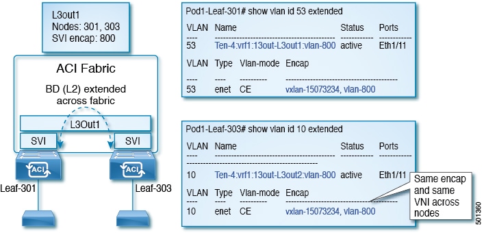
By default, when a single Layer 3 Out is configured with SVI interfaces, the VLAN encapsulation spans multiple nodes within the fabric. This happens because the ACI fabric configures the same bridge domain (VXLAN VNI) across all the nodes in the fabric where the Layer 3 Out SVI is deployed as long as all SVI interfaces use the same external encapsulation (SVI) as shown in the figure.

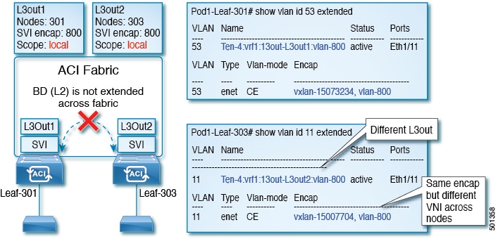
However, when different Layer 3 Outs are deployed, the ACI fabric uses different bridge domains even if they use the same external encapsulation (SVI) as shown in the figure:

Figure 1. Local Scope Encapsulation and One Layer 3 Out
Figure 2. Local Scope Encapsulation and Two Layer 3 Outs

Starting with Cisco APIC release 2.3, it is now possible to choose the behavior when deploying two (or more) Layer 3 Outs using the same external encapsulation (SVI).

The encapsulation scope can now be configured as Local or VRF:

  • Local scope (default): The example behavior is displayed in the figure titled Local Scope Encapsulation and Two Layer 3 Outs.

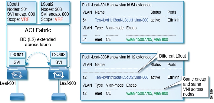
  • VRF scope: The ACI fabric configures the same bridge domain (VXLAN VNI) across all the nodes and Layer 3 Out where the same external encapsulation (SVI) is deployed. See the example in the figure titled VRF Scope Encapsulation and Two Layer 3 Outs.

Figure 3. VRF Scope Encapsulation and Two Layer 3 Outs

Encapsulation Scope Syntax

The options for configuring the scope of the encapsulation used for the Layer 3 Out profile are as follows:

  • Ctx—The same external SVI in all Layer 3 Outs in the same VRF for a given VLAN encapsulation. This is a global value.

  • Local —A unique external SVI per Layer 3 Out. This is the default value.

The mapping among the CLI, API, and GUI syntax is as follows:

Table 1. Encapsulation Scope Syntax

CLI

API

GUI

l3out

local

Local

vrf

ctx

VRF


Note


The CLI commands to configure encapsulation scope are only supported when the VRF is configured through a named Layer 3 Out configuration.


Guidelines for SVI External Encapsulation Scope

To use SVI external encapsulation scope, follow these guidelines:

  • If deploying the Layer 3 Outs on the same node, the OSPF areas in both the Layer 3 Outs must be different.

  • If deploying the Layer 3 Outs on the same node, the BGP peer configured on both the Layer 3 Outs must be different.

Configuring SVI External Encapsulation Scope Using the GUI

Before you begin

  • The tenant and VRF configured.

  • A Layer 3 Out is configured and a logical node profile under the Layer 3 Out is configured.

Procedure


Step 1

On the menu bar, click > Tenants > Tenant_name. In the Navigation pane, click Networking > External Routed Networks > External Routed Network_name > Logical Node Profiles > Logical Interface Profile.

Step 2

In the Navigation pane, right-click Logical Interface Profile, and click Create Interface Profile.

Step 3

In the Create Interface Profile dialog box, perform the following actions:

  1. In the Step 1 Identity screen, in the Name field, enter a name for the interface profile.

  2. In the remaining fields, choose the desired options, and click Next.

  3. In the Step 2 Protocol Profiles screen, choose the desired protocol profile details, and click Next.

  4. In the Step 3 Interfaces screen, click the SVI tab, and click the + icon to open the Select SVI dialog box.

  5. In the Specify Interface area, choose the desired values for the various fields.

  6. In the Encap Scope field, choose the desired encapsulation scope value. Click OK.

    The default value is Local.


The SVI External encapsulation scope is configured in the specified interface.

Configuring SVI Interface Encapsulation Scope Using NX-OS Style CLI

The following example displaying steps for an SVI interface encapsulation scope setting is through a named Layer 3 Out configuration.

Procedure

  Command or Action Purpose

Step 1

Enter the configure mode.

Example:

apic1# configure

Enters the configuration mode.

Step 2

Enter the switch mode.

Example:

apic1(config)# leaf 104

Enters the switch mode.

Step 3

Create the VLAN interface.

Example:

apic1(config-leaf)# interface vlan 2001

Creates the VLAN interface. The VLAN range is 1-4094.

Step 4

Specify the encapsulation scope.

Example:

apic1(config-leaf-if)# encap scope vrf context

Specifies the encapsulation scope.

Step 5

Exit the interface mode.

Example:

apic1(config-leaf-if)# exit

Exits the interface mode.

Configuring SVI Interface Encapsulation Scope Using the REST API

Before you begin

The interface selector is configured.

Procedure


Configure the SVI interface encapsulation scope.

Example:


<?xml version="1.0" encoding="UTF-8"?>
<!-- /api/node/mo/.xml -->
<polUni>
	<fvTenant name="coke">
		<l3extOut descr="" dn="uni/tn-coke/out-l3out1" enforceRtctrl="export" name="l3out1" nameAlias="" ownerKey="" ownerTag="" targetDscp="unspecified">
			<l3extRsL3DomAtt tDn="uni/l3dom-Dom1"/>
			<l3extRsEctx tnFvCtxName="vrf0"/>
			<l3extLNodeP configIssues="" descr="" name="__ui_node_101" nameAlias="" ownerKey="" ownerTag="" tag="yellow-green" targetDscp="unspecified">
				<l3extRsNodeL3OutAtt rtrId="1.1.1.1" rtrIdLoopBack="no" tDn="topology/pod-1/node-101"/>
				<l3extLIfP descr="" name="int1_11" nameAlias="" ownerKey="" ownerTag="" tag="yellow-green">
					<l3extRsPathL3OutAtt addr="1.2.3.4/24" descr="" encap="vlan-2001" encapScope="ctx" ifInstT="ext-svi" llAddr="0.0.0.0" mac="00:22:BD:F8:19:FF" mode="regular" mtu="inherit" tDn="topology/pod-1/paths-101/pathep-[eth1/5]" targetDscp="unspecified"/>
					<l3extRsNdIfPol tnNdIfPolName=""/>
					<l3extRsIngressQosDppPol tnQosDppPolName=""/>
					<l3extRsEgressQosDppPol tnQosDppPolName=""/>
				</l3extLIfP>
			</l3extLNodeP>
			<l3extInstP descr="" matchT="AtleastOne" name="epg1" nameAlias="" prefGrMemb="exclude" prio="unspecified" targetDscp="unspecified">
				<l3extSubnet aggregate="" descr="" ip="101.10.10.1/24" name="" nameAlias="" scope="import-security"/>
				<fvRsCustQosPol tnQosCustomPolName=""/>
			</l3extInstP>
		</l3extOut>
	</fvTenant>
</polUni>

SVI Auto State

About SVI Auto State


Note


This feature is available in the APIC Release 2.2(3x) release and going forward with APIC Release 3.1(1). It is not supported in APIC Release 3.0(x).


The Switch Virtual Interface (SVI) represents a logical interface between the bridging function and the routing function of a VLAN in the device. SVI can have members that are physical ports, direct port channels, or virtual port channels. The SVI logical interface is associated with VLANs, and the VLANs have port membership.

The SVI state does not depend on the members. The default auto state behavior for SVI in Cisco APIC is that it remains in the up state when the auto state value is disabled. This means that the SVI remains active even if no interfaces are operational in the corresponding VLAN/s.

If the SVI auto state value is changed to enabled, then it depends on the port members in the associated VLANs. When a VLAN interface has multiple ports in the VLAN, the SVI goes to the down state when all the ports in the VLAN go down.

Table 2. SVI Auto State

SVI Auto State

Description of SVI State

Disabled

SVI remains in the up state even if no interfaces are operational in the corresponding VLAN/s.

Disabled is the default SVI auto state value.

Enabled

SVI depends on the port members in the associated VLANs. When a VLAN interface contains multiple ports, the SVI goes into the down state when all the ports in the VLAN go down.

Guidelines and Limitations for SVI Auto State Behavior

Read the following guidelines:

  • When you enable or disable the auto state behavior for SVI, you configure the auto state behavior per SVI. There is no global command.

Configuring SVI Auto State Using the GUI

Before you begin

  • The tenant and VRF configured.

  • A Layer 3 Out is configured and a logical node profile and a logical interface profile under the Layer 3 Out is configured.

Procedure


Step 1

On the menu bar, click > Tenants > Tenant_name. In the Navigation pane, click Networking > External Routed Networks > External Routed Network_name > Logical Node Profiles > Logical Interface Profile.

Step 2

In the Navigation pane, expand Logical Interface Profile, and click the appropriate logical interface profile.

Step 3

In the Work pane, click the + sign to display the SVI dialog box.

Step 4

To add an additional SVI, in the SVI dialog box, perform the following actions:

  1. In the Path Type field, choose the appropriate path type.

  2. In the Path field, from the drop-down list, choose the appropriate physical interface.

  3. In the Encap field, choose the appropriate values.

  4. In the Auto State field, choose the SVI in the Work pane, to view/change the Auto State value.

    The default value is Disabled.

    Note


    To verify or change the Auto State value for an existing SVI, choose the appropriate SVI and verify or change the value.


Configuring SVI Auto State Using NX-OS Style CLI

Before you begin

  • The tenant and VRF configured.

  • A Layer 3 Out is configured and a logical node profile and a logical interface profile under the Layer 3 Out is configured.

Procedure

  Command or Action Purpose

Step 1

Enter the configure mode.

Example:

apic1# configure

Enters the configuration mode.

Step 2

Enter the switch mode.

Example:

apic1(config)# leaf 104

Enters the switch mode.

Step 3

Create the VLAN interface.

Example:

apic1(config-leaf)# interface vlan 2001

Creates the VLAN interface. The VLAN range is 1-4094.

Step 4

Enable SVI auto state.

Example:

apic1(config-leaf-if)# autostate

Enables SVI auto state.

By default, the SVI auto state value is not enabled.

Step 5

Exit the interface mode.

Example:

apic1(config-leaf-if)# exit

Exits the interface mode.

Configuring SVI Auto State Using the REST API

Before you begin

  • The tenant and VRF configured.

  • A Layer 3 Out is configured and a logical node profile and a logical interface profile under the Layer 3 Out is configured.

Procedure


Enable the SVI auto state value.

Example:


<fvTenant name="t1" >
   <l3extOut name="out1">
      <l3extLNodeP name="__ui_node_101" >
         <l3extLIfP descr="" name="__ui_eth1_10_vlan_99_af_ipv4" >
            <l3extRsPathL3OutAtt addr="19.1.1.1/24" autostate="enabled" descr="" encap="vlan-100" encapScope="local" ifInstT="ext-svi" llAddr="::" mac="00:22:BD:F8:19:FF" mode="regular" mtu="inherit" tDn="topology/pod-1/paths-101/pathep-[eth1/10]" targetDscp="unspecified" />
         </l3extLIfP>
      </l3extLNodeP>
   </l3extOut>
</fvTenant>

To disable the autostate, you must change the value to disabled in the above example. For example, autostate="disabled".