Remote Leaf Switches

This chapter contains the following sections:

About Remote Leaf Switches in the ACI Fabric

With an ACI fabric deployed, you can extend ACI services and APIC management to remote datacenters with Cisco ACI leaf switches that have no local spine switch or APIC attached.

Figure 1. Remote Leaf Topology

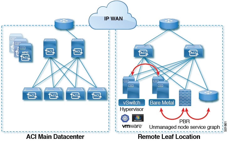
The remote leaf switches are added to an existing pod in the fabric. All policies deployed in the main datacenter are deployed in the remote switches, which behave like local leaf switches belonging to the pod. In this topology, all unicast traffic is through VXLAN over Layer 3. Layer 2 Broadcast, Unknown Unicast, and Multicast (BUM) messages are sent using Head End Replication (HER) tunnels without the use of Multicast. All local traffic on the remote site is switched directly between endpoints, whether physical or virtual. Any traffic that requires use of the spine switch proxy is forwarded to the main datacenter.

The APIC system discovers the remote leaf switches when they come up. From that time, they can be managed through APIC, as part of the fabric.


Note


  • All inter-VRF traffic goes to the spine switch before being forwarded.

  • Before decommissioning a remote leaf, you must first delete the vPC.


You can configure Remote Leaf in the APIC GUI, either with and without a wizard, or use the REST API or the NX-OS style CLI.

Remote Leaf Switch Hardware Requirements

The following switches are supported for the Remote Leaf Switch feature.

Fabric Spine Switches

For the spine switch at the ACI Main Datacenter that is connected to the WAN router, the following spine switches are supported:

  • Fixed spine switches Cisco Nexus 9000 series:

    • N9K-C9316D-GX

    • N9K-C9332C

    • N9K-C9364C

    • N9K-C9364C-GX

  • For modular spine switches, only Cisco Nexus 9000 series switches with names that end in EX, and later (for example, N9K-X9732C- EX ) are supported.

  • Older generation spine switches, such as the fixed spine switch N9K-C9336PQ or modular spine switches with the N9K-X9736PQ linecard are supported in the Main Datacenter, but only next generation spine switches are supported to connect to the WAN.

Remote Leaf Switches

  • For the remote leaf switches, only Cisco Nexus 9000 series switches with names that end in EX, and later (for example, N9K-C93180LC-EX) are supported.

  • The remote leaf switches must be running a switch image of 13.1.x or later (aci-n9000-dk9.13.1.x.x.bin) before they can be discovered. This may require manual upgrades on the leaf switches.

Remote Leaf Switch Restrictions and Limitations

The following guidelines and restrictions apply to remote leaf switches:

  • A remote leaf vPC pair has a split brain condition when the DP-TEP address of one of the switches is not reachable from the peer. In this case, both remote leaf switches are up and active in the fabric and the COOP session is also up on both of the peers. One of the remote leaf switches does not have a route to the DP-TEP address of its peer, and due to this, the vPC has a split brain condition. Both of the node roles is changed to "primary" and all the front panel links are up in both of the peers while the zero message queue (ZMQ) session is down.

  • The remote leaf solution requires the /32 tunnel end point (TEP) IP addresses of the remote leaf switches and main data center leaf/spine switches to be advertised across the main data center and remote leaf switches without summarization.

  • If you move a remote leaf switch to a different site within the same pod and the new site has the same node ID as the original site, you must delete and recreate the virtual port channel (vPC).

  • With the Cisco N9K-C9348GC-FXP switch, you can perform the initial remote leaf switch discovery only on ports 1/53 or 1/54. Afterward, you can use the other ports for fabric uplinks to the ISN/IPN for the remote leaf switch.

The following sections provide information on what is supported and not supported with remote leaf switches:

Supported Features

Beginning with Cisco APIC release 3.2(x), the following features are supported:

  • FEX devices connected to remote leaf switches

  • Cisco AVS with VLAN and Cisco AVS with VXLAN

  • Cisco ACI Virtual Edge with VLAN and ACI Virtual Edge with VXLAN

  • The Cisco Nexus 9336C-FX2 switch is now supported for remote leaf switches

Unsupported Features

Stretching of an L3Out SVI between local leaf switches (ACI main data center switches) and remote leaf switches is not supported.

The following deployments and configurations are not supported with the remote leaf switch feature:

  • APIC controllers directly connected to remote leaf switches

  • Orphan port-channel or physical ports on remote leaf switches, with a vPC domain (this restriction applies for releases 3.1 and earlier)

  • With and without service node integration, local traffic forwarding within a remote location is only supported if the consumer, provider, and services nodes are all connected to Remote Leaf switches are in vPC mode

Full fabric and tenant policies are supported on remote leaf switches in this release with the exception of the following features, which are unsupported:

  • GOLF

  • vPod

  • Floating L3Out

  • Fast-convergence mode

  • Stretching of L3Out SVI between local leaf switches (ACI main data center switches) and remote leaf switches or stretching across two different vPC pairs of remote leaf switches

  • Copy service is not supported when deployed on local leaf switches and when the source or destination is on the remote leaf switch. In this situation, the routable TEP IP address is not allocated for the local leaf switch. For more information, see the section "Copy Services Limitations" in the "Configuring Copy Services" chapter in the Cisco APIC Layer 4 to Layer 7 Services Deployment Guide, available in the APIC documentation page.

  • ACI Multi-Site

  • Layer 2 Outside Connections (except Static EPGs)

  • 802.1Q Tunnels

  • Copy services with vzAny contract

  • FCoE connections on remote leaf switches

  • Flood in encapsulation for bridge domains or EPGs

  • Fast Link Failover policies

  • Managed Service Graph-attached devices at remote locations

  • Netflow

  • PBR Tracking on remote leaf switches (with system-level global GIPo enabled)

  • Q-in-Q Encapsulation Mapping for EPGs

  • Traffic Storm Control

  • Cloud Sec and MacSec Encryption

  • First Hop Security

  • Layer 3 Multicast routing on remote leaf switches

  • Openstack and Kubernetes VMM domains

  • Maintenance mode

  • Troubleshooting wizard

  • Transit L3Out across remote locations, which is when the main Cisco ACI data center pod is a transit between two remote locations (the L3Out in RL location-1 and L3Out in RL location-2 are advertising prefixes for each other)

  • Traffic forwarding directly across two remote leaf vPC pairs in the same remote data center or across data centers, when those remote leaf pairs are associated to the same pod or to pods that are part of the same multipod fabric

The following scenarios are not supported when integrating remote leaf switches in a Multi-Site architecture in conjunction with the intersite L3Out functionality:

  • Transit routing between L3Outs deployed on remote leaf switch pairs associated to separate sites

  • Endpoints connected to a remote leaf switch pair associated to a site communicating with the L3Out deployed on the remote leaf switch pair associated to a remote site

  • Endpoints connected to the local site communicating with the L3Out deployed on the remote leaf switch pair associated to a remote site

  • Endpoints connected to a remote leaf switch pair associated to a site communicating with the L3Out deployed on a remote site


Note


The limitations above do not apply if the different data center sites are deployed as pods as part of the same Multi-Pod fabric.


WAN Router and Remote Leaf Switch Configuration Guidelines

Before a remote leaf is discovered and incorporated in APIC management, you must configure the WAN router and the remote leaf switches.

Configure the WAN routers that connect to the fabric spine switch external interfaces and the remote leaf switch ports, with the following requirements:

WAN Routers

  • Enable OSPF on the interfaces, with the same details, such as area ID, type, and cost.

  • Configure DHCP Relay on the interface leading to each APIC's IP address in the main fabric.

  • The interfaces on the WAN routers which connect to the VLAN-5 interfaces on the spine switches must be on different VRFs than the interfaces connecting to a regular multipod network.

Remote Leaf Switches

  • Connect the remote leaf switches to an upstream router by a direct connection from one of the fabric ports. The following connections to the upstream router are supported:

    • 40 Gbps & higher connections

    • With a QSFP-to-SFP Adapter, supported 1G/10G SFPs

    Bandwidth in the WAN must be a minimum of 100 Mbps and maximum supported latency is 300 msecs.

  • It is recommended, but not required to connect the pair of remote leaf switches with a vPC. The switches on both ends of the vPC must be remote leaf switches at the same remote datacenter.

  • Configure the northbound interfaces as Layer 3 sub-interfaces on VLAN-4, with unique IP addresses.

    If you connect more than one interface from the remote leaf switch to the router, configure each interface with a unique IP address.

  • Enable OSPF on the interfaces, but do not set the OSPF area type as stub area.

  • The IP addresses in the remote leaf switch TEP Pool subnet must not overlap with the pod TEP subnet pool. The subnet used must be /24 or lower.

  • Multipod is supported, but not required, with the Remote Leaf feature.

  • When connecting a pod in a single-pod fabric with remote leaf switches, configure an L3Out from a spine switch to the WAN router and an L3Out from a remote leaf switch to the WAN router, both using VLAN-4 on the switch interfaces.

  • When connecting a pod in a multipod fabric with remote leaf switches, configure an L3Out from a spine switch to the WAN router and an L3Out from a remote leaf switch to the WAN router, both using VLAN-4 on the switch interfaces. Also configure a multipod-internal L3Out using VLAN-5 to support traffic that crosses pods destined to a remote leaf switch. The regular multipod and multipod-internal connections can be configured on the same physical interfaces, as long as they use VLAN-4 and VLAN-5.

  • When configuring the Multipod-internal L3Out, use the same router ID as for the regular multipod L3Out, but deselect the Use Router ID as Loopback Address option for the router-id and configure a different loopback IP address. This enables ECMP to function.

Configure Remote Leaf Switches Using the REST API

To enable Cisco APIC to discover and connect the IPN router and remote leaf switches, perform the steps in this topic.

This example assumes that the remote leaf switches are connected to a pod in a multipod topology. It includes two L3Outs configured in the infra tenant, with VRF overlay-1:

  • One is configured on VLAN-4, that is required for both the remote leaf switches and the spine switch connected to the WAN router.

  • One is the multipod-internal L3Out configured on VLAN-5, that is required for the multipod and Remote Leaf features, when they are deployed together.

Procedure


Step 1

To define the TEP pool for two remote leaf switches to be connected to a pod, send a post with XML such as the following example:

Example:

<fabricSetupPol>
      <fabricSetupP tepPool="10.0.0.0/16" podId="1" >
           <fabricExtSetupP tepPool="30.0.128.0/20" extPoolId="1"/>
     </fabricSetupP>
     <fabricSetupP tepPool="10.1.0.0/16" podId="2" >
          <fabricExtSetupP tepPool="30.1.128.0/20" extPoolId="1"/>
     </fabricSetupP>
</fabricSetupPol>

Step 2

To define the node identity policy, send a post with XML, such as the following example:

Example:

<fabricNodeIdentPol>
     <fabricNodeIdentP serial="SAL17267Z7W" name="leaf1" nodeId="101" podId="1" 
extPoolId="1" nodeType="remote-leaf-wan"/>
     <fabricNodeIdentP serial="SAL17267Z7X" name="leaf2" nodeId="102" podId="1" 
extPoolId="1" nodeType="remote-leaf-wan"/>
     <fabricNodeIdentP serial="SAL17267Z7Y" name="leaf3" nodeId="201" podId="1" 
extPoolId="1" nodeType="remote-leaf-wan"/>
     <fabricNodeIdentP serial="SAL17267Z7Z" name="leaf4" nodeId="201" podId="1" 
extPoolId="1" nodeType="remote-leaf-wan"/>
</fabricNodeIdentPol>

Step 3

To configure the Fabric External Connection Profile, send a post with XML such as the following example:

Example:

<?xml version="1.0" encoding="UTF-8"?>
<imdata totalCount="1">
     <fvFabricExtConnP dn="uni/tn-infra/fabricExtConnP-1" id="1" name="Fabric_Ext_Conn_Pol1" rt="extended:as2-nn4:5:16" siteId="0">
           <l3extFabricExtRoutingP name="test">
                <l3extSubnet ip="150.1.0.0/16" scope="import-security"/>
           </l3extFabricExtRoutingP>
          <l3extFabricExtRoutingP name="ext_routing_prof_1">
               <l3extSubnet ip="204.1.0.0/16" scope="import-security"/>
               <l3extSubnet ip="209.2.0.0/16" scope="import-security"/>
               <l3extSubnet ip="202.1.0.0/16" scope="import-security"/>
               <l3extSubnet ip="207.1.0.0/16" scope="import-security"/>
               <l3extSubnet ip="200.0.0.0/8" scope="import-security"/>
               <l3extSubnet ip="201.2.0.0/16" scope="import-security"/>
               <l3extSubnet ip="210.2.0.0/16" scope="import-security"/>
               <l3extSubnet ip="209.1.0.0/16" scope="import-security"/>
               <l3extSubnet ip="203.2.0.0/16" scope="import-security"/>
               <l3extSubnet ip="208.1.0.0/16" scope="import-security"/>
               <l3extSubnet ip="207.2.0.0/16" scope="import-security"/>
               <l3extSubnet ip="100.0.0.0/8" scope="import-security"/>
               <l3extSubnet ip="201.1.0.0/16" scope="import-security"/>
               <l3extSubnet ip="210.1.0.0/16" scope="import-security"/>
               <l3extSubnet ip="203.1.0.0/16" scope="import-security"/>
               <l3extSubnet ip="208.2.0.0/16" scope="import-security"/>
          </l3extFabricExtRoutingP>
          <fvPodConnP id="1">
                <fvIp addr="100.11.1.1/32"/>
         </fvPodConnP>
         <fvPodConnP id="2">
               <fvIp addr="200.11.1.1/32"/>
         </fvPodConnP>
         <fvPeeringP type="automatic_with_full_mesh"/>
     </fvFabricExtConnP>
</imdata>

Step 4

To configure an L3Out on VLAN-4, that is required for both the remote leaf switches and the spine switch connected to the WAN router, enter XML such as the following example:

Example:

<?xml version="1.0" encoding="UTF-8"?>
<polUni>
<fvTenant name="infra">
  <l3extOut name="rleaf-wan-test">
    <ospfExtP areaId="0.0.0.5"/>
    <bgpExtP/>
    <l3extRsEctx tnFvCtxName="overlay-1"/>
    <l3extRsL3DomAtt tDn="uni/l3dom-l3extDom1"/>
    <l3extProvLbl descr="" name="prov_mp1" ownerKey="" ownerTag="" tag="yellow-green"/>
    <l3extLNodeP name="rleaf-101">
      <l3extRsNodeL3OutAtt rtrId="202.202.202.202" tDn="topology/pod-1/node-101">
      </l3extRsNodeL3OutAtt>
      <l3extLIfP name="portIf">
        <l3extRsPathL3OutAtt ifInstT="sub-interface" tDn="topology/pod-1/paths-101/pathep-[eth1/49]" addr="202.1.1.2/30" mac="AA:11:22:33:44:66" encap='vlan-4'/>
        <ospfIfP>
          <ospfRsIfPol tnOspfIfPolName='ospfIfPol'/>
        </ospfIfP>
      </l3extLIfP>
    </l3extLNodeP>
    <l3extLNodeP name="rlSpine-201">
      <l3extRsNodeL3OutAtt rtrId="201.201.201.201" rtrIdLoopBack="no" tDn="topology/pod-1/node-201">
        <!--
        <l3extLoopBackIfP addr="201::201/128" descr="" name=""/>
        <l3extLoopBackIfP addr="201.201.201.201/32" descr="" name=""/>
        -->
        <l3extLoopBackIfP addr="::" />
      </l3extRsNodeL3OutAtt>
      <l3extLIfP name="portIf">
        <l3extRsPathL3OutAtt ifInstT="sub-interface" tDn="topology/pod-1/paths-201/pathep-[eth8/36]" addr="201.1.1.1/30" mac="00:11:22:33:77:55" encap='vlan-4'/>
        <ospfIfP>
          <ospfRsIfPol tnOspfIfPolName='ospfIfPol'/>
        </ospfIfP>
      </l3extLIfP>
    </l3extLNodeP>
    <l3extInstP descr="" matchT="AtleastOne" name="instp1" prio="unspecified" targetDscp="unspecified">
      <fvRsCustQosPol tnQosCustomPolName=""/>
    </l3extInstP>
  </l3extOut>
  <ospfIfPol name="ospfIfPol" nwT="bcast"/>
</fvTenant>
</polUni>

Step 5

To configure the multipod L3Out on VLAN-5, that is required for both multipod and the remote leaf topology, send a post such as the following example:

Example:

<?xml version="1.0" encoding="UTF-8"?>                    
<polUni>                                                                                               
  <fvTenant  name="infra" >
    <l3extOut name="ipn-multipodInternal">
      <ospfExtP areaCtrl="inherit-ipsec,redistribute,summary" areaId="0.0.0.5" multipodInternal="yes" />
      <l3extRsEctx tnFvCtxName="overlay-1" />
      <l3extLNodeP name="bLeaf">
        <l3extRsNodeL3OutAtt rtrId="202.202.202.202" rtrIdLoopBack="no" tDn="topology/pod-2/node-202">
            <l3extLoopBackIfP addr="202.202.202.212"/>
       </l3extRsNodeL3OutAtt>
        <l3extRsNodeL3OutAtt rtrId="102.102.102.102" rtrIdLoopBack="no" tDn="topology/pod-1/node-102">
            <l3extLoopBackIfP addr="102.102.102.112"/>
       </l3extRsNodeL3OutAtt>
        <l3extLIfP name="portIf">
          <ospfIfP authKeyId="1" authType="none">
            <ospfRsIfPol tnOspfIfPolName="ospfIfPol" />
          </ospfIfP>
          <l3extRsPathL3OutAtt addr="10.0.254.233/30" encap="vlan-5" ifInstT="sub-interface" tDn="topology/pod-2/paths-202/pathep-[eth5/2]"/>
          <l3extRsPathL3OutAtt addr="10.0.255.229/30" encap="vlan-5" ifInstT="sub-interface" tDn="topology/pod-1/paths-102/pathep-[eth5/2]"/>
        </l3extLIfP>
      </l3extLNodeP>
      <l3extInstP matchT="AtleastOne" name="ipnInstP" />
    </l3extOut>
  </fvTenant>
</polUni>

Configure Remote Leaf Switches Using the NX-OS Style CLI

This example configures a spine switch and a remote leaf switch to enable the leaf switch to communicate with the main fabric pod.

Before you begin

  • The IPN router and remote leaf switches are active and configured; see WAN Router and Remote Leaf Switch Configuration Guidelines.

  • The remote leaf switches are running a switch image of 13.1.x or later (aci-n9000-dk9.13.1.x.x.bin).

  • The pod in which you plan to add the remote leaf switches is created and configured.

Procedure


Step 1

Define the TEP pool for a remote location 5, in pod 2.

The network mask must be /24 or lower.

Use the following new command: system remote-leaf-site site-id pod pod-id tep-pool ip-address-and-netmask

Example:

apic1(config)# system remote-leaf-site 5 pod 2 tep-pool 192.0.0.0/16

Step 2

Add a remote leaf switch to pod 2, remote-leaf-site 5.

Use the following command: system switch-id serial-number node-id leaf-switch-name pod pod-id remote-leaf-site remote-leaf-site-id node-type remote-leaf-wan

Example:

apic1(config)# system switch-id FDO210805SKD 109 ifav4-leaf9 pod 2 
remote-leaf-site 5 node-type remote-leaf-wan

Step 3

Configure a VLAN domain with a VLAN that includes VLAN 4.

Example:

apic1(config)# vlan-domain ospfDom
apic1(config-vlan)# vlan 4-5   
apic1(config-vlan)# exit  

Step 4

Configure two L3Outs for the infra tenant, one for the remote leaf connections and one for the multipod IPN.

Example:


apic1(config)# tenant infra       
apic1(config-tenant)# l3out rl-wan
apic1(config-tenant-l3out)# vrf member overlay-1
apic1(config-tenant-l3out)# exit                
apic1(config-tenant)# l3out ipn-multipodInternal            
apic1(config-tenant-l3out)# vrf member overlay-1
apic1(config-tenant-l3out)# exit                
apic1(config-tenant)# exit                      
apic1(config)#       

Step 5

Configure the spine switch interfaces and sub-interfaces to be used by the L3Outs.

Example:


apic1(config)# spine 201                        
apic1(config-spine)# vrf context tenant infra vrf overlay-1 l3out rl-wan-test
apic1(config-spine-vrf)# exit                                            
apic1(config-spine)# vrf context tenant infra vrf overlay-1 l3out ipn-multipodInternal
apic1(config-spine-vrf)# exit                                             
apic1(config-spine)#                                                      
apic1(config-spine)# interface ethernet 8/36                              
apic1(config-spine-if)# vlan-domain member ospfDom                        
apic1(config-spine-if)# exit                                              
apic1(config-spine)# router ospf default                                  
apic1(config-spine-ospf)# vrf member tenant infra vrf overlay-1           
apic1(config-spine-ospf-vrf)# area 5 l3out rl-wan-test
apic1(config-spine-ospf-vrf)# exit
apic1(config-spine-ospf)# exit
apic1(config-spine)#
apic1(config-spine)# interface ethernet 8/36.4
apic1(config-spine-if)# vrf member tenant infra vrf overlay-1 l3out rl-wan-test
apic1(config-spine-if)# ip router ospf default area 5
apic1(config-spine-if)# exit
apic1(config-spine)# router ospf multipod-internal
apic1(config-spine-ospf)# vrf member tenant infra vrf overlay-1
apic1(config-spine-ospf-vrf)# area 5 l3out ipn-multipodInternal
apic1(config-spine-ospf-vrf)# exit
apic1(config-spine-ospf)# exit
apic1(config-spine)#
apic1(config-spine)# interface ethernet 8/36.5
apic1(config-spine-if)# vrf member tenant infra vrf overlay-1 l3out ipn-multipodInternal
apic1(config-spine-if)# ip router ospf multipod-internal area 5
apic1(config-spine-if)# exit
apic1(config-spine)# exit
apic1(config)#

Step 6

Configure the remote leaf switch interface and sub-interface used for communicating with the main fabric pod.

Example:

(config)# leaf 101                        
apic1(config-leaf)# vrf context tenant infra vrf overlay-1 l3out rl-wan-test
apic1(config-leaf-vrf)# exit     
apic1(config-leaf)#                                                      
apic1(config-leaf)# interface ethernet 1/49                              
apic1(config-leaf-if)# vlan-domain member ospfDom                        
apic1(config-leaf-if)# exit                                              
apic1(config-leaf)# router ospf default                                  
apic1(config-leaf-ospf)# vrf member tenant infra vrf overlay-1           
apic1(config-leaf-ospf-vrf)# area 5 l3out rl-wan-test
apic1(config-leaf-ospf-vrf)# exit
apic1(config-leaf-ospf)# exit
apic1(config-leaf)#
apic1(config-leaf)# interface ethernet 1/49.4
apic1(config-leaf-if)# vrf member tenant infra vrf overlay-1 l3out rl-wan-test
apic1(config-leaf-if)# ip router ospf default area 5
apic1(config-leaf-if)# exit

Example

The following example provides a downloadable configuration:

apic1# configure
apic1(config)# system remote-leaf-site 5 pod 2 tep-pool 192.0.0.0/16 
apic1(config)# system switch-id FDO210805SKD 109 ifav4-leaf9 pod 2 
remote-leaf-site 5 node-type remote-leaf-wan                   
apic1(config)# vlan-domain ospfDom
apic1(config-vlan)# vlan 4-5   
apic1(config-vlan)# exit          
apic1(config)# tenant infra       
apic1(config-tenant)# l3out rl-wan-test
apic1(config-tenant-l3out)# vrf member overlay-1
apic1(config-tenant-l3out)# exit                
apic1(config-tenant)# l3out ipn-multipodInternal            
apic1(config-tenant-l3out)# vrf member overlay-1
apic1(config-tenant-l3out)# exit                
apic1(config-tenant)# exit                      
apic1(config)#                                  
apic1(config)# spine 201                        
apic1(config-spine)# vrf context tenant infra vrf overlay-1 l3out rl-wan-test
apic1(config-spine-vrf)# exit                                            
apic1(config-spine)# vrf context tenant infra vrf overlay-1 l3out ipn-multipodInternal
apic1(config-spine-vrf)# exit                                             
apic1(config-spine)#                                                      
apic1(config-spine)# interface ethernet 8/36                              
apic1(config-spine-if)# vlan-domain member ospfDom                        
apic1(config-spine-if)# exit                                              
apic1(config-spine)# router ospf default                                  
apic1(config-spine-ospf)# vrf member tenant infra vrf overlay-1           
apic1(config-spine-ospf-vrf)# area 5 l3out rl-wan-test
apic1(config-spine-ospf-vrf)# exit
apic1(config-spine-ospf)# exit
apic1(config-spine)#
apic1(config-spine)# interface ethernet 8/36.4
apic1(config-spine-if)# vrf member tenant infra vrf overlay-1 l3out rl-wan-test
apic1(config-spine-if)# ip router ospf default area 5
apic1(config-spine-if)# exit
apic1(config-spine)# router ospf multipod-internal
apic1(config-spine-ospf)# vrf member tenant infra vrf overlay-1
apic1(config-spine-ospf-vrf)# area 5 l3out ipn-multipodInternal
apic1(config-spine-ospf-vrf)# exit
apic1(config-spine-ospf)# exit
apic1(config-spine)#
apic1(config-spine)# interface ethernet 8/36.5
apic1(config-spine-if)# vrf member tenant infra vrf overlay-1 l3out ipn-multipodInternal
apic1(config-spine-if)# ip router ospf multipod-internal area 5
apic1(config-spine-if)# exit
apic1(config-spine)# exit
apic1(config)#
apic1(config)# leaf 101                        
apic1(config-leaf)# vrf context tenant infra vrf overlay-1 l3out rl-wan-test
apic1(config-leaf-vrf)# exit     
apic1(config-leaf)#                                                      
apic1(config-leaf)# interface ethernet 1/49                              
apic1(config-leaf-if)# vlan-domain member ospfDom                        
apic1(config-leaf-if)# exit                                              
apic1(config-leaf)# router ospf default                                  
apic1(config-leaf-ospf)# vrf member tenant infra vrf overlay-1           
apic1(config-leaf-ospf-vrf)# area 5 l3out rl-wan-test
apic1(config-leaf-ospf-vrf)# exit
apic1(config-leaf-ospf)# exit
apic1(config-leaf)#
apic1(config-leaf)# interface ethernet 1/49.4
apic1(config-leaf-if)# vrf member tenant infra vrf overlay-1 l3out rl-wan-test
apic1(config-leaf-if)# ip router ospf default area 5
apic1(config-leaf-if)# exit

Configure the Pod and Fabric Membership for Remote Leaf Switches Using the GUI

You can configure and enable Cisco APIC to discover and connect the IPN router and remote switches, either by using a wizard or by using the APIC GUI, without a wizard.

Configure the Pod and Fabric Membership for Remote Leaf Switches Using a Wizard

You can configure and enable Cisco APIC to discover and connect the IPN router and remote switches, using a wizard as in this topic, or in an alternative method using the APIC GUI. See Configure the Pod and Fabric Membership for Remote Leaf Switches Using the GUI (Without a Wizard)

Before you begin

  • The IPN and WAN routers and remote leaf switches are active and configured; see WAN Router and Remote Leaf Switch Configuration Guidelines.

  • The remote leaf switch pair are connected with a vPC.

  • The remote leaf switches are running a switch image of 13.1.x or later (aci-n9000-dk9.13.1.x.x.bin).

  • The pod in which you plan to add the remote leaf switches is created and configured.

  • The spine switch that will be used to connect the pod with the remote leaf swiches is connected to the IPN router.

Procedure


Step 1

On the menu bar click Fabric > Inventory.

Step 2

In the Navigation pane, expand Quick Start and click Node or Pod Setup.

Step 3

In the Remote Leaf pane of the working pane, click Setup Remote Leaf or right-click Node or Pod Setup and click Setup Remote Leaf.

Step 4

Follow the instructions to configure the following:

  • Pod Fabric—Identify the pod and the TEP Pool subnet for the remote leaf switches.

    Add the comma-separated subnets for the underlay routes leading to the remote leaf switches.

    Repeat this for the other remote leaf switches to be added to the pod.

  • Fabric Membership—Set up fabric membership for the remote leaf switches, including the node ID, Remote Leaf TEP Pool ID, and Remote Leaf Switch name.

  • Remote Leaf—Configure Layer 3 details for the remote leaf switches, including the OSPF details (the same OSPF configuration as in the WAN router), the router IDs and loopback addresses, and routed sub-interfaces for nodes.

  • Connections—Configure the Layer 3 details for the spine switch for the L3Out on the route to the remote leaf switches (only required if you are adding remote leaf switches to a single-pod fabric), including the OSPF details (same as configured in the IPN and WAN routers), the OSPF Profile, router IDs and routed sub-interfaces for the spine switches.

Step 5

On the menu bar click System > System Settings.

Step 6

In the Navigation pane, choose System Global GIPo.

Step 7

For Use Infra GIPo as System GIPo, choose Enabled.


Configure the Pod and Fabric Membership for Remote Leaf Switches Using the GUI (Without a Wizard)

You can configure remote leaf switches using this GUI procedure, or use a wizard. For the wizard procedure, see Configure the Pod and Fabric Membership for Remote Leaf Switches Using a Wizard

Before you begin

  • The routers (IPN and WAN) and remote leaf switches are active and configured; see WAN Router and Remote Leaf Switch Configuration Guidelines.

  • The remote leaf switches are running a switch image of 13.1.x or later (aci-n9000-dk9.13.1.x.x.bin).

  • The pod in which you plan to add the remote leaf switches is created and configured.

  • The spine switch that will be used to connect the pod with the remote leaf swiches is connected to the IPN router.

Procedure


Step 1

Configure the TEP pool for the remote leaf switches, with the following steps:

  1. On the menu bar, click Fabric > Inventory.

  2. In the Navigation pane, click Pod Fabric Setup Policy.

  3. On the Fabric Setup Policy panel, double-click the pod where you want to add the pair of remote leaf switches.

  4. Click the + on the Remote Pools table.

  5. Enter the remote ID and a subnet for the remote TEP pool and click Submit.

  6. On the Fabric Setup Policy panel, click Submit.

Step 2

Configure the L3Out for the spine switch connected to the IPN router, with the following steps:

  1. On the menu bar, click Tenants > infra.

  2. In the Navigation pane, expand Networking, right-click External Routed Networks, and choose Create Routed Outside.

  3. Enter a name for the L3Out.

  4. Click the OSPF checkbox to enable OSPF, and configure the OSPF details the same as on the IPN and WAN routers.

  5. Only check the Enable Remote Leaf check box, if the pod where you are adding the remote leaf switches is part of a multipod fabric.

    This option enables a second OSPF instance using VLAN-5 for multipod, which ensures that routes for remote leaf switches are only advertised within the pod they belong to.

  6. Choose the overlay-1 VRF.

Step 3

Configure the details for the spine and the interfaces used in the L3Out, with the following steps:

  1. Click the + on the Nodes and Interfaces Protocol Profiles table.

  2. Enter the node profile name.

  3. Click the + on the Nodes table, enter the following details.

    • Node ID—ID for the spine switch that is connected to the IPN router.

    • Router ID—IP address for the IPN router

    • External Control Peering—disable if the pod where you are adding the remote leaf switches is in a single-pod fabric

  4. Click OK.

  5. Click the + on the OSPF Interface Profiles table.

  6. Enter the name of the interface profile and click Next.

  7. Under OSPF Profile, click OSPF Policy and choose a previously created policy or click Create OSPF Interface Policy.

  8. Click Next.

  9. Click Routed Sub-Interface, click the + on the Routed Sub-Interfaces table, and enter the following details:

    • Node—Spine switch where the interface is located.

    • Path—Interface connected to the IPN router

    • Encap—Enter 4 for the VLAN

  10. Click OK and click Next.

  11. Click the + on the External EPG Networks table.

  12. Enter the name of the external network, and click OK.

  13. Click Finish.

Step 4

To complete the fabric membership configuration for the remote leaf switches, perform the following steps:

  1. Navigate to Fabric > Inventory > Fabric Membership.

    At this point, the new remote leaf switches should appear in the list of switches registered in the fabric. However, they are not recognized as remote leaf switches until you configure the Node Identity Policy, with the following steps.

  2. For each remote leaf switch, double-click on the node in the list, configure the following details, and click Update:

    • Node ID—Remote leaf switch ID

    • RL TEP Pool—Identifier for the remote leaf TEP pool, that you previously configured

    • Node Name—Name of the remote leaf switch

    After you configure the Node Identity Policy for each remote leaf switch, it is listed in the Fabric Membership table with the role remote leaf.

Step 5

Configure the L3Out for the remote leaf location, with the following steps:

  1. Navigate to Tenants > infra > Networking.

  2. Right-click External Routed Networks, and choose Create Routed Outside.

  3. Enter a name for the L3Out.

  4. Click the OSPF checkbox to enable OSPF, and configure the OSPF details the same as on the IPN and WAN router.

  5. Only check the Enable Remote Leaf check box, if the pod where you are adding the remote leaf switches is part of a multipod fabric.

  6. Choose the overlay-1 VRF.

Step 6

Configure the nodes and interfaces leading from the remote leaf switches to the WAN router, with the following steps:

  1. In the Create Routed Outside panel, click the + on the Nodes and Interfaces Protocol Profiles table.

  2. Click the + on the Nodes table and enter the following details:

    • Node ID—ID for the remote leaf that is connected to the WAN router

    • Router ID—IP address for the WAN router

    • External Control Peering—only enable if the remote leaf switches are being added to a pod in a multipod fabric

  3. Click OK.

  4. Click on the + on OSPF Interface Profiles, and configure the following details for the routed sub-interface used to connect a remote leaf switch with the WAN router.

    • Identity—Name of the OSPF interface profile

    • Protocol Profiles—A previously configured OSPF profile or create one

    • Interfaces—On the Routed Sub-Interface tab, the path and IP address for the routed sub-interface leading to the WAN router

Step 7

Configure the Fabric External Connection Profile, with the following steps:

  1. Navigate to Tenants > infra > Policies > Protocol.

  2. Right-click Fabric Ext Connection Policies and choose Create Intrasite/Intersite Profile.

  3. Enter the mandatory Community value in the format provided in the example.

  4. Click the + on Fabric External Routing Profile.

  5. Enter the name of the profile and add uplink interface subnets for all of the remote leaf switches.

  6. Click Update and click Submit.

Step 8

On the menu bar click System > System Settings.

Step 9

In the Navigation pane, choose System Global GIPo.

Step 10

For Use Infra GIPo as System GIPo, choose Enabled.

Step 11

To verify that the remote leaf switches are discovered by the APIC, navigate to Fabric > Inventory > Fabric Membership, or Fabric > Inventory > Pod > Topology.

Step 12

To view the status of the links between the fabric and the remote leaf switches, enter the show ip ospf neighbors vrf overlay-1 command on the spine switch that is connected to the IPN router.

Step 13

To view the status of the remote leaf switches in the fabric, enter the acidiag fnvread NX-OS style command on the APIC using the CLI.


Prerequisites Required Prior to Downgrading Remote Leaf Switches


Note


If you have remote leaf switches deployed, if you downgrade the APIC software from Release 3.1(1) or later, to an earlier release that does not support the Remote Leaf feature, you must decommission the remote nodes and remove the remote leaf-related policies (including the TEP Pool), before downgrading. For more information on decommissioning switches, see Decommissioning and Recommissioning Switches in the Cisco APIC Troubleshooting Guide.


Before you downgrade remote leaf switches, verify that the followings tasks are complete:

  • Delete the vPC domain.

  • Delete the vTEP - Virtual Network Adapter if using SCVMM.

  • Decommission the remote leaf nodes, and wait 10 -15 minutes after the decommission for the task to complete.

  • Delete the remote leaf to WAN L3out in the infra tenant.

  • Delete the infra-l3out with VLAN 5 if using Multipod.

  • Delete the remote TEP pools.