The documentation set for this product strives to use bias-free language. For the purposes of this documentation set, bias-free is defined as language that does not imply discrimination based on age, disability, gender, racial identity, ethnic identity, sexual orientation, socioeconomic status, and intersectionality. Exceptions may be present in the documentation due to language that is hardcoded in the user interfaces of the product software, language used based on RFP documentation, or language that is used by a referenced third-party product. Learn more about how Cisco is using Inclusive Language.
ACI Fabric Optimizes Modern Data Center Traffic Flows
The Cisco ACI architecture addresses the limitations of traditional data center design, and provides support for the increased east-west
traffic demands of modern data centers.
Today, application design drives east-west traffic from server to server through the data center access layer. Applications
driving this shift include big data distributed processing designs like Hadoop, live virtual machine or workload migration
as with VMware vMotion, server clustering, and multi-tier applications.
North-south traffic drives traditional data center design with core, aggregation, and access layers, or collapsed core and
access layers. Client data comes in from the WAN or Internet, a server processes it, and then it exits the data center, which
permits data center hardware oversubscription due to WAN or Internet bandwidth constraints. However, Spanning Tree Protocol
is required to block loops. This limits available bandwidth due to blocked links, and potentially forces traffic to take a
suboptimal path.
In traditional data center designs, IEEE 802.1Q VLANs provide logical segmentation of Layer 2 boundaries or broadcast domains.
However, VLAN use of network links is inefficient, requirements for device placements in the data center network can be rigid,
and the VLAN maximum of 4094 VLANs can be a limitation. As IT departments and cloud providers build large multi-tenant data
centers, VLAN limitations become problematic.
A spine-leaf architecture addresses these limitations. The ACI fabric appears as a single switch to the outside world, capable of bridging and routing. Moving Layer 3 routing to the access
layer would limit the Layer 2 reachability that modern applications require. Applications like virtual machine workload mobility
and some clustering software require Layer 2 adjacency between source and destination servers. By routing at the access layer,
only servers connected to the same access switch with the same VLANs trunked down would be Layer 2-adjacent. In ACI, VXLAN solves this dilemma by decoupling Layer 2 domains from the underlying Layer 3 network infrastructure.
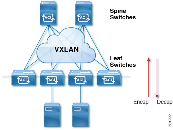
Figure 1. ACI Fabric
As traffic enters the fabric, ACI encapsulates and applies policy to it, forwards it as needed across the fabric through a spine switch (maximum two-hops),
and de-encapsulates it upon exiting the fabric. Within the fabric, ACI uses Intermediate System-to-Intermediate System Protocol (IS-IS) and Council of Oracle Protocol (COOP) for all forwarding
of endpoint to endpoint communications. This enables all ACI links to be active, equal cost multipath (ECMP) forwarding in
the fabric, and fast-reconverging. For propagating routing information between software defined networks within the fabric
and routers external to the fabric, ACI uses the Multiprotocol Border Gateway Protocol (MP-BGP).
VXLAN in ACI
VXLAN is an industry-standard protocol that extends Layer 2 segments over Layer 3 infrastructure to build Layer 2 overlay
logical networks. The ACI infrastructure Layer 2 domains reside in the overlay, with isolated broadcast and failure bridge domains. This approach allows
the data center network to grow without the risk of creating too large a failure domain.
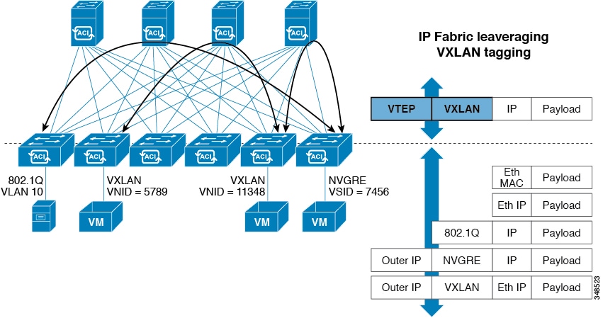
All traffic in the ACI fabric is normalized as VXLAN packets. At ingress, ACI encapsulates external VLAN, VXLAN, and NVGRE packets in a VXLAN packet. The following figure shows ACI encapsulation normalization.
Figure 2. ACI Encapsulation Normalization
Forwarding in the ACI fabric is not limited to or constrained by the encapsulation type or encapsulation overlay network. An ACI bridge domain forwarding policy can be defined to provide standard VLAN behavior where required.
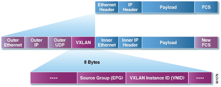
Because every packet in the fabric carries ACI policy attributes, ACI can consistently enforce policy in a fully distributed manner. ACI decouples application policy EPG identity from forwarding. The following illustration shows how the ACI VXLAN header identifies application policy within the fabric.
Figure 3. ACI VXLAN Packet Format
The ACI VXLAN packet contains both Layer 2 MAC address and Layer 3 IP address source and destination fields, which enables efficient
and scalable forwarding within the fabric. The ACI VXLAN packet header source group field identifies the application policy endpoint group (EPG) to which the packet belongs.
The VXLAN Instance ID (VNID) enables forwarding of the packet through tenant virtual routing and forwarding (VRF) domains
within the fabric. The 24-bit VNID field in the VXLAN header provides an expanded address space for up to 16 million unique
Layer 2 segments in the same network. This expanded address space gives IT departments and cloud providers greater flexibility
as they build large multitenant data centers.
VXLAN enables ACI to deploy Layer 2 virtual networks at scale across the fabric underlay Layer 3 infrastructure. Application endpoint hosts
can be flexibly placed in the data center network without concern for the Layer 3 boundary of the underlay infrastructure,
while maintaining Layer 2 adjacency in a VXLAN overlay network.
The ACI fabric provides tenant default gateway functionality that routes between the ACI fabric VXLAN networks. For each tenant, the fabric provides a virtual default gateway that spans all of the leaf switches
assigned to the tenant. It does this at the ingress interface of the first leaf switch connected to the endpoint. Each ingress
interface supports the default gateway interface. All of the ingress interfaces across the fabric share the same router IP
address and MAC address for a given tenant subnet.
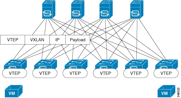
The ACI fabric decouples the tenant endpoint address, its identifier, from the location of the endpoint that is defined by its locator
or VXLAN tunnel endpoint (VTEP) address. Forwarding within the fabric is between VTEPs. The following figure shows decoupled
identity and location in ACI.
Figure 4. ACI Decouples Identity and Location
VXLAN uses VTEP devices to map tenant end devices to VXLAN segments and to perform VXLAN encapsulation and de-encapsulation.
Each VTEP function has two interfaces:
A switch interface on the local LAN segment to support local endpoint communication through bridging
An IP interface to the transport IP network
The IP interface has a unique IP address that identifies the VTEP device on the transport IP network known as the infrastructure
VLAN. The VTEP device uses this IP address to encapsulate Ethernet frames and transmit the encapsulated packets to the transport
network through the IP interface. A VTEP device also discovers the remote VTEPs for its VXLAN segments and learns remote MAC
Address-to-VTEP mappings through its IP interface.
The VTEP in ACI maps the internal tenant MAC or IP address to a location using a distributed mapping database. After the VTEP completes a
lookup, the VTEP sends the original data packet encapsulated in VXLAN with the destination address of the VTEP on the destination
leaf switch. The destination leaf switch de-encapsulates the packet and sends it to the receiving host. With this model, ACI
uses a full mesh, single hop, loop-free topology without the need to use the spanning-tree protocol to prevent loops.
The VXLAN segments are independent of the underlying network topology; conversely, the underlying IP network between VTEPs
is independent of the VXLAN overlay. It routes the encapsulated packets based on the outer IP address header, which has the
initiating VTEP as the source IP address and the terminating VTEP as the destination IP address.
The following figure shows how routing within the tenant is done.
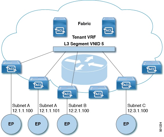
Figure 5. Layer 3 VNIDs Transport ACI Inter-subnet Tenant Traffic
For each tenant VRF in the fabric, ACI assigns a single L3 VNID. ACI transports traffic across the fabric according to the L3 VNID. At the egress leaf switch, ACI
routes the packet from the L3 VNID to the VNID of the egress subnet.
Traffic arriving at the fabric ingress that is sent to the ACI fabric default gateway is routed into the Layer 3 VNID. This provides very efficient forwarding in the fabric for traffic
routed within the tenant. For example, with this model, traffic between 2 VMs belonging to the same tenant, on the same physical
host, but on different subnets, only needs to travel to the ingress switch interface before being routed (using the minimal
path cost) to the correct destination.
To distribute external routes within the fabric, ACI route reflectors use multiprotocol BGP (MP-BGP). The fabric administrator provides the autonomous system (AS) number and
specifies the spine switches that become route reflectors.
Note
Cisco ACI does not support IP fragmentation. Therefore, when you configure Layer 3 Outside (L3Out) connections to external routers,
or Multi-Pod connections through an Inter-Pod Network (IPN), it is recommended that the interface MTU is set appropriately
on both ends of a link.
IGP Protocol Packets (EIGRP, OSPFv3) are constructed by components based on the Interface MTU size. In Cisco ACI, if the CPU MTU size is less than the Interface MTU size and if the constructed packet size is greater than the CPU MTU,
then the packet is dropped by the kernal, especially in IPv6. To avoid such control packet drops always configure the same
MTU values on both the control plane and on the interface.
On some platforms, such as Cisco ACI, Cisco NX-OS, and Cisco IOS, the configurable MTU value does not take into account the Ethernet headers (matching IP MTU,
and excluding the 14-18 Ethernet header size), while other platforms, such as IOS-XR, include the Ethernet header in the configured
MTU value. A configured value of 9000 results in a max IP packet size of 9000 bytes in Cisco ACI, Cisco NX-OS, and Cisco IOS, but results in a max IP packet size of 8986 bytes for an IOS-XR untagged interface.
For the appropriate MTU values for each platform, see the relevant configuration
guides.
We highly recommend that you test the MTU using CLI-based commands. For example, on
the Cisco NX-OS CLI, use a command such as ping 1.1.1.1 df-bit packet-size 9000 source-interface
ethernet 1/1.
WAN and Other External Networks
Networking
Domains
A fabric
administrator creates domain policies that configure ports, protocols, VLAN
pools, and encapsulation. These policies can be used exclusively by a single
tenant, or shared. Once a fabric administrator configures domains in the ACI
fabric, tenant administrators can associate tenant endpoint groups (EPGs) to
domains.
The following networking domain profiles can be configured:
VMM domain
profiles (vmmDomP) are required for virtual machine hypervisor
integration.
Physical domain
profiles (physDomP) are typically used for bare metal server
attachment and management access.
Bridged outside
network domain profiles (l2extDomP) are typically used to connect a bridged
external network trunk switch to a leaf switch in the ACI fabric.
Routed outside
network domain profiles (l3extDomP) are used to connect a router to a leaf
switch in the ACI fabric.
Fibre Channel domain profiles (fcDomP) are used to connect Fibre Channel VLANs and VSANs.
A domain is configured
to be associated with a VLAN pool. EPGs are then configured to use the VLANs
associated with a domain.
Note
EPG port and VLAN
configurations must match those specified in the domain infrastructure
configuration with which the EPG associates. If not, the APIC will raise a
fault. When such a fault occurs, verify that the domain infrastructure
configuration matches the EPG port and VLAN configurations.
Configuring Route
Reflectors
ACI fabric route reflectors use multiprotocol BGP (MP-BGP) to distribute external routes within the fabric. To enable route
reflectors in the ACI fabric, the fabric administrator must select the spine switches that will be the route reflectors, and
provide the autonomous system (AS) number. It is recommended to configure at least two spine nodes per pod as MP-BGP route
reflectors for redundancy.
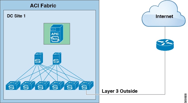
After route reflectors are enabled in the ACI fabric, administrators can configure connectivity to external networks through
leaf nodes using a component called Layer 3 Out (L3Out). A leaf node configured with an L3Out is called a border leaf. The
border leaf exchanges routes with a connected external device via a routing protocol specified in the L3Out. You can also
configure static routes via L3Outs.
After both L3Outs and spine route reflectors are deployed, border leaf nodes learn external routes via L3Outs, and those external
routes are distributed to all leaf nodes in the fabric via spine MP-BGP route reflectors.
Check the Verified Scalability Guide for Cisco APIC for your release to find the maximum number of routes supported by a leaf.
Router Peering and
Route Distribution
As shown in the figure
below, when the routing peer model is used, the leaf switch interface is
statically configured to peer with the external router’s routing protocol.
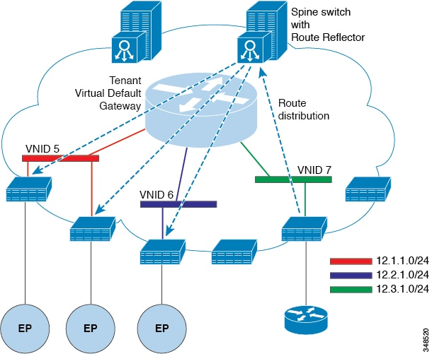
Figure 6. Router
Peering
The routes that are
learned through peering are sent to the spine switches. The spine switches act
as route reflectors and distribute the external routes to all of the leaf
switches that have interfaces that belong to the same tenant. These routes are
longest prefix match (LPM) summarized addresses and are placed in the leaf
switch's forwarding table with the VTEP IP address of the remote leaf switch
where the external router is connected. WAN routes have no forwarding proxy. If
the WAN routes do not fit in the leaf switch's forwarding table, the traffic is
dropped. Because the external router is not the default gateway, packets from
the tenant endpoints (EPs) are sent to the default gateway in the ACI fabric.
Route Import and Export, Route Summarization, and Route Community Match
Subnet route export or import configuration options can be specified according to the scope and aggregation options described
below.
For routed subnets, the following scope options are available:
Export Route Control Subnet—Controls the export route direction.
Import Route Control Subnet—Controls the import route direction.
Note
Import route control is supported for BGP and OSPF, but not EIGRP.
External Subnets for the External EPG (Security Import Subnet)—Specifies which external subnets have contracts applied as
part of a specific External Network Instance Profile (l3extInstP). For a subnet under the l3extInstP to be classified as an External EPG, the scope on the subnet should be set to "import-security". Subnets of this scope determine
which IP addresses are associated with the l3extInstP. Once this is determined, contracts determine with which other EPGs that external subnet is allowed to communicate. For example,
when traffic enters the ACI switch on the Layer 3 External Outside Network (L3extOut), a lookup occurs to determine which source IP addresses are associated with the l3extInstP. This action is performed based on Longest Prefix Match (LPM) so that more specific subnets take precedence over more general
subnets.
Shared Route Control Subnet— In a shared service configuration, only subnets that have this property enabled will be imported
into the consumer EPG Virtual Routing and Forwarding (VRF). It controls the route direction for shared services between VRFs.
Shared Security Import Subnet—Applies shared contracts to imported subnets. The default specification is External Subnets
for the External EPG.
Routed subnets can be aggregated. When aggregation is not set, the subnets are matched exactly. For example, if 11.1.0.0/16
is the subnet, then the policy will not apply to a 11.1.1.0/24 route, but it will apply only if the route is 11.1.0.0/16.
However, to avoid a tedious and error prone task of defining all the subnets one by one, a set of subnets can be aggregated
into one export, import or shared routes policy. At this time, only 0/0 subnets can be aggregated. When 0/0 is specified with
aggregation, all the routes are imported, exported, or shared with a different VRF, based on the selection option below:
Aggregate Export—Exports all transit routes of a VRF (0/0 subnets).
Aggregate Import—Imports all incoming routes of given L3 peers (0/0 subnets).
Note
Aggregate import route control is supported for BGP and OSPF, but not for
EIGRP.
Aggregate Shared Routes—If a route is learned in one VRF but needs to be advertised to another VRF, the routes can be shared
by matching the subnet exactly, or can be shared in an aggregate way according to a subnet mask. For aggregate shared routes,
multiple subnet masks can be used to determine which specific route groups are shared between VRFs. For example, 10.1.0.0/16
and 12.1.0.0/16 can be specified to aggregate these subnets. Or, 0/0 can be used to share all subnet routes across multiple
VRFs.
Note
Routes shared between VRFs function correctly on Generation 2 switches (Cisco Nexus N9K switches with "EX" or "FX" on the
end of the switch model name, or later; for example, N9K-93108TC-EX). On Generation 1 switches, however, there may be dropped
packets with this configuration, because the physical ternary content-addressable memory (TCAM) tables that store routes do
not have enough capacity to fully support route parsing.
Route summarization simplifies route tables by replacing many specific addresses with an single address. For example, 10.1.1.0/24,
10.1.2.0/24, and 10.1.3.0/24 are replaced with 10.1.0.0/16. Route summarization policies enable routes to be shared efficiently
among border leaf switches and their neighbor leaf switches. BGP, OSPF, or EIGRP route summarization policies are applied
to a bridge domain or transit subnet. For OSPF, inter-area and external route summarization are supported. Summary routes
are exported; they are not advertised within the fabric. In the example above, when a route summarization policy is applied,
and an EPG uses the 10.1.0.0/16 subnet, the entire range of 10.1.0.0/16 is shared with all the neighboring leaf switches.
Note
When two L3extOut policies are configured with OSPF on the same leaf switch, one regular and another for the backbone, a route summarization
policy configured on one L3extOut is applied to both L3extOut policies because summarization applies to all areas in the VRF.
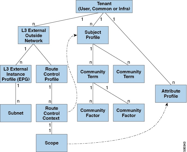
As illustrated in the figure below, route control profiles derive route maps according to prefix-based and community-based
matching.
Figure 7. Route Community Matching
The route control profile (rtctrtlProfile) specifies what is allowed. The Route Control Context specifies what to match, and the scope specifies what to set. The subject
profile contains the community match specifications, which can be used by multiple l3extOut instances. The subject profile (SubjP) can contain multiple community terms each of which contains one or more community factors (communities). This arrangement
enables specifying the following boolean operations:
Logical or among multiple community terms
Logical and among multiple community factors
For example, a community term called northeast could have multiple communities that each include many routes. Another community
term called southeast could also include many different routes. The administrator could choose to match one, or the other,
or both. A community factor type can be regular or extended. Care should be taken when using extended type community factors,
to ensure there are no overlaps among the specifications.
The scope portion of the route control profile references the attribute profile (rtctrlAttrP) to specify what set-action to apply, such as preference, next hop, community, and so forth. When routes are learned from
an l3extOut, route attributes can be modified.
The figure above illustrates the case where an l3extOut contains a rtctrtlProfile. A rtctrtlProfile can also exist under the tenant. In this case, the l3extOut has an interleak relation policy (L3extRsInterleakPol) that associates it with the rtctrtlProfile under the tenant. This configuration enables reusing the rtctrtlProfile for multiple l3extOut connections. It also enables keeping track of the routes the fabric learns from OSPF to which it gives BGP attributes (BGP
is used within the fabric). A rtctrtlProfile defined under an L3extOut has a higher priority than one defined under the tenant.
The rtctrtlProfile has two modes: combinable, and global. The default combinable mode combines pervasive subnets (fvSubnet) and external subnets (l3extSubnet) with the match/set mechanism to render the route map. The global mode applies to all subnets within the tenant, and overrides
other policy attribute settings. A global rtctrtlProfile provides permit-all behavior without defining explicit (0/0) subnets. A global rtctrtlProfile is used with non-prefix based match rules where matching is done using different subnet attributes such as community, next
hop, and so on. Multiple rtctrtlProfile policies can be configured under a tenant.
rtctrtlProfile policies enable enhanced default import and default export route control. Layer 3 Outside networks with aggregated import
or export routes can have import/export policies that specify supported default-export and default–import, and supported 0/0
aggregation policies. To apply a rtctrtlProfile policy on all routes (inbound or outbound), define a global default rtctrtlProfile that has no match rules.
Note
While multiple l3extOut connections can be configured on one switch, all Layer 3 outside networks configured on a switch must use the same rtctrtlProfile because a switch can have only one route map.
The protocol interleak and redistribute policy controls externally learned route sharing with ACI fabric BGP routes. Set attributes
are supported. Such policies are supported per L3extOut, per node, or per VRF. An interleak policy applies to routes learned by the routing protocol in the L3extOut. Currently, interleak and redistribute policies are supported for OSPF v2 and v3. A route control policy rtctrtlProfile has to be defined as global when it is consumed by an interleak policy.
ACI Route
Redistribution
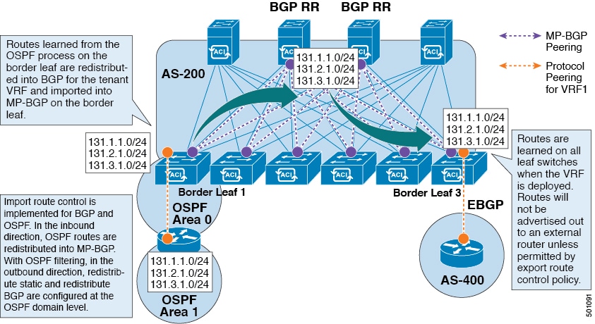
Figure 8. ACI Route Redistribution
The routes that
are learned from the OSPF process on the border leaf are redistributed into BGP
for the tenant VRF and they are imported into MP-BGP on the border leaf.
Import route control is supported for BGP and OSPF, but not for EIGRP.
Export route control is supported for OSPF, BGP, and EIGRP.
The routes are
learned on the border leaf where the VRF is deployed. The routes are not
advertised to the External Layer 3 Outside connection unless it is permitted by
the export route control.
Note
When a subnet for a bridge domain/EPG is set to Advertise Externally, the subnet is programmed as a static route on a border
leaf. When the static route is advertised, it is redistributed into the EPG's Layer 3 outside network routing protocol as
an external network, not injected directly into the routing protocol.
Route Distribution
Within the ACI Fabric
ACI supports the following routing mechanisms:
Static Routes
OSPFv2 (IPv4)
OSPFv3 (IPv6)
iBGP
eBGP (IPv4 and IPv6)
EIGRP (IPv4 and IPv6) protocols
ACI supports the
VRF-lite implementation when connecting to the external routers. Using
sub-interfaces, the border leaf can provide Layer 3 outside connections for the
multiple tenants with one physical interface. The VRF-lite implementation
requires one protocol session per tenant.
Within the ACI fabric,
Multiprotocol BGP (MP-BGP) is implemented between the leaf and the spine
switches to propagate the external routes within the ACI fabric. The BGP route
reflector technology is deployed in order to support a large number of leaf
switches within a single fabric. All of the leaf and spine switches are in one
single BGP Autonomous System (AS). Once the border leaf learns the external
routes, it can then redistribute the external routes of a given VRF to an
MP-BGP address family VPN version 4 or VPN version 6. With address family VPN
version 4, MP-BGP maintains a separate BGP routing table for each VRF. Within
MP-BGP, the border leaf advertises routes to a spine switch, that is a BGP
route reflector. The routes are then propagated to all the leaves where the
VRFs (or private network in the APIC GUI’s terminology) are instantiated.
Note
In the 3.2(7) release, the EIGRP metric is now carried over the BGP VPNv4 address
family using extended communities.
External Layer 3
Outside Connection Types
ACI supports the
following External Layer 3 Outside connection options:
Static Routing
(supported for IPv4 and IPv6)
OSPFv2 for normal
and NSSA areas (IPv4)
OSPFv3 for normal
and NSSA areas (IPv6)
iBGP (IPv4 and
IPv6)
eBGP (IPv4 and
IPv6)
EIGRP (IPv4 and IPv6)
The External Layer 3
Outside connections are supported on the following interfaces:
Layer 3 Routed
Interface
Subinterface with 802.1Q tagging - With subinterface, you can use the same physical interface to provide a Layer 2 outside
connection for multiple private networks.
Switched Virtual
Interface (SVI) - With an SVI interface, the same physical interface that
supports Layer 2 and Layer 3 and the same physical interface can be used for a
Layer 2 outside connection and a Layer 3 outside connection.
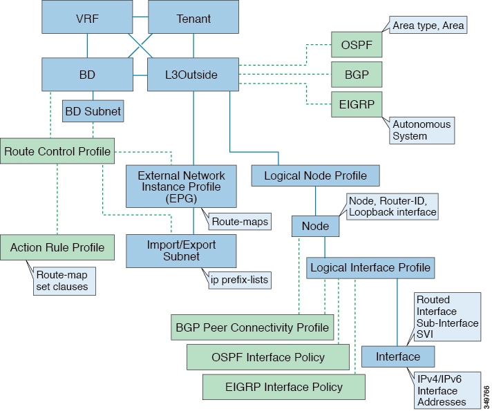
Figure 9. ACI Layer 3 Managed Objects
The managed objects
that are used for the L3Outside connections are:
Logical Node Profile: Profile where one or more nodes are defined for the External Layer 3 Outside connections. The configurations
of the router-IDs and the loopback interface are defined in the profile.
Note
Use the same router-ID for the same node across multiple External Layer 3 Outside connections.
Note
Within a single L3Out, a node can only be part of one Logical Node Profile. Configuring the node to be a part of multiple
Logical Node Profiles in a single L3Out might result in unpredictable behavior, such as having a loopback address pushed from
one Logical Node Profile but not from the other. Use more path bindings under the existing Logical Interface Profiles or create
a new Logical Interface Profile under the existing Logical Node Profile instead.
Logical Interface Profile: IP interface configuration for IPv4 and IPv6 interfaces. It is supported on the Route Interfaces,
Routed subinterfaces, and SVIs. The SVIs can be configured on physical ports, port-channels, or vPCs.
OSPF Interface Policy: Includes details such as OSPF Network Type and priority.
EIGRP Interface Policy: Includes details such as Timers and split horizon.
BGP Peer Connectivity Profile: The profile where most BGP peer settings, remote-as, local-as, and BGP peer connection options
are configured. You can associate the BGP peer connectivity profile with the logical interface profile or the loopback interface
under the node profile. This determines the update-source configuration for the BGP peering session.
External Network Instance Profile (EPG) (l3extInstP): The external EPG is also referred to as the prefix-based EPG or InstP.
The import and export route control policies, security import policies, and contract associations are defined in this profile.
You can configure multiple external EPGs under a single L3Out. You may use multiple external EPGs when a different route or
a security policy is defined on a single External Layer 3 Outside connections. An external EPG or multiple external EPGs combine
into a route-map. The import/export subnets defined under the external EPG associate to the IP prefix-list match clauses in
the route-map. The external EPG is also where the import security subnets and contracts are associated. This is used to permit
or drop traffic for this L3out.
Action Rules
Profile: The action rules profile is used to define the route-map set clauses
for the L3Out. The supported set clauses are the BGP communities (standard and
extended), Tags, Preference, Metric, and Metric type.
Route Control Profile: The route-control profile is used to reference the action rules profiles. This can be an ordered list
of action rules profiles. The Route Control Profile can be referenced by a tenant BD, BD subnet, external EPG, or external
EPG subnet.
There are more protocol settings for BGP, OSPF, and EIGRP L3Outs. These settings are configured per tenant in the ACI Protocol
Policies section in the GUI.
Note
When configuring policy enforcement between external EPGs (transit routing case), you must configure the second external EPG
(InstP) with the default prefix 0/0 for export route control, aggregate export, and external security. In addition, you must
exclude the preferred group, and you must use an any contract (or desired contract) between the transit InstPs.
About the Modes of
Configuring Layer 3 External Connectivity
Because APIC supports multiple user interfaces (UIs) for configuration, the potential exists for unintended interactions when
you create a configuration with one UI and later modify the configuration with another UI. This section describes considerations
for configuring Layer 3 external connectivity with the APIC NX-OS style CLI, when you may also be using other APIC user interfaces.
When you configure Layer 3 external connectivity with the APIC NX-OS style CLI, you have the choice of two modes:
Implicit mode, a simpler mode, is not compatible with the APIC GUI or the REST API.
Named (or Explicit) mode is compatible with the APIC GUI and the REST API.
In either case, the
configuration should be considered read-only in the incompatible UI.
How the Modes
Differ
In both modes, the
configuration settings are defined within an internal container object, the "L3
Outside" (or "L3Out"), which is an instance of the
l3extOut class
in the API. The main difference between the two modes is in the naming of this
container object instance:
Implicit mode—the naming of the container is implicit and does not appear in the CLI commands. The CLI creates and maintains
these objects internally.
Named mode—the naming is provided by the user. CLI commands in the Named Mode have an additional l3Out field. To configure the named L3Out correctly and avoid faults, the user is expected to understand the API object model for
external Layer 3 configuration.
Note
Except for the procedures in the Configuring Layer 3 External Connectivity Using the Named Mode section, this guide describes Implicit mode procedures.
Guidelines and
Restrictions
In the same APIC instance, both modes can be used together for configuring Layer 3 external connectivity with the following
restriction: The Layer 3 external connectivity configuration for a given combination of tenant, VRF, and leaf can be done
only through one mode.
For a given tenant VRF, the policy domain where the External-l3 EPG can be placed can be in either the Named mode or in the
Implicit mode. The recommended configuration method is to use only one mode for a given tenant VRF combination across all
the nodes where the given tenant VRF is deployed for Layer 3 external connectivity. The modes can be different across different
tenants or different VRFs and no restrictions apply.
In some cases, an incoming configuration to a Cisco APIC cluster will be validated against inconsistencies, where the validations
involve externally-visible configurations (northbound traffic through the L3Outs). An Invalid Configuration error message
will appear for those situations where the configuration is invalid.
The external Layer 3 features are supported in both configuration modes, with the following exception:
Route-peering and Route Health Injection (RHI) with a L4-L7 Service Appliance is supported only in the Named mode. The Named
mode should be used across all border leaf switches for the tenant VRF where route-peering is involved.
Layer 3 external network objects (l3extOut) created using the Implicit mode CLI procedures are identified by names starting
with “__ui_” and are marked as read-only in the GUI. The CLI partitions these external-l3 networks by function, such as interfaces,
protocols, route-map, and EPG. Configuration modifications performed through the REST API can break this structure, preventing
further modification through the CLI.
For the steps to remove such objects, see Troubleshooting Unwanted _ui_ Objects in the APIC Troubleshooting Guide.
Controls Enabled for Subnets Configured under the L3Out Network Instance Profile
The following controls can be enabled for the subnets that are configured under the L3Out Network Instance Profile.
Table 1. Route Control Options
Route control Setting
Use
Options
Export Route Control
Controls which external networks are advertised out of the fabric using route-maps and IP prefix lists. An IP prefix list
is created on the BL switch for each subnet that is defined. The export control policy is enabled by default and is supported
for BGP, EIGRP, and OSPF.
Specific match (prefix and prefix length).
Import Route Control
Controls the subnets that are allowed into the fabric. Can include set and match rules to filter routes. Supported for BGP
and OSPF, but not for EIGRP. If you enable the import control policy for an unsupported protocol, it is automatically ignored.
The import control policy is not enabled by default, but you can enable it on the Create Routed Outside panel. On the Identity tab, enable Route Control Enforcement: Import.
Specific match (prefix and prefix length) .
Security Import Subnet
Used to permit the packets to flow between two prefix-based EPGs. Implemented with ACLs.
Uses the ACL match prefix or wildcard match rules.
Aggregate Export
Used to allow all prefixes to be advertised to the external peers. Implemented with the 0.0.0.0/ le 32 IP prefix-list.
Only supported for 0.0.0.0/0 subnet (all prefixes).
Aggregate Import
Used to allow all prefixes that are inbound from an external BGP peer. Implemented with the 0.0.0.0/0 le 32 IP prefix-list.
Only supported for the 0.0.0.0/0 subnet (all prefixes).
You may prefer to advertise all the transit routes out of an L3Out connection. In this case, use the aggregate export option
with the prefix 0.0.0.0/0. Using this aggregate export option creates an IP prefix-list entry (permit 0.0.0.0/0 le 32) that
the APIC system uses as a match clause in the export route-map. Use the show route-map <outbound route-map> and show ip prefix-list <match-clause> commands to view the output.
If you enable aggregate shared routes, if a route learned in one VRF must be advertised to another VRF, the routes can be
shared by matching the subnet exactly, or they can be shared by using an aggregate subnet mask. Multiple subnet masks can
be used to determine which specific route groups are shared between VRFs. For example, 10.1.0.0/16 and 12.1.0.0/16 can be
specified to aggregate these subnets. Or, 0/0 can be used to share all subnet routes across multiple VRFs.
Note
Routes shared between VRFs function correctly on Generation 2 switches (Cisco Nexus N9K switches with "EX" or "FX" on the
end of the switch model name, or later; for example, N9K-93108TC-EX). On Generation 1 switches, however, there may be dropped
packets with this configuration, because the physical ternary content-addressable memory (TCAM) tables that store routes do
not have enough capacity to fully support route parsing.
ACI Layer 3 Outside
Network Workflows
This workflow provides an overview of the steps required to configure a Layer 3 Outside (L3Out) network connection.
Figure 10. Layer 3
outside network connection
1.
Prerequisites
Ensure that you have read/write access privileges to the infra security domain.
Ensure that the target leaf switches with the necessary interfaces are available.
Configure a Layer 3 Outside Network
Choose which of these L3Out scenarios you will use:
For an L3Out that will be consumed within a single tenant, follow the instructions for configuring BGP or OSPF.
For an L3Out that will be consumed (shared) among multiple tenants, follow the "Shared Layer 3 Out" guidelines.
For an L3Out transit routing use case, follow ACI transit routing instructions.
Note: This feature requires APIC release 1.2(1x) or later.

 Feedback