A route transit is defined to import traffic through a Layer 3 outside network L3extOut profile (l3extInstP), where it is to be imported. A different route transit is defined to export traffic through another l3extInstP where it is to be exported.
Since multiple
l3extOut policies can be deployed on a single node or
multiple nodes in the fabric, a variety of protocol combinations are supported.
Every protocol combination can be deployed on a single node using multiple
l3extOut policies or multiple nodes using multiple
l3extOut policies. Deployments of more than two
protocols in different
l3extOut policies in the fabric are supported.
Export route-maps are made up of prefix-list matches. Each prefix-list consists of bridge domain (BD) public subnet prefixes
in the VRF and the export prefixes that need to be advertised outside.
Route control policies are defined in an l3extOut policy and controlled by properties and relations associated with the l3extOut. APIC uses the enforceRtctrl property of the l3extOut to enforce route control directions. The default is to enforce control on export and allow all on import. Imported and exported
routes (l3extSubnets), are defined in the l3extInstP. The default scope for every route is import. These are the routes and prefixes which form a prefix-based EPG.
All the import routes form the import route map and are used by BGP and OSPF to control import. All the export routes form
the export route map used by OSPF and BGP to control export.
Import and export route control policies are defined at different levels. All IPv4 policy levels are supported for IPv6. Extra
relations that are defined in the l3extInstP and l3extSubnet MOs control import.
Default route leak is
enabled by defining the
l3extDefaultRouteLeakP MO under the
l3extOut.
l3extDefaultRouteLeakP can have Virtual Routing and Forwarding (VRF) scope or L3extOut scope per area for OSPF and per peer for BGP.
The following set rules provide route control:
-
rtctrlSetPref
-
rtctrlSetRtMetric
-
rtctrlSetRtMetricType
Additional syntax for the rtctrlSetComm MO includes the following:
-
no-advertise
-
no-export
-
no-peer
BGP
The ACI fabric
supports BGP peering with external routers. BGP peers are associated with an
l3extOut policy and multiple BGP peers can be
configured per
l3extOut. BGP can be enabled at the
l3extOut level by defining the
bgpExtP MO under an
l3extOut.

Note
|
Although the l3extOut policy contains the routing protocol (for example, BGP with its related VRF), the L3Out interface profile contains the necessary
BGP interface configuration details. Both are needed to enable BGP.
|
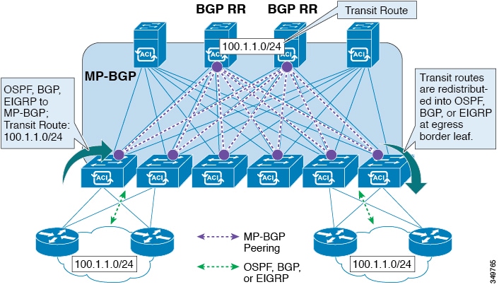
BGP peer reachability can be through OSPF, EIGRP, a connected interface, static routes, or a loopback. iBGP or eBGP can be
used for peering with external routers. The BGP route attributes from the external router are preserved since MP-BGP is used
for distributing the external routes in the fabric. BGP enables IPv4 and/or IPv6 address families for the VRF associated with
an l3extOut. The address family to enable on a switch is determined by the IP address type defined in bgpPeerP policies for the l3extOut. The policy is optional; if not defined, the default will be used. Policies can be defined for a tenant and used by a VRF
that is referenced by name.
You must define at least one peer policy to enable the protocol on each border leaf (BL) switch. A peer policy can be defined
in two places:
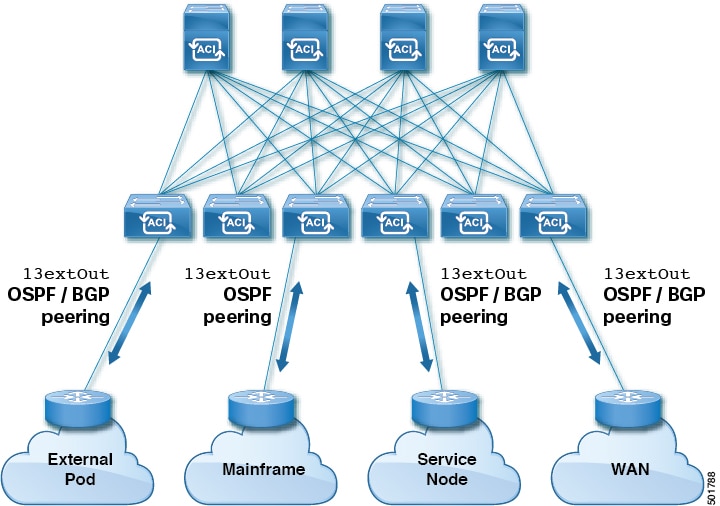
OSPF
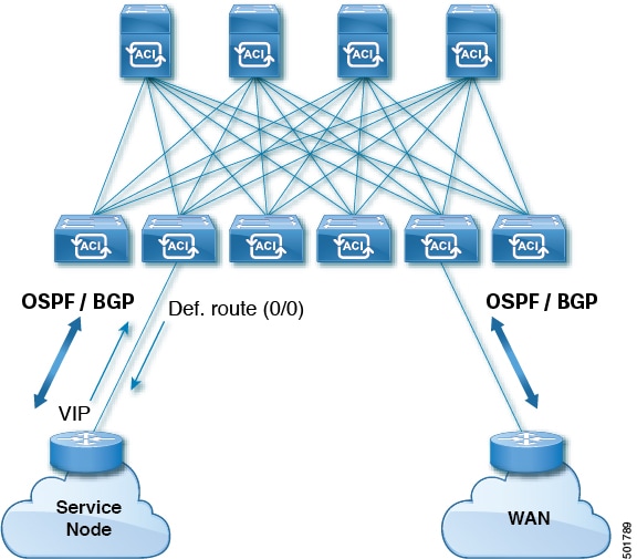
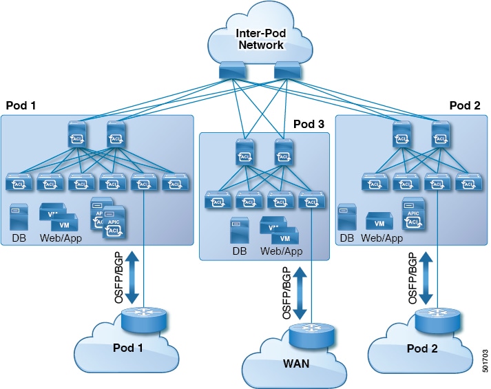
Various host types require OSPF to enable connectivity and provide redundancy. These include mainframe devices, external pods
and service nodes that use the ACI fabric as a Layer 3 transit within the fabric and to the WAN. Such external devices peer
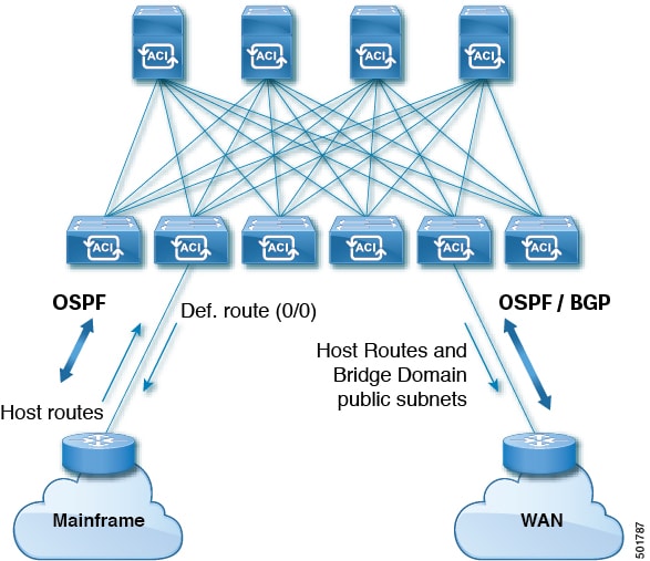
with the fabric through a nonborder leaf switch running OSPF. Configure the OSPF area as an NSSA (stub) area to enable it
to receive a default route and not participate in full-area routing. Typically, existing routing deployments avoid configuration
changes, so a stub area configuration is not mandated.
You enable OSPF by configuring an ospfExtP managed object under an l3extOut. OSPF IP address family versions configured on the BL switch are determined by the address family that is configured in
the OSPF interface IP address.
Note
|
Although the l3extOut policy contains the routing protocol (for example, OSPF with its related VRF and area ID), the Layer 3 external interface
profile contains the necessary OSPF interface details. Both are needed to enable OSPF.
|
You configure OSPF policies at the VRF level by using the fvRsCtxToOspfCtxPol relation, which you can configure per address family. If you do not configured it, default parameters are used.
You configure the OSPF area in the ospfExtP managed object, which also exposes IPv6 the required area properties.
 Feedback