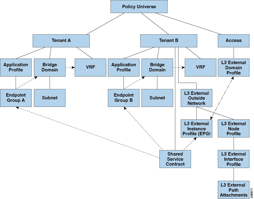
Shared Services

This chapter contains the following sections:

Shared Layer 3 Out

A shared Layer 3 Outside (L3Out or l3extOut) configuration provides routed connectivity to an external network as a shared service across VRF instances or tenants. An external EPG instance profile (external EPG or l3extInstP) in an L3Out provides the configurations to control which routes can be shared from both the routing perspective and contract perspective. A contract under an external EPG determines to which VRF instances or tenants those routes should be leaked.

An L3Out can be provisioned as a shared service in any tenant (user, common, infra, or mgmt). An EPG in any tenant can use a shared services contract to connect with an external EPG regardless of where in the fabric that external EPG is provisioned. This simplifies the provisioning of routed connectivity to external networks; multiple tenants can share a single external EPG for routed connectivity to external networks. Sharing an external EPG is more efficient because it consumes only one session on the switch regardless of how many EPGs use the single shared external EPG.

The figure below illustrates the major policy model objects that are configured for a shared external EPG.
Figure 1. Shared L3Out Policy Model


Take note of the following guidelines and limitations for shared L3Out network configurations:

  • No tenant limitations: Tenants A and B can be any kind of tenant (user, common, infra, mgmt). The shared external EPG does not have to be in the common tenant.

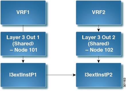
  • Flexible placement of EPGs: EPG A and EPG B in the illustration above are in different tenants. EPG A and EPG B could use the same bridge domain and VRF instance, but they are not required to do so. EPG A and EPG B are in different bridge domains and different VRF instances but still share the same external EPG.

  • A subnet can be private, public, or shared. A subnet that is to be advertised into a consumer or provider EPG of an L3Out must be set to shared. A subnet that is to be exported to an L3Out must be set to public.

  • The shared service contract is exported from the tenant that contains the external EPG that provides shared L3Out network service. The shared service contract is imported into the tenants that contain the EPGs that consume the shared service.

  • Do not use taboo contracts with a shared L3Out; this configuration is not supported.

  • The external EPG as a shared service provider is supported, but only with non-external EPG consumers (where the L3Out EPG is the same as the external EPG).

  • Traffic Disruption (Flap): When an external EPG is configured with an external subnet of 0.0.0.0/0 with the scope property of the external EPG subnet set to shared route control (shared-rctrl), or shared security (shared-security), the VRF instance is redeployed with a global pcTag. This will disrupt all the external traffic in that VRF instance (because the VRF instance is redeployed with a global pcTag).

  • Prefixes for a shared L3Out must to be unique. Multiple shared L3Out configurations with the same prefix in the same VRF instance will not work. Be sure that the external subnets (external prefixes) that are advertised into a VRF instance are unique (the same external subnet cannot belong to multiple external EPGs). An L3Out configuration (for example, named L3Out1) with prefix1 and a second L3Out configuration (for example, named L3Out2) also with prefix1 belonging to the same VRF instance will not work (because only 1 pcTag is deployed).

  • Different behaviors of L3Out are possible when configured on the same leaf switch under the same VRF instance. The two possible scenarios are as follows:

    • Scenario 1 has an L3Out with an SVI interface and two subnets (10.10.10.0/24 and 0.0.0.0/0) defined. If ingress traffic on the L3Out network has the matching prefix 10.10.10.0/24, then the ingress traffic uses the external EPG pcTag. If ingress traffic on the L3Out network has the matching default prefix 0.0.0.0/0, then the ingress traffic uses the external bridge pcTag.

    • Scenario 2 has an L3Out using a routed or routed-sub-interface with two subnets (10.10.10.0/24 and 0.0.0.0/0) defined. If ingress traffic on the L3Out network has the matching prefix 10.10.10.0/24, then the ingress traffic uses the external EPG pcTag. If ingress traffic on the L3Out network has the matching default prefix 0.0.0.0/0, then the ingress traffic uses the VRF instance pcTag.

    • As a result of these described behaviors, the following use cases are possible if the same VRF instance and same leaf switch are configured with L3Out-A and L3Out-B using an SVI interface:

      Case 1 is for L3Out-A: This external EPG has two subnets defined: 10.10.10.0/24 and 0.0.0.0/1. If ingress traffic on L3Out-A has the matching prefix 10.10.10.0/24, it uses the external EPG pcTag and contract-A, which is associated with L3Out-A. When egress traffic on L3Out-A has no specific match found, but there is a maximum prefix match with 0.0.0.0/1, it uses the external bridge domain pcTag and contract-A.

      Case 2 is for L3Out-B: This external EPG has one subnet defined: 0.0.0.0/0. When ingress traffic on L3Out-B has the matching prefix10.10.10.0/24 (which is defined under L3Out-A), it uses the external EPG pcTag of L3Out-A and the contract-A, which is tied with L3Out-A. It does not use contract-B, which is tied with L3Out-B.

  • Traffic not permitted: Traffic is not permitted when an invalid configuration sets the scope of the external subnet to shared route control (shared-rtctrl) as a subset of a subnet that is set to shared security (shared-security). For example, the following configuration is invalid:

    • shared rtctrl: 10.1.1.0/24, 10.1.2.0/24

    • shared security: 10.1.0.0/16

    In this case, ingress traffic on a non-border leaf with a destination IP of 10.1.1.1 is dropped, since prefixes 10.1.1.0/24 and 10.1.2.0/24 are installed with a drop rule. Traffic is not permitted. Such traffic can be enabled by revising the configuration to use the shared-rtctrl prefixes as shared-security prefixes as well.

  • Inadvertent traffic flow: Prevent inadvertent traffic flow by avoiding the following configuration scenarios:

    • Case 1 configuration details:

      • A L3Out network configuration (for example, named L3Out-1) with VRF1 is called provider1.

      • A second L3Out network configuration (for example, named L3Out-2) with VRF2 is called provider2.

      • L3Out-1 VRF1 advertises a default route to the Internet, 0.0.0.0/0, which enables both shared-rtctrl and shared-security.

      • L3Out-2 VRF2 advertises specific subnets to DNS and NTP, 192.0.0.0/8, which enables shared-rtctrl.

      • L3Out-2 VRF2 has specific subnet 192.1.0.0/16, which enables shared-security.

      • Variation A: EPG traffic goes to multiple VRF instances.

        • Communications between EPG1 and L3Out-1 is regulated by an allow_all contract.

        • Communications between EPG1 and L3Out-2 is regulated by an allow_all contract.

          Result: Traffic from EPG1 to L3Out-2 also goes to 192.2.x.x.

      • Variation B: An EPG conforms to the allow_all contract of a second shared L3Out network.

        • Communications between EPG1 and L3Out-1 is regulated by an allow_all contract.

        • Communications between EPG1 and L3Out-2 is regulated by an allow_icmp contract.

          Result: Traffic from EPG1 to L3Out-2 to 192.2.x.x conforms to the allow_all contract.

    • Case 2 configuration details:

      • An external EPG has one shared prefix and other non-shared prefixes.

      • Traffic coming in with src = non-shared is allowed to go to the EPG.

        • Variation A: Unintended traffic goes through an EPG.

          External EPG traffic goes through an L3Out that has these prefixes:

          • 192.0.0.0/8 = import-security, shared-rtctrl

          • 192.1.0.0/16 = shared-security

          • The EPG has 1.1.0.0/16 = shared.

          Result: Traffic going from 192.2.x.x also goes through to the EPG.

        • Variation B: Unintended traffic goes through an EPG. Traffic coming in a shared L3Out can go through the EPG.

          • The shared L3Out VRF instance has an EPG with pcTag = prov vrf and a contract set to allow_all.

          • The EPG <subnet> = shared.

          Result: The traffic coming in on the L3Out can go through the EPG.

Layer 3 Out to Layer 3 Out Inter-VRF Leaking

Starting with Cisco APIC release 2.2(2e) , when there are two Layer 3 Outs in two different VRFs, inter-VRF leaking is supported.

For this feature to work, the following conditions must be satisfied:

  • A contract between the two Layer 3 Outs is required.

  • Routes of connected and transit subnets for a Layer 3 Out are leaked by enforcing contracts (L3Out-L3Out as well as L3Out-EPG) and without leaking the dynamic or static routes between VRFs.

  • Dynamic or static routes are leaked for a Layer 3 Out by enforcing contracts (L3Out-L3Out as well as L3Out-EPG) and without advertising directly connected or transit routes between VRFs.

  • Shared Layer 3 Outs in different VRFs can communicate with each other.

  • There is no associated L3Out required for the bridge domain. When an Inter-VRF shared L3Out is used, it is not necessary to associate the user tenant bridge domains with the L3Out in tenant common. If you had a tenant-specific L3Out, it would still be associated to your bridge domains in your respective tenants.

  • Two Layer 3 Outs can be in two different VRFs, and they can successfully exchange routes.

  • This enhancement is similar to the Application EPG to Layer 3 Out inter-VRF communications. The only difference is that instead of an Application EPG there is another Layer 3 Out. Therefore, in this case, the contract is between two Layer 3 Outs.

In the following figure, there are two Layer 3 Outs with a shared subnet. There is a contract between the Layer 3 external instance profile (l3extInstP) in both the VRFs. In this case, the Shared Layer 3 Out for VRF1 can communicate with the Shared Layer 3 Out for VRF2.

Figure 2. Shared Layer 3 Outs Communicating Between Two VRFs

Configuring Two Shared Layer 3 Outs in Two VRFs Using REST API

The following REST API configuration example that displays how two shared Layer 3 Outs in two VRFs communicate.

Procedure


Step 1

Configure the provider Layer 3 Out.

Example:

<tenant name=“t1_provider”>
<fvCtx name=“VRF1">
<l3extOut name="T0-o1-L3OUT-1">
                <l3extRsEctx tnFvCtxName="o1"/>
                <ospfExtP areaId='60'/>
                <l3extInstP name="l3extInstP-1">
                <fvRsProv tnVzBrCPName="vzBrCP-1">
                </fvRsProv>
                <l3extSubnet ip="192.168.2.0/24" scope=“shared-rtctrl, shared-security" aggregate=""/>
                </l3extInstP>
</l3extOut>
</tenant>

Step 2

Configure the consumer Layer 3 Out.

Example:

<tenant name=“t1_consumer”>
<fvCtx name=“VRF2">
<l3extOut name="T0-o1-L3OUT-1">
                <l3extRsEctx tnFvCtxName="o1"/>
                <ospfExtP areaId=‘70'/>
                <l3extInstP name="l3extInstP-2">
                <fvRsCons tnVzBrCPName="vzBrCP-1">
                </fvRsCons>
                <l3extSubnet ip="199.16.2.0/24" scope=“shared-rtctrl, shared-security"          aggregate=""/>
                </l3extInstP>
</l3extOut>
</tenant>

Configuring Shared Layer 3 Out Inter-VRF Leaking Using the NX-OS Style CLI - Named Example

Procedure

  Command or Action Purpose

Step 1

Enter the configure mode.

Example:

apic1# configure

Step 2

Configure the provider Layer 3 Out.

Example:

apic1(config)# tenant t1_provider
apic1(config-tenant)# external-l3 epg l3extInstP-1 l3out T0-o1-L3OUT-1
apic1(config-tenant-l3ext-epg)# vrf member VRF1
apic1(config-tenant-l3ext-epg)# match ip 192.168.2.0/24 shared
apic1(config-tenant-l3ext-epg)# contract provider vzBrCP-1
apic1(config-tenant-l3ext-epg)# exit
apic1(config-tenant)# exit
apic1(config)# leaf 101
apic1(config-leaf)# vrf context tenant t1_provider vrf VRF1 l3out T0-o1-L3OUT-1
apic1(config-leaf-vrf)# route-map T0-o1-L3OUT-1_shared
apic1(config-leaf-vrf-route-map)# ip prefix-list l3extInstP-1 permit 192.168.2.0/24
apic1(config-leaf-vrf-route-map)# match prefix-list l3extInstP-1
apic1(config-leaf-vrf-route-map-match)# exit
apic1(config-leaf-vrf-route-map)# exit
apic1(config-leaf-vrf)# exit
apic1(config-leaf)# exit

Step 3

Configure the consumer Layer 3 Out.

Example:

apic1(config)# tenant t1_consumer
apic1(config-tenant)# external-l3 epg l3extInstP-2 l3out T0-o1-L3OUT-1
apic1(config-tenant-l3ext-epg)# vrf member VRF2
apic1(config-tenant-l3ext-epg)# match ip 199.16.2.0/24 shared
apic1(config-tenant-l3ext-epg)# contract consumer vzBrCP-1 imported
apic1(config-tenant-l3ext-epg)# exit
apic1(config-tenant)# exit
apic1(config)# leaf 101
apic1(config-leaf)# vrf context tenant t1_consumer vrf VRF2 l3out T0-o1-L3OUT-1
apic1(config-leaf-vrf)# route-map T0-o1-L3OUT-1_shared
apic1(config-leaf-vrf-route-map)# ip prefix-list l3extInstP-2 permit 199.16.2.0/24
apic1(config-leaf-vrf-route-map)# match prefix-list l3extInstP-2
apic1(config-leaf-vrf-route-map-match)# exit
apic1(config-leaf-vrf-route-map)# exit
apic1(config-leaf-vrf)# exit
apic1(config-leaf)# exit
apic1(config)#

Configuring Shared Layer 3 Out Inter-VRF Leaking Using the NX-OS Style CLI - Implicit Example

Procedure

  Command or Action Purpose

Step 1

Enter the configure mode.

Example:

apic1# configure

Step 2

Configure the provider tenant and VRF.

Example:

apic1(config)# tenant t1_provider
apic1(config-tenant)# vrf context VRF1
apic1(config-tenant-vrf)# exit
apic1(config-tenant)# exit

Step 3

Configure the consumer tenant and VRF.

Example:

apic1(config)# tenant t1_consumer
apic1(config-tenant)# vrf context VRF2
apic1(config-tenant-vrf)# exit
apic1(config-tenant)# exit

Step 4

Configure the contract.

Example:

apic1(config)# tenant t1_provider
apic1(config-tenant)# contract vzBrCP-1 type permit
apic1(config-tenant-contract)# scope exportable
apic1(config-tenant-contract)# export to tenant t1_consumer
apic1(config-tenant-contract)# exit

Step 5

Configure the provider External Layer 3 EPG.

Example:

apic1(config-tenant)# external-l3 epg l3extInstP-1
apic1(config-tenant-l3ext-epg)# vrf member VRF1
apic1(config-tenant-l3ext-epg)# match ip 192.168.2.0/24 shared
apic1(config-tenant-l3ext-epg)# contract provider vzBrCP-1
apic1(config-tenant-l3ext-epg)# exit
apic1(config-tenant)# exit

Step 6

Configure the provider export map.

Example:

apic1(config)# leaf 101
apic1(config-leaf)# vrf context tenant t1_provider vrf VRF1 
apic1(config-leaf-vrf)# route-map map1
apic1(config-leaf-vrf-route-map)# ip prefix-list p1 permit 192.168.2.0/24
apic1(config-leaf-vrf-route-map)# match prefix-list p1
apic1(config-leaf-vrf-route-map-match)# exit
apic1(config-leaf-vrf-route-map)# exit
apic1(config-leaf-vrf)# export map map1
apic1(config-leaf-vrf)# exit
apic1(config-leaf)# exit

Step 7

Configure the consumer external Layer 3 EPG.

Example:

apic1(config)# tenant t1_consumer
apic1(config-tenant)# external-l3 epg l3extInstP-2
apic1(config-tenant-l3ext-epg)# vrf member VRF2
apic1(config-tenant-l3ext-epg)# match ip 199.16.2.0/24 shared
apic1(config-tenant-l3ext-epg)# contract consumer vzBrCP-1 imported
apic1(config-tenant-l3ext-epg)# exit
apic1(config-tenant)# exit

Step 8

Configure the consumer export map.

Example:

apic1(config)# leaf 101
apic1(config-leaf)# vrf context tenant t1_consumer vrf VRF2
apic1(config-leaf-vrf)# route-map map2
apic1(config-leaf-vrf-route-map)# ip prefix-list p2 permit 199.16.2.0/24
apic1(config-leaf-vrf-route-map)# match prefix-list p2
apic1(config-leaf-vrf-route-map-match)# exit
apic1(config-leaf-vrf-route-map)# exit
apic1(config-leaf-vrf)# export map map2
apic1(config-leaf-vrf)# exit
apic1(config-leaf)# exit
apic1(config)#

Configuring Shared Layer 3 Out Inter-VRF Leaking Using the Advanced GUI

Before you begin

The contract label to be used by the consumer and provider is already created.

Procedure


Step 1

On the menu bar, choose Tenants > Add Tenant.

Step 2

In the Create Tenant dialog box, enter a tenant name for the provider.

Step 3

In the VRF Name field, enter a VRF name for the provider.

Step 4

In the Navigation pane, under the new tenant name, navigate to External Routed Networks.

Step 5

In the Work pane canvas, drag the L3 Out icon to associate it with the new VRF that you created.

Step 6

In the Create Routed Outside dialog box, perform the following actions:

  1. In the Name field, enter a name for the Layer 3 Routed Outside.

  2. Click Next to go to the Step 2 > External EPG Networks dialog box.

  3. Expand External EPG networks.

Step 7

In the Create External Network dialog box, perform the following actions:

  1. In the Name field, enter the external network name.

  2. Expand Subnet, and in the Create Subnet dialog box, and in the IP Address field, enter the match IP address. Click OK.

Step 8

In the Navigation pane, navigate to the Layer 3 Outside_name > Networks > External_network_name that you created.

Step 9

In the Work pane, under Properties for the external network, verify that the resolved VRF is displayed in the Resolved VRF field.

Step 10

Click the Configured Subnet IP address for external subnets to open the Subnet dialog box.

Step 11

In the Scope field, check the desired check boxes, and then click Submit.

In this scenario, check the check boxes for Shared Route Control Subnet and Shared Security Import Subnet.

Step 12

Navigate to the Layer 3 Outside you created earlier.

Step 13

In the Provider Label field, enter the provider name that was created as a pre-requisite to starting this task. Click Submit.

Step 14

On the menu bar, click Tenants > Add Tenant.

Step 15

In the Create Tenant dialog box, enter a tenant name for the Layer 3 Outside consumer.

Step 16

In the VRF name field, enter a VRF name for the consumer.

Step 17

In the Navigation pane, under the new tenant name, navigate to External Routed Networks for the consumer.

Step 18

In the Work pane canvas, drag the L3 Out icon to associate it with the new VRF that you created.

Step 19

In the Create Routed Outside dialog box, perform the following actions:

  1. In the Name field, from the drop-down menu, choose the VRF that was created for the consumer.

  2. In the Consumer Label field, enter the name for the consumer label.

  3. Click Next to go to the Step 2 > External EPG Networks dialog box.

Step 20

Expand EPG networks, and in the Create External Network dialog box, perform the following actions:

  1. In the Name field, enter a name for the external network.

  2. Expand Subnet, and in the Create Subnet dialog box, and in the IP Address field, enter the match IP address. Click OK.

  3. In the Scope field, check the desired check boxes, and then click OK.

    In this scenario, check the check boxes for Shared Route Control Subnet and Shared Security Import Subnet.

Step 21

In the Create External Network dialog box, click OK. In the Create Routed Outside dialog box, click Finish.


This completes the configuration of shared Layer 3 Outside Inter-VRF leaking.