Cisco ACI Remote Leaf Architecture White Paper
Available Languages
Bias-Free Language
The documentation set for this product strives to use bias-free language. For the purposes of this documentation set, bias-free is defined as language that does not imply discrimination based on age, disability, gender, racial identity, ethnic identity, sexual orientation, socioeconomic status, and intersectionality. Exceptions may be present in the documentation due to language that is hardcoded in the user interfaces of the product software, language used based on RFP documentation, or language that is used by a referenced third-party product. Learn more about how Cisco is using Inclusive Language.
With the increasing adoption of Cisco® Application Centric Infrastructure (Cisco ACI®) as pervasive fabric technology, enterprises and service providers commonly need to interconnect separate Cisco ACI fabrics. Business requirements (business continuance, disaster avoidance, etc.) lead to the deployment of separate data center fabrics, and these need to be interconnected with each other.
Note: To best understand the design presented in this document, readers should have at least a basic understanding of Cisco ACI and how it works and is designed for operation in a single site or pod.
For more information, see the Cisco ACI white papers available at the following link:
https://www.cisco.com/c/en/us/solutions/data-center-virtualization/application-centric-infrastructure/white-paper-listing.html.
The following figure shows the evolution of the Cisco ACI fabric and the policy domain extension options that have been offered from the launch of Cisco ACI up to today. Cisco ACI remote leaf is the latest addition to the ACI policy domain extension to satellite data centers with consistent policy and centralized management.
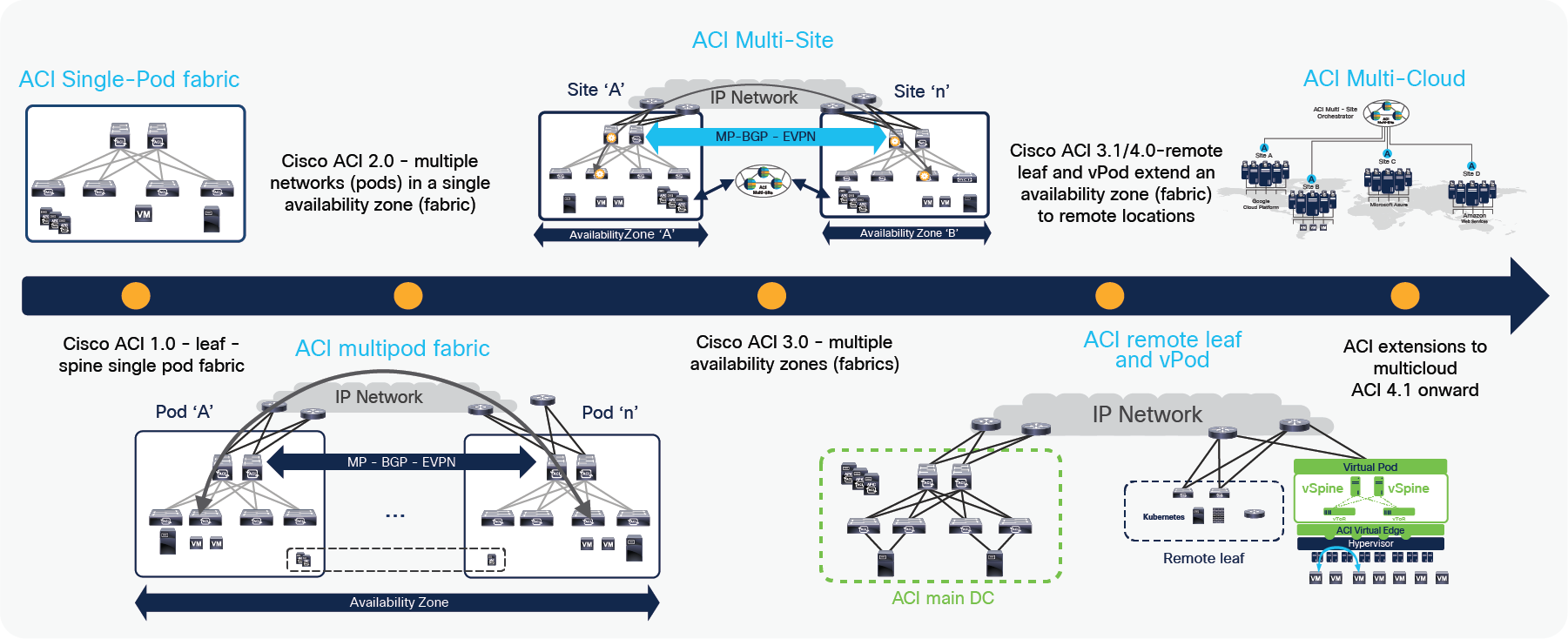
ACI fabric and policy domain evolution
Cisco ACI Release 1.0, consisted of a classic leaf-and-spine two-tier fabric (a single Pod) in which all the deployed leaf nodes are fully meshed with all the deployed spine nodes. A single instance of Cisco ACI control-plane protocols runs between all the network devices within the pod. The entire Pod is under the management of a single Cisco Application Policy Infrastructure Controller (APIC) cluster, which also represents the single point of policy definition.
Cisco ACI Release 2.0 introduced the Cisco ACI Multi-Pod architecture. This model calls for the deployment of separate Cisco ACI Pods, each running separate instances of control-plane protocols and interconnected through an external IP routed network (or interpod network [IPN]). The Cisco ACI Multi-Pod design offers full resiliency at the network level across pods, even if the deployment remains functionally a single fabric, with all the nodes deployed across the Pods under the control of the same APIC cluster. The main advantage of the Cisco ACI Multi-Pod design is hence operational simplicity, with separate Pods managed as if they were logically a single entity.
For more information about the Cisco ACI Multi-Pod design, refer to the following link:
https://www.cisco.com/c/en/us/solutions/collateral/data-center-virtualization/application-centric-infrastructure/white-paper-c11-737855.html.
The maximum latency supported between Pods is 50 msec RTT.
The need for complete isolation across separate Cisco ACI networks led to the Cisco ACI Multi-Site architecture, introduced in Cisco ACI Release 3.0. Cisco ACI Multi-Site offers connectivity between completely separate ACI fabrics (sites) that are managed by a Cisco Nexus® Dashboard Orchestrator (NDO) (formerly known as Cisco Multi-Site Orchestrator [MSO]). Each ACI fabric has an independent APIC cluster and control plane to provide complete fault isolation. BGP EVPN is used to exchange control plane information and VXLAN is used for data-plane communication between ACI Sites and to extend the policy domain by carrying to policy information in the VXLAN header. Cisco NDO provides centralized policy definition (intent) and management by providing the following functionalities:
● Monitoring the health-state of the different ACI sites.
● Provisioning of day-0 configuration to establish inter-site EVPN control plane.
● Defining and provisioning policies across sites (scope of changes).
● Inter-site troubleshooting.
● Disaster Recovery
● Multi-cloud connectivity
For more information about the Cisco ACI Multi-Site design, refer to the following link:
https://www.cisco.com/c/en/us/solutions/collateral/data-center-virtualization/application-centric-infrastructure/white-paper-c11-739609.html.
Cisco ACI policies can be extended to public clouds through integration with AWS (Cisco ACI Release 4.1) and Microsoft Azure (Cisco ACI Release 4.2). Using Cisco Nexus Dashboard Orchestrator (NDO), customers can deploy consistent policies across the on-premises data center and a public cloud. More details of the Cisco ACI public cloud integration are available at following links:
The need to extend connectivity and consistent policies to remote locations where it is not possible or desirable to deploy a full ACI Pod (with leaf and spine nodes) led to the development of the remote leaf solutions. With Cisco remote leaf solutions, the APIC controller deployed in the ACI main Datacenter (DC) manages the remote leaf switches connected over a generic IP Network (IPN). Remote location DCs may not be large in size, hence the remote leaf solution allows to deploy only Leaf switches, while the spines remain in the main ACI Datacenter. The APIC controller manages and operates the remote leaf nodes as if those were local leaf switches, pushing there all the centrally defined ACI policies. This architecture is the main focus of this document and will be discussed in great detail in the following sections.
Benefits of using the remote leaf solution
The remote leaf solution provides multiple benefits: with this solution an administrator can manage remote data centers without investing in APIC controllers and spine switches at remote locations.
The following list illustrates some key advantages of the remote leaf solution:
● Extension of the ACI policy model outside the main data center to remote sites distributed over an IP backbone.
● Extension of the ACI fabric to a small data center without investing in a full-blown ACI Fabric.
● Centralized policy management and control plane for remote locations.
● Small form factor solution at locations with space constraints.
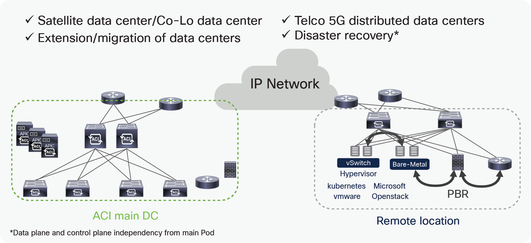
Remote leaf use cases
There are multiple use-cases of the remote leaf solution, the following list provides some examples:
● Satellite/Co-Lo Data CenterSatellite/Co-Lo Data Center
Due to business demands, enterprises or service providers often have a main Data Center (DC) and many small satellite DCs distributed across multiple locations. There is a demand for centralized management of all these DCs to simplify operations. There is also a need to ensure that satellite DCs have same networking, security, monitoring, telemetry, and troubleshooting policy as the main DC. ACI remote leaf provides the solution for these demands.
It is also possible to use remote leaf switches at a Co-Lo facility to manage and apply policies in the same way as in on prem DCs.
● Extension and Migration of DCsExtension and Migration of DCs
Remote leaf deployments simplify the provisioning of L2 and L3 multi-tenant connectivity between locations with a consistent policy. During the migration of DCs, there is a need to build DCI over which a workload can be migrated between DCs. The remote leaf solution allows the extension of a L2 domain from ACI main DC to remote DCs. An administrator can then migrate workloads using vMotion using L2 extension built through the remote leaf solution.
● Telco 5G distributed DCsTelco 5G distributed DCs
Typically Telecom operators build DCs at central and edge locations, but now due to increasing demands, and in order to provide better experience to subscribers, some services are moving to an aggregation layer. DCs are becoming smaller, but lot more in number, there is a demand to have centralized management and consistent policy for these DCs. The Cisco remote leaf solution allows the centralized management of these DCs by providing full day-0 and day-1 automation, consistent day-1 policy and end to end troubleshooting across any location.
● Disaster RecoveryDisaster Recovery
With remote leaf direct traffic forwarding and Pod redundancy enhancements, traffic forwarding from a remote leaf will continue to work even when a remote leaf loses connectivity to the spines of a logically connected DC. This solution works for smaller Disaster Recovery (DR) DCs where the full fabric can’t be deployed. Details about this are explained in this white paper in the section “Failure handling in remote leaf deployment.”
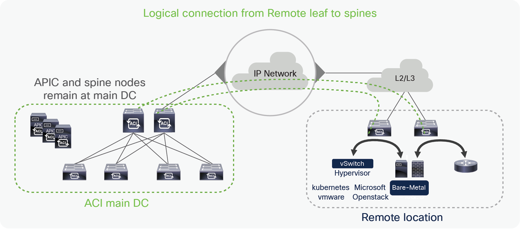
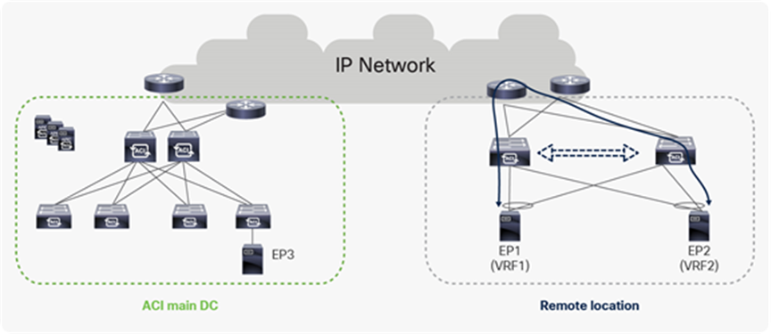
Remote leaf architecture overview
In the remote leaf solution, APIC controllers and spines are located at the main DC, while leaf switches at the remote location (remote leaf) and they logically connect to spines in the main DC over an IP network. Discovery, configuration and pushing policies to the remote leaf is done by the APIC cluster at the main DC. Remote leaves connect to the spines of one of the Pods in the Main DC over VXLAN tunnels.
Just like a local leaf, a remote leaf can be used to connect virtual servers, physical servers and containers. Traffic to the end points connected to a remote leaf is locally forwarded through remote leaves. Remote location firewalls, routers, load-balancers or other service devices can be connected to remote leaf switches in a similar way to the one that is used to connect them to local switches. Administrator can use ACI service graphs to perform service chaining for remote location DCs with the ACI remote leaf solution. Only unmanaged service graph mode is supported when connecting service nodes to remote leaf switches. L2 extension on remote leaf can be achieved using static EPGs. Administrator can also use a L3Out to connect routers or other networking nodes at remote locations using the remote leaf solution.
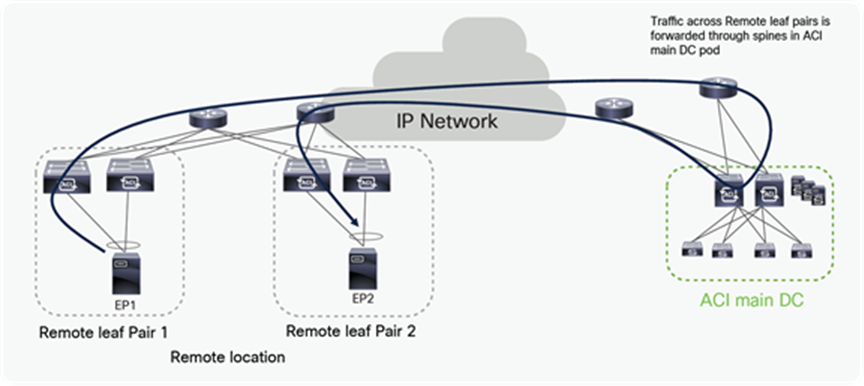
Starting from Cisco ACI Release 4.1(2), traffic from a remote leaf to any other remote leaf within the same Pod or across Pods is directly forwarded instead of being hair-pinned to the spines of the ACI main DC Pod to which the remote leaf nodes are associated (as shown in Figure 5 below).
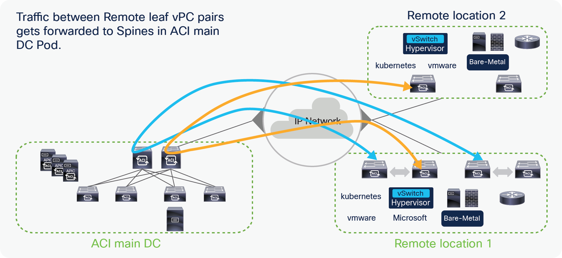
Traffic forwarding between remote leaf Pairs before Cisco ACI Release 4.1(2)
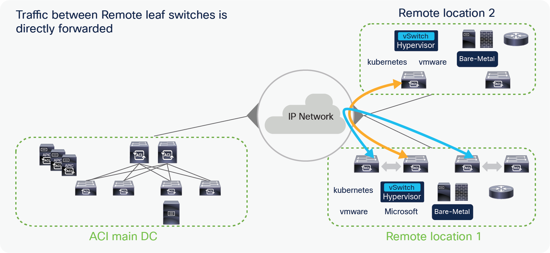
Traffic forwarding between remote leaf Pairs after Cisco ACI Release 4.1(2)
In the ACI Multi-Pod solution, remote leaf nodes get logically associated with one specific Pod. In the figure below, a remote leaf pair is associated with ACI Pod1.
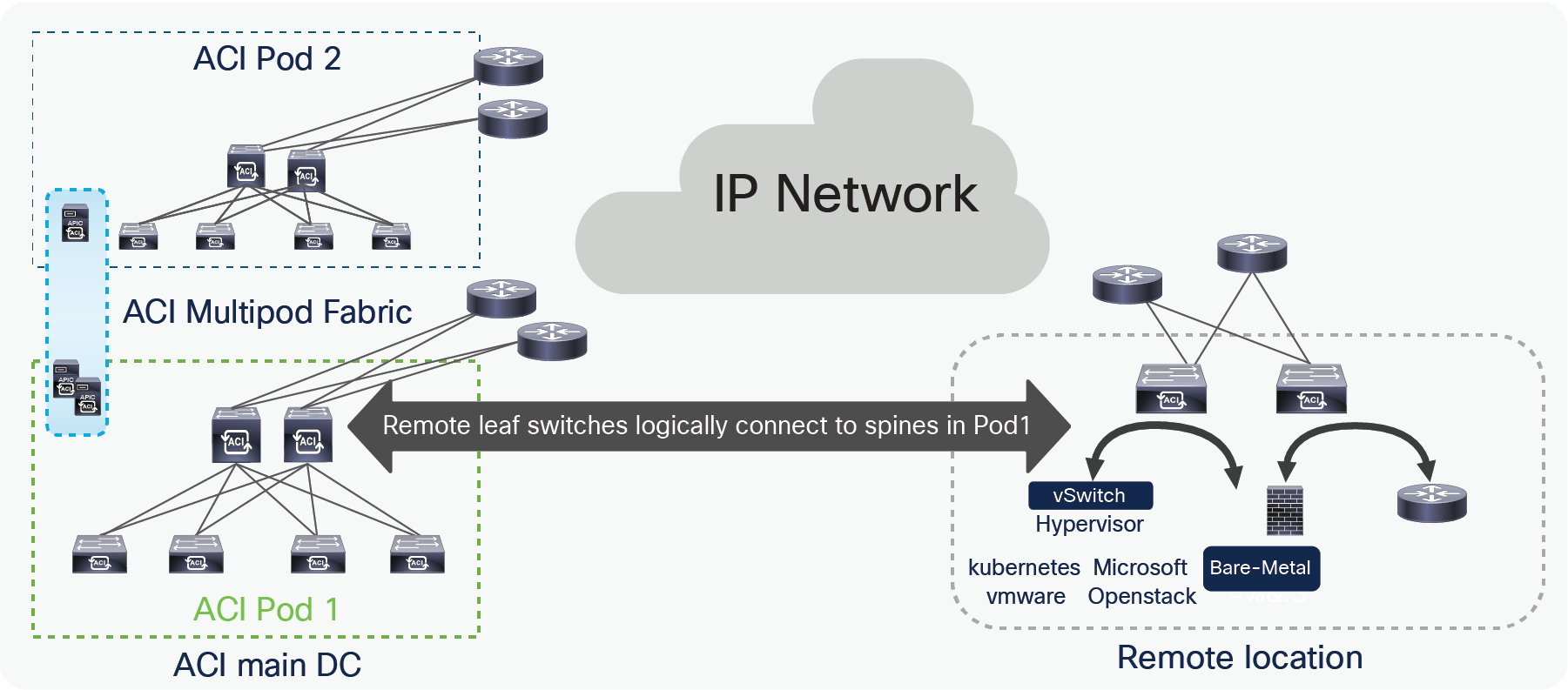
Logical connectivity of remote leaf to a spines of a Pod in a Multi-Pod fabric
The remote leaf solution is supported from the ACI 3.1(1) release. The remote leaf solution is supported with cloud scale ASICs such as C, EX, FX, FX2, FX3, GX switches onward. The following table has the list of hardware that supports remote leaf as of ACI release 5.2(3). Please check the latest release notes for the hardware support for a specific release.
| Leaf |
|
| Fixed spine:
● N9364C
● N9332C
● N9K-C9316D-GX
● N9K-C9364C-GX
● N9K-C93600CD-GX
● N9K-C9332D-GX2B
Modular spine with following Line cards:
● N9732C-EX
● N9736C-FX
● N9736Q-FX
● N9K-X9716D-GX
|
● N93180YC-EX
● N93180YC-FX
● N93108TC-EX
● N93108TC-FX
● N93180LC-EX
● N9348GC-FXP
● N9336C-FX2
● N93240YC-FX2
● N93360YC-FX2
● N93216TC-FX2
● N9K-C9358GY-FXP
● N9K-C93600CD-GX
● N9K-C9364C-GX
● Nexus C93180YC-FX3
● Nexus C93108TC-FX3P
● N9K-C9332D-GX2B
● N9K-C9316D-GX
● N9K-C93108TC-FX-24
● N9K-C93180YC-FX-24
● N9K-C93108TC-EX-24
● N9K-C93180YC-EX-24
● N9K-C9348GC-FX3
|
In cases when a deployment may already be using first generation spines that do not support remote leaf solution, first generation spines and next-gen spines can be part of the same ACI fabric. However, only next-gen spines should connect to the IPN to support remote leaf. The following diagram shows how to connect mixed generation spines within the fabric.
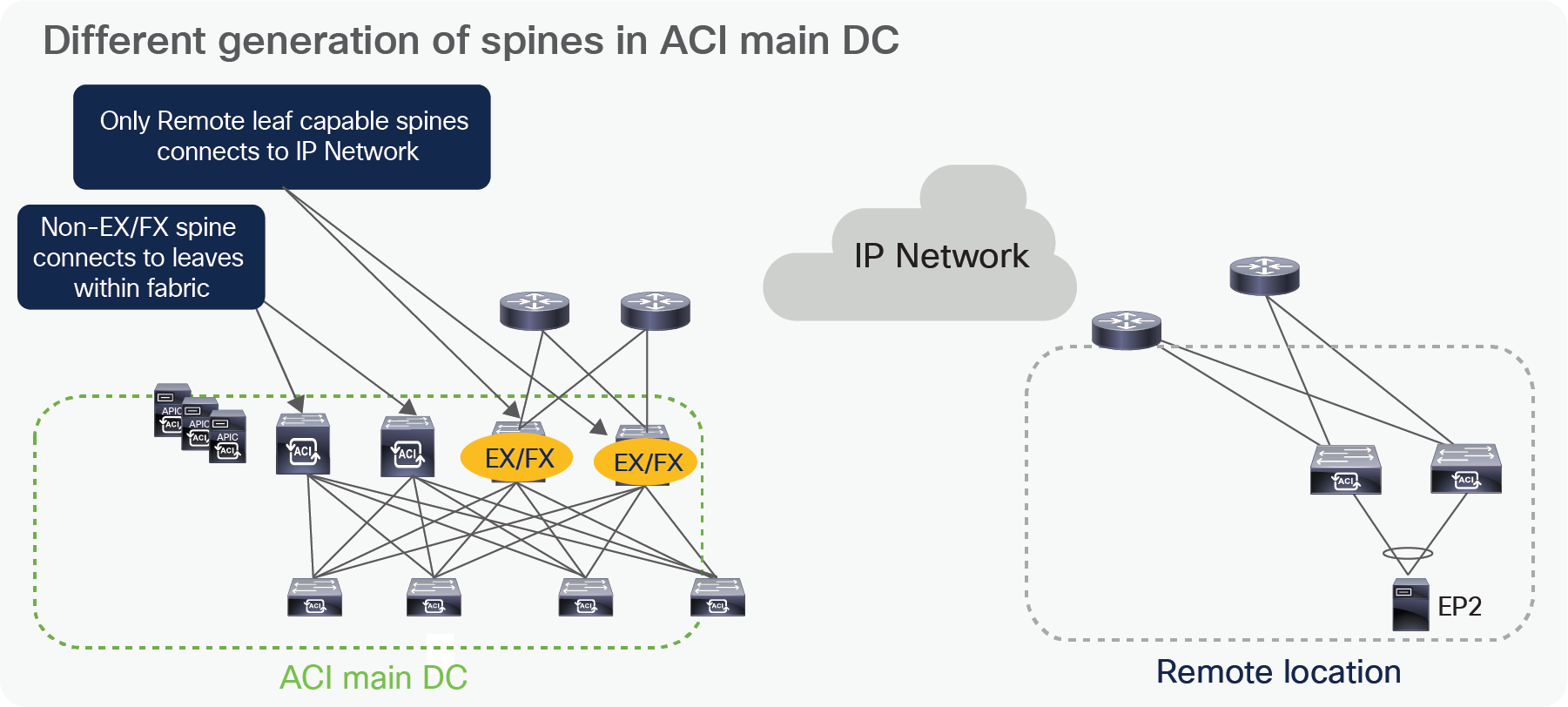
Different generation of spines in ACI main DC
IP Network (IPN) requirements for remote leaf
Remote leaves connect to the ACI main DC over an IP Network (IPN). Below is the list of requirements for the IPN:
● VXLAN is used as an overlay between the ACI main DC and a pair of remote leaves. To take care of the overhead of the VXLAN encapsulation, it’s important to increase at least 50B MTU in the IPN network to allow data-plane communication between endpoints in the main DC and at the remote location (this is valid assuming the endpoints source traffic of the default 1500B MTU size). Additionally, the MTU for control plane traffic between the spines in the main DC and the remote leaf nodes should also be tuned (by default it tries to use up to 9000B MTU). The following snapshot from the APIC controller highlights how to tune the MTU of control plane traffic to 1500 Bytes.
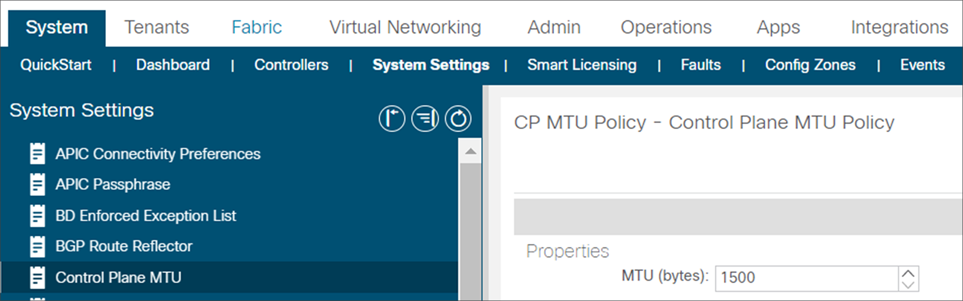
Definition of the Control Plane MTU
● The latency between the ACI main DC and the remote Leaf should be less than 300 msec Round Trip Time (RTT).
● A minimum of 100 Mbps bandwidth in the IP Network. Starting from Cisco ACI Release 4.2.4, the requirement has been lowered to 10 Mbps of bandwidth.
● The remote leaf solution requires the /32 Tunnel End Point (TEP) IP addresses of the remote leaf switches and main data center leaf/spine switches to be advertised across the main data center and remote leaf switches without summarization.
● Dedicated links between the RL nodes and the Uplink routers must be deployed for supporting RL discovery and VXLAN traffic destined to other RL nodes or the main fabric. This means that separate links must instead be configured as part of local L3Out(s) to provide connectivity toward the external network domain (that is, shared links are not supported for those different connectivity requirements).
The remote leaf solution has specific IP addressing requirements related to the ACI main DC APICs, spines and Border Leaf IP addresses for these components to be reachable by the remote leaf. These requirements have changed from cisco ACI Release 4.1(2). The following section explains this topic.
Reachability requirements from remote leaf to ACI main DC before Cisco ACI Release 4.1(2)
A remote leaf pair is logically associated to one of the Pods of the ACI main DC. Remote leaf nodes should have reachability to the VTEP pool of its logically associated Pod. This could be achieved via the backbone if the TEP pool is enterprise routable. If the TEP pool used by the main ACI DC is a private address space that cannot be routed over the IPN, you can use a dedicated VRF on the IPN or a tunnel from the RL to the main ACI DC.
Reachability requirements from remote leaf to ACI main DC from Cisco ACI Release 4.1(2)
In order to solve the challenge of advertising the ACI Pod TEP pool to remote locations, Cisco ACI Release 4.1(2) added the support for an external TEP subnet for the Pod, to be used in addition to the Pod pool subnet which has been used to provision the ACI Pod. This solution allows you to advertise only the external subnet TEP IP addresses to remote locations from the ACI main DC. By doing this all communication from remote leafs to the ACI main DC happens using the external subnet IP addresses assigned to spines, APIC controllers, and Border Leaves.
With this solution ACI automatically assigns IP addresses to APIC controllers, spines, and border leaves from the external subnet in addition to the private addresses, a Pod pool that was assigned from a private address space is not required to be advertised outside of the ACI main DCs, administrators can configure an additional external subnet later when they need to add more ACI leaves, spines, or APIC controllers, instead of providing a larger external subnet pool on day 0.
The minimum supported subnet range for an external subnet is /27. Also, there is no requirement for the various external TEP pools to be adjacent.
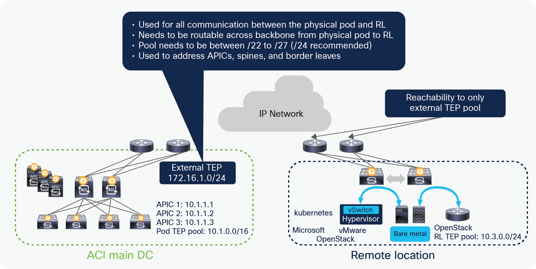
External TEP reachability between RL and the ACI main DC
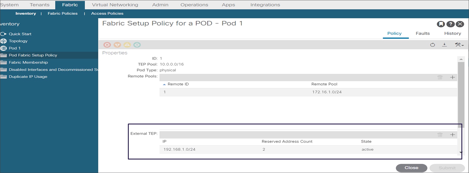
External TEP subnet configuration
Please note that the External subnet configuration is mandatory for supporting the establishment of direct communication between remote leaf pairs and for deploying remote leaf nodes with ACI Multi-Site. It is mandatory to deploy the external TEP configuration for any new deployment.
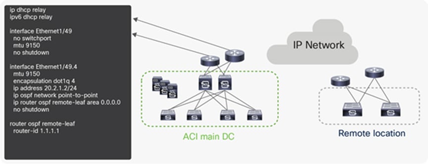
● The following configuration is needed on the upstream router connected to a remote leaf:
● OSPF with VLAN-4 sub-interface at the upstream router connected to the remote leaf.
DHCP relay to the APIC controller’s IP address. If the external TEP is configured on the APIC, you should use the routable IP address of the APIC as the DHCP relay IP address.
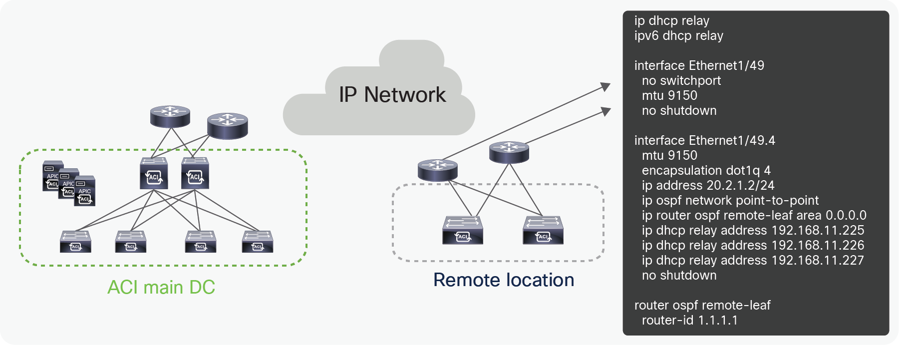
Configuration for the upstream router connected to remote leaf with a private VTEP pool
The following figure shows how to check the routable IP address of the APIC. The upstream router connected to RL needs to have a DHCP relay to the routable IP address of the APIC.
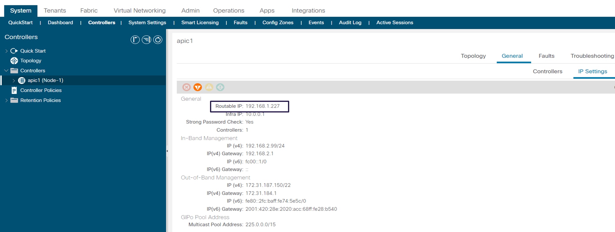
Routable IP address of the APIC
Configuration of the upstream router connected to a remote leaf with an External TEP pool
The following configuration is needed on the upstream router connected to the ACI spine.
● OSPF with VLAN-4 sub-interface at the upstream router connected to the spines. Please note that starting from Cisco ACI Release 4.1(2), there is no need any more to deploy a separate VLAN-5 sub-interface for integrating RL nodes with Multi-Pod.
● If you do not use vlan-5 with Multi-Pod and remote leaf, you must configure remote leaf Direct Traffic Forwarding. Remote leaf direct forwarding is the default and only choice starting from ACI 5.0.
The following diagram provides the example configuration for upstream routers connected to spines.
Configuration for upstream routers connected to the ACI spines
Remote Leaf Uplink to IPN connectivity enhancement with in APIC release 6.1(1)
IPN L3out and User Tenant L3out connectivity over sub-interfaces
Recommended QOS configuration for remote leaf
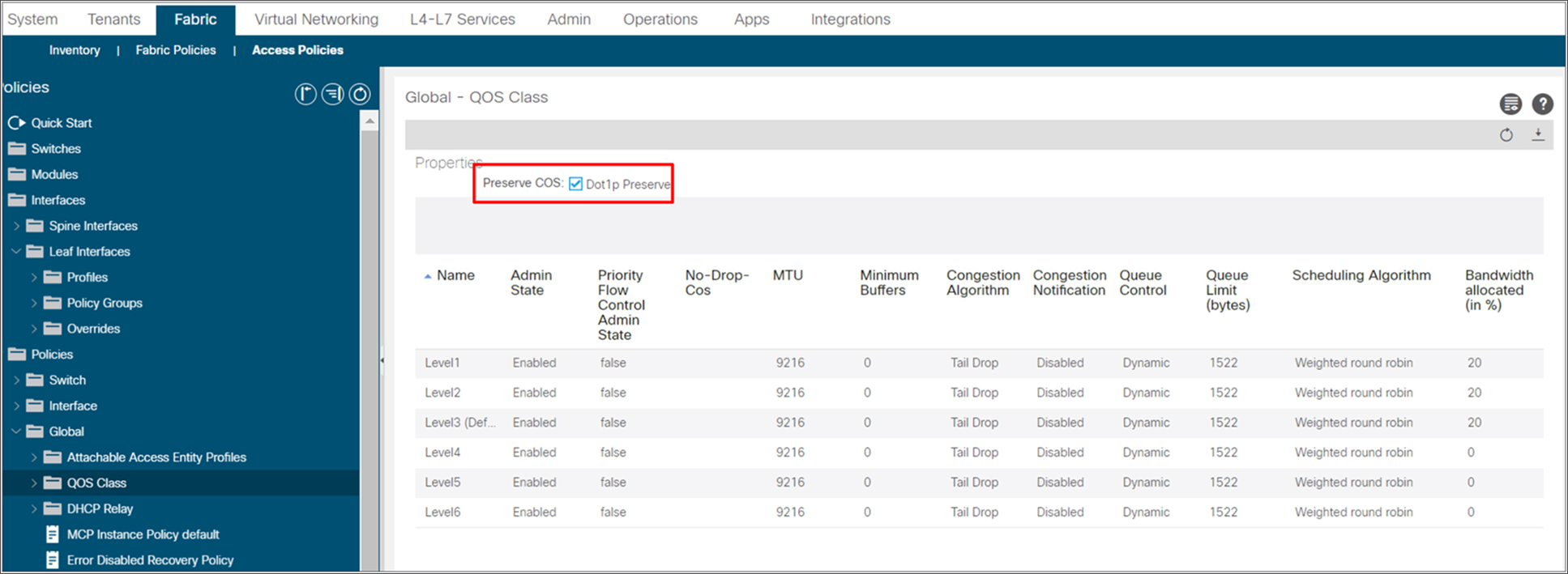
There may be a requirement to preserve the COS values coming from remote endpoints connected to EPGs and carry the same value to the ACI main DC Pod. To achieve this goal, it is possible to enable the preservation of the COS value (“Dot1p Preserve” flag) as part of the “External Access Policies” on APIC, as shown in the snapshot below. With this configuration, the COS value of the original frame received from the endpoint connected to the remote leaf node is translated to a corresponding DSCP value that is then copied to outer IP header of the VXLAN encapsulated frame. This value can then be propagated across the IPN and converted back to the original COS value before sending the traffic to the endpoints connected in the main ACI DC (and vice versa).
Configuration for enabling COS preservation
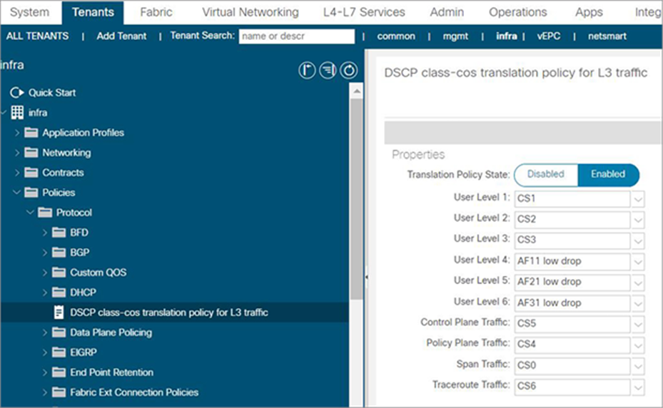
Another common requirement is to classify ACI QOS levels and default classes to a DSCP value within IPN, so that the user can prioritize traffic based on DSCP. To achieve this requirement, ACI Fabric should be enabled with “DSCP class-cos translation policy for L3 traffic.” The following snapshot from the APIC controller shows how to map ACI QOS levels and default classes to DSCP values in IPN. The traffic between RL and spine in IPN is marked with DSCP based on the following mapping.
Configuration for enabling DSCP class-cos translation policy for L3 traffic
The following list provides some key points to remember while configuring QOS in ACI fabric for remote leaf:
● ACI Fabric expects that the DSCP values of the packet exiting from remote leaf and entering the spine and vice versa are the same, therefore the DSCP values of the packets cannot be modified inside the IPN.
● Dot1P preserve and DSCP translation policies cannot be enabled together.
● The following table explains the COS values that are used within ACI Fabric for the default QOS classes and recommended actions for these QOS classes in IPN.
Table 1. Recommended QOS configuration in IPN
|
|
COS value within fabric |
Recommendation |
| Control plane |
COS5 |
Prioritize in IPN |
| Policy plane |
COS3 |
Prioritize in IPN |
| Traceroute |
COS6 |
Prioritize in IPN |
| SPAN |
COS4 |
De-prioritize in IPN |
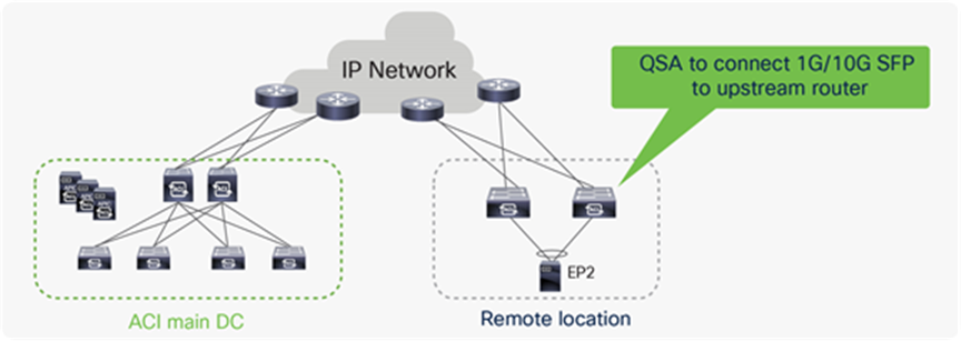
1G or 10G connectivity from remote leaf switches to upstream Router
Upstream Routers at remote locations may not have 40G/100G connectivity, hence it might be required to connect remote leaf switches with upstream routers with 1G or 10G connectivity. Remote leaf switches with QSA adapter can be connected with 1G or 10G connectivity. Please check the latest optics compatibility matrix for QSA support.
Options for connecting 1G or 10G links from a remote leaf to an upstream router
A remote leaf gets discovered and configured automatically as soon as it gets powered up at a remote location. The APIC controller at the ACI main DC Pod and the IPN need to be pre-configured for this to happen. For a complete discovery of a remote leaf, the following two key steps takes place:
● The IP address allocation to the uplink interfaces, and the configuration push to the remote leaf.
● The TEP IP address assignment to the remote leaf.
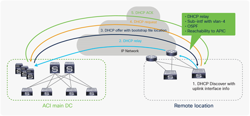
IP address assignment for the remote leaf uplink, and configuration push to the remote leaf
The following list describes the exact steps for the remote leaf provisioning:
● When a remote leaf gets powered on, it sends a broadcast DHCP discover message out of its uplink interfaces.
● The upstream router’s interfaces towards the remote leaf are configured to relay DHCP discover to APIC controller so when the DHCP discover message is received by the upstream router, it relays the DHCP discover message to the APIC controller(s).
● The APIC controllers send a DHCP offer for the uplink interface of remote leaf along with the bootstrap configuration file location in the DHCP offer message.
● The remote leaf picks up one of the APIC controllers and sends a DHCP request for the uplink interface of the remote leaf to the APIC controller.
● The APIC controller sends a DHCP ACK to complete the IP address allocation for the uplink IP address.
● This process gets repeated for all the uplink addresses. To get a bootstrap configuration file from the APIC controller, the remote leaf automatically configures a static route with the upstream router as the next-hop.
● After receiving the configuration file, this static route is removed and remote leaf is configured as per the configuration file.
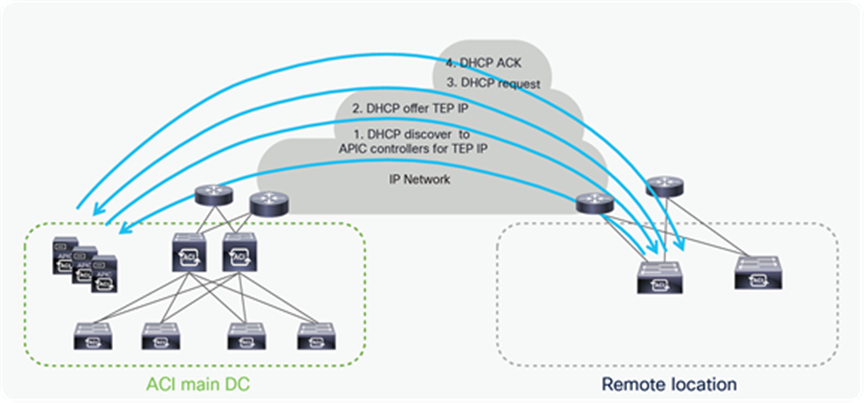
● The next step in the remote leaf discovery is the assignment of a TEP address to the remote leaf switches
● The remote leaf gets full IP connectivity to the APIC controllers once its uplinks get an IP address, it sends a DHCP discover message to APICs to receive the TEP address.
● APIC controllers sends the DHCP offer for a TEP IP address.
● The remote leaf picks up one of the APIC controllers and sends the DHCP request for the TEP IP.
● The APIC controller sends a DHCP ack to complete the DHCP discovery process for the TEP IP address.
● Once this process is over, the remote leaf becomes active into the Fabric and it’s shown in topology diagram at the APIC controller.
The following diagram illustrates the assignment of TEP addresses to remote leaves.
TEP address assignment to remote leaf
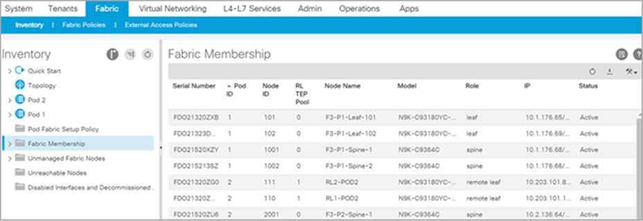
Fabric membership table after successful discovery of remote leaf
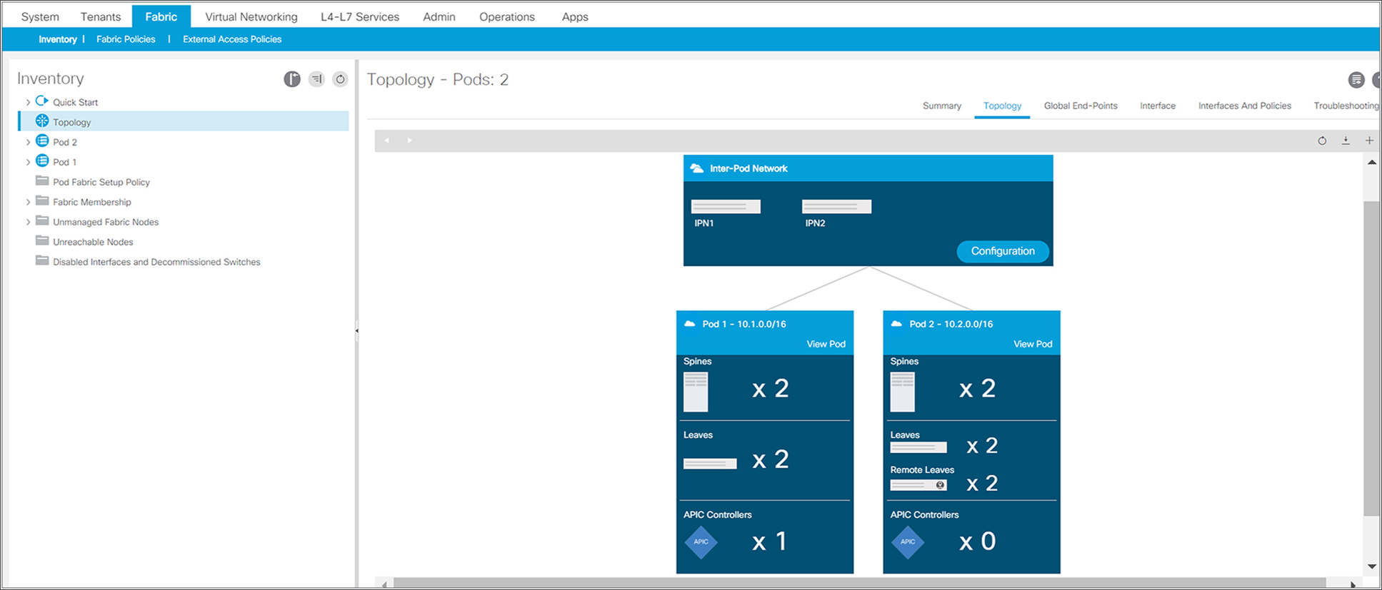
Remote leaf switches can be connected to ACI Multi-Pod Fabric. The following snapshot from the APIC controller shows the ACI Fabric with two Pods. The remote leaf switches are part of Pod2.
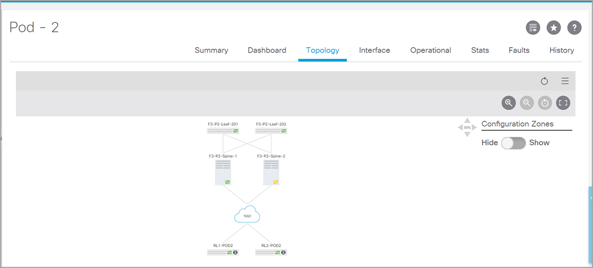
Overall fabric topology with Multi-Pod and remote leaf
Topology diagram of a Pod with remote leaf
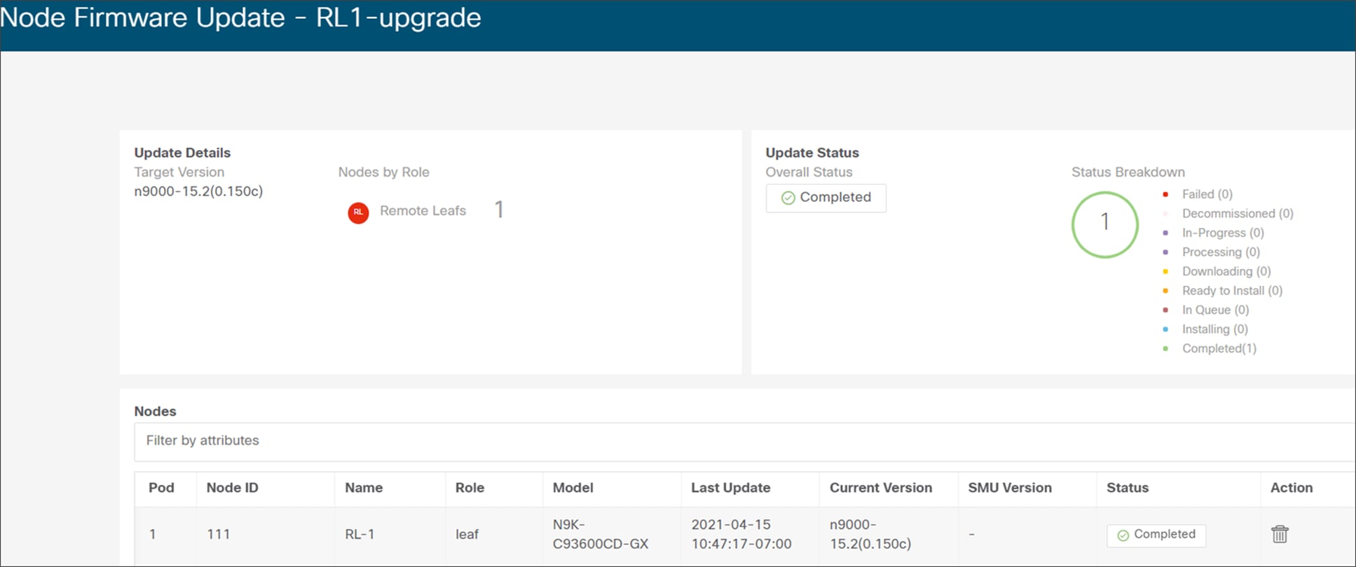
Remote leaf switches can be upgraded in the same way as local leaves using APIC controllers. Administrators can divide the switches into odd and even groups and upgrade one group at a time.
The following picture is the snapshot from an APIC controller GUI that shows remote leaf switches divided into groups (odd and even) for upgrades.
Snapshot from APIC for firmware upgrade of a remote leaf
ACI connectivity and policy extension to remote leaf
One of the main use-case of remote leaf is to provide centralized management and consistent ACI Policy to remote locations DC. Administrators can define ACI networking policies such as Tenant, VRF, BD, EPG, L3Outs, security policies such as contracts and micro-segmentation, telemetry policies, monitoring policies, troubleshooting policies for the main DC on the APIC controller and extend the same policy to Remote DC using remote leaf.
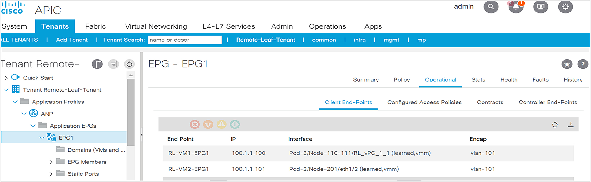
Remote leaf and local leaf have the same ACI features and functionalities. Single EPGs can have EPs located in local leaf as well as remote leaf. This functionality seamlessly offers L2 extension between the ACI main DC and remote locations without much complexity and extra protocol overheads.
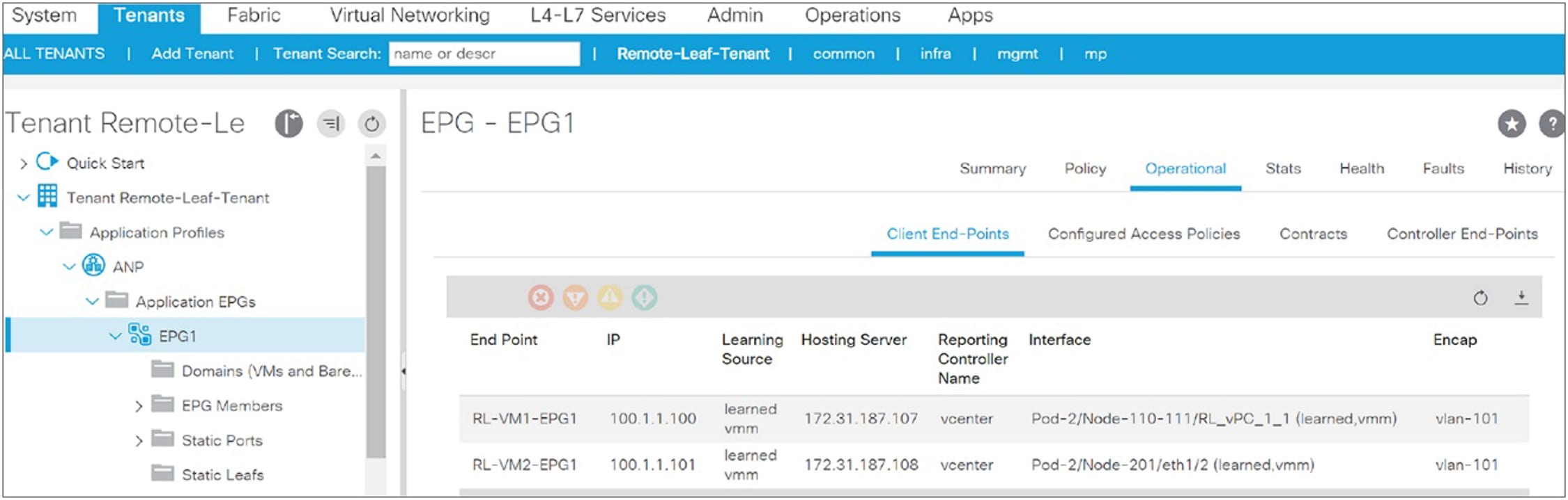
The following snapshot from the APIC controller shows that EPG1 is stretched to a remote leaf. It has end points connected to a remote leaf pair (Node-110 and Node-111) and to a local leaf (Node-201).
Snapshot from APIC for an EPG with endpoints connected to both local and remote leaf
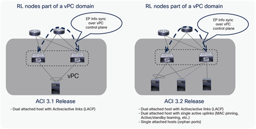
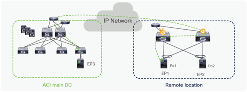
Endpoints can be connected to remote leaf switches in different ways, however remote leaf switches should always be configured as part of vPC domain. The following options are possible (also shown in the diagram below):
● End points connected to remote leaf switches using a vPC port-channel (usually leveraging LACP).
● Endpoints are single home connected to one of the remote leaf switch as ‘orphan port(s)’.
● Endpoints are dual home connected to remote leaf switches leveraging any form of active/standby NIC redundancy functionality (MAC pinning, NIC teaming, etc.).
Notice that options 2 and 3 are only supported starting from the ACI 3.2 release.
Options to connect endpoints to remote leaf
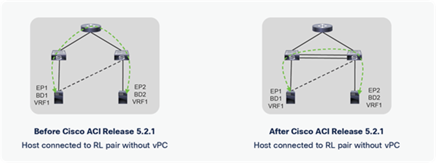
Starting from Cisco ACI Release 5.2.1, two remote leaf switches that are part of the vPC domain can be connected back to back using fabric uplinks. This allows the host connected using orphan ports to prefer back-to-back connected links over upstream router links. This feature is useful if the user wants to save bandwidth on the upstream router, and it keeps all traffic local to the remote leaf.
RL back-to-back connection topology
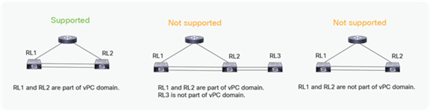
Please note that RL back-to-back links are supported only for RLs that are part of a vPC domain, as shown in the figure below.
RL back-to-back supported topologies
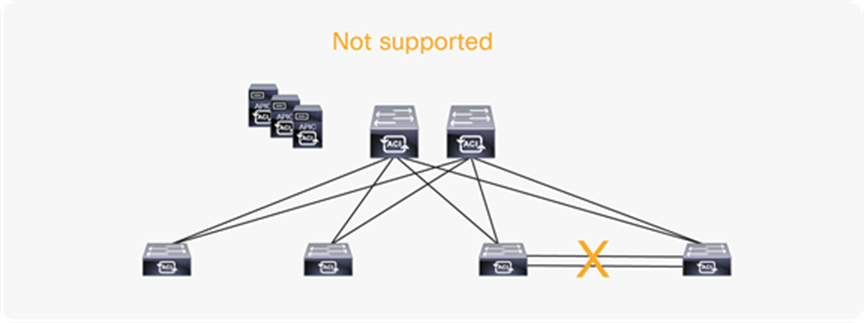
Back-to-back links are not supported for regular ACI leafs. A fault is raised for mis-cabling if non-RLs are connected with a back-to-back link.
Back-to-back connection in ACI main Pod
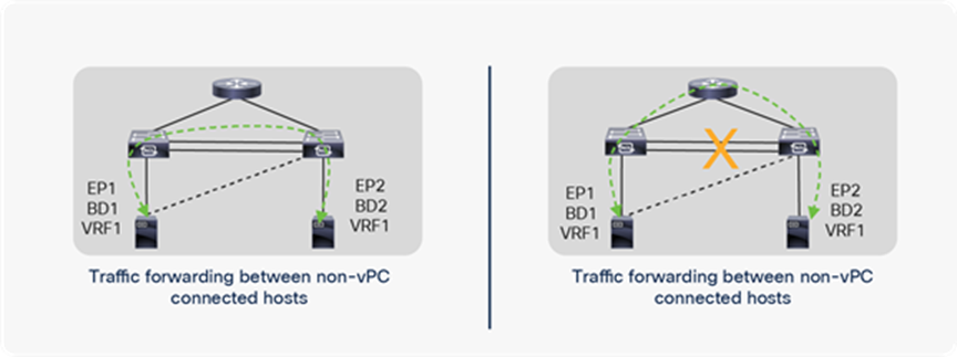
Please note that a back-to-back link is preferred for communication between remote leaf switches, but if that link goes down, the communication can happen through an uplink connected to an upstream router, as shown in the below figure.
RL back-to-back failure
Similarly, if a RL loses all of its uplinks toward the IPN router, it can use a back-to-back link and connect to all other Pods and RLs through back-to-back links, as shown in Figure 22.
All uplink failure with RL back-to-back connection
Remote leaf Control Plane and data plane
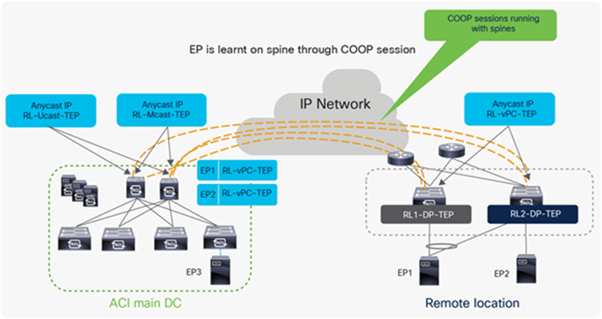
In a Cisco ACI fabric, information about all the endpoints connected to leaf nodes is stored in the COOP database available in the spine nodes. Every time an endpoint is discovered as locally connected to a given leaf node, the leaf node originates a COOP control-plane message to communicate the endpoint information (IPv4/IPv6 and MAC addresses) to the spine nodes. COOP is also used by the spines to synchronize this information between them.
In a Cisco ACI remote leaf deployment as well, host information for discovered endpoints must be exchanged with spine nodes. The remote leaf builds a COOP session with the spines and updates the spine with the information of locally attached host.
There are specific TEP IP addresses that are defined on spines and remote leaves to exchange control plane and data plane information.
RL-DP-TEP (Remote leaf Data-Plane Tunnel End Point) - This is a unique IP address automatically assigned to each remote leaf switch from the TEP pool that is allocated to the remote location. VXLAN packets from a remote leaf node are originated using this TEP as the source IP address when the endpoints are connected without vPC.
RL-vPC-TEP (Remote leaf vPC Tunnel End Point) – This is the anycast IP address automatically assigned to the vPC pair of remote leaf nodes from the TEP pool that is allocated to the remote location. VXLAN packets sourced from remote leaf switches are originated using this TEP as the source IP address when endpoints are connected using vPC.
RL-Ucast-TEP (Remote leaf Unicast Tunnel End Point) – This is the anycast IP address automatically assigned to all the spines to which the remote leaf switches are being associated. It is automatically assigned from the external TEP pool if configured; otherwise, it is assigned from the ACI Pod TEP pool. When unicast packets are sent from endpoints connected to the RL nodes to an endpoint connected to the ACI main Pod local leaf, VXLAN encapsulated packets from RL are sent, with the RL-Ucast-TEP address as the destination and RL-DP-TEP or RL-vPC-TEP as the source. Any spine in the ACI main DC Pod can then receive the traffic, de-encapsulate it, perform the required L2 or L3 lookup, and finally re-encapsulate it and forward it to a leaf in the local Pod.
RL-Mcast-TEP (Remote leaf Multicast Tunnel End Point) – This is another anycast IP address assigned to all the spines to which the remote leaf switches are being associated. It is automatically assigned from the external TEP pool if configured; otherwise, it is assigned from the ACI Pod TEP pool. When BUM (Layer 2 Broadcast, Unknown Unicast or Multicast) traffic is generated by an endpoint connected to the remote leaf nodes, it gets VXLAN-encapsulated by the RL node and sent with the RL-Mcast-TEP address as the destination and RL-DP-TEP or RL-vPC-TEP as the source. Any of the spines in the ACI Pod can receive BUM traffic and forwards it inside the fabric.
The following diagram shows the EP learning process on the spines through COOP. It also shows the TEP addresses present on remote leaves and spines.
TEP addresses on spine and remote leaf
Let’s understand how ACI forwards traffic under different scenarios for a single Pod with remote leaf:
● Unicast Traffic between endpoints dual-homed to a pair of remote leaf nodes
● Unicast traffic between endpoints single-homed to a pair of remote leaf nodes (orphan ports)
● Broadcast, Unknown Unicast and Multicast (BUM) traffic generated by an endpoint connected to a pair of remote leaf nodes and sent to a Local leaf (in the ACI Pod) when BD is configured in flood mode
● Broadcast, Unknown Unicast and Multicast (BUM) traffic generated by an endpoint connected to a pair of remote leaf nodes and sent to a Local leaf when BD has the default proxy mode configuration
● Unicast traffic from an endpoint connected to a Local leaf to an endpoint connected to the remote leaf nodes
● Unicast traffic from an endpoint connected to the remote leaf to an endpoint connected to a Local leaf
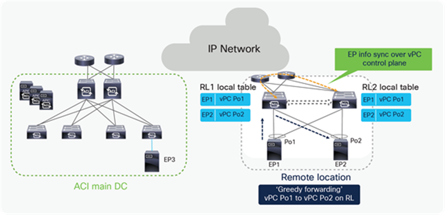
Unicast traffic between remote leaf Nodes (Dual-Homed Endpoints)
It’s always recommended to configure remote leaf switches as part of a vPC domain even if the endpoints are single homed. When remote leaves are configured as a vPC pair, they will establish a vPC control plane session between them over the upstream router. Endpoint information in the same EPG is synchronized over the vPC control plane session.
Communication between dual-homed endpoints is usually handled locally on the RL node receiving the traffic from the source endpoint, a behavior named “Greedy Forwarding” and highlighted in the figure below.
Unicast RL to RL packet flow when end point is connected to RL with vPC
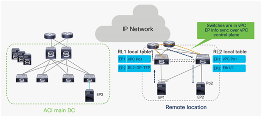
Unicast traffic between remote leaves with Orphan port
Communication between endpoints single attached to remote leaf nodes (orphan ports) is supported from the ACI 3.2 release. EP information is synced between the remote leaf switches over the vPC control plane session. In the following diagram EP1 and EP2 are part of same EPG. Since the EPG is deployed on both the RL nodes, they synchronize EP1 and EP2 information over the vPC control plane and traffic between the single-homed endpoints is forwarded establishing a VXLAN tunnel through the upstream router.
Unicast RL to RL packet flow when the endpoint is connected to RL as an orphan port
Broadcast, Unknown Unicast and Multicast (BUM) traffic from remote leaf to Local leaf when BD in flood mode
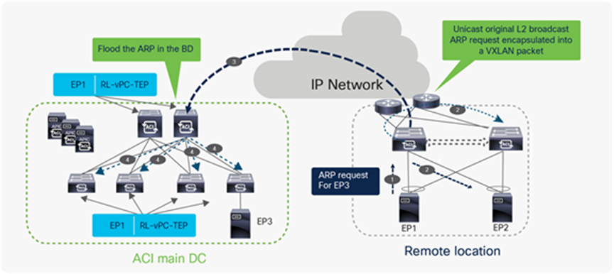
Broadcast, Unknown Unicast and Multicast traffic (BUM) traffic flow from RL to ACI main DC when bridge domain is in flood mode
The ACI remote leaf solution does Head End Point Replication (HREP) for Broadcast, Unknown and Multicast (BUM) traffic when BD is configured in flood mode. In the above example, the endpoint (EP1) connected to the remote leaf nodes sends an ARP request for the endpoint connected to local leaf (EP3), and the ARP request is first flooded within the remote leaf pair. Remote leaf learns about the EP1 and send a COOP update to the spine about EP1’s location; with this COOP update, spine learns that EP1 is attached to RL.
The remote leaf that gets the ARP packet from the host also encapsulates the ARP packet in the VXLAN header and forwards a single packet to the spines with the destination TEP address in the VXLAN header as the anycast address of the spine (RL-Mcast-TEP). The remote leaf uses the source TEP address in the VXLAN header as the anycast address of the RL vPC pair (RL-vPC-TEP), since EP1 is connected to RL using vPC.
The spine floods the packet to all the leaves using the BD multicast address. Every configured BD has a unique multicast address assigned inside the ACI Pod. When the spine floods the ARP packet with BD multicast IP addresses, the ARP packet will reach only the leaves that have endpoints actively connected to this BD. Leaf switches in the ACI main DC make an entry for EP1 with next-hop as RL-vPC-TEP and flood the ARP request to all interfaces that are part of the BD.
The above process ensures that the following ARP request generated by EP1 and received by the spines can then be directly forwarded to the leaf where the EP3 is connected, allowing the completion of the ARP exchange between EP1 and EP3.
Broadcast, Unknown Unicast and Multicast (BUM) traffic from remote leaf to Local leaf when BD in proxy mode
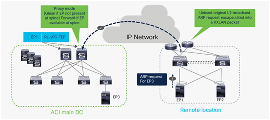
Broadcast, Unknown Unicast and Multicast traffic (BUM) traffic flow from RL to ACI main DC when bridge domain is in proxy mode
In the above example, the EP1 connected to remote leaf switches sends the ARP request for the EP3 that is connected to Local leaf. EP1 and EP3 are part of same BD, BD is in proxy mode, and ARP flooding is disabled. On receiving the ARP request, the remote leaf learns about the EP1 and sends a COOP update to the spine about the EP1 location; with this COOP update, the spine thus learns that EP1 is attached to RL. The remote leaf forwards the packet to the spine switches with RL-vPC-TEP as the source TEP address and RL-Ucast-TEP as the destination TEP address.
The spine forwards the ARP request to the destination leaf if it has information about EP3 in its database; otherwise, it sends a glean message to all of the leaves (including other remote leaf nodes associated to the same ACI Fabric). The glean message triggers each leaf to send an ARP request on all of the local interfaces in the BD that received the ARP request.
The process described above ensures that the following ARP request generated by EP1 and received by the spines can then be directly forwarded to the leaf where EP3 is connected, allowing the completion of the ARP exchange between EP1 and EP3.
Unicast traffic from local leaf to remote leaf
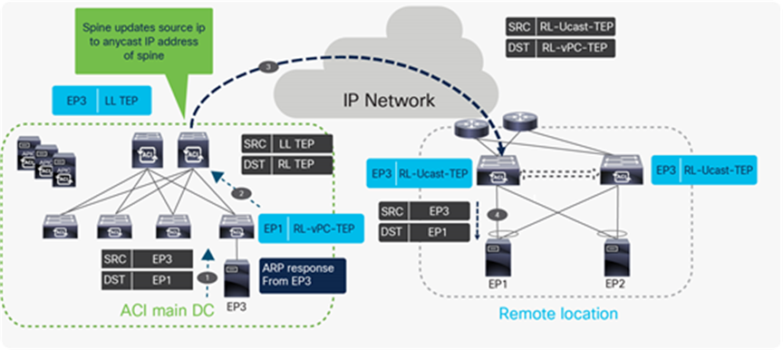
Unicast traffic flow from ACI main DC to RL
In the above example EP3 respond to ARP request sent from EP1. The following list is the sequence of events when the ARP response packet is forwarded to EP1 from EP3.
● EP3 sends a unicast ARP response to EP1 with sender MAC as EP3 and target MAC as EP1.
● The local leaf in the main DC receives the ARP response packet and it looks for the EP1 MAC address in its hardware table. It finds EP1 with next-hop of RL-vPC-TEP. It encapsulates ARP response packet in the VXLAN header with local leaf TEP (LL TEP) as the source TEP address and RL-vPC-TEP as the destination TEP. As previously explained, the destination TEP would be RL-DP-TEP if the remote leaf nodes were not configured as part of a vPC domain.
● When the spine receives the packet with RL-vPC-TEP as the destination TEP, it will update the source TEP as the anycast IP address of the spines (RL-Ucast-TEP)it will update the source TEP as the anycast IP address of the spines (RL-Ucast-TEP) and forwards the packet to the RL.
● One of the RL receives the packet, de-encapsulates the VXLAN header and forwards the ARP response to the locally attached host. The RL learns EP3 with next-hop of the anycast IP address of the spine (RL-Ucast-TEP).
Unicast traffic from remote leaf to local leaf
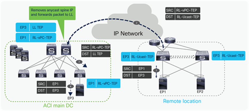
Unicast traffic flow from RL to ACI main DC
In the above example EP1 is sending a unicast packet to EP3. Following sequence of events happens when the packet is sent to EP3 from EP1.
● EP1 sends a unicast packet to EP3 with source IP as local IP EP1 and destination as EP3 (same applies to the MAC addresses). EP1 picks one of the links towards remote leaf for forwarding the packet based on hash.
● The packet from EP1 is received on one of the remote leaves. The receiving remote leaf does a Layer 2 look-up for EP3’s MAC. It finds the next-hop for EP3’s MAC as the anycast IP address of spine (RL-Ucast-TEP). The remote leaf encapsulates the packet into a VXLAN header with source TEP as RL-vPC-TEP and destination TEP as RL-Ucast-TEP.
● One of the spines receives this packet. The spine does a look up for the inner header destination (EP3’s MAC). It updates the destination TEP as the local leaf TEP (TEP) and forwards the packet to the leaf connected to EP3.
● The local leaf forwards the packet to the connected End point (EP3).
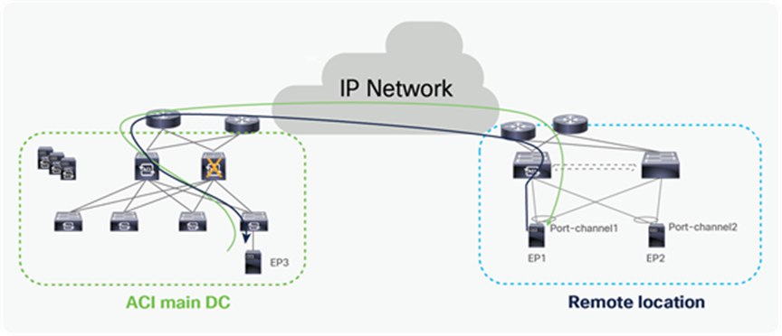
Traffic forwarding between remote leaf pairs before Cisco ACI 4.1(2)
The behavior shown in the figure below is applicable only to deployments running a code before Cisco ACI Release 4.1(2) or when “remote leaf direct traffic forwarding” is not enabled. Before Release 4.1(2), traffic between the remote leaf pair was forwarded through the spines in the ACI main DC Pod as shown in the figure below.
Traffic flow between remote leaf pairs before Cisco ACI Release 4.1(2) without the “remote leaf direct” feature
The following diagram and steps explain this behavior.
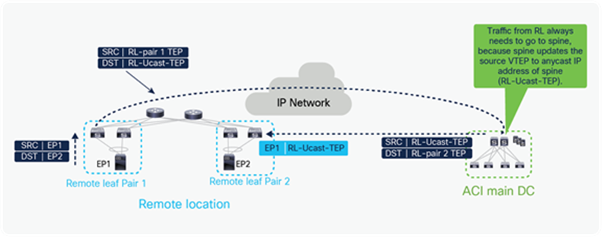
Endpoint learning between remote leaf pairs before Cisco ACI 4.1(2) without the “remote leaf direct” feature
In Figure 26, EP1 connected to remote leaf Pair 1 sends unicast traffic to EP2 connected to remote leaf Pair 2.
● When one of the remote leaf pair 1 nodes receives this packet, assuming it does not have any information about EP2’s MAC in its hardware table, it forwards the packet to the spine. When doing so, the remote leaf encapsulates the packet into a VXLAN header with source TEP as RL Pair 1 TEP and destination as the anycast IP address of the spine (RL-Ucast-TEP).
● This packet can be received by any spine of the main DC. The spine in the Main DC looks up the MAC address of EP2, and assuming it knows where it is located, it then forwards the packet to EP2 at remote leaf Pair 2. When doing so, and this is the critical point to understand, it changes the source TEP to RL-Ucast-TEP and destination to RL-Pair 2 TEPit changes the source TEP to RL-Ucast-TEP and destination to RL-Pair 2 TEP.
● As a consequence, the remote leaf Pair 2 will associate EP1’s MAC to the anycast IP address of the spine (RL-Ucast-TEP). Hence remote leaf Pair 2 will always send packets to spine in the ACI main DC before sending it to remote leaf Pair 1.
This forwarding behavior changes from Cisco ACI 4.1(2) if the customer enables “remote leaf direct traffic forwarding,” as explained in the following section.
Remote Leaf to Remote Leaf direct traffic forwarding from Cisco ACI 4.1(2)
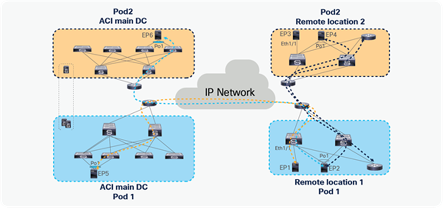
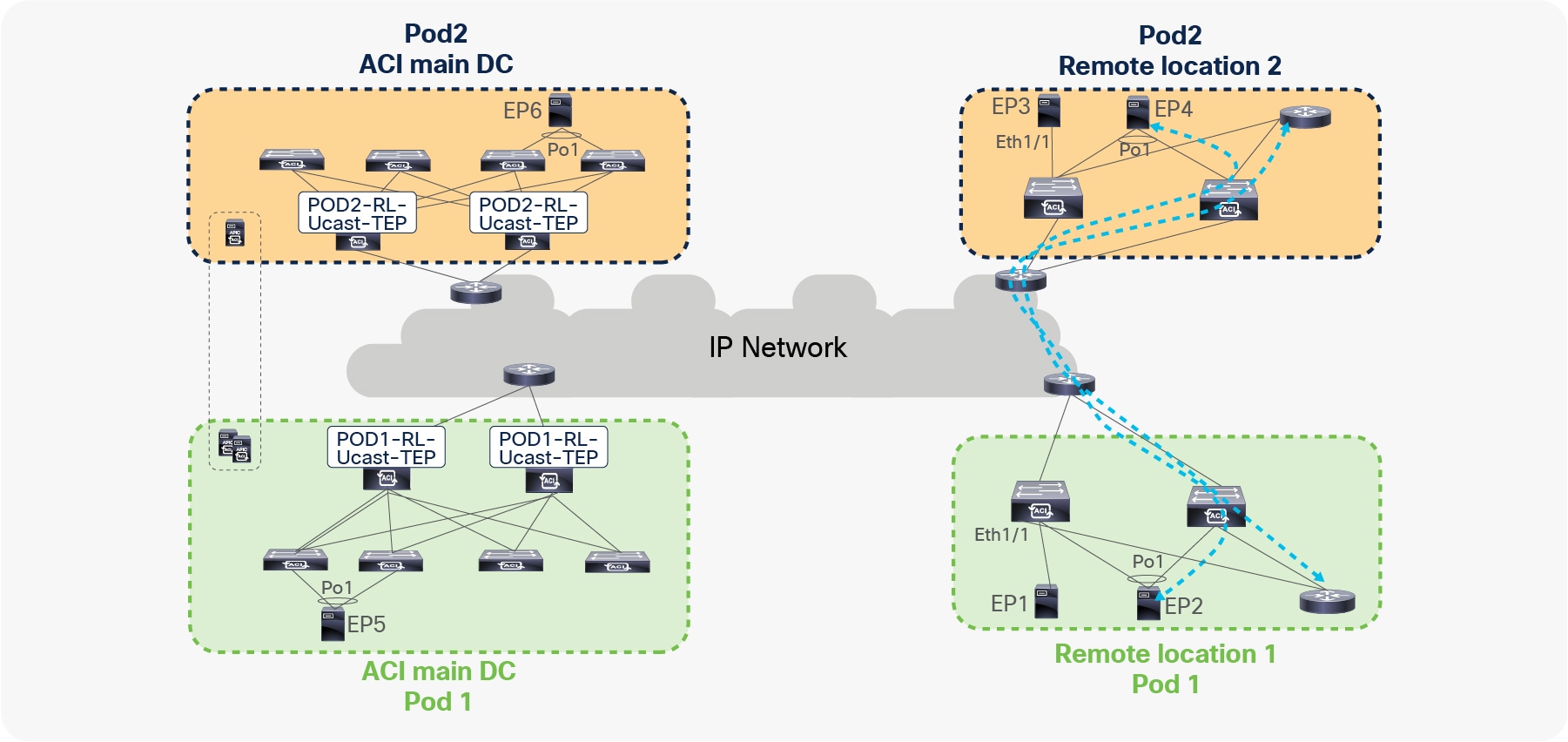
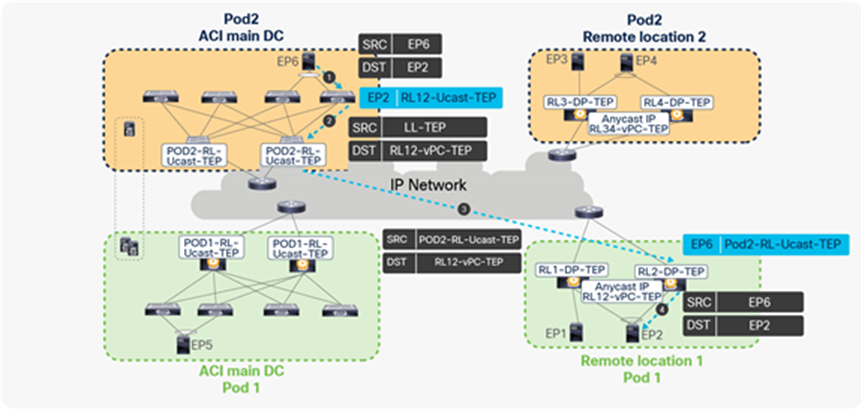
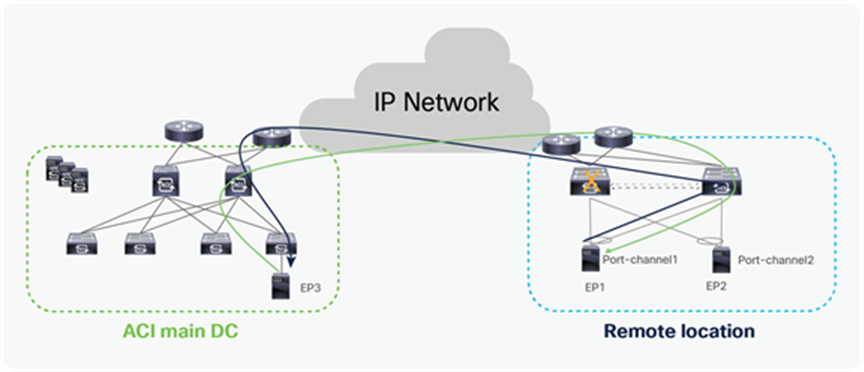
Starting from Cisco ACI release 4.1(2), communication between endpoints connected to separate RL pairs can be established directly through the IPN without hair-pinning to the main DC Pod. This applies to both scenarios where different RL pairs are associated to the same Pod or to separate Pods that are part of a Multi-Pod fabric.
In the below figure, Remote location 1 is logically attached to Pod1, and Remote location 2 is logically attached to Pod2. Traffic between the endpoints in Remote location 1 and Remote location 2 is directly forwarded without being hair-pinned to a spine. Similarly, traffic from Remote location of Pod1 to the local leaves of Pod2 or Remote location of Pod2 to the local leaves of Pod1 is also directly forwarded instead of going to the spines.
Remote leaf to remote leaf direct traffic forwarding
The following key changes were made in the remote leaf architecture to achieve remote leaf to remote leaf direct traffic forwarding:
● Each remote leaf automatically builds VXLAN tunnels with all the other remote leaf switches within the same Pod or across Pods within a single ACI Fabricall the other remote leaf switches within the same Pod or across Pods within a single ACI Fabric.
● Each remote leaf builds VXLAN tunnels with its logically connected Pod’s spine as before, but from Cisco ACI 4.1(2), it will also form VXLAN tunnels with the spines of all the other Pods within a single ACI Fabricit will also form VXLAN tunnels with the spines of all the other Pods within a single ACI Fabric.
● The remote leaf learns the endpoints of all the other remote leaves and local leaves with the next-hop of the tunnel toward other RLs or toward the spines of other Pods within a single ACI Fabric.
● Remote leaves forward traffic over these tunnels. Since traffic is being directly forwarded over these tunnels, traffic forwarding from RL to other RLs and local leaves within the ACI Fabric is direct instead of hair-pinning to spines.
Details on traffic forwarding are covered in the individual sections on RL-to-RL traffic forwarding within a single Pod, across Pods, and across ACI Fabrics.
Control plane for RL direct traffic forwarding
The following section explains the changes to the control plane that were made to support remote leaf to remote leaf direct traffic forwarding.
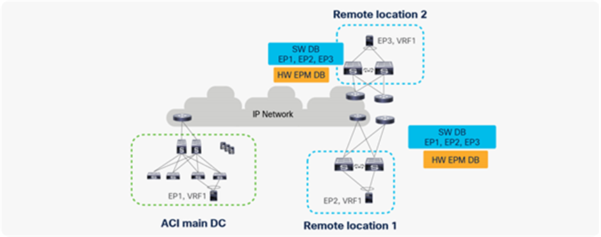
● When an endpoint is learned in the fabric, the COOP database on all of the spines is updated. Remote leaf builds a local software database (SW DB) from the COOP database of spines. This SW DB will have information about all of the endpoints (EPs) for all of the VRFs deployed on it. For example, in the figure below, the remote leaf in Remote location 1 has VRF1 deployed on it; therefore, it will build a local software database (SW DB) of all of the endpoints (EP1, EP2, EP3) in VRF1.
● The remote leaf also has a hardware endpoint manager (HW EPM) database where it keeps information about all of the remote endpoints to which local endpoints have established an active communication.
● The remote leaf updates the hardware endpoint manager (HW EPM) database from the software database based on data plane activity.
● When a remote leaf needs to send a packet towards a remote endpoint, it first performs a lookup for the destination in its HW EPM DB. If it finds an entry, it will forward the packet.
● If HW EPM DB does not have an entry for the destination, it will check the local SW DB. If the destination entry is available in SW DB, remote leaf updates its HW EPM DB and forwards the packet. Keeping the SW DB locally allows remote leaves to forward the packets even when the COOP connection to all of the spines has failed.
● If the destination of the packet is not present in the SW DB neither, the RL will either flood or send it to the spine proxy, based on BD settings to discover the silent host.
● Once the endpoint is discovered, COOP will be updated on the spine and EP information in SW DB will be updated on all of the remote leaves within the ACI site.
Control plane for remote leaf to remote leaf direct traffic forwarding
Remote leaf to remote leaf direct traffic forwarding within or across Pods in a fabric
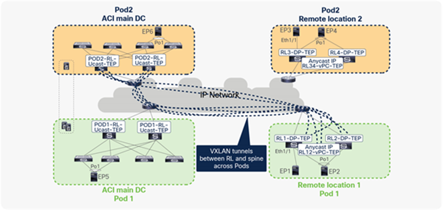
This section provides details about the process of traffic forwarding between remote leaf pairs within or across Pods in a fabric. As explained in the previous section, to achieve direct traffic forwarding between remote leaf pairs, remote leaf builds VXLAN tunnels automatically to the spines of all of the Pods that are part of the same fabric. A remote leaf forwards packets to all of the other remote leaves using these VXLAN tunnels.
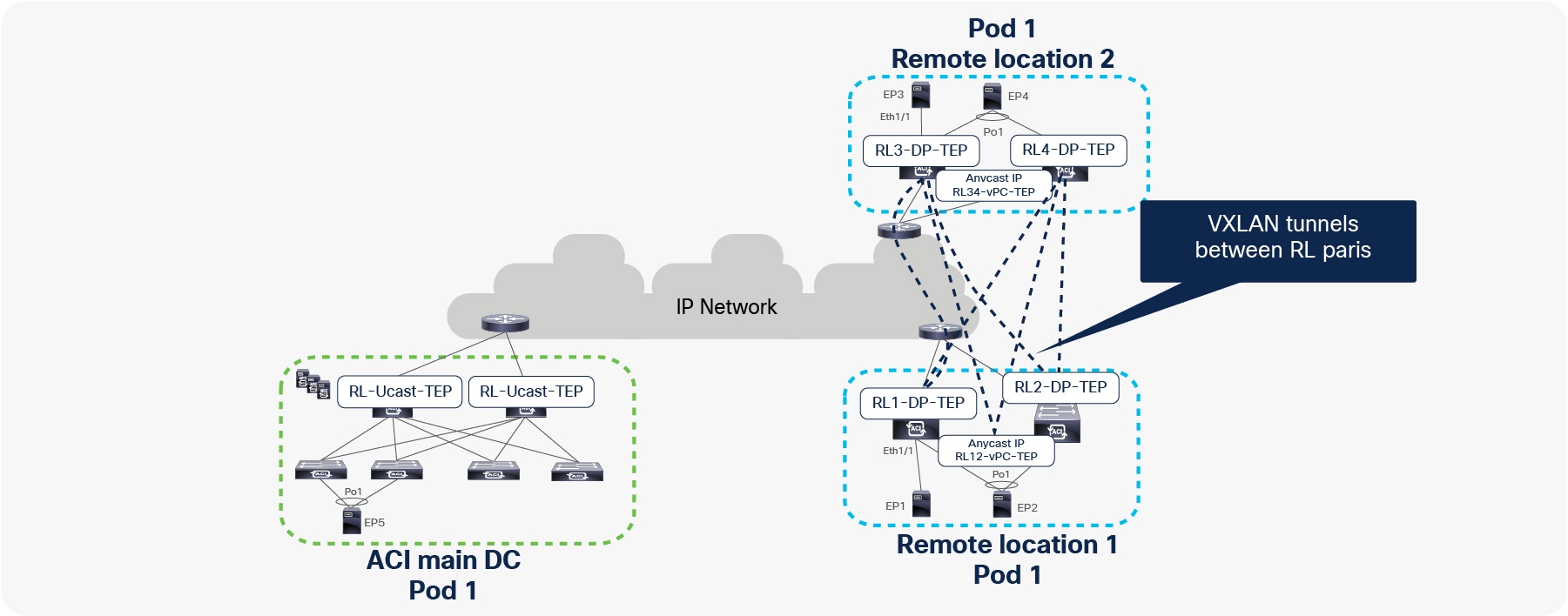
In the figure below, RL1, RL2, RL3, and RL4 are part of the same ACI Pod. Each RL builds a tunnel to all of the other RLs with the destination “anycast TEP for vPC” to send traffic to EPs that are connected using vPC. For example, in the figure below, RL1 and RL2 build a tunnel with a destination of RL34-vPC-TEP. Similarly, RL3 and RL4 build a tunnel with a destination of RL12-vPC-TEP.
Each RL also forms tunnels to all of the other RLs with RL-DP-TEP as the destination address to send traffic to EPs that are connected through orphan ports. For example, in the figure below, RL1 builds tunnels with destinations RL2-DP-TEP, RL3-DP-TEP, and RL4-DP-TEP. Similarly, all the other RLs also build tunnels with each other’s DP-TEPs.
VXLAN tunnels between remote leaf pairs for remote leaf to remote leaf traffic forwarding within a single Pod
Let’s understand how ACI forwards traffic under different scenarios between remote leaf pairs within and across Pods:
● Unicast traffic between remote leaf pairs associated to the same Pod
● Unicast traffic between remote leaf pairs associated to separate Pods of the same fabric
Unicast traffic between remote leaf pairs associated to the same Pod
In the figure below, EP1, EP2, EP3, and EP4 are part of the same BD. All of these EPs are not silent hosts; therefore, COOP on the spines has information about the location and next-hops of these EPs. As explained in the section “Control plane for RL direct traffic forwarding,” since the same VRF/BD is deployed on all of the RLs, each RL downloads information of all of the EPs into the local software DB (SW DB).
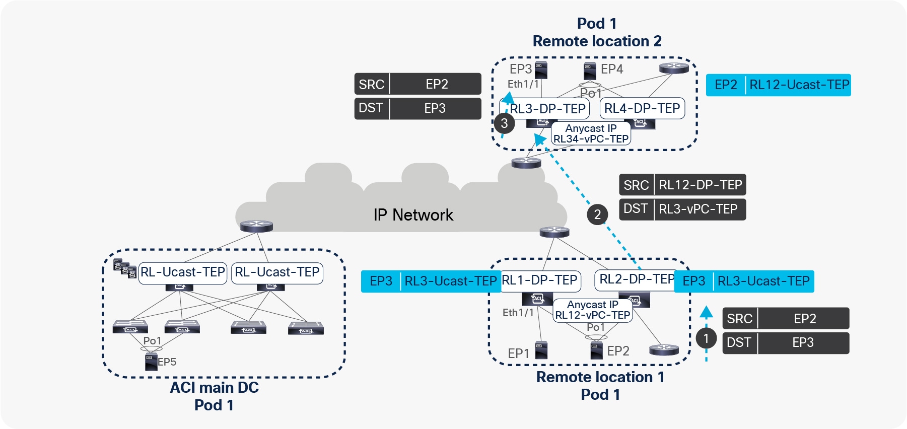
Traffic forwarding from EP2 to EP3 across different remote leaves
● Assume that EP2 is sending a packet to EP3. EP2 picks one of the links toward the remote leaf for forwarding the packet based on the hash.
● The packet from EP2 is received by one of the remote leaves. The receiving remote leaf performs a Layer 2 lookup of EP3’s MAC address in the HW EPM DB. It finds the next-hop for EP3’s MAC address as DP-TEP of RL3 (RL3-DP-TEP) in the SW DB. The remote leaf encapsulates the packet in the VXLAN header with the source TEP as RL12-vPC-TEP and the destination TEP as RL3-DP-TEP, and forwards to RL3.
● RL3 de-encapsulates this packet, performs a Layer 2 lookup in the MAC address table associated to the BD, and forwards it to EP2. RL3 also updates its HW EPM DB with EP2’s IP and MAC addresses with a next-hop of RL12-vPC-TEP.
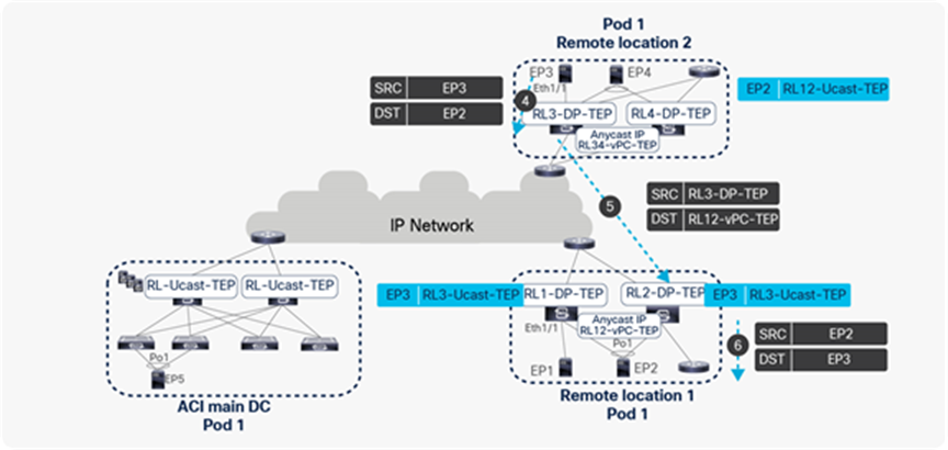
Traffic forwarding from EP3 to EP2 across different remote leaves
● Similarly, let’s look at EP3 sending a packet to EP2.
● RL3 performs a Layer2 lookup of the EP2 MAC address in its HW EPM DB. It finds the EP2 MAC address with the next-hop of RL12-vPC-TEP. RL3 then encapsulates and forwards the packet with the source TEP as RL3-DP-TEP and the destination TEP as vPC TEP of RL12 (RL12-vPC-TEP).
● The packet from RL3 will be received by either RL1 or RL2. The receiving RL updates its HW EPM DB with EP3’s IP and MAC addresses with a next-hop of RL3-DP-TEP. It also updates its vPC peer with the EP3 location. The receiving RL forwards the packet to EP2 after performing a Layer2 lookup.
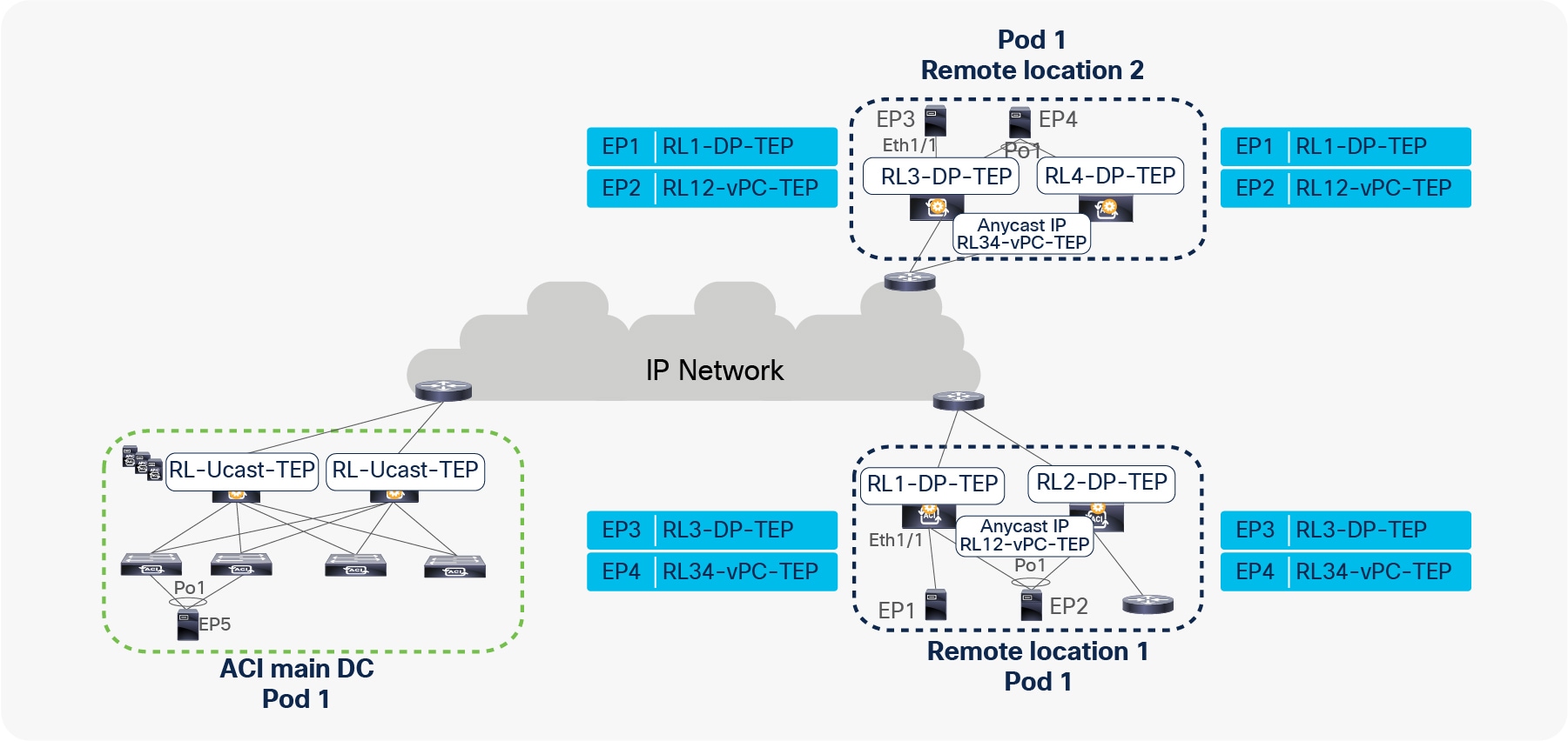
When EP1, EP2, EP3, and EP4 are forwarding packets to each other, the resulting HW EPM DB table on RL1, RL2, RL3, and RL4 is captured in the figure below.
EP learning on RL within a Pod
Unicast traffic between remote leaf pairs associated to separate Pods of the same fabric
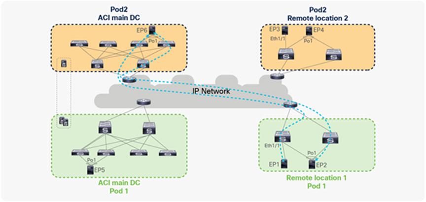
Traffic forwarding between remote leaf pairs works in the same way whether it is within a Pod or across Pods, as shown in the figure below. For example, in the figure, traffic between remote leaf pairs across Pods is forwarded directly.
Traffic forwarding between remote leaves across Pods
Remote leaf switches form VXLAN tunnels and learn from the EPs connected to remote leaf pairs in different Pods.
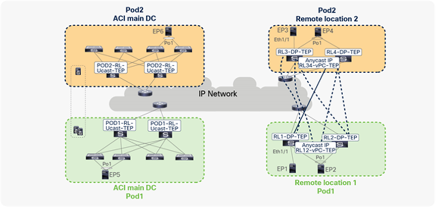
In the figure below, RL1 and RL2 are logically associated to Pod1, while RL3 and RL4 are logically associated to Pod2.
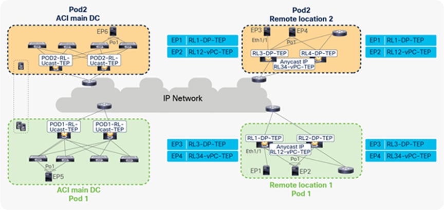
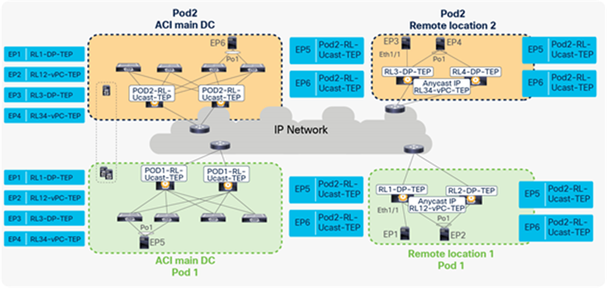
When EP1, EP2, EP3, and EP4 are forwarding packets to each other, the resulting EP table for RL1, RL2, RL3, and RL4 is captured in the figure below. Since EP2 and EP4 are connected through vPC, these EPs are learned with the next-hop as vPC-TEP. Because EP1 and EP3 are connected through orphan ports, these EPs are learned with next-hop as DP-TEP.
EP learning on RL across Pods
Unicast traffic forwarding between Remote and local leaf across Pods with RL direct forwarding
Remote leaf switches forward the traffic to the local leaves of all of the other Pods directly, without forwarding it to logically connected spines. The following figure shows this behavior.
Traffic forwarding between remote leaves and local leaves across Pods
To achieve direct traffic forwarding to the local leaves of other Pods, a remote leaf automatically forms VXLAN tunnels to the spines of all Pods, including the Pod where it is logically connected.
In the figure below, EP1, EP2, EP3, EP4, EP5, and EP6 are in same BD. On each RL, there will be a tunnel with the destination of the anycast IP address of the spines (RL-Ucast-TEP) of each Pod. This tunnels on the remote leaf is used to forward traffic from the remote leaf to the local leaves of all Pods.
Similarly, spines will have tunnels to each RL with a destination of RL-DP-TEP or RL vPC-TEP, based on whether the EP on the RL is connected using vPC or an orphan port. This tunnel on the spine is used to forward spine proxy–related packets from spine to RL.
VXLAN tunnels between RL and spine across Pods
Let’s understand how ACI forwards traffic under different scenarios between remote leaves and local leaves across Pods:
● Unicast traffic from local leaves to remote leaves across Pods
● Unicast traffic from remote leaves to local leaves across Pods
Unicast traffic from local leaves to remote leaves across Pods
Unicast traffic from local leaves to remote leaves across Pods works similarly to how it works in a single Pod. In the figure below, EP1, EP2, EP3, EP4, EP5, and EP6 are part of same BD. All these EPs are not silent hosts; therefore, COOP on the spines has information about the location and next-hops of these EPs. All the remote leaves will also download all information from the EPs into its local SW DB because the same VRF/BD is deployed on all of the remote leaves and local leaves.
Traffic forwarding from local leaves to remote leaves across Pods
● Assume that EP6 connected to Pod2’s local leaf is sending a packet to EP2 connected to a remote leaf of Pod1. EP6 picks one of the links toward the local leaf for forwarding the packet based on the hash.
● The receiving local leaf performs a Layer 2 look-up of EP2’s MAC address. It finds the next-hop for EP2’s MAC address as RL12-vPC-TEP in the HW EPM DB. The receiving leaf encapsulates the packet with the source TEP address as local leaf TEP (LL TEP) and the destination TEP as RL12-vPC-TEP.
● When the spine receives the packet with the destination TEP as RL12-vPC-TEP, it will update the source TEP as the anycast IP address of the spine (RL-Ucast-TEP) of Pod2. Spine forwards the packet to the anycast IP address of RL vPC pair (RL12-vPC-TEP).
● One of the RL receives the packet, de-encapsulates the VXLAN header, and forwards the packet to the locally attached host. RL learns the EP6 with the next-hop of the anycast IP address of the spine (RL-Ucast-TEP) of Pod2 and updates the information in HW EPM DB.
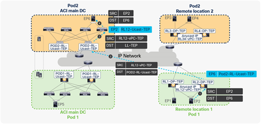
Unicast traffic from remote leaf to local leaf across Pods
Traffic forwarding from remote leaves to local leaves across Pods
● When EP2 sends a packet to EP6, EP2 picks one of the links to the remote leaf for forwarding the packet based on the hash.
● The packet from EP2 is received by one of the remote leaves. The receiving remote leaf performs a Layer 2 lookup of EP6’s MAC address in the HW EPM DB. It finds the RL-Ucast-TEP of Pod2 as the next-hop for EP6. The remote leaf encapsulates the packet in the VXLAN header with the source TEP as RL12-vPC-TEP and the destination as RL-Ucast-TEP of Pod2, and forwards it to the spines of Pod2.
● One of the spines receives this packet. The spine performs a lookup for the inner header destination (EP2’s MAC address). It updates the destination TEP as the local leaf TEP (TEP) and forwards the packet to the leaf connected to EP6.
● The local leaf forwards the packet to the locally connected endpoint (EP6) and updates its hardware EPM DB with the EP2 with a next-hop of RL12-vPC-TEP.
When EP1, EP2, EP3, and EP4 begin bidirectional communications with EP6, the resulting EP table on the local leaf and remote leaf will look as shown in the following figure.
EP learning between remote leaves and local leaves across
Remote leaf with Cisco ACI Multi-Site
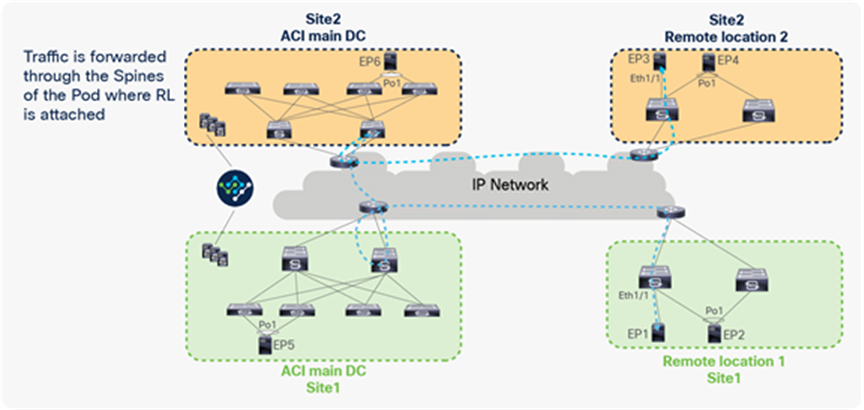
Remote leaf and Cisco ACI Multi-Site are supported together, starting from Cisco ACI 4.1(2). Packets from RL to another site’s remote leaf or local leaf are forwarded through the spines of the logically connected Pod. RL does not build VXLAN tunnels with the RLs or the spines of the other site, to avoid building VXLAN tunnels across sites. For this reason, packets from RL to other sites are forwarded through the spines of the logically attached Pod’s spines, as shown in the figure below.
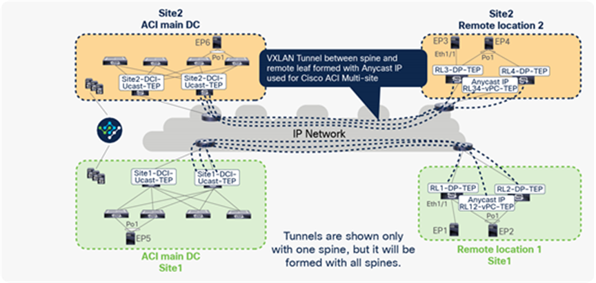
Traffic between remote leaf pairs across Sites
Let’s understand how ACI forwards traffic between remote leaf pairs across sites. In the example below, RL1 and RL2 are part of ACI Site1, and RL3 and RL4 are part of ACI Site2. The remote leaf in each site forms a VXLAN tunnel with spines of the Pod where the remote leaf is logically connected; the destination TEP of this tunnel would be the Anycast IP address of the spine used for Cisco ACI Multi-Site (DCI-Ucast-TEP).
When the remote leaf is deployed with Cisco ACI Multi-Site, this tunnel is used to communicate to all of the EPs connected in the other sites. This tunnel on the remote leaf is also used to communicate with EPs connected to the local leaves within the same site when the remote leaf is deployed with Cisco ACI Multi-Site.
In the figure below, RL1 and RL2 form VXLAN tunnels using the anycast IP address of the spine for the Multi-Site (Site1-DCI-Ucast-TEP) of its Pod. Similarly, RL3 and RL4 form VXLAN tunnels with the anycast IP address of the spine for the Multi-Site (Site2-DCI-Ucast-TEP) of its Pod. Please note that each Pod in the ACI site has a separate DCI-Ucast-TEP address. This is the anycast IP address assigned to all spines in that Pod. In the figure below, VXLAN tunnels are shown only with single spines, but same tunnels are formed with all of the spines.
VXLAN tunnels from RL to ACI main DC with Cisco ACI Multi-Site
In the figure above EP1, EP2, EP3, EP4, EP5, and EP6 are part of the same VRF. All of these EPs are not silent hosts; therefore, COOP on the spines has information about the location and next-hop of these EPs. All of the RLs will also download all of the EPs’ information into its local SW DB because the same VRF/BD is deployed on all of the RLs and local leaves.
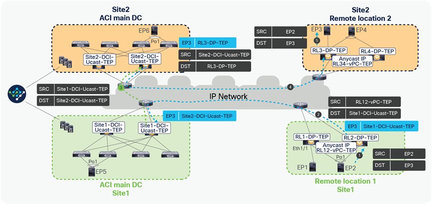
Unicast traffic between RL pairs across Sites
Traffic forwarding between remote leaf pairs across Sites
● Assume that EP2 is sending a packet to EP3 with the source IP as the local IP EP2 and the destination as EP3’s IP. EP2 picks one of the links toward the remote leaf for forwarding the packet based on the hash.
● The packet from EP2 is received by one of the remote leaves. The receiving remote leaf performs a Layer 3 lookup of EP3’s IP in the HW EPM DB. It finds the next-hop for EP3’s IP as Site1-DCI-Ucast-TEP. Each Pod in the ACI site has a separate DCI-Ucast-TEP address. This is the anycast IP address assigned to all of the spines in that Pod. The remote leaf encapsulates the packet in the VXLAN header with the source TEP as RL12-vPC-TEP and the destination TEP as Site1-DCI-Ucast-TEP. This packet can be received by the spines of the logically connected Pods of RL1 and RL2.
● The receiving spine performs a lookup of EP3’s IP. It finds the next-hop for EP3’s IP as Site2-DCI-Ucast-TEP. It changes the source TEP to Site1-DCI-Ucast-TEP and the destination TEP to Site2-DCI-Ucast-TEP and forwards the packet to the spines of the logically connected Pods of RL3 and RL4.
● The receiving spine of Site2 performs a Layer3 lookup of EP3’s IP. It finds the next-hop for EP3’s IP as RL3-DP-TEP. It changes the source TEP to Site2-DCI-Ucast-TEP and the destination TEP to RL3-DP-TEP.
● RL3 receives this packet, de-encapsulates it, and sends it to EP2. It will also update its HW EPM DB with EP2, with a next-hop of Site2-DCI-Ucast-TEP.
A similar process is performed when a packet is sent from EP3 to EP2.
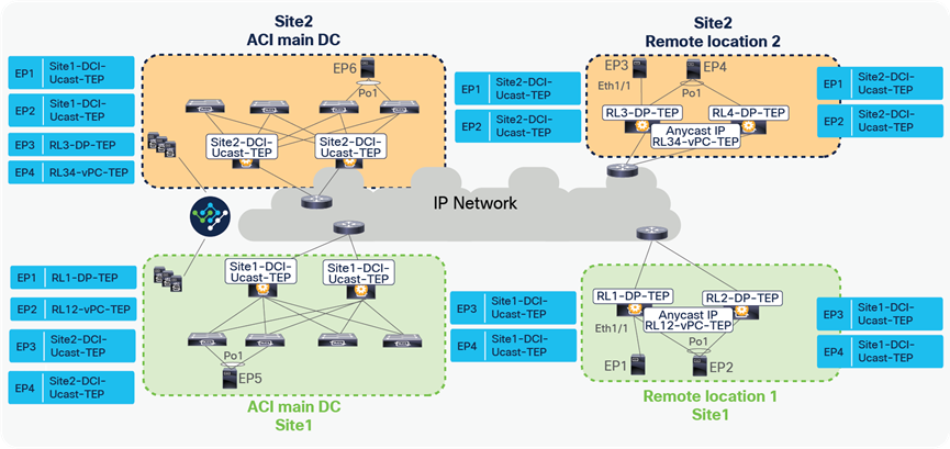
When EP1, EP2, EP3, and EP4 are forwarding packets to each other, the resulting EP tables on RL1, RL2, RL3, and RL4 is captured in the figure below.
EP learning between remote leaf pairs across sites
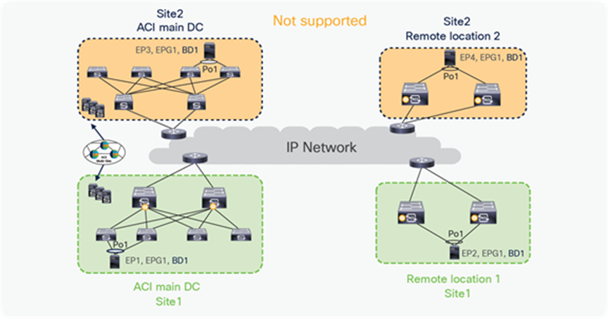
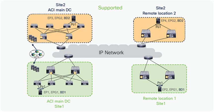
Please note that stretching a bridge domain (BD) between remote leaf (RL) nodes associated to a given site (APIC domain) and leaf nodes that are part of a separate site of an ACI Multi-Site deployment (whether the leaf nodes are local or remote) is not supported, and a fault is generated on APIC to highlight this restriction. This applies independently from the fact that BUM flooding is enabled or disabled when configuring the stretched BD on the Nexus Dashboard Orchestrator (NDO). However, a BD can always be stretched (with BUM flooding enabled or disabled) between remote leaf nodes and local leaf nodes belonging to the same site (APIC domain).
In the figure below, EP1, EP2, EP3, and EP4 belong to different sites, but these are part of the same EPG, BD. This combination is not supported.
BD stretched across sites with RL
In the figure below, EP1, EP2 in Site1 are part of EPG1, BD1 that is stretched across the ACI main DC and the remote location. Similarly, EP3, EP4 in Site2 are part of EPG2, BD2, which is again stretched across RL and the ACI main DC. This combination is supported because in this combination the BD is not stretched across the sites and RL.
BD stretched within an ACI site with Multi-Site
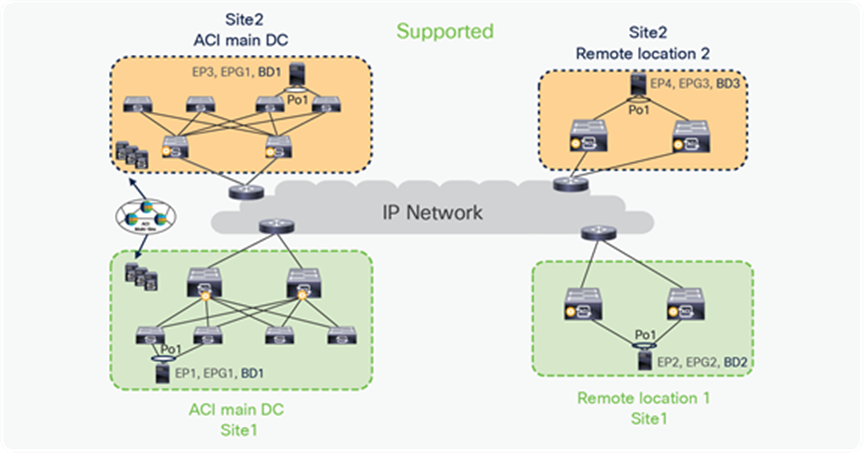
In the figure below, EPG1, BD1 is stretched across sites, but this EPG and BD are not deployed on RL. This combination is supported.

BD stretched across sites without stretching on RL
Broadcast, Unknown Unicast and Multicast (BUM) traffic with RL direct when BD is in flood mode
The section below covers how two endpoints that are connected to remote leaves forward Broadcast, Unknown Unicast and Multicast (BUM) traffic with RL direct enabled and when BD is in flood mode. This section assumes that EP2 and EP3 are silent hosts, and that each is connected to a different remote leaf pair. The following section takes an example of an ARP request being forwarded from EP2 to EP3. The following figure shows EP2 and EP3 connected to different Pods, but the section explains the behavior whether endpoints are connected within same Pod or across Pods. BD stretching is not supported across ACI sites.
BUM traffic forwarding for silent host when BD is in flood mode and RL direct is enabled
● When EP2 sends an ARP request for EP3, it picks one of the links toward the remote leaf for forwarding the ARP request packet based on the hash.
● Since EP3 is a silent host, EP3’s information is not available in the COOP DB, SW DB on RL, and HW EPM DB on the receiving remote leaf. As explained in the section “Control plane for RL direct traffic forwarding”, the receiving remote leaf tries to resolve the ARP for EP3.
● The receiving remote leaf will encapsulate the ARP request packet in the VXLAN header and forward it to all other RLs within and across Pods using VXLAN tunnels. It will encapsulate the ARP packet with the source TEP as RL-vPC-TEP (RL12-vPC-TEP) and the destination TEP as DP-TEP for each RL. All of the RLs that receive this packet will make an entry for EP2 with a next-hop of RL12-vPC-TEP.
● Each receiving remote leaf will de-encapsulate the VXLAN packet and flood the ARP request in the locally attached segment to resolve the ARP for EP3.
● The remote leaf that receives the ARP request directly from EP2 will also send a single packet to the spines in its Pod with the destination TEP address in the VXLAN header as the anycast address of the spine (RL-Mcast-TEP) and with the source as RL12-vPC-TEP.
● The spines flood the packet to all of the leaves in its local Pod using the BD multicast address. Every configured BD has a unique multicast address assigned inside the ACI Pod. When a spine floods the ARP packet with BD multicast IP, it reaches only the leaves that have endpoints actively connected to this BD. Each receiving leaf de-encapsulates the VXLAN packet and floods ARP request in the locally attached segment to resolve the ARP for EP3.
● One of the spines of the Pod where remote leaf is logically attached also floods the ARP request to the spines in the other Pods using inter-pod multicast (IPN). This will make sure the ARP request is received by all of the Pods within a single site. Each receiving leaf in the Pod de-encapsulates the VXLAN packet and floods the ARP request in the locally attached segment to resolve the ARP for EP3. Each receiving leaf will learn EP3’s information with a next-hop of RL12-vPC-TEP.
Please note that spines are configured with an ACL entry that blocks forwarding BUM traffic to any other RL if BUM traffic is received from an RL. This will make sure that RLs do not receive duplicate copies of BUM traffic from an RL as well as from the spines. Duplicate copies of the same packet would have created EP flap on RLs.
The process described above ensures that the following ARP request generated by EP2 and received by the spines can then be directly forwarded to the leaf where EP3 is connected, allowing the completion of the ARP exchange between EP1 and EP3 (as discussed in the unicast traffic forwarding section).
Broadcast, Unknown Unicast and Multicast (BUM) traffic with RL direct when BD is in proxy mode
The section below covers how two endpoints that are connected to remote leaves forward Broadcast, Unknown Unicast and Multicast (BUM) traffic with RL direct enabled and when BD is in proxy mode. This section assumes that EP2 and EP3 are silent hosts and that each is connected to a different remote leaf pair. The following section takes an example of an ARP request being forwarded from EP2 to EP3. The following figure shows EP2 and EP3 connected to different Pods, but the section explains the behavior whether endpoints are connected within the same Pod or across Pods. BD stretching is not supported across ACI sites.
BUM traffic forwarding for silent host when BD is in proxy mode and RL direct is enabled
● When EP2 sends an ARP request for EP3, it picks one of the links toward the remote leaf for forwarding the ARP request packet based on the hash.
● Since EP3 is a silent host, EP3’s information is not available in the COOP DB, SW DB on RL, and HW EPM DB on the receiving RL. As explained in the section “Control plane for RL direct traffic forwarding,” the receiving RL tries to resolve the ARP for EP3.
● The receiving remote leaf will encapsulate the ARP request packet in the VXLAN header and forward it to the spine proxy with a source TEP as RL-vPC-TEP (RL12-vPC-TEP) and a destination TEP as Pod1-RL-Ucast-TEP.
● The spine forwards the ARP request to the destination leaf if it has information about EP3 in its database; otherwise, it sends a glean message to all of the leaves, including the remote leaves in its site.
● The glean message triggers each leaf to send an ARP request on all of the local interfaces in the BD that received the ARP request. The spine will also send one copy of the glean message to the spines of the other Pods. Those Pods’ spines will forward the glean packet to the all of the leaves, including the remote leaves.
● This triggers an ARP reply from EP3. When the leaf receives the ARP response, it updates its hardware table and sends a COOP update to the spine with the EP3 location.
The process described above ensures that the following ARP request generated by EP2 and received by the spines can then be directly forwarded to the leaf where EP3 is connected, allowing the completion of the ARP exchange between EP1 and EP3 (as discussed in the unicast traffic forwarding section).
Inter-VRF traffic between remote leaf switches
In ACI, inter-VRF traffic always gets forwarded to the spine proxy function to find the policy information of the packet destined to a different VRF; therefore, when the endpoints are connected to the remote leaf nodes, inter-VRF traffic gets forwarded through the spines in the main data center. However, an optimization is introduced from Cisco ACI Release 4.0(1), allowing inter-VRF traffic between endpoints connected to remote leaf switches to be locally forwarded.
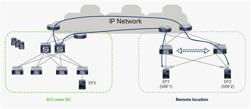
Inter-VRF traffic within a remote leaf pair before Cisco ACI Release 4.0
However, from Cisco ACI Release 4.0(1), inter-VRF traffic between endpoints connected to remote leaf switches is locally forwarded through a WAN router. The reason packets are sent to an upstream router is that, when an incoming packet from EP1 in VRF1 arrives at RL, it will not have the policy information of EP2, which is in VRF2; because of this, RL cannot forward the packet to EP2 directly. To overcome this, RL forms a new tunnel to itself through the WAN router. All inter-VRF packets are sent, through this tunnel, from one VRF to a second, receiving VRF. In the figure below, RL sends packets in VRF1 through this tunnel, to be received by VRF2, so that it can discover the policy and contract information of EP2.
Inter-VRF traffic within a Remote-leaf pair from Cisco ACI Release 4.0(1)
VMM Domain Integration and vMotion with remote leaf
ACI integrates with Multiple VMM (Virtual Machine Manager) domains. With this integration, the APIC controller pushes the ACI policy configuration such as networking, telemetry monitoring and troubleshooting to switches based on the location of virtual machines. The APIC pushes the policy to the remote leaf just like it does for local leafs. A single VMM domain can be created for compute resources connected to both the ACI main DC Pod and remote leaf switches. VMM-APIC integration is also used to push a VDS to those hosts managed by the VMM and dynamically create port-groups as a result of the creation of EPGs and their association to the VMM domain. This allows to enable mobility (‘live’ or ‘cold’) for virtual endpoints across different compute hypervisors.
Note: It is worth noticing that VM mobility doesn’t require the use of VMM integration, you can integrate virtualized servers with ACI via physical domain integration, and VM mobility works just fine.
Note: Virtual instances in same EPG or L2 domain (VLAN) can be behind local leaf as well as a remote leaf. When a Virtual instance moves from a remote leaf to a local leaf or vice versa, the APIC controller detects the leaf switches where virtual instance has moved and pushes the associated policies to the new leaf. All VMM and container domain integration supported for local leaf are supported for remote leaf as well.
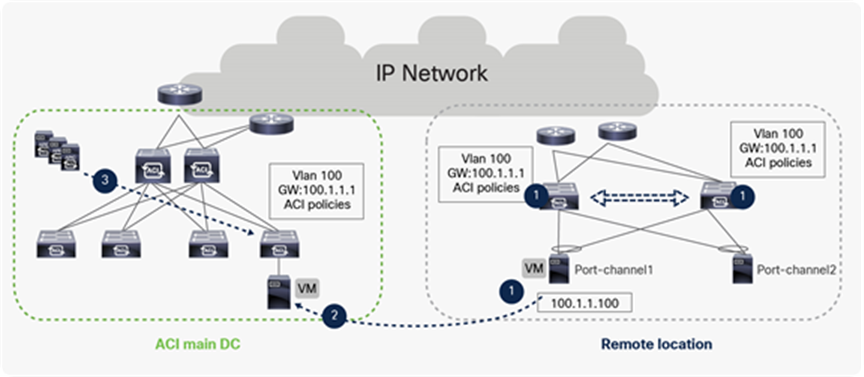
vMotion between RL to ACI main DC
The above example shows the process of vMotion with ACI Fabric. The following events happen during a vMotion event:
● The VM has IP address “100.1.1.100” and a default gateway of 100.1.1.1 in VLAN 100. When the VM comes up, ACI fabric configures the VLAN and the default gateway of the Leaf switches where the VM is connected. The APIC controller also pushes the contract and other associated policies based on the location of the VM.
● When the VM moves from a remote leaf to a local leaf, the ACI detects the location of VM through VMM integration.
● Depending on the EPG specific configuration, the APIC controller may need to pushes the ACI policy on the Leaf for successful VM mobility or policy may already be existing on destination leaf.
The following picture is the snapshot from the APIC controller where a single VMM domain is extended from a local leaf in ACI main DC to a remote leaf.
Snapshot from APIC for an EPG with VMM domain and VM connected to both local and remote leaf
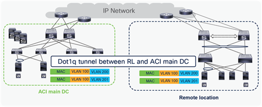
Dot1q tunnel between remote leaf and ACI main DC
For a colocation use case, customers may need to connect multiple VLANs between the ACI main DC and the remote leaf. For this use case, there may be a need to connect thousands of VLANs between ACI main DC and remote locations. In this scenario, if a single VLAN is mapped to an EPG, then the fabric may have a huge EPG scale that may exceed the supported scale. To avoid such a situation, starting from Cisco ACI Release 4.2(4), a single dot1q tunnel can be created between the RL and ACI main DC to carry traffic for multiple VLANs. Using a dot1q tunnel can reduce the overall scale of EPGs required on the fabric.
Dot1q tunnel between RL and ACI main DC
Starting from Cisco ACI Release 5.1(3), L3 multicast is supported on remote leaf. The configuration of L3 multicast on RL remains the same as for local leaf, but there are differences in the way L3 multicast packet forwarding works for RL. Remote leaf switches use head-end replication (HREP) for forwarding L3 multicast packets. HREP is already used for forwarding Layer-2 multicast to remote leaf switches. This feature adds HREP forwarding for multicast-enabled VRFs. The main difference between RL and ACI Multi-Pod in terms of L3 multicast forwarding is that ACI Multi-Pod uses PIM Bidir in IPN, while remote leaf uses HREP tunnels to forward L3 multicast traffic.
Both Local and remote leaf forward L3 multicast to the VRF GIPo multicast address, and remote leaf maps HREP tunnels to the VRF GIPo address (the Group IP outer address). VRF GIPo is allocated implicitly based on configuration. There is one GIPo for the VRF and one GIPo for every BD under that VRF. All multicast traffic for PIM-enabled BDs is forwarded using the VRF GIPo. This includes both Layer 2 and Layer 3 IP multicast.
All spines within a pod use one anycast TEP address as the HREP destination. L3 multicast packets sent from a remote leaf to its associated pod will be sent to this anycast TEP address. Each remote leaf switch has a unique TEP address for receiving HREP multicast packets. spines and other remote leaf switches send L3 multicast packets to this TEP address.
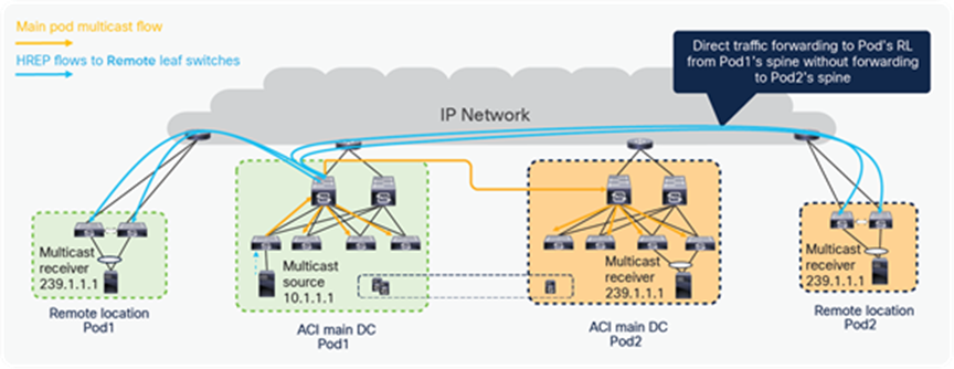
In the figure below, the multicast source is in Pod1, and the receivers are in Pod2 LL and on RL of Pod1 and Pod2. The multicast source in Pod1 forwards traffic to the connected leaf, which forwards it to the spine that is the designated forwarder for the VRF GIPo and forwards multicast traffic to the IPN. Multicast traffic is forwarded within the IPN and received by the designated port on the spine of Pod2, which sent the IGMP join for the VRF GIPo. Pod2’s spine, after receiving the traffic, forwards the traffic to all the leaves in Pod2 that have VRF deployed for the interested L3 Multicast traffic.
Pod1’s spine also forwards multicast traffic to all the RL switches directly within and across Pods, using HREP tunnels, as shown below. Please note that RL direct traffic forwarding must be enabled for L3 multicast on RL. RL direct traffic forwarding is also the default behavior starting from Cisco ACI Release 5.0 and cannot be disabled.
L3 multicast traffic forwarding from source in ACI main DC to RLs and other Pods
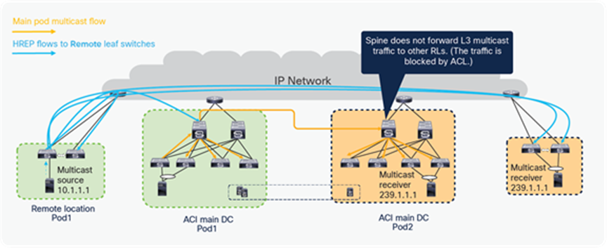
If the source is connected to RL, as shown in the diagram below, then RL sends L3 multicast traffic to its logically connected Pod’s spine using HREP tunnels. The spine forwards the multicast traffic to other Pods using the VRF GIPo group. RL also forwards traffic to all the other RLs in the fabric, using HREP tunnels. Please note that the spine does not forward traffic back to RLs if the traffic is received from another Pod or the RLs, to avoid a traffic loop.
L3 multicast traffic forwarding from source on RL to ACI main DC Pods and other RLs
External connectivity from remote leaf
External connectivity from a Remote DC to the outside network (like the WAN or the Internet) can be provided through a L3Out configured on remote leaf switches. The following diagram provides an example of how a L3Out on remote leaf works.
Control plane with L3Out on RL
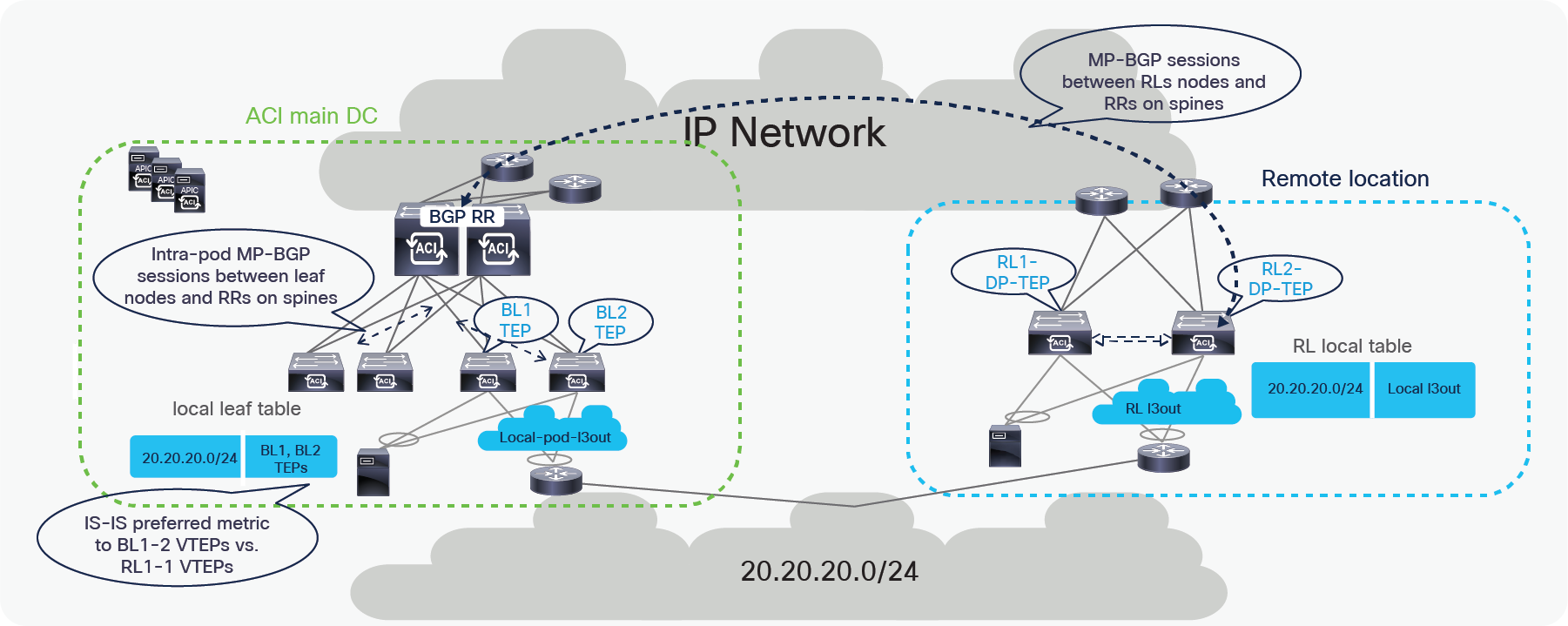
In the above example, the remote leaf has a L3Out connection to an external router. The external router is connected to remote leaf switches over a vPC with an SVI. Remote leaf switches learn external subnets from router with the next-hop of the Router SVI.
The remote leaf advertises the externally learnt prefixes to spines through the MP-BGP VPNv4 session between RLs and spines. Spines in the ACI main DC act as a BGP Route Reflector (RR) for both remote leaves and Local leaves. The spines advertise the prefixes received from the remote leaf nodes to the local leaf switches through Intra-Pod MP-BGP VPNv4 sessions.
The ACI main DC can also have a L3Out connection to connect to the external Layer 3 domain. Server Leaves in the ACI main DC learn the external prefixes with the next-hop of the local Border Leaf TEP addresses. The ACI Main Pod prefers BL1-TEP and BL-2-TEP compared to RL1-DP-TEP and RL2-DP-TEP because the route cost is better in the first case.
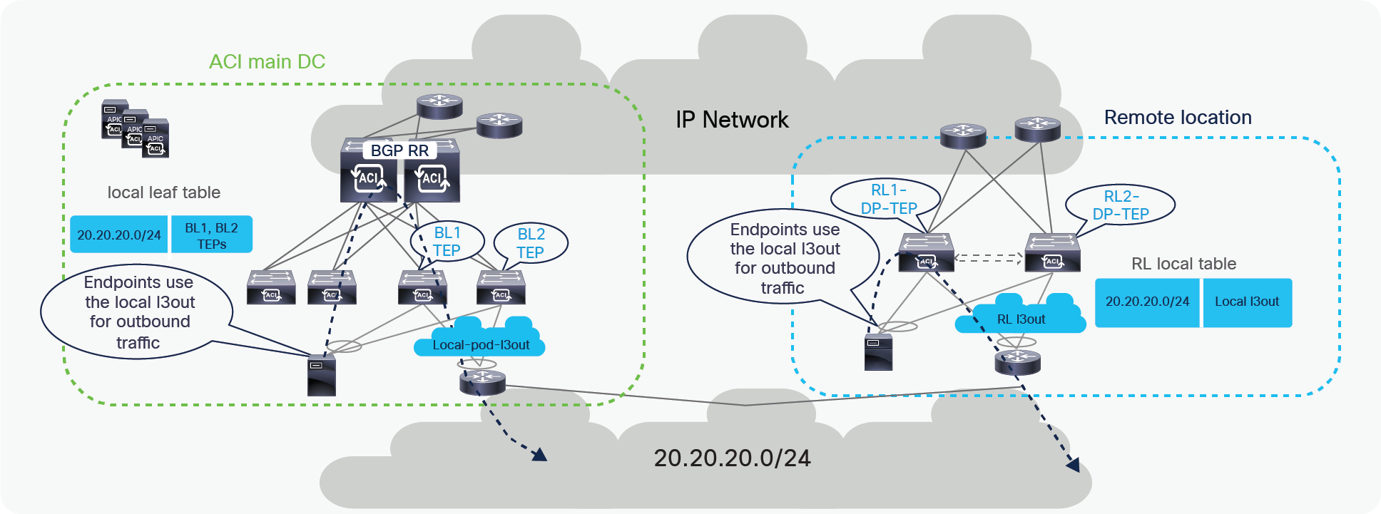
As a consequence, endpoints connected to either remote leaf nodes or local leaf nodes use by default the L3Out local to them for external connectivity. However, the ACI main DC L3Out can act as a backup for the RL, and vice versa.
Data plane with L3Out on RL
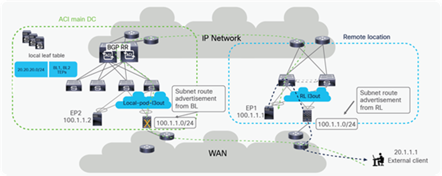
Both Remote DC and ACI main DC may have L3Outs for WAN connectivity and there could be cases where hosts belonging to the same IP subnet are deployed in both locations. In this case, as explained in the previous section, the local L3Out connection will normally be preferred for outbound traffic from DC to WAN. However, since the Border Leaf nodes in the ACI main DC Pod and the remote leaf switches may be advertising the same IP subnet prefixes toward the external Layer 3 network domain, incoming traffic may take a sub-optimal path. In such scenario, incoming traffic destined to an endpoint connected to the remote leaf switches might in fact ingress the L3Out in the ACI main DC, if endpoints in the same IP subnet of the remote endpoint are connected in the Main DC. The traffic would then be forwarded from the ACI main DC to the endpoint connected to the remote leaf switches via the IPN; when the endpoint replies, the outbound traffic will take the path via the local L3Out creating an asymmetric traffic path behavior that may cause traffic drop if perimeter stateful devices (like firewalls) are deployed between the leaf switches and the external routers.
Possible traffic asymmetry with same prefix being advertised from RL and ACI main DC
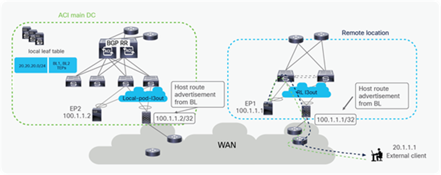
A possible solution to this problem is providing a more granular advertisement of routing information into the WAN, whereby the BL nodes in the ACI main DC would advertise not only the IP subnet but also the specific endpoints belonging to that IP subnet and discovered in the main Pod. In the same way, the RL nodes would advertise into the WAN the IP subnet and the specific host routes for endpoints belonging to that IP subnet and locally discovered.
This host routes advertisement capability is available on ACI leaf switches starting from ACI software release 4.0 and ensures that both ingress and egress paths are symmetric and use the same Local L3Out connection (as shown in the diagram below). With this capability, it is hence possible to deploy independent pairs of perimeter firewalls in the main DC and at the remote leaf location.
Solution for traffic asymmetry with same prefix being advertised from RL and ACI main DC
Failure handling in remote leaf deployment
This section captures the different failure scenarios and explains how the network behaves during those failures.
Spine failure in main DC
Remote leaf switches uses the anycast IP address of the spine to send unicast or BUM traffic toward the ACI Pod. If a spine fails, alternatively available spine can accept traffic from remote leaf and forward to final destination. Leaf switches in main DC are attached to multiple spine, and uses ECMP to pick a spine to forward traffic. When one spine fails, local leaf switches can pick alternative available spine to forward traffic to remote leaf.
Traffic forwarding when spine fails in ACI main DC
Remote leaf failure
It’s always recommended to use vPC for remote leaf switches. When the remote leaf nodes are part of a vPC domain, packets from the spines are forwarded to the anycast IP of the remote leaf vPC pair. If one remote leaf fails, traffic will be rerouted toward the second remote leaf that can accept and forward packets to attached host.
Similarly, when a host is dual-homed to the remote leaf pair through vPC, the failure of a remote leaf node would simply cause the re-shuffling of flows on the link connecting to the second RL switch.
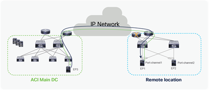
Traffic forwarding when one remote leaf fails
Upstream router on RL is lost
It’s recommended to use multiple upstream router for the redundancy purpose. When one of the upstream router fails, remote leaf switches can use alternative available upstream router for traffic forwarding.
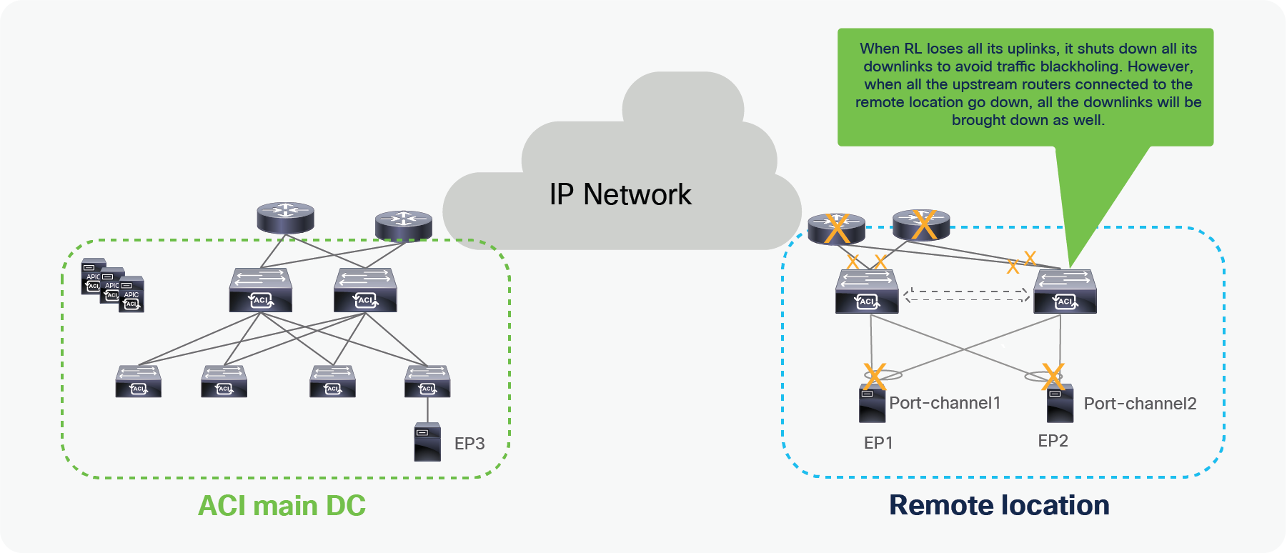
Upstream router failure at remote location
All Upstream routers connected to RL are lost
When remote leaf switches are configured with vPC domain, and end host/L3Out is connected to remote leaf switches with vPC, if all upstream routers fail, then all the uplinks of the RL nodes will fail, and as a consequence the vPC links toward the endpoints are brought down. This behavior is to avoid traffic blackholing when the EP attached to the remote leaf can send packets, but the remote leaf cannot forward due to uplink failure.
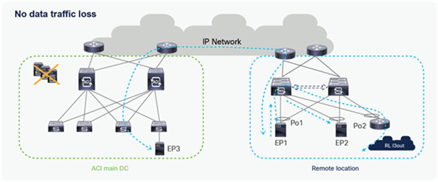
Failure scenario when RL loses all upstream routers, or all uplink connections
Failure of APIC controller reachability in a single Pod
When all APIC controllers in a single Pod are lost, remote leaf switches will not experience any data-plane or control plane failures. They will continue to forward traffic to all destinations; however, new configurations cannot be applied since APIC controller connectivity is down. Since all APIC controllers are down, operations and visibility to the remote leaf will be lost; however, users can login to the remote leaf using an out-of-band or console connection.
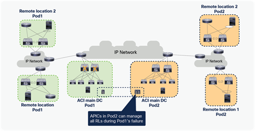
Remote leaf with failure of all APIC controllers
Failure of APIC controller reachability, with Multi-Pod and RL-direct
Starting from Cisco ACI Release 4.2(2), remote leaf can communicate to all the ACI Pods directly without depending on the spines in the logically connected DC. Multi-Pod will typically be used with APIC controllers distributed across Pods. In case the remote leaf loses reachability to all of the APIC controllers of its associated Pod, it can still be managed from the APIC controllers of the other available Pods as shown in the figure below.
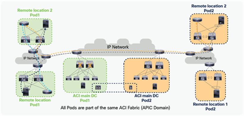
Remote leaves managed by an alternate Pod’s APIC controller
Failure of all-spine reachability, with Multi-Pod and RL direct enabled
Deployment of remote leaf with Multi-Pod is recommended to build a resilient design. Reachability to the spine could fail either due to the failure of the IP Network between remote leaf and spine, or due to the failure of all of the spines in a logically attached Pod of the remote leaf.
In such a case, starting from Cisco ACI Release 4.2(2), the remote leaf will keep forwarding traffic to all destinations, as shown in the figure below.
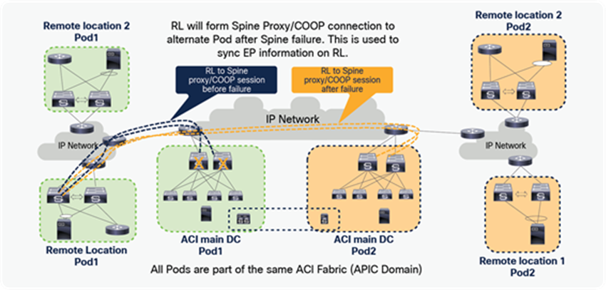
Traffic forwarding behavior on RL during spine failure with Multi-pod and RL direct enabled
During a spine-connectivity failure, the remote leaf continues to forward traffic using local SW DB and EPM DB; however, it uses an alternate Pod’s spine as a control plane. When the remote leaf loses connectivity to the spines of the Pod it was originally associated with, it will try to build COOP and spine proxy connection to the alternative available spines. Using an alternate COOP connection, Release leaf downloads the SW DB and gets the latest EP information. An alternate spine proxy connection is used for BUM traffic forwarding, forwarding traffic toward silent hosts, ARP, etc.
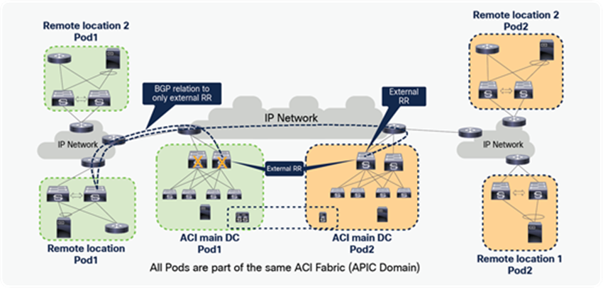
Remote leaf building COOP/spine proxy
In a Multi-Pod setup, the user must configure the spines in more than one Pod as external BGP Route Reflectors (RRs). The remote leaf builds an MP-BGP session with spines that are configured as external RRs. In a steady state, the remote leaf builds a BGP relationship with the spines in multiple Pods. If the remote leaf loses connectivity to its logically connected Pod’s spine, it will continue to have MP-BGP sessions with other Pod’s spines that are configured as external RRs. This allows the remote leaf to receive the external prefixes from the spines of the alternate Pod in the event of failure of its logically connected Pod.
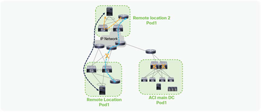
Remote leaf building BGP connections with multiple spines across Pods
Failures of all-spine reachability, with single Pod and RL direct enabled
When a remote leaf loses reachability to its logically connected Pod’s spines either due to spine failure or due to reachability failure in the IPN, it will have the following traffic forwarding behavior:
● The remote leaf continues to forward traffic between the existing and the new EPs connected directly to it.
● It can forward traffic to destinations that are connected to other remote leaf pairs if those EPs are learned in the SW DB or HW EPM of the remote leaf before the spine’s reachability failure. However, if the existing learned remote EPs time out from the SW DB, communication will fail. The SW DB timeout on the remote leaf is 15 minutes.
● If there are new EPs that are learned on one remote leaf pair, new EPs cannot be synced to other remote leaf pairs when reachability to the spines is down. As explained in the section “Control plane for RL direct traffic forwarding,” the remote leaf depends on spine Proxy/COOP to learn new EPs connected to other remote leaf pairs or ACI main DC.
● Because the L3Out prefixes of one remote leaf pair are learnt on other remote leaf pairs using spines that act as MP-BGP RRs, spine-reachability failure causes failure of L3Out to L3Out traffic between remote leaf pairs.
● EPs belonging to different VRFs are learned on the remote leaf using the COOP connection; therefore, inter-VRF communication across RL pairs will break down when spine reachability is down.
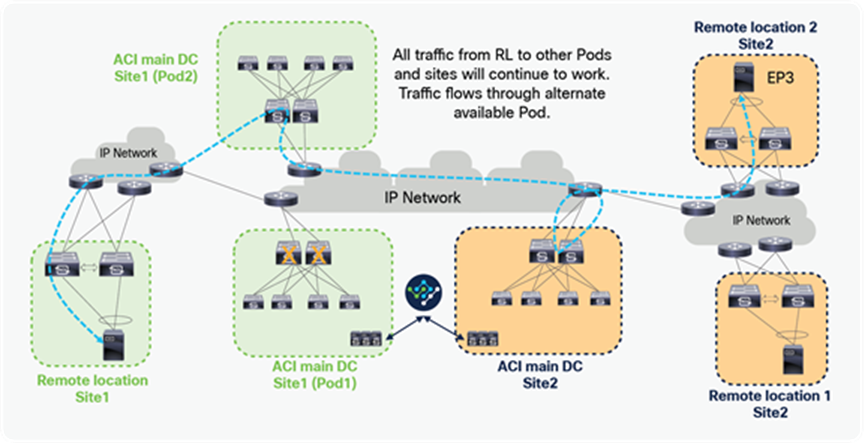
Traffic forwarding behavior on RL during spine failure with single Pod and RL direct enabled
Failure of all-spine reachability, with Multi-Site
When the remote leaf solution is deployed with Multi-Site, redundancy during spine-reachability failure will depend on whether the solution is deployed with single Pod or Multi-Pod. If Multi-Site is deployed with Multi-Pod, and the remote leaf loses connectivity to the spines of its logically connected Pod, then the remote leaf continues to forward traffic to all destinations within and across ACI sites. Details of remote leaf redundancy behavior are the same as explained in the section “Failure of all-spine reachability, with Multi-Pod and RL direct enabled”.
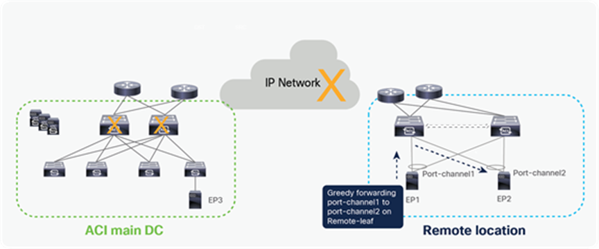
Traffic forwarding on remote leaves during all-spine failure with Multi-Site and RL direct enabled
If Multi-Site is deployed with Single Pod, and the remote leaf loses connectivity to spines of its logically connected Pod, then RL redundancy behavior will be the same as explained in section “Failure of all-spine reachability, with single Pod and RL direct enabled.”
Failure of all-spine reachability, with single Pod and without RL direct
Reachability between remote leaves and spines can fail for multiple reasons, mentioned below; therefore, building redundancy for connectivity between remote leaves and the spine is recommended. Reachability to the spine can fail either due to an IP network failure between remote leaves and a spine or to a failure of all spines in the ACI main data center.
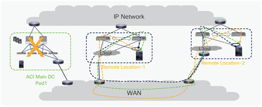
No reachability between remote leaf and spine
When remote leaf switches are configured with the vPC domain and end-host/L3Out is connected to the remote leaf switches with vPC, the following behavior will be seen during failure:
● Traffic to known endpoints/prefixes connected to the remote leaf will continue to work.
● Traffic destined to all EPs connected to local leaves and other remote leaves will be dropped, because this traffic gets forwarded through the spine without RL-direct.
● Traffic to the L3Out prefixes locally learned on the remote leaves will continue to work fine.
● No configuration can be added to remote leaves since connectivity to APIC is lost.
Failure of all-spine reachability, with all traffic via local L3Out
When traffic from remote leaf to all the Pods and remote leaf nodes is forwarded through local L3Out, then there is no data traffic impact when a remote leaf loses connectivity to the spines of its logically connected Pod. It continues to forward traffic to all other Pods and remote leaf switches through the local L3Out connection.
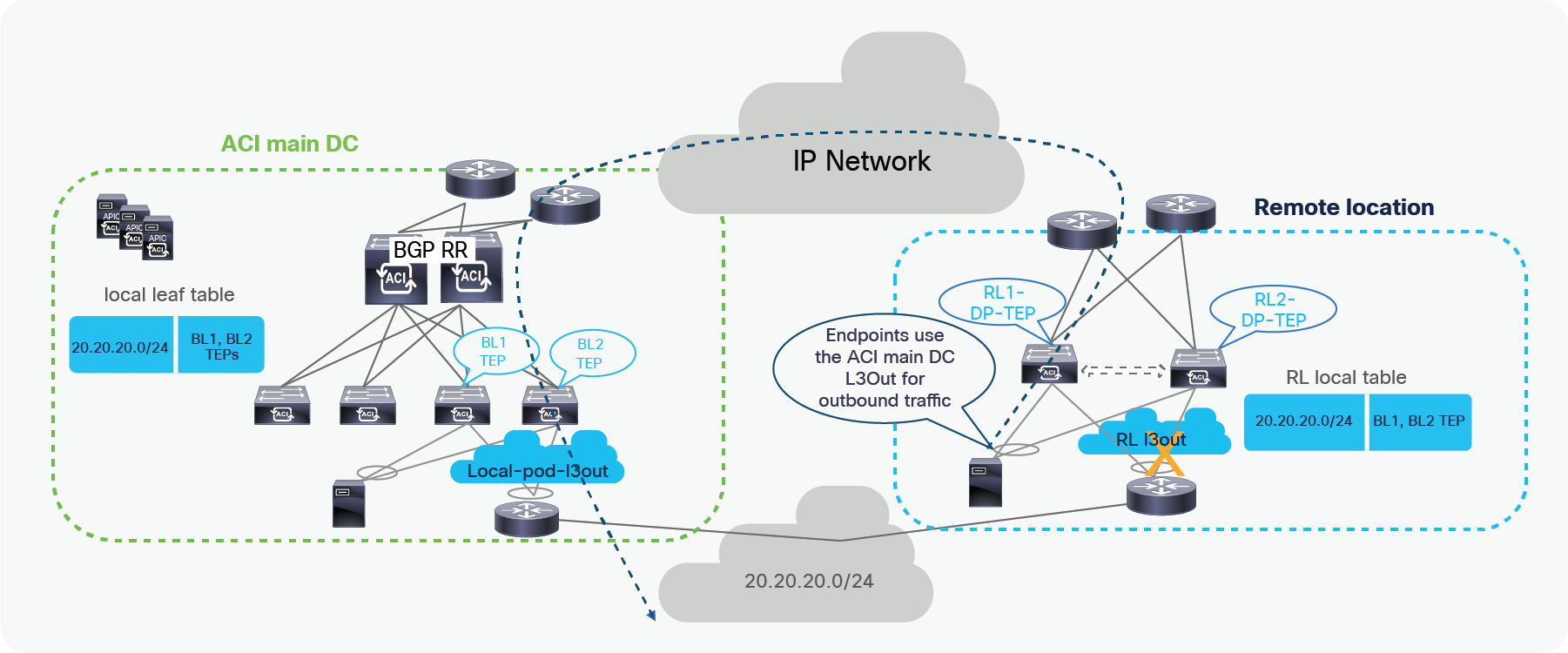
Complete failure of local L3Out at remote leaf (WAN isolation scenario)
Remote leaf switches receive BGP updates for the prefix learned through L3Out in the ACI main DC using an MP-BGP session with the spines. However, when the same prefix is learned over Local L3Out, the endpoints connected to the remote leaf switches prefer Local L3Out over the L3Out connection in the ACI main DC if the remote leaf is peering with peering OSPF/EIGRP or when it is receiving a prefix with the same BGP attributes from both local L3Out and the ACI main DC.
When the local L3Out connection fails, outbound traffic can instead use the L3Out connection in the ACI main DC, as shown in the figure below.
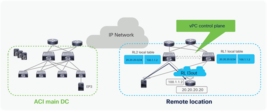
Traffic forwarding when RL loses local
L3Out interface failure when L3Out on remote leaf is configured over vPC
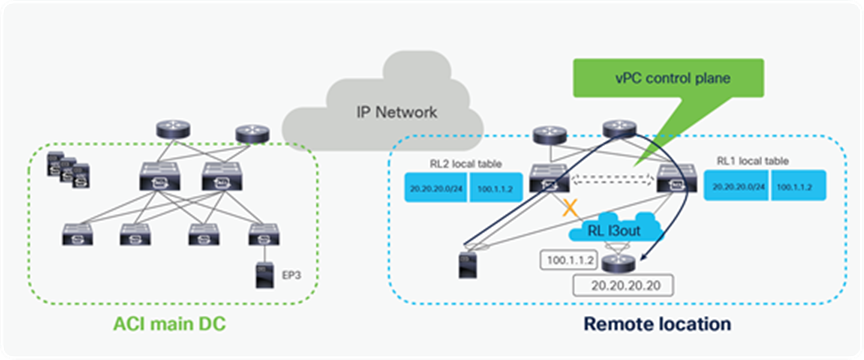
Control plane learning when L3Out is configured over SVI with vPC on RL
Like local switches, remote leaf switches can also be configured with L3Out over SVI with vPC. In this configuration, each RL uses local next-hop reachable via SVI to reach the external prefix.
When the local interface toward the external router goes down, the SVI interface on RL does not go down, and next-hop (that is, the external router’s connected interface) becomes reachable via the upstream router.
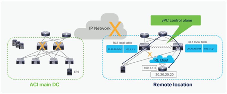
Traffic forwarding when L3Out interface fails on RL
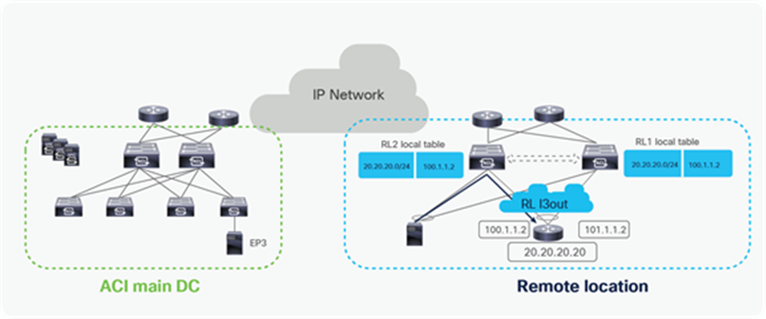
Traffic forwarding when L3Out interface fails on RL along with connectivity to ACI main DC
When L3Out on remote leaf is configured over SVI with vPC, it does not depend upon spine MP-BGP neighborship to provide reachability information for locally learned external prefixes. This ensures that even if IP Network connectivity is lost, external prefixes are reachable via local L3Out.
L3Out interface failure when L3Out on remote leaf is configured over Routed interface

Control-plane learning when L3Out is configured on RL over routed interface/sub-interface
Like local switches, remote leaf switches can also be configured with L3Out over a routed interface or sub-interface. In this configuration, each RL will use local next-hop reachable to reach the external prefix.
When the local interface toward the external router goes down, a remote leaf can use its peer RL to reach the external prefix. The remote leaf receives the external prefix update via the MP-BGP session with the spine.
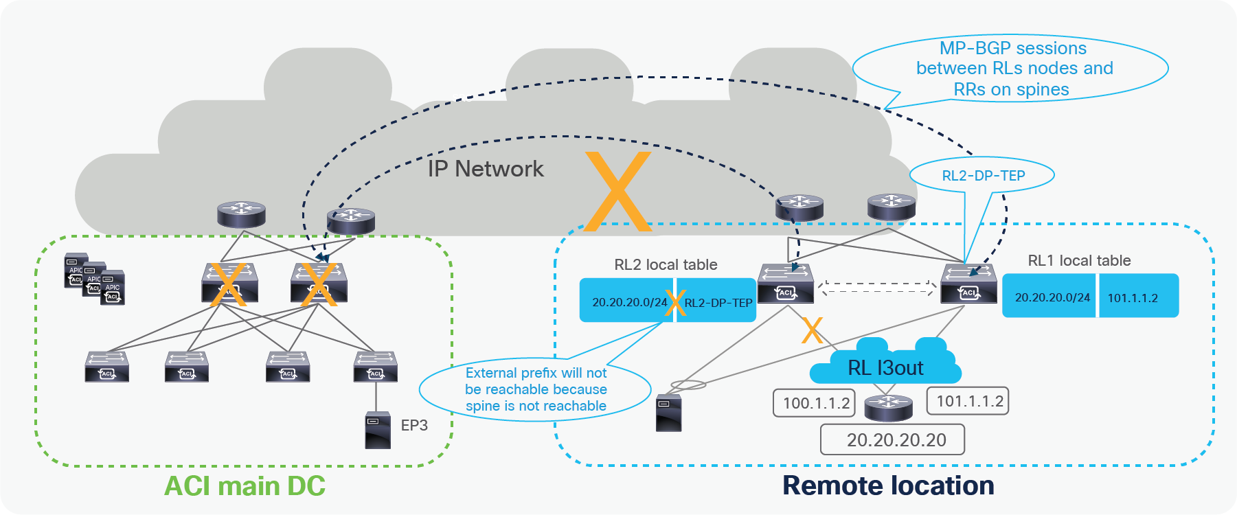
Traffic forwarding when L3Out interface fails on RL
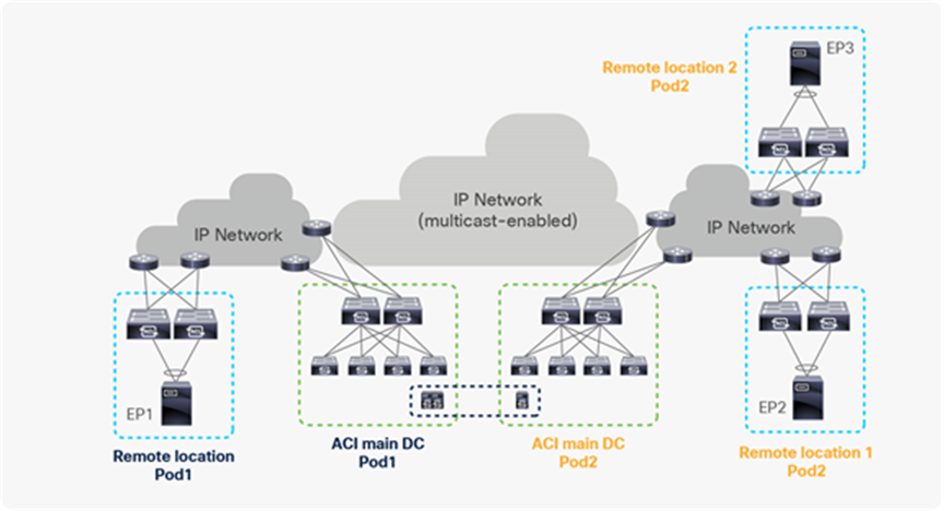
Traffic forwarding when L3Out interface fails on RL along with connectivity to ACI main DC
If both local leaf and IPN connectivity fail at the same time, then the remote leaf cannot receive BGPs update from the spine for the external prefix. In this case, RL will not have reachability to the external prefix.
The problem shown in above the figure will be seen only in a single Pod scenario from Cisco ACI 4.2(2).
Starting from Cisco ACI 4.2(2), in a Multi-Pod scenario, with RL-direct enabled, remote leaf builds BGP sessions with spines across different Pods. This will ensure that, even when all spines of the logically connected Pod go down, BGP sessions on RL will be up with alternate Pods.
Please note that if a remote leaf loses connectivity to all Pods’ spines due to a problem in the IP Network, then the remote leaf cannot receive BGP updates from any spine for the external prefix if both the local L3Out interface and IP Network fail together. In that case, the remote leaf won’t have reachability to the external prefix.
Cisco remote leaf solution allows the centralized management and consistent policy for Remote DCs without the investment of APIC controllers and spines for these smaller size DCs. Networking, Security, Monitoring, Telemetry and troubleshooting Policies that are defined for Main DC can be used for Remote DCs as well that are connected to ACI main DC over IP Network.
For more information about the ACI architecture, refer to the documentation available at the following links:
https://www.cisco.com/c/en/us/solutions/data-center-virtualization/application-centric-infrastructure/index.html.
ACI Multi-Pod and remote leaf integration before Cisco ACI 4.1(2)
Before Cisco ACI 4.1(2), when remote leaf switches were used in the Multi-Pod solution, there was a need to configure a separate sub-interface on the spine switches and a separate VRF in IPN. This was to make sure that unicast and multicast traffic took the same path and that next-hops of endpoints did not flap.
Starting from ACI release 4.1(2), user does not need to configure VLAN-5 with Multi-Pod if remote leaf Direct Traffic Forwarding is enabled. Please note that remote leaf direct traffic forwarding is default and only behavior starting from ACI 5.0.
The following section provides more details about remote leaf with ACI Multi-Pod before Cisco ACI 4.1(2).
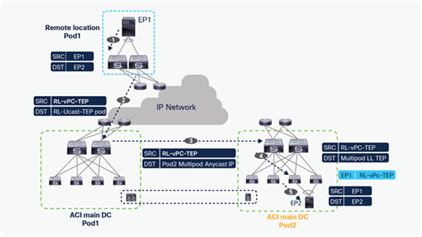
Remote leaf with ACI Multi-Pod
When remote leaf switches are used in Multi-Pod solution, there is a need to configure separate sub-interface on spine switches and a separate VRF in IPN. This is to make sure unicast and multicast traffic takes the same path and the next-hop of endpoint does not flap. The following section provides more details about remote leaf with ACI Multi-Pod.
Reasons to keep separate sub-interfaces on spines and a separate VRF on IPN
To understand the reason for this requirement, we need to analyze what would happen when using a normal configuration on the spines required for building a Multi-Pod fabric (that is, leveraging a single L3Out in the infra tenant with only sub-interfaces tagging traffic on VLAN 4, and connecting the spines with the IPN devices). In this scenario, we are going to consider how those different traffic flows would be handled.
In the example below, a remote leaf is associated to Pod1 (“pod1” in the figure below). The Multi-Pod local leaf term is being used for a leaf in the remote Pod (pod2).
Unicast traffic within the BD from the remote leaf to Multi-Pod local leaf
● Unicast traffic within BD from Multi-Pod local leaf to remote leaf.
● L2 multicast traffic from Multi-Pod local leaf to remote leaf.
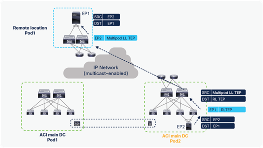
Unicast traffic within BD from remote leaf to Multi-Pod local leaf
The figure above highlights the unicast traffic flow between EP1, which is connected to the remote leaf switches, and endpoint EP2, which is part of the ACI Multi-Pod fabric but connected in a Pod different from the one to which the RL nodes are logically associated (in this above example, the remote leaf switches are part of Pod1). The following sequence of events happens to establish a unicast traffic flow between EP1 and EP2. The assumption here is that EP1 and EP2 are part of same BD and IP subnet.
● EP1 sends a unicast packet to EP2 with a source MAC address of EP1 and a destination MAC address of EP2.
● The packet is received by one of the remote leaf nodes, which performs a Layer 2 lookup of EP2’s MAC address in its hardware table and finds that EP2 is reachable via the anycast VTEP address enabled on all the spines of its Pod (Pod1). The remote leaf switch encapsulates this packet in the VXLAN header and forwards it toward the Multi-Pod fabric with the source IP being the anycast IP address of the remote leaves (RL-vPC-TEP), and destination IP the anycast IP address of the spines in Pod1 (RL-Ucast-TEP).
● One of the spines in Pod1 receives the packet. The spine performs a lookup in the COOP database and finds that EP2 is part of Pod2. As a consequence, it changes the destination IP address to the anycast IP address of the spines in Pod2.
● One of the spines in Pod2 receives this packet, performs the lookup in the COOP database and forwards it to the local leaf where EP2 is located. At the same time, the spine changes the destination IP to the TEP address of local leaf (Multi-Pod LL TEP) of Pod2 where EP2 is located.
● The local leaf of Pod2 receives the packet and updates the hardware table with EP1 information with next-hop of RL-vPC-TEP, based on the source TEP of the packet, and forwards traffic to EP1.
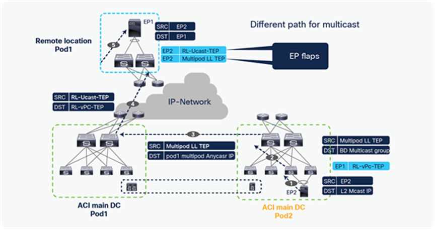
Unicast traffic within BD from Multi-Pod local leaf to Remote
In the figure above is shown, instead, the return unicast traffic flow from EP2 to EP1, which includes the following sequence of events:
● EP2 sends a unicast packet to EP1, with the source MAC address of EP2 and the destination MAC address of EP1.
● The Multi-Pod local leaf receives this packet and does a Layer 2 lookup of EP1 in its hardware table and finds the next-hop as the anycast IP address of the remote leaf (RL-vPC-TEP), based on the data-plane learning previously described. The leaf switch encapsulates the packet in the VXLAN header with the source TEP as its own TEP (Multi-Pod LL TEP) and the destination as RL-vPC-TEP. Since remote leaf and Multi-Pod are sharing the same IP Network in the same VRF, Multi-Pod local leaf can directly send the packet to remote leaf switches over the IP Network.
● One of the remote leaf switches receives the packet and updates the EP2 information in its local hardware table with next-hop of Multi-Pod LL TEP learned from the source TEP of the VXLAN encapsulated packet.
● The remote leaf then forwards the packet to the attached host EP1.
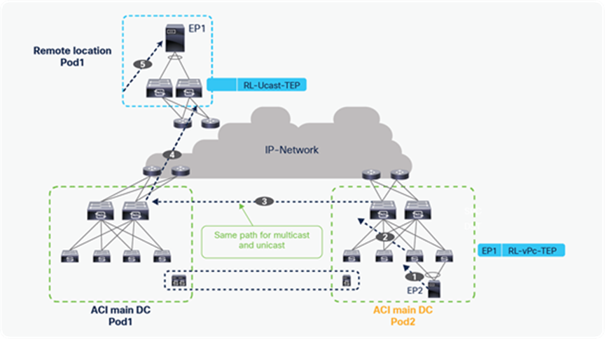
L2 multicast traffic from a Multi-Pod local leaf to remote leaf
Let’s see now what happens when a multicast traffic flow is sent from EP2 to EP1 without configuring a separate sub-interface and a separate VRF in IPN.
● EP2 sends multicast traffic with the source MAC address as EP2 and the destination as L2 multicast MAC address.
● Multi-Pod leaf receives this packet and checks for the bridge domain (BD) of EP2; it then forwards the packet to the multicast IP address of the BD.
● Local spines in Pod2 receive the packet and forward it to the spines of Pod1 with the BD multicast group as the destination. Since remote leaves are logically associated to Pod1, Pod2 spines cannot do HREP of L2 multicast traffic directly to remote leaves.
● The spine in Pod1 forwards the packet to remote leaf after encapsulating the multicast packet in a unicast VXLAN packet with the source as the anycast IP address of the spines (RL-Ucast-TEP) and the destination as the anycast IP address of the remote leaves (RL-vPC-TEP).
● The remote leaf now learns the EP2 with next-hop of RL-Ucast-TEP. It already learned EP2 with Multi-Pod-LL TEP during the unicast traffic flow.
As a consequence, without configuring separate sub-interfaces and separate VRFs in the IP Network, unicast and multicast traffic will take different paths. This causes the EP information to flap on remote leaves.
The remote leaf solution with Multi-Pod creates separate paths for remote leaves and ensures that unicast and multicast traffic take the same path.
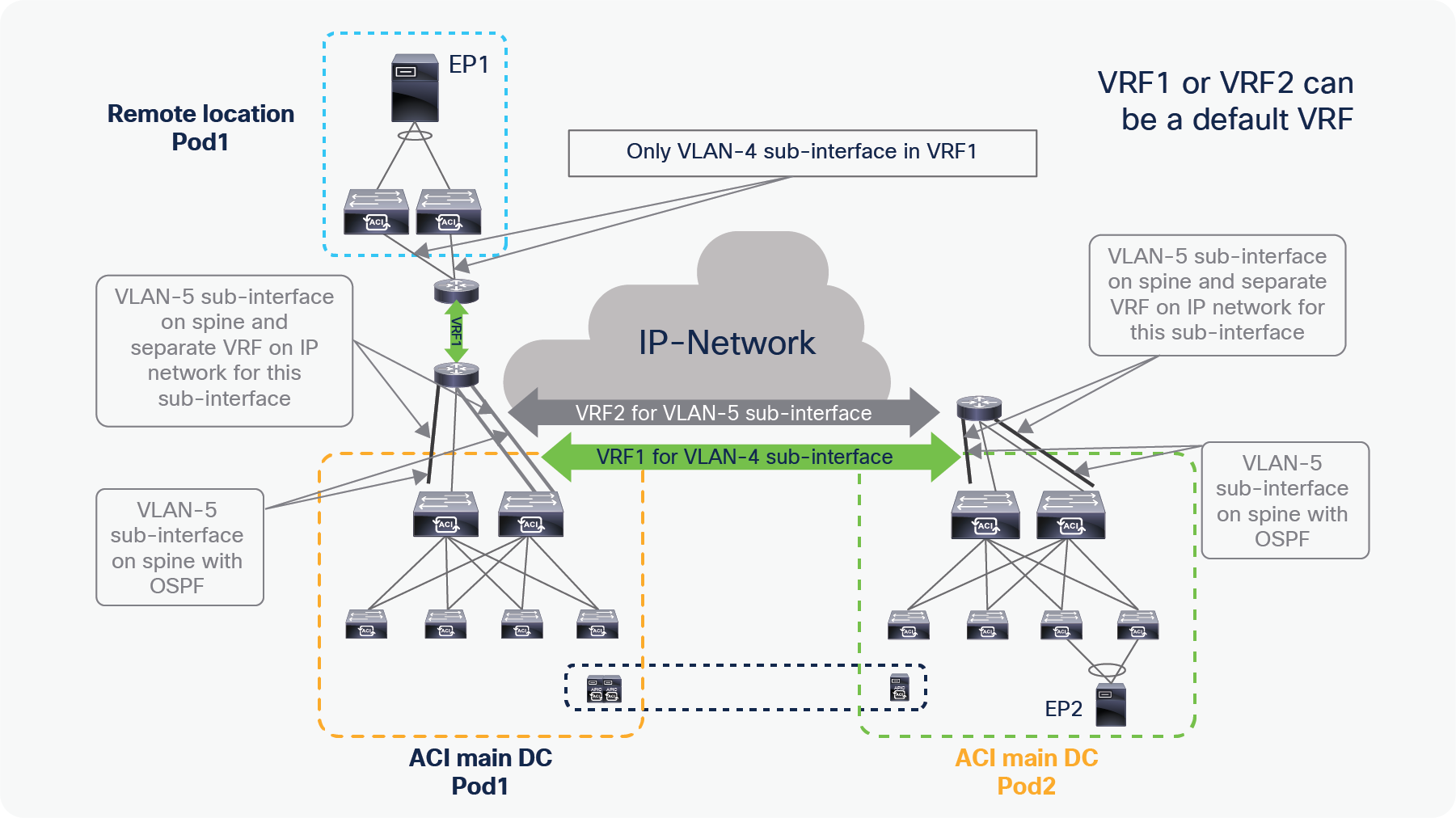
Solution for EP flaps with RL and Multi-Pod
The following figure highlights the configuration that is needed for supporting the integration of remote leaf nodes with an ACI Multi-Pod fabric to ensure that unicast and multicast traffic flows take the same path, avoiding flapping of EP information. It is critical to highlight that this configuration is not required without Multi-Pod.
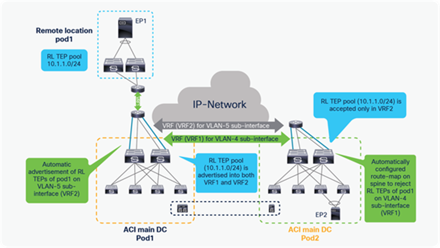
Configuration details for RL and Multi-Pod
● As part of the regular ACI Multi-Pod configuration, an L3Out in the infra tenant is required, leveraging VLAN-4 sub-interfaces on the spines to peer via OSPF with the IPN routers. For integrating remote leaf nodes with a Multi-Pod fabric, it is additionally required to create a separate L3Out in the infra tenant leveraging VLAN-5 sub-interfaces (with OSPF enabled as well).
● The corresponding VLAN-5 sub-interfaces on the upstream IPN routers are configured in a different routing domain (VRF2) than the one used by VLAN-4 sub-interfaces (VRF1) for east-west Multi-Pod traffic. Notice that either of the two VRFs can be represented in the global routing table of the IPN device, if desired.
● The IPN must extend connectivity across Pods for this second VRF (VRF2) to which VLAN-5 sub-interfaces are connected. This can be achieved in multiple ways, such as MPLS VPN, VXLAN, or VRF-lite.
● The remote leaf nodes remain configured with only VLAN-4 sub-interfaces used to peer OSPF with the IPN. VLAN-4 sub-interfaces on upstream routers are configured in the VRF (VRF1). As a consequence, reachability information for the RL TEP pool is propagated across the IPN only in the context of VRF1.
● In addition, the APIC controller automatically applies the configuration shown in the figure below and required to implement the following key functionalities:

Automatic configuration done by APIC for RL and Multi-Pod
● Spines that are part of the Pod to which the RL nodes are logically associated start advertising the RL TEP pool on VLAN-5 sub-interfaces to all other Pods.
● Spines are configured with a route-map to reject learning of that remote leaf TEP pool of all other Pods on VLAN-4 sub-interfaces. Spines accept only their associated RL’s TEP pools on VLAN-4 sub-interfaces.
As a result of those two automatic configuration steps, all the spines that are part of the remote Pods have reachability information toward the RL TEP Pool (10.1.1.0/24) only via the second set of sub-interfaces (leveraging VLAN tag 5) and in the context of the second VRF (VRF2) inside the IP Network.
Let’s take a look at how the unicast traffic from Multi-Pod local leaf to remote leaf changes after applying this configuration.
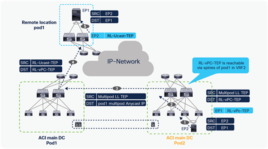
Unicast traffic from Multi-Pod local leaves to remote leaves
● EP2 sends a unicast packet to EP1 with the source MAC address of EP2 and the destination MAC address of EP1.
● The Multi-Pod leaf receives this packet and performs a Layer 2 lookup of EP1 in its hardware table and finds the next-hop as the anycast IP address of the remote leaf (RL-vPC-TEP). The leaf switch encapsulates the packet in the VXLAN header with the source TEP as its own TEP (Multi-Pod LL TEP) and the destination as RL-vPC-TEP.
● The packet is received on one of the spines of Pod2, which has reachability information for RL-vPC-TEP via VLAN-5 sub-interfaces that are part of VRF2 in the IPN. The spines in Pod2 do not have direct reachability to the remote leaf in the context of VRF2; therefore, the packet must first be routed toward the spines in Pod1. The spines in Pod2 change the destination TEP to the anycast IP address of the spines in Pod1 for Multi-Pod purposes.
● One of the spines in Pod1 receives the packet and changes the source TEP to the anycast IP address of the spine (RL-Ucast-TEP) and the destination to RL-vPC-TEP.
● One of the remote leaf switches receives the packet and updates the EP2 information in its local hardware table with a next-hop of RL-Ucast-TEP, learned from the source TEP of the VXLAN- encapsulated packet. This behavior is now the same as the L2 multicast traffic previously described.
Now traffic path is same for both Unicast and Multicast traffic from Multi-Pod local leaf to remote leaf, hence there is no EP information flap on remote leaf.