The documentation set for this product strives to use bias-free language. For the purposes of this documentation set, bias-free is defined as language that does not imply discrimination based on age, disability, gender, racial identity, ethnic identity, sexual orientation, socioeconomic status, and intersectionality. Exceptions may be present in the documentation due to language that is hardcoded in the user interfaces of the product software, language used based on RFP documentation, or language that is used by a referenced third-party product. Learn more about how Cisco is using Inclusive Language.
When configuring your Cisco ACI Multi-Site environment, keep in mind that the following ports are used by the Cisco ACI Multi-Site Orchestrator for network communications within the Cisco ACI Multi-Site environment.
Ports required for network communications between the Cisco ACI Multi-Site Orchestrator and Cisco APICs (Sites):
TCP Port 80/443 for APIC REST Configuration Deployment
Ports required for network communications between the Cisco ACI Multi-Site Orchestrator nodes:
TCP port 2377 for Cluster Management Communications
TCP and UDP port 7946 for Inter-Manager Communication
UDP port 4789 for Docker Overlay Network Traffic
All control-plane and data-plane traffic between Cisco ACI Multi-Site Orchestrator nodes is encrypted with IPSec's Encapsulating Security Payload (ESP) using IP protocol number 50 to provide
security and allow the cluster deployments over a round-trip time distance of up to 150ms. If there is firewall between any
Orchestrator nodes, proper rules must be added to allow this traffic.
Defining the Overlay TEP for Cisco APIC Sites Using the Cisco APIC GUI
Before connecting a Cisco APIC cluster (fabric) in a Cisco ACI Multi-Site topology, you must configure the Overlay Tunnel Endpoint (TEP) in the Fabric Ext Connection Policy for each fabric.
The Create Intrasite/Intersite Profile panel in the Cisco APIC GUI is used to add connection details for Cisco APIC multipod, remote leaf switches connecting to the Cisco ACI fabric, and APIC sites managed by Cisco ACI Multi-Site Orchestrator. When the Cisco ACI Multi-Site infrastructure has been configured, the Cisco ACI Multi-Site Orchestrator adds the Intersite Overlay TEP to this Cisco APIC policy.
To configure the Overlay TEP in the Fabric Ext Connection Policy for each Cisco APIC site to be managed by Cisco ACI Multi-Site Orchestrator, perform the following steps:
Procedure
Step 1
On the menu bar, click Tenants > infra.
Step 2
On the navigation pane (prior to Cisco APIC, Release 3.1), expand Networking and Protocol Policies.
Step 3
On the navigation pane (in APIC, Release 3.1 and later), expand Policies and Protocol.
Step 4
Right-click Fabric Ext Connection Policies and choose Create Intrasite/Intersite Profile.
Step 5
Click the + symbol on Pod Connection Profile.
Step 6
Choose the Pod ID from the list.
Step 7
Enter the IP address for overlay traffic to this pod.
Step 8
Click Update and Submit.
Configuring Infra Prerequisites and Guidelines
The following sections describe the steps necessary to configure the general as well as site-specific fabric Infra settings.
Before you proceed with Infra configuration, you must have configured and added the sites as described in previous sections,
which includes:
Configuring each site's fabric access policies.
Configuring direct communication and routable subnets for sites with remote leaf
switches.
In addition, keep in mind the following:
Any infrastructure changes such as adding and removing spine switches or spine node ID changes require a Multi-Site fabric connectivity information refresh.
The Overlay Unicast TEP, Overlay Multicast TEP, and BGP-EVPN Router-IDs IP
addresses assigned on the Orchestrator should not be taken from the address
space of the original fabric's Infra TEP pool or from the
0.x.x.x range.
Configuring Infra Using Cisco ACI Multi-Site Orchestrator GUI
This section describes how to register sites and configure fabric connectivity infra for the sites using the Cisco ACI Multi-Site Orchestrator GUI.
In Cisco APIC, you need to have one POD profile and it must contains a POD policy group. If it does not have a POD policy group you need
to create one.
To check if the POD profile contains a POD policy group:
Navigate to the Cisco APIC GUI, Fabric > Fabric Policies > Pod Policies > Profiles > Pod Profile default.
To create a POD policy group:
Navigate to the Cisco APIC GUI, Fabric > Fabric Policies > Pod Policies, right-click Policy Groups and click Create Pod Policy Group. Enter the appropriate information and click Submit.
To assign the new pod policy group to the POD Profile default:
Navigate to the Cisco APIC GUI, Fabric > Fabric Policies > Pod Policies > Profiles > Pod Profile default. Click on the default, choose the new pod policy group and click Update.
Any infrastructure changes such as adding, removing spines or spine node ID changes would require a Multi-Site fabric connectivity site refresh.
Procedure
Step 1
Log in to the Cisco ACI Multi-Site Orchestrator GUI, in the Main menu, click Sites.
Step 2
In the Sites List area, click CONFIGURE INFRA.
Step 3
In the Fabric Connectivity Infra page, perform the following actions:
In the Master List, click General Settings.
In the Canvas, in the BGP PEERING TYPE area, from the drop-down list, choose either full-mesh or route-reflector.
The default is full-mesh.
In the KEEPALIVE INTERVAL (SECONDS) field, enter the keep alive interval seconds.
The default is 60 seconds.
In the HOLD INTERVAL (SECONDS) field, enter the hold interval seconds.
The default is 180 seconds.
In the STALE INTERVAL (SECONDS) field, enter stale interval seconds.
The default is 300 seconds.
In the GRACEFUL HELPER field, choose ON or OFF.
The default is ON.
In the MAXIMUM AS LIMIT field, enter the maximum as limit.
The default is 0.
In the BGP TTL BETWEEN PEERS field, enter the BGP TTL between peers.
The default is 10.
Step 4
In the Property Pane, in the OSPF area, perform the following actions:
You can either modify the msc-ospf-policy-default policy or you can add a new OSPF policy.
To add a new OSPF, click ADD POLICY.
In the POLICY NAME field, enter the policy name.
In the NETWORK POINT field, choose either broadcast, point-to-point, or unspecified.
The default is broadcast.
In the PRIORITY field, enter the priority number.
The default is 1.
In the COST OF INTERFACE field, enter the cost of interface.
The default is 0.
In the INTERFACE CONTROLS field, choose advertise-subnet, bfd, mtu-ignore, or passive-participation.
In the HELLO INTERVAL (SECONDS) field, enter the hello interval in seconds.
The default is 10.
In the DEAD INTERVAL (SECONDS) field, enter the dead interval in seconds.
The default is 40.
In the RETRANSMIT INTERVAL (SECONDS) field, enter the retransmit interval in seconds.
The default is 5.
In the TRANSMIT DELAY (SECONDS) field, enter the transmit delay in seconds.
The default is 1.
Step 5
In the Master list, choose a site from the SITE SETTINGS.
In the Property Pane, perform the following actions:
Note
If you add or remove any spines in the Cisco APIC GUI, in the Canvas, click on the site and click refresh. This will discover any new or removed spines and all site-related fabric connectivity
to be re-imported from Cisco APIC. Any changes not pushed to Cisco APIC will be lost.
In the SITE IS MULTI-SITE ENABLED, turn on the site.
In the APIC SITE ID field, only displays the Cisco APIC site ID. You cannot change the site ID.
In the OVERLAY MULTICAST TEP field, enter the Overlay multicast TEP IP address.
In the BGP AUTONOMOUS SYSTEM NUMBER field, enter the BGP autonomous system number or the IP address.
(Optional) In the BGP PASSWORD field, if you have encryption enable then you can set a BGP password.
If you are running release 1.1(2) or prior: In the BGP COMMUNITY field, enter the BGP community. The format example is: extended:as2-nn4:4:15. The numbers are variables.
In the OSPF AREA ID field, enter the OSPF area ID or the IP address.
Note
When configuring the Multi-Site infra OSPF details, Cisco recommends that you use OSPF Area 0. If you use an Area ID other than 0, in the next step configure it as a regular OSPF area type and not a stub area type.
In the OSPF AREA TYPE field, choose either nssa, regular, or stub.
The default is nssa.
In the EXTERNAL ROUTER DOMAIN field, choose a external router domain that you have created in the APIC GUI.
In the IP SUBNETS TO IMPORT field, click ADD SUBNET. You can have more than one subnet.
In the SUBNET field, enter the subnet. You can either add the IP address or the IP address/netmask.
Click SAVE.
In the Cavans, click on the POD and perform the following actions:
In the Property Pane, in the OVERLAY UNICAST TEP field, enter the Overlay unicast TEP IP address.
In the Cavans, click on the spine and perform the following actions:
In the Property Pane, click ADD PORT and perform the following actions:
In the PORT ID field, enter the port ID (1/29).
In the IP ADDRESS field, enter the IP address/netmask.
In the MTU field, enter the MTU. The range is 576 to 9000 or inherit.
In the OSPF POLICY field, choose the OSPF policy.
Click SAVE.
Note
Cisco ACI Multi-Site Orchestrator creates a sub-interface with VLAN 4 with the specified IP ADDRESS under the specified PORT.
MTU of the spine port should match MTU on IPN side.
OSPF settings under OSPF policy should match on IPN side.
Multi-Site does not require to run PIM Bidir inside the IPN.
(Optional) In the Property Pane, turn on BGP PEERING.
In the BGP-EVPN Router-ID field, enter the BGP-EVPN Router-ID IP address.
(Optional) In the SPINE IS ROUTE REFLECTOR field, turn it on if the spine can be route reflected.
Repeat step 5c for each spine.
Repeat step 5 for the other sites.
Step 6
(Optional) If you are running release 1.2(1) or later and decide to use the same Overlay Unicast TEP for Cisco ACI Multi-Site.
In the Fabric Connectivity Infra, click on the site.
Click on the POD.
In the Property Pane, you can add the same Overlay Unicast TEP for each POD.
For more information, in the Overlay Unicast TEP field, click on the i icon.
Step 7
Click APPLY.
Note
If you receive an error message regarding a value that is incorrect in the a field for a particular site, go to that site
and correct the value. Then click APPLY.
Adding Sites Using Multi-Site Orchestrator GUI
This section describes how to add sites using the Cisco ACI Multi-Site Orchestrator GUI.
Procedure
Step 1
Log in to the Multi-Site GUI, in the Main menu, click Sites.
If you are logging in for the first time, the default log in is admin and password is We1come2msc!. Then you are forced to change the password upon initial log in.
The new password requirements are:
At least 12 characters
At least 1 letter
At least 1 number
At least 1 special character apart from * and space
Step 2
In the Sites List page, click ADD SITES.
Step 3
In the Sites Details page, perform the following actions:
In the NAME field, enter the site name.
In the LABELS field, choose or create a label.
In the APIC CONTROLLER URL field, enter the Cisco APIC URL. This can be https://<ip_address/dns_registered_hostname> or http://<ip_address/dns_registered_hostname>.
If you have more than one APIC in a fabric, click the + icon to add additional APICs.
In the USERNAME field, enter the user name.
In the PASSWORD field, enter the password.
You can turn on the SPECIFY DOMAIN FOR SITE switch, if you want to specify a domain name for the site.
In the DOMAIN NAME field, enter the domain name for the site.
If the Cisco APIC site does not have a site ID, you will receive the following message:
Cisco APIC does not have an apic-site-id configured. Please provide a unique apic-site-id for this site. Once specified the apic-site-id cannot be changed without factory resetting Cisco APIC.
Click Ok.
In the SITE ID field, enter the site ID.
The site ID must be an unique identifier of the Cisco APIC site. The range must be from 1 to 127.
Click SAVE.
Step 4
Repeat these steps to add additional sites.
Deleting Sites Using Multi-Site Orchestrator GUI
This section describes how to delete sites using the Multi-Site GUI.
Procedure
Step 1
Log in to the Multi-Site GUI.
Step 2
Ensure you unbind the site from any Schema’s before trying to delete the site.
Step 3
In the Main menu, click Sites.
Step 4
In the Sites List page, hover over the site you want to delete and choose Action > Delete .
Step 5
Click YES.
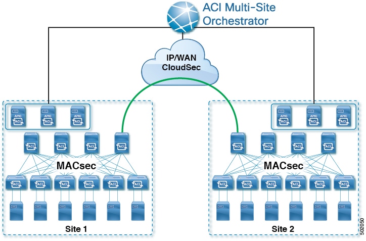
Cisco ACI CloudSec Encryption
As most Cisco ACI deployments are adopting the Cisco ACI Multi-Site architecture to address disaster recovery and scale, the current security implementation using MACsec encryption within local
site is becoming insufficient to guarantee data security and integrity across multiple sites connected by insecure external
IP networks interconnecting separate fabrics. Cisco ACI Multi-Site Orchestrator Release 2.0(1) introduces the CloudSec Encryption feature designed to provide inter-site encryption of traffic.
Cisco ACI Multi-Site topology uses three tunnel end-point (TEP) IP addresses to provide connectivity between sites. These TEP addresses are configured
by the admin on Cisco ACI Multi-Site Orchestrator and pushed down to each site's Cisco APIC, which in turn configures them on the spine switches. These three addresses are used to determine when traffic is destined
for a remote site, in which case an encrypted CloudSec tunnel is created between the two spine switches that provide physical
connectivity between the two sites through the Inter-Site Network (ISN).
The following figure illustrates the overall encryption approach that combines MACsec for local site traffic and CloudSec
for inter-site traffic encryption.
Figure 1. CloudSec Encryption
Hardware Requirement
The current release supports CloudSec Encryption on the following hardware::
Cisco Nexus 9364 and 9332 spine switches
FX line cards in Cisco Nexus 9500 switches
CloudSec Encryption Terminology
CloudSec Encryption feature provides a secure upstream symmetric key allocation and distribution method for initial key and
rekey requirements between sites. The following terminology is used in this chapter:
Upstream device – The device that adds the CloudSec Encryption header and does the encryption of the VxLAN packet payload on transmission
to a remote site using a locally generated symmetric cryptography key.
Downstream device – The device that interprets the CloudSec Encryption header and does the decryption of the VxLAN packet payload on reception
using the cryptography key generated by the remote site.
Upstream site – The datacenter fabric that originates the encrypted VxLAN packets.
Downstream site – The datacenter fabric that receives the encrypted packets and decrypts them.
TX Key – The cryptography key used to encrypt the clear VxLAN packet payload. In ACI only one TX key can be active per remote site.
RX Key – The cryptography key used to decrypt the encrypted VxLAN packet payload. In ACI two RX key can be active per remote site.
Symmetric Keys – When the same cryptography key is used to encrypt (TX Key) and decrypt (RX Key) a packet stream by the upstream and downstream devices respectively.
Rekey – The process initiated by the upstream site to replace its old key with a newer key for all downstream sites after the old
key expires.
Secure Channel Identifier (SCI) – A 64-bit identifier that represents a security association between the sites. It is transmitted in encrypted packet in
CloudSec header and is used to derive the RX key on the downstream device for packet decryption.
Association Number (AN) – A 2-bit number (0, 1, 2, 3) that is sent in the CloudSec header of the encrypted packet and is used to derive the key at the downstream device in conjunction
with the SCI for decryption. This allows multiple keys to be active at the downstream device to handle out of order packet
arrivals with different keys from the same upstream device following a rekey operation.
In ACI only two association number values (0 and 1) are used for the two active RX keys and only one association number value (0 or 1) is used for the TX Key at any point in time.
Pre-shared key (PSK) – One ore more keys must be configured in the Cisco APIC GUI to be used as a random seed for generating the CloudSec TX and RX keys. If multiple PSK are configured, each rekey process
will use the next PSK in order of their indexes; if no higher index PSK is available, a PSK with the lowest index will be
used. Each PSK must be a hexadecimal string 64 characters long. Cisco APIC supports up to 256 pre-shared keys.
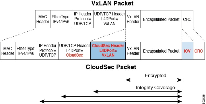
CloudSec Encryption and Decryption Handling
In order to provide a fully integrated, simple, and cost-effective solution that addresses both, data security and integrity,
starting with Release 2.0(1), Cisco ACI Multi-Site provides a CloudSec Encryption feature that allows for complete source-to-destination packet encryption between Multi-Site fabrics.
The following figure shows packet diagram before and after CloudSec encapsulation, followed by descriptions of the encryption
and decryption processes:
Figure 2. CloudSec Packet
Packet Encryption
The following is a high level overview of how CloudSec handles outgoing traffic packets:
The packets are filtered using the outer IP header and Layer-4 destination port information and matching packets are marked
for encryption.
The offset to use for encryption is calculated according to the fields of the packet. For example, the offset may vary based
on whether there is a 802.1q VLAN or if the packet is an IPv4 or IPv6 packet.
The encryption keys are programmed in the hardware tables and are looked up from the table using the packet IP header.
Once the packet is marked for encryption, the encryption key is loaded, and the offset from the beginning of the packet where
to start the encryption is known, the following additional steps are taken:
The UDP destination port number is copied from the UDP header into a CloudSec field for recovery when the packet is decrypted.
The UDP destination port number is overwritten with a Cisco proprietary Layer-4 port number (Port 9999) indicating that it is a CloudSec packet.
The UDP length field is updated to reflect the additional bytes that are being added.
The CloudSec header is inserted directly after the UDP header.
The Integrity Check Value (ICV) is inserted at the end of the packet, between the payload and the CRC.
The ICV requires construction of a 128-bit initialization vector. For CloudSec, any use of the source MAC address for ICV
purposes is replaced by a programmable value per SCI.
CRC is updated to reflect the change in the contents of the packet.
Packet Decryption
The way CloudSec handles incoming packets is symmetric to the outgoing packets algorithm described above:
If the received packet is a CloudSec packet, it is decrypted and the ICV is verified.
If ICV verification passed, the extra fields are removed, the UDP destination port number is moved from the CloudSec header
to the UDP header, the CRC is updated, and the packet is forwarded to destination after decryption and CloudSec header removal.
Otherwise the packet is dropped.
If the key store returns two or more possible decryption keys, the Association Number (AN) field of the CloudSec header is
used to select which key to use.
If the packet is not a CloudSec packet, the packet is left unchanged.
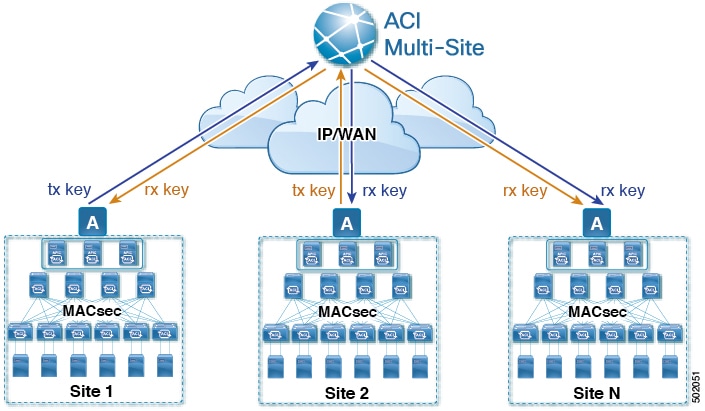
CloudSec Encryption Key Allocation and Distribution
Initial Key Configuration
Figure 3. CloudSec Key Distribution
The following is a high level overview of the CloudSec encryption key initial allocation and distribution process illustrated
by the figure above:
The upstream site's Cisco APIC generates a local symmetric key intended to be used for data encryption of VxLAN packets transmitted from its site. The same
key that is used by the upstream site for encryption is used for decryption of the packets on the downstream remote receiving
sites.
Every site is an upstream site for the traffic it transmits to other sites. If multiple sites exist, each site generates its
own site-to-site key and use that key for encryption before transmitting to the remote site.
The generated symmetric key is pushed to the Cisco ACI Multi-Site Orchestrator (MSO) by the upstream site's Cisco APIC for distribution to downstream remote sites.
The MSO acts as a message broker and collects the generated symmetric key from the upstream site's Cisco APIC, then distributes it to downstream remote sites' Cisco APICs.
Each downstream site's Cisco APIC configures the received key as RX key on the local spine switches which are intended to receive the traffic from the upstream
site that generated the key.
Each downstream site's Cisco APIC also collects the deployment status of the RX Key from the local spine switches and then pushes it to the MSO.
The MSO relays the key deployment status from all downstream remote sites back to the upstream site's Cisco APIC.
The upstream site's Cisco APIC checks if the key deployment status received from all downstream remote sites is successful.
If the deployment status received from a downstream device is successful, the upstream site deploys the local symmetric key
as its TX key on the spine switches to enable encryption of the VxLAN packets that are sent to the downstream site.
If the deployment status received from a downstream device is failed, a fault is raised on the Cisco APIC site where it failed and it is handled based on the "secure mode" setting configured on the MSO. In "must secure" mode the
packets are dropped and in the "should secure" mode the packets are sent clear (unencrypted) to the destination site.
Note
In current release, the mode is always set to “should secure”.
Rekey Process
Each generated TX/RX key expires after a set amount of time, by default key expiry time is set to 15 minutes. When the initial
set of TX/RX keys expires, a rekey process takes place.
The same general key allocation and distribution flow applies for the rekey process. The rekey process follows the "make before
break" rule, in other words all the RX keys on the downstream sites are deployed before the new TX key is deployed on the
upstream site. To achieve that, the upstream site will wait for the new RX key deployment status from the downstream sites
before it configures the new TX key on the local upstream site's devices.
If any downstream site reports a failure status in deploying the new RX key, the rekey process will be terminated and the
old key will remain active. The downstream sites will also keep the old and the new RX keys deployed after the new key deployment
is finished for some duration to ensure that out of order packet deliveries with either key can be properly decrypted.
In case of any downstream site failing to deploy the new encryption key generated by the rekey process, the new key is discarded
and the upstream device will continue to use the previous valid key as TX key. This approach keeps the upstream sites from
having to maintain multiple TX keys per set of downstream sites. However, this approach may also result in the rekey process
being delayed if the rekey deployment failures continue to occur with any one of the downstream sites. It is expected that
the Multi-Site administrator will take action to fix the issue of the key deployment failure for the rekey to succeed.
Cisco APIC's Role in Key Management
The Cisco APIC is responsible for key allocation (both, initial key and rekey distribution), collection of the key deployment status messages
from the spine switches, and notification of the Cisco ACI Multi-Site Orchestrator about each key's status for distribution to other sites.
Cisco ACI Multi-Site Orchestrator's Role in Key Management
The Cisco ACI Multi-Site Orchestrator is responsible for collecting the TX keys (both, initial key and subsequent rekeys) from the upstream site and
distributing it to all downstream sites for deployment as RX keys. The MSO also collects the RX key deployment status information
from the downstream sites and notifies the upstream site in order for it to update the TX key on successful RX key deployment
status.
Upstream Model
In contrast to other technologies, such as MPLS, that use downstream key allocation, CloudSec's upstream model provides the
following advantages:
The model is simple and operationally easier to deploy in the networks.
The model is preferred for Cisco ACI Multi-Site use cases.
It provides advantages for multicast traffic as it can use the same key and CloudSec header for each copy of the replicated
packet transmitted to multiple destination sites. In downstream model each copy would have to use a different security key
for each site during encryption.
It provides easier troubleshooting in case of failures and better traceability of packets from the source to destination consistently
for both, unicast and multicast replicated packets.
CloudSec Supported Hardware and Port Ranges
The following table provides the hardware platforms and the port ranges that are capable of CloudSec encryption:
Hardware Platform
Port Range
N9K-C9364C spine switches
Ports 49-64
N9K-C9332C spine switches
Ports 25-32
N9K-X9736C-FX line cards
Ports 29-36
If CloudSec is enabled for a site, but the encryption is not supported by the ports, a fault is raised with unsupported-interface error message.
You must configure one or more Pre-Shared Keys (PSK) to be used by the Cisco APIC for generating the CloudSec encryption and decryption keys. The PSK are used as a random seed during the re-key process.
If multiple PSK are configured, each re-key process will use the next PSK in order of their indexes; if no higher index PSK
is available, a PSK with the lowest index will be used.
Because PSK is used as a seed for encryption key generation, configuring multiple PSK provides additional security by lowering
the over-time vulnerability of the generated encryption keys.
Note
If no pre-shared key is configured on the Cisco APIC, CloudSec will not be enabled for that site. In that case, turning on CloudSec setting in Cisco ACI Multi-Site will raise a fault.
If at any time you wish to refresh a previously added PSK with a new one, simply repeat the procedure as if you were adding
a new key, but specify an existing index.
You can configure one or more pre-shared keys in one of three ways:
Configuring Cisco APIC for CloudSec Encryption Using GUI
This section describes how to configure one or more pre-shared keys (PSK) using the Cisco APIC GUI.
Procedure
Step 1
Log in to APIC.
Step 2
Navigate to Tenants > infra > Policies > CloudSec Encryption
Step 3
Specify the SA Key Expiry Time.
This option specifies how long each key is valid (in minutes). Each generated TX/RX key expires after the specified amount
of time triggering a re-key process. The expiration time can be between 5 and 1440 minutes.
Step 4
Click the + icon in the Pre-Shared Keys table.
Step 5
Specify the Index of the pre-shared key you are adding and then the Pre-Shared Key itself.
The Index field specifies the order in which the pre-shared keys are used. After the last (highest index) key is used, the process
will continue with the first (lowest index) key. Cisco APIC supports up to 256 pre-shared keys, so the PSK index value must be between 1 and 256.
Each Pre-Shared Key must be a hexadecimal string 64 characters long.
Configuring Cisco APIC for CloudSec Encryption Using NX-OS Style CLI
This section describes how to configure one or more pre-shared keys (PSK) using the Cisco APIC NX-OS Style CLI.
Procedure
Step 1
Log in to the Cisco APIC NX-OS style CLI.
Step 2
Enter configuration mode.
Example:
apic1# configure
apic1 (config)#
Step 3
Enter configuration mode for the default CloudSec profile.
Specify the Pre-Shared Keys (PSK) expiration time.
This option specifies how long each key is valid (in minutes). Each generated TX/RX key expires after the specified amount
of time triggering a re-key process. The expiration time can be between 5 and 1440 minutes.
Example:
apic1(config-cloudsec)# sakexpirytime<duration>
Step 5
Specify one or more Pre-Shared Keys.
In the following command, specify the index of the PSK you're configuring and the PSK string itself.
The <psk-index> parameter specifies the order in which the pre-shared keys are used. After the last (highest index) key is used, the process
will continue with the first (lowest index) key. Cisco APIC supports up to 256 pre-shared keys, so the PSK index value must be between 1 and 256.
The <psk-string> parameter specifies the actual PSK, which must be a hexadecimal string 64 characters long.
Step 6
(Optional) View the current PSK configuration.
You can view how many PSK are currently configured and their duration using the following command:
Example:
apic1(config-cloudsec)# show cloudsec summary
Configuring Cisco APIC for CloudSec Encryption Using REST API
This section describes how to configure one or more pre-shared keys (PSK) using the Cisco APIC REST API.
Procedure
Configure PSK expiration time, index, and string.
In the following XML POST, replace:
The value of sakExpiryTime with the expiration time of each PSK.
This sakExpiryTime parameter specifies how long each key is valid (in minutes). Each generated TX/RX key expires after the specified amount
of time triggering a re-key process. The expiration time can be between 5 and 1440 minutes.
The value of index with the index of the PSK you're configuring.
The index parameter specifies the order in which the pre-shared keys are used. After the last (highest index) key is used, the process
will continue with the first (lowest index) key. Cisco APIC supports up to 256 pre-shared keys, so the PSK index value must be between 1 and 256.
The value of pskString with the index of the PSK you're configuring.
The pskString parameter specifies the actual PSK, which must be a hexadecimal string 64 characters long.
Enabling CloudSec Encryption Using Cisco ACI Multi-Site Orchestrator GUI
The CloudSec encryption can be enabled or disabled for each site individually. However, the communications between two sites
will be encrypted only if the feature is enabled on both sites.
Before you begin
Before you enable the CloudSec encryption between two or more sites, you must have completed the following tasks:
From the left-hand sidebar, select the Sites view.
Step 3
Click on the Configure Infra button in the top right of the main window.
Step 4
From the left-hand sidebar, select the site for which you want to change the CloudSec configuration.
Step 5
In the right-hand sidebar, toggle the CloudSec Encryption setting to enable or disable the CloudSec Encryption feature for the site.
Rekey Process During Spine Switch Maintenance
The following is a summary of the CloudSec rekey process during typical maintenance scenarios for the spine switches where
the feature is enabled:
Normal Decommissioning – CloudSec rekey process stops automatically whenever a CloudSec-enabled spine switch is decommissioned. Rekey process will
not start again until the decommissioned node is commissioned back or the decommissioned node ID is removed from the Cisco APIC
Spine Switch Software Upgrade – CloudSec rekey process stops automatically if a spine switch is reloaded due to software upgrade. Rekey process will resume
after the spine switch comes out of reload.
Maintenance (GIR mode) – CloudSec rekey process must be manually stopped using the instructions provided in Disabling and Re-Enabling Re-Key Process Using NX-OS Style CLI. Rekey can be enabled back only after the node is ready to forward traffic again.
Decommissioning and Removal from Cisco APIC – CloudSec rekey process must be manually stopped using the instructions provided in Disabling and Re-Enabling Re-Key Process Using NX-OS Style CLI. Rekey can be enabled back only after the node is removed from Cisco APIC.
Disabling and Re-Enabling Re-Key Process Using NX-OS Style CLI
It is possible to manually stop and restart the re-key process. You may be required to manually control the re-key process
in certain situations, such as switch decommissioning and maintenance. This section describes how to toggle the setting using
Cisco APIC NX-OS Style CLI.
Procedure
Step 1
Log in to the Cisco APIC NX-OS style CLI.
Step 2
Enter configuration mode.
Example:
apic1# configure
apic1(config)#
Step 3
Enter configuration mode for the default CloudSec profile.
Disabling and Re-Enabling Re-Key Process Using REST API
It is possible to manually stop and restart the re-key process. You may be required to manually control the re-key process
in certain situations, such as switch decommissioning and maintenance. This section describes how to toggle the setting using
Cisco APIC REST API.
Procedure
Step 1
You can disable the rekey process using the following XML message.
Multi-Site currently supports the basic parameters to choose when creating a Tenant and setting up a site. Multi-Site supports most of the Tenant policies, but in addition to that you can configure some advanced parameters.
Use the Multi-Site GUI to manage the basic properties to configure. If you want to configure advanced properties, the capability to cross launch
into Cisco APIC GUI directly from the Multi-Site GUI is provided. You can also configure the additional properties directly in Cisco APIC.
There are three different access points in Multi-Site GUI from where you can cross launch into APIC. From these access points in Multi-Site, you can open a new browser tab with access into Cisco APIC. You will log in to Cisco APIC at that point for the first time, and the associated screen is displayed in the Cisco APIC GUI.
Cross-Launch to Cisco APIC from Sites
Before you begin
At least one site must be configured in Multi-Site.
The site must contain at least one tenant with entities such as VRF and bridge domain configured.
Procedure
Step 1
From the left-hand sidebar, open the Sites view.
Step 2
From the Sites list, hover over the name of the appropriate site, click the Actions icon at the end of the row, and choose Open in APIC User Interface to access the Cisco APIC GUI.
The APIC GUI login screen is displayed for logging in with APIC GUI credentials.
Cross-Launch to Cisco APIC from Schemas
Before you begin
At least one site based on a template must be configured in Multi-Site.
The site must contain at least one tenant with entities such as VRF and bridge domain configured.
Procedure
Step 1
From the left-hand sidebar, open the Schemas view.
Step 2
From the Schemas list, click the appropriate <schema-name>.
Step 3
From the left-hand sidebar Sites list, hover over the name of the appropriate site, click the Actions icon at the end of the row, and choose Open in APIC User Interface to access the Cisco APIC GUI.
The APIC GUI login screen is displayed for logging in with APIC GUI credentials.
Cross-Launch to Cisco APIC from the Property Pane
Before you begin
At least one site must be configured in Multi-Site.
The site must contain at least one tenant with entities such as VRF and bridge domain configured.
Procedure
Step 1
From the left-hand sidebar, open the Schemas view.
Step 2
From the Schemas list, click the appropriate <schema-name>.
Step 3
From the left-hand sidebar Sites list, choose the appropriate site.
Step 4
In the Canvas, choose the name of a specific entity.
For example, choose an available VRF, Contract, Bridge Domain, or another entity as appropriate.
The details for the specific entity are displayed in the Property Pane on the right.
Step 5
In the top right of the Property Pane, click the Open in APIC User Interface icon to access the Cisco APIC GUI.
The APIC GUI login screen is displayed for logging in with APIC GUI credentials.
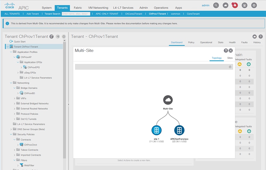
Viewing Cisco ACI Multi-Site-Managed Objects Using the Cisco APIC GUI
When an APIC cluster is managed by Multi-Site, cloud icons indicate the relationships with other sites.
Figure 4. Viewing Multi-Site-Managed Objects Using the APIC GUI
Before you begin
The APIC cluster/site must be set up to be managed by Cisco ACI Multi-Site.
Procedure
Step 1
To view the relationship of the APIC site with other sites, click the cloud icon at the upper right, next to the settings icons.
In the diagram, hover over the light blue site icon to see the local site details, and hover over the dark blue icon to see
the remote site details.
In the image, T1 and its Application Profile, EPG, BD, VRF, and contracts are marked with cloud icons. This indicates that
they are managed by Multi-Site. We recommend that you only make changes to these objects in the Multi-Site GUI.
Step 2
To view the localized or stretched usage of a VRF, bridge domain, or other objects, where there is a Show Usage button on the information page, perform the following steps; for example for Bridge Domain and VRF:
On the menu bar, click Tenants and double-click on a tenant that is managed by Multi-Site.
Here you can view the nodes or policies using the object.
Note
It is recommended to make changes to managed policies only in the Multi-Site GUI.
Step 4
To set the scope of deployment notification settings for this BD or VRF, click Change Deployment Settings. You can enable warnings to be sent for all deletions and modifications of the object on the Policy tab.
Step 5
To enable or disable Global warnings, check or uncheck the (Global) Show Deployment Warning on Delete/Modify check box.
Step 6
To enable or disable Local warnings, choose Yes or No on the (Local) Show Deployment Warning on Delete/Modify field.
Step 7
To view any past warnings, click the History tab Events or Audit Logs.

 Feedback