-
Cisco MDS 9000 Family Configuration Guide, Release 2.x
-
New and Changed Information
-
Index
-
Preface
- Part 1 - Getting Started
- Part 2 - Cisco MDS SAN-OS Installation and Switch Management
- Part 3 - Switch Configuration
-
Part 4 - Fabric Configuration
-
Configuring and Managing VSANs
-
Creating Dynamic VSANs
-
Configuring Inter-VSAN Routing
-
Configuring Zones
-
Distributing Device Alias Services
-
Configuring Fibre Channel Routing Services and Protocols
-
Managing FLOGI, Name Server, FDMI, and RSCN Databases
-
Discovering SCSI Targets
-
Configuring FICON
-
Advanced Features and Concepts
-
- Part 5 - Security
- Part 6 - IP Services
- Part 7 - Intelligent Storage Services
- Part 8 - Network and Switch Monitoring
- Part 9 - Traffic Management
- Part 10 - Troubleshooting
-
 Feedback
Table Of Contents
Configuring and Managing Zones
Active and Full Zone Set Considerations
Enabling Full Zone Set Distribution
Recovering from Link Isolation
Importing and Exporting Zone Sets
Configuring Default Zone QoS Priority Attributes
Assigning LUNs to Storage Subsystems
Read-Only Zone Configuration Guidelines
Renaming Zones, Zone Sets, fcaliases, and Zone Attribute Groups
Cloning Zones, Zone Sets, fcaliases, and Zone Attribute Groups
Changing from Basic Zoning to Enhanced Zoning
Changing from Enhanced Zoning to Basic Zoning
Displaying Enhanced Zone Information
Configuring and Managing Zones
Zoning enables you to set up access control between storage devices or user groups. If you have administrator privileges in your fabric, you can create zones to increase network security and to prevent data loss or corruption. Zoning is enforced by examining the source-destination ID field.
Advanced zoning capabilities specified in the FC-GS-4 and FC-SW-3 standards are provided. You can use either the existing basic zoning capabilities or the advanced, standards-compliant zoning capabilities.
This chapter includes the following sections:
•
Recovering from Link Isolation
•
•
•
Note
Zoning Features
Zoning has the following features:
•
–
–
–
–
–
•
–
–
–
•
–
–
•
•
–
–
–
–
–
–
–
•
•
Zoning Example
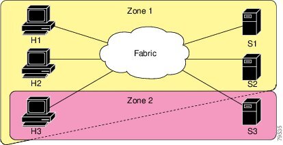
Figure 19-1 illustrates a zone set with two zones, zone 1 and zone 2, in a fabric. Zone 1 provides access from all three hosts (H1, H2, H3) to the data residing on storage systems S1 and S2. Zone 2 restricts the data on S3 to access only by H3. Note that H3 resides in both zones.
Figure 19-1 Fabric with Two Zones
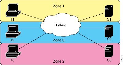
Of course, there are other ways to partition this fabric into zones. Figure 19-2 illustrates another possibility. Assume that there is a need to isolate storage system S2 for the purpose of testing new software. To achieve this, zone 3 is configured, which contains only host H2 and storage S2. You can restrict access to just H2 and S2 in zone 3, and to H1 and S1 in zone 1.
Figure 19-2 Fabric with Three Zones
Zone Implementation
All switches in the Cisco MDS 9000 Family automatically support the following basic zone features (no additional configuration is required):
•
•
•
•
•
•
•
•
•
•
•
If required, you can additionally configure the following zone features:
•
•
•
•
Zone Configuration
A zone can be configured using one of the following identifiers to assign members:
•
Caution
•
•
•
•
•
•
Configuring a Zone
To configure a zone and assign a zone name, follow these steps:
Tip
Note
Alias Configuration
You can assign an alias name and configure an alias member using either the FC ID, fabric port WWN (fWWN), or pWWN values.
Tip
To create an alias, follow these steps:
Zone Set Creation
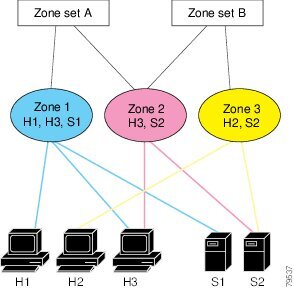
In Figure 19-3, two separate sets are created, each with its own membership hierarchy and zone members.
Figure 19-3 Hierarchy of Zone Sets, Zones, and Zone Members
Zones provide a mechanism for specifying access control, while zone sets are a grouping of zones to enforce access control in the fabric. Either zone set A or zone set B can be activated (but not together).
Tip
To create a zone set to include several zones, follow these steps:
Active and Full Zone Set Considerations
Before configuring a zone set, consider the following guidelines:
•
•
•
•
•
•
•
•
Note
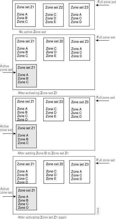
Figure 19-4 shows a zone being added to an activated zone set.
Figure 19-4 Active and Full Zone Sets
Activating a Zone Set
Changes to a zone set do not take effect to a full zone set until you activate it.
To activate a zone set, follow these steps:
Tip
Caution
Caution
Zone Enforcement
Zoning can be enforced in two ways: soft and hard. Each end device (N port or NL port) discovers other devices in the fabric by querying the name server. When a device logs in to the name server, the name server returns the list of other devices that can be accessed by the querying device. If an Nx port does not know about the FC IDs of other devices outside its zone, it cannot access those devices.
In soft zoning, zoning restrictions are applied only during interaction between the name server and the end device. If an end device somehow knows the FC ID of a device outside its zone, it can access that device.
Hard zoning is enforced by the hardware on each frame sent by an Nx port. As frames enter the switch, source-destination IDs are compared with permitted combinations to allow the frame at wirespeed. Hard zoning is applied to all forms of zoning.
Note
Switches in the Cisco MDS 9000 Family support both hard and soft zoning.
The Default Zone
Each member of a fabric (in effect a device attached to an Nx port) can belong to any zone. If a member is not part of any active zone, it is considered to be part of the default zone. Therefore, if no zone set is active in the fabric, all devices are considered to be in the default zone. Even though a member can belong to multiple zones, a member that is part of the default zone cannot be part of any other zone. The switch determines whether a port is a member of the default zone when the attached port comes up.
Note
Traffic can either be permitted or denied among members of the default zone. This information is not distributed to all switches; it must be configured in each switch.
Note
Configure the default zone policy on each switch in the fabric. If you change the default zone policy on one switch in a fabric, be sure to change it on all the other switches in the fabric.
Note
The default zone members are explicitly listed when the default policy is configured as permit or when a zone set is active. When the default policy is configured as deny, the members of this zone are not explicitly enumerated when you issue the show zoneset active command.
To permit or deny traffic in the default zone, follow these steps:
Zone Set Distribution
You can distribute full zone sets using one of two methods: at the EXEC mode level or at the configuration mode level. Table 19-1 lists the differences.
Enabling Full Zone Set Distribution
All switches in the Cisco MDS 9000 Family distribute active zone sets when new E port links come up or when a new zone set is activated in a VSAN. The zone set distribution takes effect while sending merge requests to the adjacent switch or while activating a zone set.
To enable full zone set and active zone set distribution to all switches on a per VSAN basis, follow these steps:
Step 1
switch# config t
Enters configuration mode.
Step 2
switch(config)# zoneset distribute full vsan 33
Enables sending a full zone set along with an active zone set.
One-Time Distribution
You can perform a one-time distribution of inactive, unmodified zone sets throughout the fabric.
Use the zoneset distribute vsan vsan-id command in EXEC mode to perform this distribution.
switch# zoneset distribute vsan 2Zoneset distribution initiated. check zone statusThis command only distributes the full zone set information—it does not save the information to the startup configuration. You must explicitly issue the copy running start command to save the full zone set information to the startup configuration.
Note
Use the show zone status vsan vsan-id command to check the status of the one-time zone set distribution request.
switch# show zone status vsan 2VSAN: 3 default-zone: permit distribute: active only Interop: 100mode:basic merge-control:allow session:nonehard-zoning:enabledDefault zone:qos:low broadcast:disabled ronly:disabledFull Zoning Database :Zonesets:0 Zones:0 Aliases: 0Active Zoning Database :Name: nozoneset Zonesets:1 Zones:2Status: Zoneset distribution completed at 04:01:06 Aug 28 2004Recovering from Link Isolation
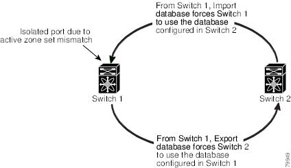
When two switches in a fabric are merged using a TE or E port, these TE and E ports may become isolated when the active zone set databases are different between the two switches or fabrics. When a TE port or an E port become isolated, you can recover that port from its isolated state using one of three options:
•
•
•
Figure 19-5 Importing and Exporting the Database
Importing and Exporting Zone Sets
To import or export the zone set information from or to an adjacent switch, follow these steps:
Note
Zone Set Duplication
You can make a copy and then edit it without altering the existing active zone set. You can copy an active zone set from the bootflash: directory, volatile: directory, or slot0, to one of the following areas:
•
•
The active zone set is not part of the full zone set. You cannot make changes to an existing zone set and activate it, if the full zone set is lost or is not propagated.
Caution
Copying Zone Sets
On the Cisco MDS Family switches, you cannot edit an active zone set. However, you can copy an active zone set to create a new zone set that you can edit.
To make a copy of a zone set, perform this step:
Caution
Zone Database Information
If required, you can clear configured information stored in the zone server database.
Note
Zone-Based Traffic Priority
The zoning feature provides an additional segregation mechanism to prioritize select zones in a fabric and set up access control between devices. Using this feature, you can configure the Quality of Service (QoS) priority as a zone attribute. You can assign the QoS traffic priority attribute to be high, medium, or low. By default, zones with no specified priority are implicitly assigned a low priority. See the "VSAN Versus Zone-Based QoS" section on page 47-6 for more information.
To use this feature, you need to obtain the ENTERPRISE_PKG license (see Chapter 3, "Obtaining and Installing Licenses") and you must enable QoS in the switch (see the "QoS Initiation for Data Traffic" section on page 47-7).
This feature allows SAN administrators to configure QoS in terms of a familiar data flow identification paradigm. You can configure this attribute on a zone-wide basis rather than between zone members.
Caution
To configure zone priority, follow these steps:
Configuring Default Zone QoS Priority Attributes
QoS priority attribute configuration changes take effect when you activate the zone set of the associated zone.
Note
To configure the QoS priority attributes for a default zone, follow these steps:
Configuring Broadcast Zoning
You can configure broadcast frames in the basic zoning mode. By default, broadcast zoning is disabled and broadcast frames are sent to all Nx ports in the VSAN. When enabled, broadcast frames are only sent to Nx ports in the same zone, or zones, as the sender. Enable broadcast zoning when a host or storage device uses this feature.
Tip
Caution
To broadcast frames in the basic zoning mode, follow these steps:
About LUN Zoning
Logical unit number (LUN) zoning is a feature specific to switches in the Cisco MDS 9000 Family.
Caution
A storage device can have multiple LUNs behind it. If the device port is part of a zone, a member of the zone can access any LUN in the device. With LUN zoning, you can restrict access to specific LUNs associated with a device.
Note
•
•
Note
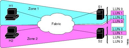
Figure 19-6 shows a LUN-based zone example.
Figure 19-6 LUN Zoning Access
Configuring a LUN-Based Zone
To configure a LUN-based zone, follow these steps:
Assigning LUNs to Storage Subsystems
LUN masking and mapping restricts server access to specific LUNs. If LUN masking is enabled on a storage subsystem and if you want to perform additional LUN zoning in a Cisco MDS 9000 Family switch, obtain the LUN number for each host bus adapter (HBA) from the storage subsystem and then configure the LUN-based zone procedure provided in the "Configuring a LUN-Based Zone" section.
Note
Caution
About Read-Only Zones
By default, an initiator has both read and write access to the target's media when they are members of the same Fibre Channel zone. The read-only zone feature allows members to have only read access to the media within a read-only Fibre Channel zone.
You can also configure LUN zones as read-only zones.
Read-Only Zone Configuration Guidelines
Any zone can be identified as a read-only zone. By default all zones have read-write permission unless explicitly configured as a read-only zone.
Follow these guidelines when configuring read-only zones:
•
•
•
•
The read-only zone feature behaves as designed if FAT16 or FAT32 file system is used with the previously-mentioned Windows operating systems.
Configuring Read-Only Zones
To configure read-only zones, follow these steps:
To configure the read-only option for a default zone, follow these steps:
Renaming Zones, Zone Sets, fcaliases, and Zone Attribute Groups
To rename a zone, zone set, fcalias, or zone-attribute-group, follow these steps:
Cloning Zones, Zone Sets, fcaliases, and Zone Attribute Groups
As of Cisco MDS SAN-OS Release 2.1(1a), you can clone a zone, zone set, fcalias, or zone-attribute-group.
To clone a zone, zone set, fcalias, or zone-attribute-group, follow these steps:
Displaying Zone Information
You can view any zone information by using the show command. If you request information for a specific object (for example, a specific zone, zone set, VSAN, or alias, or keywords such as brief or active), only information for the specified object is displayed. If you do not request specific information, all available information is displayed. See Examples 19-1 to 19-15.
Example 19-1 Displays Zone Information for All VSANs
switch# show zonezone name Zone3 vsan 1pwwn 21:00:00:20:37:6f:db:ddpwwn 21:00:00:20:37:9c:48:e5zone name Zone2 vsan 2fwwn 20:41:00:05:30:00:2a:1efwwn 20:42:00:05:30:00:2a:1efwwn 20:43:00:05:30:00:2a:1ezone name Zone1 vsan 1pwwn 21:00:00:20:37:6f:db:ddpwwn 21:00:00:20:37:a6:be:2fpwwn 21:00:00:20:37:9c:48:e5fcalias Alias1zone name Techdocs vsan 3ip-address 10.15.0.0 255.255.255.0zone name Zone21 vsan 5pwwn 21:00:00:20:37:a6:be:35pwwn 21:00:00:20:37:a6:be:39fcid 0xe000effcid 0xe000e0symbolic-nodename iqn.testfwwn 20:1f:00:05:30:00:e5:c6fwwn 12:12:11:12:11:12:12:10interface fc1/5 swwn 20:00:00:05:30:00:2a:1eip-address 12.2.4.5 255.255.255.0fcalias name Alias1 vsan 1pwwn 21:00:00:20:37:a6:be:35zone name Zone2 vsan 11interface fc1/5 pwwn 20:4f:00:05:30:00:2a:1ezone name Zone22 vsan 6fcalias name Alias1 vsan 1pwwn 21:00:00:20:37:a6:be:35zone name Zone23 vsan 61pwwn 21:00:00:04:cf:fb:3e:7b lun 0000Example 19-2 Displays Zone Information for a Specific VSAN
switch# show zone vsan 1
zone name Zone3 vsan 1
pwwn 21:00:00:20:37:6f:db:ddpwwn 21:00:00:20:37:9c:48:e5zone name Zone2 vsan 1fwwn 20:4f:00:05:30:00:2a:1efwwn 20:50:00:05:30:00:2a:1efwwn 20:51:00:05:30:00:2a:1efwwn 20:52:00:05:30:00:2a:1efwwn 20:53:00:05:30:00:2a:1ezone name Zone1 vsan 1pwwn 21:00:00:20:37:6f:db:ddpwwn 21:00:00:20:37:a6:be:2fpwwn 21:00:00:20:37:9c:48:e5fcalias Alias1Use the show zoneset command to view the configured zone sets.
Example 19-3 Displays Configured Zone Set Information
switch# show zoneset vsan 1
zoneset name ZoneSet2 vsan 1
zone name Zone2 vsan 1fwwn 20:4e:00:05:30:00:2a:1efwwn 20:4f:00:05:30:00:2a:1efwwn 20:50:00:05:30:00:2a:1efwwn 20:51:00:05:30:00:2a:1efwwn 20:52:00:05:30:00:2a:1ezone name Zone1 vsan 1pwwn 21:00:00:20:37:6f:db:ddpwwn 21:00:00:20:37:a6:be:2fpwwn 21:00:00:20:37:9c:48:e5fcalias Alias1zoneset name ZoneSet1 vsan 1zone name Zone1 vsan 1pwwn 21:00:00:20:37:6f:db:ddpwwn 21:00:00:20:37:a6:be:2fpwwn 21:00:00:20:37:9c:48:e5fcalias Alias1Example 19-4 Displays Configured Zone Set Information for a Range of VSANs
switch# show zoneset vsan 2-3
zoneset name ZoneSet2 vsan 2
zone name Zone2 vsan 2fwwn 20:52:00:05:30:00:2a:1efwwn 20:53:00:05:30:00:2a:1efwwn 20:54:00:05:30:00:2a:1efwwn 20:55:00:05:30:00:2a:1efwwn 20:56:00:05:30:00:2a:1ezone name Zone1 vsan 2pwwn 21:00:00:20:37:6f:db:ddpwwn 21:00:00:20:37:a6:be:2fpwwn 21:00:00:20:37:9c:48:e5fcalias Alias1zoneset name ZoneSet3 vsan 3zone name Zone1 vsan 1pwwn 21:00:00:20:37:6f:db:ddpwwn 21:00:00:20:37:a6:be:2fpwwn 21:00:00:20:37:9c:48:e5fcalias Alias1Use the show zone name command to display members of a specific zone.
Example 19-5 Displays Members of a Zone
switch# show zone name Zone1zone name Zone1 vsan 1pwwn 21:00:00:20:37:6f:db:ddpwwn 21:00:00:20:37:a6:be:2fpwwn 21:00:00:20:37:9c:48:e5fcalias Alias1Use the show fcalias command to display fcalias configuration.
Example 19-6 Displays fcalias Configuration
switch# show fcalias vsan 1
fcalias name Alias2 vsan 1
fcalias name Alias1 vsan 1pwwn 21:00:00:20:37:6f:db:ddpwwn 21:00:00:20:37:9c:48:e5Use the show zone member command to display all zones to which a member belongs using the FC ID.
Example 19-7 Displays Membership Status
switch# show zone member pwwn 21:00:00:20:37:9c:48:e5VSAN: 1zone Zone3zone Zone1fcalias Alias1Use the show zone statistics command to display the number of control frames exchanged with other switches.
Example 19-8 Displays Zone Statistics
switch# show zone statistics Statistics For VSAN: 1**********************************Number of Merge Requests Sent: 24Number of Merge Requests Recvd: 25Number of Merge Accepts Sent: 25Number of Merge Accepts Recvd: 25Number of Merge Rejects Sent: 0Number of Merge Rejects Recvd: 0Number of Change Requests Sent: 0Number of Change Requests Recvd: 0Number of Change Rejects Sent: 0Number of Change Rejects Recvd: 0Number of GS Requests Recvd: 0Number of GS Requests Rejected: 0Statistics For VSAN: 2**********************************Number of Merge Requests Sent: 4Number of Merge Requests Recvd: 4Number of Merge Accepts Sent: 4Number of Merge Accepts Recvd: 4Number of Merge Rejects Sent: 0Number of Merge Rejects Recvd: 0Number of Change Requests Sent: 0Number of Change Requests Recvd: 0Number of Change Rejects Sent: 0Number of Change Rejects Recvd: 0Number of GS Requests Recvd: 0Number of GS Requests Rejected: 0Example 19-9 Displays LUN Zone Statistics
switch# show zone statistics lun-zoningLUN zoning statistics for VSAN: 1************************************************************S-ID: 0x123456, D-ID: 0x22222, LUN: 00:00:00:00:00:00:00:00------------------------------------------------------------Number of Inquiry commands received: 10Number of Inquiry data No LU sent: 5Number of Report LUNs commands received: 10Number of Request Sense commands received: 1Number of Other commands received: 0Number of Illegal Request Check Condition sent: 0S-ID: 0x123456, D-ID: 0x22222, LUN: 00:00:00:00:00:00:00:01------------------------------------------------------------Number of Inquiry commands received: 1Number of Inquiry data No LU sent: 1Number of Request Sense commands received: 1Number of Other commands received: 0Number of Illegal Request Check Condition sent: 0Example 19-10 Displays LUN Zone Statistics
switch# show zone statistics read-only-zoningRead-only zoning statistics for VSAN: 2************************************************************S-ID: 0x33333, D-ID: 0x11111, LUN: 00:00:00:00:00:00:00:64------------------------------------------------------------Number of Data Protect Check Condition Sent: 12Example 19-11 Displays Active Zone Sets
switch# show zoneset activezoneset name ZoneSet1 vsan 1zone name zone1 vsan 1fcid 0x080808fcid 0x090909fcid 0x0a0a0azone name zone2 vsan 1* fcid 0xef0000 [pwwn 21:00:00:20:37:6f:db:dd]* fcid 0xef0100 [pwwn 21:00:00:20:37:a6:be:2f]Example 19-12 Displays Brief Descriptions of Zone Sets
switch# show zoneset briefzoneset name ZoneSet1 vsan 1zone zone1zone zone2Example 19-13 Displays Active Zones
switch# show zone activezone name Zone2 vsan 1* fcid 0x6c01ef [pwwn 21:00:00:20:37:9c:48:e5]zone name IVRZ_IvrZone1 vsan 1pwwn 10:00:00:00:77:99:7a:1b* fcid 0xce0000 [pwwn 10:00:00:00:c9:2d:5a:dd]zone name IVRZ_IvrZone4 vsan 1* fcid 0xce0000 [pwwn 10:00:00:00:c9:2d:5a:dd]* fcid 0x6c01ef [pwwn 21:00:00:20:37:9c:48:e5]zone name Zone1 vsan 1667fcid 0x123456zone name $default_zone$ vsan 1667Example 19-14 Displays Active Zone Sets
switch# show zoneset activezoneset name ZoneSet4 vsan 1zone name Zone2 vsan 1* fcid 0x6c01ef [pwwn 21:00:00:20:37:9c:48:e5]zone name IVRZ_IvrZone1 vsan 1pwwn 10:00:00:00:77:99:7a:1b* fcid 0xce0000 [pwwn 10:00:00:00:c9:2d:5a:dd]zoneset name QosZoneset vsan 2zone name QosZone vsan 2attribute qos priority high* fcid 0xce0000 [pwwn 10:00:00:00:c9:2d:5a:dd]* fcid 0x6c01ef [pwwn 21:00:00:20:37:9c:48:e5]Active zoneset vsan 1667zone name Zone1 vsan 1667fcid 0x123456zone name $default_zone$ vsan 1667Example 19-15 Displays Zone Status
switch# show zone statusVSAN: 1 default-zone: deny distribute: full Interop: Offmode:basic merge-control:allow session:nonehard-zoning:enabledDefault zone:qos:low broadcast:disabled ronly:disabledFull Zoning Database :Zonesets:1 Zones:11 Aliases:0Active Zoning Database :Name: zoneset-1 Zonesets:1 Zones:11 Aliases:0Status: Activation completed at Thu Feb 13 10:22:34 2003VSAN: 2 default-zone: deny distribute: full Interop: Offmode:basic merge-control:allow session:nonehard-zoning:enabledDefault zone:qos:low broadcast:disabled ronly:disabledFull Zoning Database :Zonesets:1 Zones:10 Aliases:0Active Zoning Database :Name: zoneset-2 Zonesets:1 Zones:10 Aliases:0Status: Activation completed at Thu Feb 13 10:23:12 2003VSAN: 3 default-zone: deny distribute: full Interop: Offmode:basic merge-control:allow session:nonehard-zoning:enabledDefault zone:qos:low broadcast:disabled ronly:disabledFull Zoning Database :Zonesets:1 Zones:10 Aliases:0Active Zoning Database :Name: zoneset-3 Zonesets:1 Zones:10 Aliases:0Status: Activation completed at Thu Feb 13 10:23:50 2003Use the show zone command to display the zone attributes for all configured zones.
Example 19-16 Displays Zone Statistics
switch# show zonezone name lunSample vsan 1 <-----------------Read-write attributezone name ReadOnlyZone vsan 2attribute read-only <-----------------Read-only attributeUse the show running and show zone active commands to display the configured interface-based zones (see Example 19-17 and Example 19-18).
Example 19-17 Displays the Interface-Based Zones
switch# show runningzone name if-zone vsan 1member interface fc2/15 swwn 20:00:00:0c:88:00:4a:e2member fwwn 20:4f:00:0c:88:00:4a:e2member interface fc2/1 swwn 20:00:00:05:30:00:4a:9emember pwwn 22:00:00:20:37:39:6b:ddExample 19-18 Displays the fWWNs and Interfaces in an Active Zone
switch# show zone activezone name if-zone vsan 1* fcid 0x7e00b3 [interface fc2/15 swwn 20:00:00:0c:88:00:4a:e2]* fcid 0x7e00b1 [interface fc2/15 swwn 20:00:00:0c:88:00:4a:e2]* fcid 0x7e00ac [interface fc2/15 swwn 20:00:00:0c:88:00:4a:e2]* fcid 0x7e00b3 [fwwn 20:4f:00:0c:88:00:4a:e2]* fcid 0x7e00b1 [fwwn 20:4f:00:0c:88:00:4a:e2]* fcid 0x7e00ac [fwwn 20:4f:00:0c:88:00:4a:e2]interface fc2/1 swwn 20:00:00:05:30:00:4a:9eA similar output is also available on the remote switch (see Example 19-19).
Example 19-19 Displays the Local Interface Active Zone Details for a Remote Switch
switch# show zone activezone name if-zone vsan 1* fcid 0x7e00b3 [interface fc2/15 swwn 20:00:00:0c:88:00:4a:e2]* fcid 0x7e00b1 [interface fc2/15 swwn 20:00:00:0c:88:00:4a:e2]* fcid 0x7e00ac [interface fc2/15 swwn 20:00:00:0c:88:00:4a:e2]* fcid 0x7e00b3 [fwwn 20:4f:00:0c:88:00:4a:e2]* fcid 0x7e00b1 [fwwn 20:4f:00:0c:88:00:4a:e2]* fcid 0x7e00ac [fwwn 20:4f:00:0c:88:00:4a:e2]interface fc2/1 swwn 20:00:00:05:30:00:4a:9eAbout Enhanced Zoning
The zoning feature complies with the FC-GS-4 and FC-SW-3 standards. Both standards support the basic zoning functionalities explained in the previous section and the enhanced zoning functionalities described in this section.
Advantages of Enhanced Zoning
Table 19-2 lists the advantages of the enhanced zoning feature in all switches in the Cisco MDS 9000 Family.
Changing from Basic Zoning to Enhanced Zoning
To change to the enhanced zoning mode from the basic mode, follow these steps:
Step 1
If one or more switches are not capable of working in enhanced mode, then your request to move to enhanced mode is rejected.
Step 2
Tip
Changing from Enhanced Zoning to Basic Zoning
The standards do not allow you to move back to basic zoning. However, Cisco MDS switches allow this move to enable you to downgrade and upgrade to other Cisco SAN-OS releases.
To change to the basic zoning mode from the enhanced mode, follow these steps:
Step 1
If such configurations exist, delete them before proceeding with this procedure. If you do not delete the existing configuration, the Cisco SAN-OS software automatically removes them.
Step 2
Note
Enabling Enhanced Zoning
By default, the enhanced zoning feature is disabled in all switches in the Cisco MDS 9000 Family.
To enable enhanced zoning in a VSAN, follow these steps:
Modifying the Zone Database
Modifications to the zone database is done within a session. A session is created at the time of the first successful configuration command. On creation of a session, a copy of the zone database is created. Any changes done within the session are performed on this copy of the zoning database. These changes in the copy zoning database are not applied to the effective zoning database, until you commit. the changes. Once you apply the changes, the session is closed.
If the fabric is locked by another user and for some reason the lock is not cleared, you can force the operation and close the session. You must have permission (role) to clear the lock in this switch and perform the operation on the switch from where the session was originally created.
To commit changes to the zoning database in a VSAN, follow these steps:
Creating Attribute Groups
In enhanced mode, you can directly configure attributes using attribute groups.
To configure attribute groups, follow these steps:
Step 1
switch# conf tswitch(config)# zone-attribute-group name SampleAttributeGroup vsan 2switch(config-attribute-group)#Step 2
switch(config-attribute-group)# readonlyswitch(config-attribute-group)# broadcastswitch(config-attribute-group)# qos priority mediumStep 3
switch(config)# zone name Zone1 vsan 2switch(config-zone)# attribute-group SampleAttributeGroupswitch(config-zone)# exitswitch(config)#Step 4
switch(config)# zoneset activate name Zoneset1 vsan 2The attribute-groups are expanded and only the configured attributes are present in the active zone set.
Merging the Database
The merge behavior depends on the fabric-wide merge control setting:
•
•
Table 19-3 Database Zone Merge Status
The databases contain zone sets with the same name1 but different zones, aliases, and attributes groups.
Successful.
The union of the local and adjacent databases.
The databases contains a zone, zone alias, or zone attribute group object with same name1 but different members.
Failed.
ISLs are isolated.
Empty.
Contains data.
Successful.
The adjacent database information populates the local database.
Contains data.
Empty.
Successful.
The local database information populates the adjacent database.
1 In the enhanced zoning mode, the active zone set does not have a name in interop mode 1. The zone set names are only present for full zone sets.
Caution
The Merge Process
1.
2.
3.
a.
b.
To configure merge control policies, follow these steps:
Default Zone Policies
To permit or deny traffic in the default zone, follow these steps:
Broadcasting a Zone
You can specify an enhanced zone to restrict broadcast frames generated by a member in this zone to members within that zone. Use this feature when the host or storage devices support broadcasting.
Table 19-4 identifies the rules for the delivery of broadcast frames.
Tip
To broadcast frames in the enhanced zoning mode, follow these steps:
Displaying Enhanced Zone Information
You can view any zone information by using the show command. See Examples 19-20 to 19-32.
Example 19-20 Displays the Active Zone Set Information for a Specified VSAN
switch# show zoneset active vsan 2zoneset name testzoneset vsan 2zone name testzone vsan 2attribute read-onlyattribute broadcastattribute qos priority highpwwn 21:01:00:e0:8b:2e:a3:8apwwn 22:00:00:0c:50:02:cb:59zone name $default_zone$ vsan 2attribute read-onlyattribute qos priority highattribute broadcast]Example 19-21 Displays the e Zone Set Information or a Specified VSAN
switch# show zoneset vsan 2zoneset name testzoneset vsan 2zone name testzone vsan 2zone-attribute-group name testattgp vsan 2read-onlybroadcastqos priority highpwwn 21:01:00:e0:8b:2e:a3:8apwwn 22:00:00:0c:50:02:cb:59zoneset name testzoneset2 vsan 2zone name testzone2 vsan 2pwwn 21:01:00:e0:8b:2e:68:8apwwn 22:00:00:0c:50:02:cb:80zoneset name testzoneset3 vsan 2zone name testzone3 vsan 2pwwn 21:01:00:e0:8b:2e:68:8apwwn 22:00:00:0c:50:02:cb:80Example 19-22 Displays the Zone Attribute Group Information for a Specified VSAN
switch# show zone-attribute-group vsan 2zone-attribute-group name $default_zone_attr_group$ vsan 2read-onlyqos priority highbroadcastzone-attribute-group name testattgp vsan 2read-onlybroadcastqos priority highExample 19-23 Displays the e fcalias Information for the Specified VSAN
switch# show fcalias vsan 2fcalias name testfcalias vsan 2pwwn 21:00:00:20:37:39:b0:f4pwwn 21:00:00:20:37:6f:db:ddpwwn 21:00:00:20:37:a6:be:2fExample 19-24 Displays the Zone Status for the Specified VSAN
switch# show zone status vsan 2VSAN: 2 default-zone: permit distribute: active only Interop: 100mode:basic merge-control:allow session:nonehard-zoning:enabledDefault zone:qos:low broadcast:disabled ronly:disabledFull Zoning Database :Zonesets:3 Zones:3 Aliases: 0 Attribute-groups: 2Active Zoning Database :Name: testzoneset Zonesets:1 Zones:2Status:Example 19-25 Displays an Active Zone Status for the Specified VSAN
switch# show zone status vsan 1VSAN: 1 default-zone: permit distribute: full Interop: 100mode: enhanced merge-control: allow session: active <--------Indicates an active session.Hard zoning is enabledDefault zone:qos:low broadcast:disabled ronly:disabledFull Zoning Database :Zonesets:4 Zones:4 Aliases: 0 Attribute-groups: 1Active Zoning Database :Database Not AvailableStatus: Set zoning mode complete at 10:36:48 Aug 18 2004Example 19-26 Displays the Pending Zone Set Information for the VSAN to be Committed
switch# show zoneset pending vsan 2No pending info foundExample 19-27 Displays the Pending Zone Information for the VSAN to be Committed
switch# show zone pending vsan 2No pending info foundExample 19-28 Displays the Pending Zone Information for the VSAN to be Committed
switch# show zone-attribute-group pending vsan 2No pending info foundExample 19-29 Displays the Pending Active Zone Set Information for the VSAN to be Committed
switch# show zoneset pending active vsan 2No pending info foundExample 19-30 Displays the Difference between the Pending and Effective Zone Information for the Specified VSAN
switch# show zone pending-diff vsan 2zone name testzone vsan 2- member pwwn 21:00:00:20:37:4b:00:a2+ member pwwn 21:00:00:20:37:60:43:0cExchange Switch Support (ESS) defines a mechanism for two switches to exchange various supported features (see Example 19-30).
Example 19-31 Displays the ESS Information for All Switches in the Specified VSAN
switch# show zone ess vsan 2ESS info on VSAN 2 :Domain : 210, SWWN : 20:02:00:05:30:00:85:1f, Cap1 : 0xf3, Cap2 : 0x0Example 19-32 Displays the Pending fcalias Information for the VSAN to be Committed
switch# show fcalias pending vsan 2No pending info foundDefault Settings
Table 19-5 lists the default settings for basic zone parameters.