-
Cisco MDS 9000 Family Configuration Guide, Release 2.x
-
New and Changed Information
-
Index
-
Preface
- Part 1 - Getting Started
- Part 2 - Cisco MDS SAN-OS Installation and Switch Management
- Part 3 - Switch Configuration
-
Part 4 - Fabric Configuration
-
Configuring and Managing VSANs
-
Creating Dynamic VSANs
-
Configuring Inter-VSAN Routing
-
Configuring Zones
-
Distributing Device Alias Services
-
Configuring Fibre Channel Routing Services and Protocols
-
Managing FLOGI, Name Server, FDMI, and RSCN Databases
-
Discovering SCSI Targets
-
Configuring FICON
-
Advanced Features and Concepts
-
- Part 5 - Security
- Part 6 - IP Services
- Part 7 - Intelligent Storage Services
- Part 8 - Network and Switch Monitoring
- Part 9 - Traffic Management
- Part 10 - Troubleshooting
-
 Feedback
Table Of Contents
Fabric Optimization with VSANs
VSANs for FICON and FCP Intermixing
Cisco MDS-Supported FICON Features
Implemented and Unimplemented Port Addresses
Installed and Uninstalled Ports
FICON Port Numbering Guidelines
FCIP and PortChannel Port Numbers
Setting Up a Basic FICON Configuration
Host Changes FICON Port Parameters
Running Configuration Automatic Save
Binding Port Numbers to PortChannels
Binding Port Numbers to FCIP Interfaces
Accessing FICON Configuration Files
Applying the FICON Configuration Files
Editing FICON Configuration Files
Copying FICON Configuration Files
Moving a FICON VSAN to an Offline State
Clearing FICON Device Allegiance
Displaying FICON Port Address Information
Displaying IPL File Information
Displaying the Configured FICON State
Displaying a Ports Administrative State
Displaying Control Unit Information
Displaying FICON Information in the Running Configuration
Displaying FICON Information in the Startup Configuration
Displaying FICON-Related Log Information
Port Security Versus Fabric Binding
Forcing Fabric Binding Activation
Saving Fabric Binding Configurations
Clearing the Fabric Binding Statistics
Deleting the Fabric Binding Database
Verifying Fabric Binding Configurations
Configuring FICON
Fibre Connection (FICON) interface capabilities enhance the Cisco MDS 9000 Family by supporting both open systems and mainframe storage network environments. Inclusion of Control Unit Port (CUP) support further enhances the MDS offering by allowing in-band management of the switch from FICON processors.
The fabric binding feature helps prevent unauthorized switches from joining the fabric or disrupting current fabric operations. The Registered Link Incident Report ((RLIR) application provides a method for a switchport to send a LIR to a registered Nx-port.
This chapter includes the following sections:
•
MDS-Specific FICON Advantages
•
•
•
•
•
•
About FICON
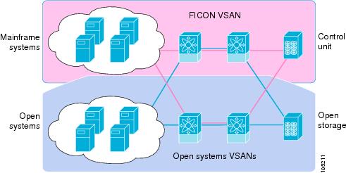
The Cisco MDS 9000 Family supports the Fibre Channel Protocol (FCP), FICON, iSCSI, and FCIP capabilities within a single, high availability platform. This solution simplifies purchasing, reduces deployment and management costs, and reduces the complex evolution to shared mainframe and open systems storage networks (see Figure 24-1).
Figure 24-1 Shared System Storage Network
FCP and FICON are different FC4 protocols and their traffic are independent of each other. If required, devices using these protocols can be isolated using VSANs.
FICON Requirements
The FICON feature has the following requirements:
•
–
–
Note
•
MDS-Specific FICON Advantages
This section explains the additional FICON advantages in Cisco MDS switches.
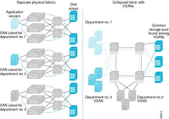
Fabric Optimization with VSANs
Generally, separate physical fabrics have a high level of switch management and have a higher implementation cost. Further, the ports in each island may be over-provisioned depending on the fabric configuration.
By using the Cisco MDS-specific VSAN technology, you can introduce greater efficiency between these physical fabrics by lowering the cost of over-provisioning and reducing the number of switches to be managed.
VSANs also help you to move unused ports nondisruptively and provide a common redundant physical infrastructure (see Figure 24-2).
Figure 24-2 VSAN-Specific Fabric Optimization
VSANs enable global SAN consolidation by allowing you to convert existing SAN islands into virtual SAN islands on a single physical network. It provides hardware-enforced security and separation between applications or departments to allow coexistence on a single network. It also allows virtual rewiring to consolidate your storage infrastructure. You can move assets between departments or applications without the expense and disruption of physical relocation of equipment.
Note
FCIP Support
The multilayer architecture of the Cisco MDS 9000 Family enables a consistent feature set over a protocol-agnostic switch fabric. Cisco MDS 9500 Series and 9200 Series switches transparently integrate Fibre Channel, FICON, and Fibre Channel over IP (FCIP) in one system. The FICON over FCIP feature enables cost-effective access to remotely located mainframe resources. With the Cisco MDS 9000 Family platform, storage replication services such as IBM PPRC and XRC can be extended over metro to global distances using ubiquitous IP infrastructure and simplifying business continuance strategies.
Caution
See Chapter 37, "Configuring IP Storage" for more information on FCIP.
PortChannel Support
The Cisco MDS implementation of FICON provides support for efficient utilization and increased availability of inter-switch links necessary to build stable large-scale SAN environments. PortChannels ensure an enhanced ISL availability and performance in Cisco MDS switches.
See Chapter 13, "Configuring PortChannels" for more information on PortChannels.
VSANs for FICON and FCP Intermixing
Cisco MDS 9000 Family FICON-enabled switches simplify deployment of even the most complex intermix environments. Multiple logical FICON, Z-Series Linux/FCP, and Open-Systems FCP fabrics can be overlaid onto a single physical fabric by simply creating VSANs as required for each service. VSANs provide both hardware isolation and protocol specific fabric services, eliminating the complexity and potential instability of zone-based intermix schemes.
By default, the FICON feature is disabled in all switches in the Cisco MDS 9000 Family. When the FICON feature is disabled, FC IDs can be allocated seamlessly. Intermixed environments are addressed by the Cisco SAN-OS software. The challenge of mixing Fibre Channel Protocol (FCP) and FICON protocols are addressed by Cisco MDS switches when implementing VSANs.
Switches and directors in the Cisco MDS 9000 Family support FCP and FICON protocol intermixing at the port level. If these protocols are intermixed in the same switch, you can use VSANs to isolate FCP and FICON ports.
Tip
Cisco MDS-Supported FICON Features
The Cisco MDS 9000 Family FICON features include:
•
Refer to the Cisco MDS 9500 Series Hardware Installation Guide and the Cisco MDS 9200 Series Hardware Installation Guide).
•
•
•
•
•
•
•
•
•
•
•
–
–
–
See the "Displaying FICON Information" section in this chapter.
•
•
•
•
•
•
•
•
•
•
•
FICON Port Numbering
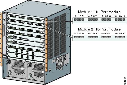
With reference to the FICON feature, ports in Cisco MDS switches are identified by a statically defined 8-bit value known as the port number. Port numbers are assigned based on the module and the slot in the chassis. Port numbers cannot be changed and the first port in a switch always starts with a 0 (see Figure 24-3).
Figure 24-3 Port Number in the Cisco MDS 9000 Family
The FICON port number is assigned based on the front panel location of the port and is specific to the slot in which the module resides. Even if the module is a 16-port module, 32 port numbers are assigned to that module—regardless of the the module's physical presence in the chassis or the port status (up or down).
Note
Table 24-1 lists the port number assignment for the Cisco MDS 9000 Family of switches and directors.
Port Addresses
By default, port numbers are the same as port addresses (see the "Port Swapping" section).
You can swap the port addresses by issuing the ficon swap portnumber command.
Implemented and Unimplemented Port Addresses
An implemented port refers to any port address that is available in the chassis (see Table 24-1).
An unimplemented port refers to any port address that is not available in the chassis (see Table 24-1).
Tip
Installed and Uninstalled Ports
An installed port refers to a port for which all required hardware is present. A specified port number in a VSAN can be implemented, and yet not installed, if any of the following conditions apply:
•
•
•
Another scenario is if VSANs 1 through 5 are FICON-enabled, and trunking-enabled interface fc1/1 has VSANs 3 through 10, then port address 0 is uninstalled in VSAN 1 and 2.
•
FICON Port Numbering Guidelines
The following guidelines apply to FICON port numbers:
•
•
•
•
•
See the "FCIP and PortChannel Port Numbers" section.
FCIP and PortChannel Port Numbers
FCIP and PortChannels cannot be used in a FICON-enabled VSAN unless they are explicitly bound to a port number.
See the "Binding Port Numbers to PortChannels" section and the "Binding Port Numbers to FCIP Interfaces" section.
To find the first available port number to bind a FCIP or PortChannel interface use the show ficon first-available port-number command (see Example 24-3).
Tip
FC ID Allocation
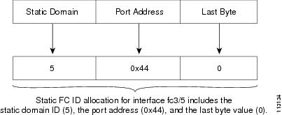
FICON requires a predictable and static FC ID allocation scheme. When FICON is enabled, the FC ID allocated to a device is based on the port address of the port to which it is attached. The port address forms the middle byte of the fabric address. Additionally, the last byte of the fabric address should be the same for all devices in the fabric. By default, the last byte value is 0 and can be configured (see the "FC ID Last Byte" section).
Note
Cisco MDS switches have a dynamic FC ID allocation scheme. When FICON is enabled or disabled on a VSAN, all the ports are flapped to switch from the dynamic to static FC IDs and vice versa (see Figure 24-4).
Figure 24-4 Static FC ID Allocation for FICON
FICON Cascading
The Cisco MDS SAN-OS software allows multiple switches in a FICON network. To configure multiple switches, you must enable and configure fabric binding in that switch (see the "Fabric Binding Configuration" section).
FICON VSAN Prerequisites
To ensure that a FICON VSAN is operationally up, be sure to verify the following requirements:
•
•
•
•
•
•
If any of these requirements are not met, the FICON feature cannot be enabled.
Enabling FICON
By default FICON is disabled in all switches in the Cisco MDS 9000 Family.
You can enable FICON on a per VSAN basis in one of three ways:
•
See the "Setting Up a Basic FICON Configuration" section section in this chapter.
•
See the "Manually Enabling FICON" section.
•
Effects of Enabling FICON
When you enable the FICON feature in Cisco MDS switches, the following apply:
•
•
•
•
See the "FICON Configuration Files" section.
Setting Up a Basic FICON Configuration
This section steps you through the procedure to set up FICON on a specified VSAN in a Cisco MDS 9000 Family switch.
Note
Tip
To enable and set up FICON, follow these steps.
Step 1
switch# setup ficon--- Ficon Configuration Dialog ---This setup utility will guide you through basic Ficon Configurationon the system.Press Enter if you want to skip any dialog. Use ctrl-c at anytimeto skip all remaining dialogs.Step 2
Would you like to enter the basic configuration dialog (yes/no) [yes]: yesThe FICON setup utility guides you through the basic configuration process. Press Ctrl-C at any prompt to end the configuration process.
Step 3
Enter vsan [1-4093]:2Step 4
vsan 2 does not exist, create it? (yes/no) [yes]: yesStep 5
Enable ficon on this vsan? (yes/no) [yes]: yes
Note
Step 6
Configure domain-id for this ficon vsan (1-239):2Step 7
Would you like to configure ficon in cascaded mode: (yes/no) [no]: yesa.
Configure peer wwn (hh:hh:hh:hh:hh:hh:hh:hh): 11:00:02:01:aa:bb:cc:00b.
Configure peer domain (1-239) :4c.
Would you like to configure additional peers: (yes/no) [no]: noStep 8
Enable SNMP to modify port connectivity parameters? (yes/no) [yes]: yesStep 9
Disable Host from modifying port connectivity parameters? (yes/no) [no]: noStep 10
Enable active=saved? (yes/no) [yes]: yesStep 11
Would you like to configure additional ficon vsans (yes/no) [yes]: yesStep 12
Step 13
Note
The following configuration will be applied:fcdomain domain 2 static vsan 1fcdomain restart disruptive vsan 1fabric-binding database vsan 1swwn 11:00:02:01:aa:bb:cc:00 domain 4fabric-binding activate vsan 1zone default-zone permit vsan 1ficon vsan 1no host port controlfcdomain domain 3 static vsan 2fcdomain restart disruptive vsan 2fabric-binding activate vsan 2 forcezone default-zone permit vsan 2ficon vsan 2no host port controlno active equals savedvsan databasevsan 3fcdomain domain 5 static vsan 3fcdomain restart disruptive vsan 3fabric-binding activate vsan 3 forcezone default-zone permit vsan 3ficon vsan 3no snmp port controlno active equals savedWould you like to edit the configuration? (yes/no) [no]: noStep 14
Use this configuration and apply it? (yes/no) [yes]: yes`fcdomain domain 2 static vsan 1``fcdomain restart disruptive vsan 1``fabric-binding database vsan 1``swwn 11:00:02:01:aa:bb:cc:00 domain 4``fabric-binding activate vsan 1``zone default-zone permit vsan 1``ficon vsan 1``no host port control``fcdomain domain 3 static vsan 2``fcdomain restart disruptive vsan 2``fabric-binding activate vsan 2 force``zone default-zone permit vsan 2``ficon vsan 2``no host port control``no active equals saved`
Note
`vsan database``vsan 3``in-order-guarantee vsan 3``fcdomain domain 2 static vsan 3``fcdomain restart disruptive vsan 3``fabric-binding activate vsan 3 force``zone default-zone permit vsan 3``ficon vsan 3``no snmp port control`Performing fast copy config...done.switch#
Manually Enabling FICON
Tip
To manually enable FICON on a VSAN, follow these steps:
Step 1
switch# config t
switch(config)#
Enters configuration mode.
Step 2
switch(config)# vsan database
switch(config-vsan-db)# vsan 5
switch(config-vsan-db)# do show vsan usage
4 vsan configured
configured vsans:1-2,5,26
vsans available for configuration:3-4,6-25,27-4093
switch(config-vsan-db)# exit
Enables VSAN 5.
Step 3
switch(config)# in-order-guarantee vsan 5
Activates in-order delivery for VSAN 5.
See Chapter 21, "Configuring Fibre Channel Routing Services and Protocols."
Step 4
switch(config)# fcdomain domain 2 static vsan 2
Configures the domain ID for VSAN 2.
Step 5
switch(config)# fabric-binding activate vsan 2 force
Activates fabric binding on VSAN 2.
See the "Fabric Binding Configuration" section in this chapter.
Step 6
switch(config)# zone default-zone permit vsan 2
Sets the default zone to permit for VSAN 2.
See the "CUP In-Band Management" section in this chapter.
Step 7
switch(config)# ficon vsan 2
switch(config-ficon)#
Enables FICON on VSAN 2.
switch(config)# no ficon vsan 6
Disables the FICON feature on VSAN 6.
Step 8
switch(config-ficon)# no host port control
Prohibits mainframe users from moving the switch to an offline state.
See the "Host Moves the Switch Offline" section in this chapter.
The code-page Option
FICON strings are coded in Extended Binary-Coded Decimal Interchange Code (EBCDIC) format. Refer to your mainframe documentation for details on the code page options.
Cisco MDS switches support international-5, france, brazil, germany, italy, japan, spain-latinamerica, uk, and us-canada (default) EBCDIC format options.
Tip
To configure the code-page option in a VSAN, follow these steps:
FC ID Last Byte
Caution
FICON requires the last byte of the fabric address to be the same for all allocated FC IDs. By default, this value is set to 0. You can only change the FC ID last byte when the FICON switch is in the offline state.
See the "Moving a FICON VSAN to an Offline State" section.
To assign the last byte for the FC ID, follow these steps:
FICON Host Control
The commands included in this section allow the host (mainframe) to control the Cisco MDS switch.
Host Moves the Switch Offline
By default, hosts are allowed to move the switch to an offline state.
To allow the host to move the switch to an offline state, follow these steps:
Host Changes FICON Port Parameters
By default, mainframe users are not allowed to configure FICON parameters on Cisco MDS switches—they can only query the switch.
Use the host port control command to permit mainframe users to configure FICON parameters.
To configure mainframe access, follow these steps:
Host Controls the Time Stamp
By default, the clock in each VSAN is the same as the switch hardware clock. Each VSAN in a Cisco MDS 9000 Family switch represents a virtual director. The clock and time present in each virtual director can be different.To maintain separate clocks for each VSAN, the Cisco SAN-OS software maintains the difference of the VSAN-specific clock and the hardware-based director clock. When a host (mainframe) sets the time, the Cisco SAN-OS software updates this difference between the clocks. When a host reads the clock, it computes the difference between the VSAN-clock and the current director hardware clock and presents a value to the mainframe.
The VSAN-clock's current time is reported in the output of show ficon vsan vsan-id, show ficon, and show accounting log commands.
To configure host control, follow these steps:
Time Stamp Cleanup
Note
Use the clear ficon vsan vsan-id timestamp command in EXEC mode to clear the VSAN clock.
switch# clear ficon vsan 20 timestampFICON SNMP Control
By default, SNMP users can configure FICON parameters through the Cisco MDS 9000 Family Fabric Manager.
Note
To configure SNMP control, follow these steps:
Running Configuration Automatic Save
Table 24-2 displays the results of active equals saved command and the implicit copy running start command in various scenarios.
If active equals saved is enabled in any FICON-enabled VSAN in the fabric, then the following apply (see Number 1 and 2 in Table 24-2):
•
•
If active equals saved is not enabled in any FICON-enabled VSAN in the fabric, then FICON-specific configuration changes are not saved in the IPL file and an implicit copy running startup is not issued—you must issue the copy running start command explicitly (see Number 3 in Table 24-2).
1 When the Cisco SAN-OS software implicitly issues a copy running start command in the Cisco MDS switch, only a binary configuration is generated—an ASCII configuration is not generated (see Example 24-16). If you wish to generate an additional ASCII configuration at this stage, you must explicitly issue the copy running start command again.
Note
To automatically save the running configuration, follow these steps:
Binding Port Numbers to PortChannels
Caution
You can bind (or associate) a PortChannel with a FICON port number to bring up that interface.
To bind a PortChannel with a FICON port number, follow these steps:
Binding Port Numbers to FCIP Interfaces
You can bind (or associate) a FCIP interface with a FICON port number to bring up that interface.
To bind a FCIP interface with a FICON port number, follow these steps:
Configuring FICON Ports
You can perform FICON configurations on a per-port address basis in the Cisco MDS 9000 Family of switches.
Even if a port is uninstalled, the port address-based configuration is accepted by the Cisco MDS switch. This configuration is applied to the port when the port becomes installed.
Port Blocking
If you block a port, the port is retained in the operationally down state. If you unblock a port, a port initialization is attempted. When a port is blocked, data and control traffic are not allowed on that port.
Physical Fibre Channel port blocks will continue to transmit an Off-Line State (OLS) primitive sequence on a blocked port.
Caution
If a port is shut down, unblocking that port does not initialize the port.
Note
To block or unblock port addresses in a VSAN, follow these steps:
Port Prohibiting
To prevent implemented ports from talking to each other, you can configure prohibits between two or more ports. If you prohibit ports, the specified ports are prevented from communicating with each other.
Note
Tip
Prohibit configurations are always symmetrically applied—if you prohibit Port 0 from talking to port 15, port 15 is automatically prohibited from talking to port 0.
Note
To prohibit port addresses in a VSAN, follow these steps:
Port Address Name Assignment
To assign a port address name, follow these steps:
FICON Configuration Files
You can save up to 16 FICON configuration files on each FICON-enabled VSAN (in persistent storage). The file format is proprietary to IBM. These files can be read and written by IBM hosts using the in-band CUP protocol. Additionally, you can use the Cisco MDS CLI or Fabric Manager applications to operate these FICON configuration files.
Note
When you enable the FICON feature in a VSAN, the switches always use the startup FICON configuration file, called IPL. This file is created with a default configuration as soon as FICON is enabled in a VSAN.
Caution
FICON configuration files contain the following configuration for each implemented port address:
•
•
•
Note
See the "Working with Configuration Files" section on page 7-1 for details on the normal configuration files used by Cisco MDS switches.
Accessing FICON Configuration Files
Only one user can access the configuration file at any given time:
•
•
•
FICON configuration files can be accessed by any host, SNMP, or CLI user who is permitted to access the switch. The locking mechanism in the Cisco SAN-OS software restricts access to one user at a time per file. This lock applies to newly created files and previously saved files. Before accessing any file, you must lock the file and obtain the file key. A new file key is used by the locking mechanism for each lock request. The key is discarded when the lock timeout of 15 seconds expires. The lock timeout value cannot be changed.
Applying the FICON Configuration Files
You can apply the configuration from the saved files to the running configuration using the ficon vsan number apply file filename command.
switch# ficon vsan 2 apply file SampleFileEditing FICON Configuration Files
The configuration file submode allows you to create and edit FICON configuration files. If a specified file does not exist, it is created. Up to 16 files can be saved. Each file name is restricted to eight alphanumeric characters.
To edit the contents of a specified FICON configuration file, follow these steps:
Copying FICON Configuration Files
Use the ficon vsan vsan-id copy file exiting-file-name save-as-file-name command in EXEC mode to copy an existing FICON configuration file.
switch# ficon vsan 20 copy file IPL IPL3You can see the list of existing configuration files by issuing the show ficon vsan vsan-id command.
switch# show ficon vsan 20Ficon information for VSAN 20Ficon is onlineVSAN is activeHost port control is EnabledHost offline control is EnabledUser alert mode is DisabledSNMP port control is EnabledHost set director timestamp is EnabledActive=Saved is EnabledNumber of implemented ports are 250Key Counter is 5FCID last byte is 0Date/Time is same as system time (Wed Dec 3 20:10:45.924591 2003)Device Allegiance not lockedCodepage is us-canadaSaved configuration filesIPLIPL3Port Swapping
The FICON port swap feature is only provided for maintenance purposes.
The FICON port swapping feature causes all configuration associated with old-port-number and new port-number to be swapped, including VSAN configurations.
Cisco MDS switches allow port swapping for non-existent ports as follows:
•
•
•
Tip
Once you swap ports, the switch automatically performs the following actions:
•
•
•
The ficon swap portnumber command is only associated with the two ports concerned. You must issue this VSAN-independent command from EXEC mode.
If you attempt to bring the port up by specifying the ficon swap portnumber old-port-number new-port-number after swap noshut command, you must explicitly issue the no shutdown command to resume traffic.
To swap physical Fibre Channel ports, follow these steps:
Step 1
The specified ports are operationally shut down.
Step 2
Step 3
Note
Port Swapping Guidelines
Be sure to follow these guidelines when using the FICON port swap feature:
•
•
•
•
•
•
Note
Moving a FICON VSAN to an Offline State
Issue the ficon vsan vsan-id offline command in EXEC mode to log out all ports in the VSAN that needs to be suspended.
Issue the EXEC-level ficon vsan vsan-id online command in EXEC mode to remove the offline condition and to allow ports to log on again.
Note
Clearing FICON Device Allegiance
FICON requires serialization of access among multiple mainframes, CLI, and SNMP sessions be maintained on Cisco MDS 9000 Family switches by controlling device allegiance for the currently executing session. Any other session is denied permission to perform configuration changes unless the required allegiance is available.
Caution
You can clear the current device allegiance by issuing the clear ficon vsan vsan-id allegiance command in EXEC mode.
switch# clear ficon vsan 1 allegianceCUP In-Band Management
The Control Unit Port (CUP) protocol configures access control and provides unified storage management capabilities from a mainframe computer. Cisco MDS 9000 FICON-enabled switches are fully IBM CUP standard compliant for in-band management using the IBM S/A OS/390 I/O operations console.
Note
CUP is supported by switches and directors in the Cisco MDS 9000 Family. The CUP function allows the mainframe to manage the Cisco MDS switches.
Host communication includes control functions such as blocking and unblocking ports, as well as monitoring and error reporting functions.
Placing CUPs in a Zone
To place the CUP in a zone, follow these steps.
Step 1
switch# config tswitch(config)# zone default-zone permit vsan 20Step 2
switch# show fcns database vsan 20VSAN 20:--------------------------------------------------------------------------FCID TYPE PWWN (VENDOR) FC4-TYPE:FEATURE--------------------------------------------------------------------------0x0d0d00 N 50:06:04:88:00:1d:60:83 (EMC) FICON:CU0x0dfe00 N 25:00:00:0c:ce:5c:5e:c2 (Cisco) FICON:CUP0x200400 N 50:05:07:63:00:c2:82:d3 (IBM) scsi-fcp FICON:CU f..0x200800 N 50:05:07:64:01:40:15:0f (IBM) FICON:CH0x20fe00 N 20:00:00:0c:30:ac:9e:82 (Cisco) FICON:CUPTotal number of entries = 5
Note
Step 3
switch(config)# zone name Zone1 vsan 20switch(config-zone)# member pwwn 25:00:00:0c:ce:5c:5e:c2
Displaying FICON Information
Use show commands to display all FICON information configured on a switch (see Examples 24-1 to 24-15).
Receiving FICON Alerts
In Example 24-1 the user alert mode is enabled output confirms that you will receive an alert to indicate any changes in the FICON configuration.
Example 24-1 Displays Configured FICON Information
switch# show ficonFicon information for VSAN 20Ficon is onlineVSAN is activeHost port control is EnabledHost offline control is EnabledUser alert mode is EnabledSNMP port control is EnabledHost set director timestamp is EnabledActive=Saved is DisabledNumber of implemented ports are 250Key Counter is 73723FCID last byte is 0Date/Time is set by host to Sun Jun 26 00:04:06.991999 1904Device allegiance is locked by HostCodepage is us-canadaSaved configuration filesIPL_TSIRN00Displaying FICON Port Address Information
Examples 24-2 to 24-5 display FICON Port Address information.
Example 24-2 Displays Port Address Information
switch# show ficon vsan 2 portaddressPort Address 1 is not installed in vsan 2Port number is 1, Interface is fc1/1Port name isPort is not admin blockedProhibited port addresses are 0,241-253,255Port Address 2 is not installed in vsan 2Port number is 2, Interface is fc1/2Port name isPort is not admin blockedProhibited port addresses are 0,241-253,255...Port Address 249 is not installed in vsan 2Port name isPort is not admin blockedProhibited port addresses are 0,241-253,255Port Address 250 is not installed in vsan 2Port name isPort is not admin blockedProhibited port addresses are 0,241-253,255Example 24-3 Displays the Available Port Numbers
switch# show ficon first-available port-numberPort number 129(0x81) is availableIn Example 24-4, the interface column is populated with the corresponding interface if the port number is installed. If the port number is uninstalled, this space remains blank and indicates an unbound port number. For example, 56 is an unbound port number in Example 24-4.
Example 24-4 Displays Port Address Information in a Brief Format
switch# show ficon vsan 2 portaddress 50-55 brief-------------------------------------------------------------------------------Port Port Interface Admin Status Oper FCIDAddress Number Blocked Mode-------------------------------------------------------------------------------50 50 fc2/18 on fcotAbsent -- --51 51 fc2/19 off fcotAbsent -- --52 52 fc2/20 off fcotAbsent -- --53 53 fc2/21 off fcotAbsent -- --54 54 fc2/22 off notConnected -- --55 55 fc2/23 off up FL 0xea000056 56 off up FL 0xea0000Example 24-5 displays the counters in FICON version format 1 (32-bit format)
Example 24-5 Displays Port Address Counter Information
switch# show ficon vsan 20 portaddress 8 countersPort Address 8(0x8) is up in vsan 20Port number is 8(0x8), Interface is fc1/8Version presented 1, Counter size 32b242811 frames input, 9912794 words484 class-2 frames, 242302 class-3 frames0 link control frames, 0 multicast frames0 disparity errors inside frames0 disparity errors outside frames0 frames too big, 0 frames too small0 crc errors, 0 eof errors0 invalid ordered sets0 frames discarded c30 address id errors116620 frames output, 10609188 words0 frame pacing time0 link failures0 loss of sync0 loss of signal0 primitive seq prot errors0 invalid transmission words1 lrr input, 0 ols input, 5 ols output0 error summaryDisplaying IPL File Information
Examples 24-6 to 24-5 display FICON Port Address information.
Example 24-6 Displays the Contents of the Specified FICON Configuration File
switch# show ficon vsan 3 file IPLFICON configuration file IPL in vsan 3Port address 1Port name isPort is not blockedProhibited port addresses are 0,81-253,255Port address 2Port name isPort is not blockedProhibited port addresses are 0,81-253,255Port address 3Port name isPort is not blockedProhibited port addresses are 0,81-253,255Port address 4Port name isPort is not blockedProhibited port addresses are 0,81-253,255...Port address 80Port name isPort is not blockedProhibited port addresses are 0,81-253,255Port address 254Port name isPort is not blockedProhibited port addresses are 0,81-253,255Example 24-7 Displays All FICON Configuration Files
switch# show ficon vsan 2Ficon information for VSAN 2Ficon is enabledVSAN is activeHost control is EnabledHost offline control is EnabledClock alert mode is DisabledUser alert mode is DisabledSNMP control is DisabledActive=Saved is DisabledNumber of implemented ports are 250Key Counter is 9FCID last byte is 0Date/Time is same as system time(Sun Dec 14 01:26:30.273402 1980)Device Allegiance not lockedCodepage is us-canadaSaved configuration filesIPLIPLFILE1Example 24-8 Displays the Specified Port Addresses for a FICON Configuration File
switch# show ficon vsan 2 file iplfile1 portaddress 1-7FICON configuration file IPLFILE1 in vsan 2Port address 1Port name isPort is not blockedProhibited port addresses are 0,241-253,255Port address 2Port name isPort is not blockedProhibited port addresses are 0,241-253,255Port address 3Port name is P3Port is not blockedProhibited port addresses are 0,241-253,255...Port address 7Port name isPort is not blockedProhibited port addresses are 0,241-253,255Displaying the Configured FICON State
If FICON is enabled on a VSAN, you can view the port address information for that VSAN (see Example 24-9).
Example 24-9 Displays the Specified Port Address When FICON Is Enabled
switch# show ficon vsan 2 portaddress 55Port Address 55 is not installed in vsan 2Port number is 55, Interface is fc2/23Port name isPort is not admin blockedProhibited port addresses are 0,241-253,255Admin port mode is FLPort mode is FL, FCID is 0xea0000Displaying a Ports Administrative State
Examples 24-10 to 24-11 display the administrative state of a FICON port. If the port is blocked, the show ficon vsan number portaddress number command displays the blocked state of the port. If a specific port is prohibited, this command also displays the specifically prohibited port (3) along with the ports that are prohibited by default (0, 241 to 253, and 255). If a name is assigned, that name is also displayed.
Example 24-10 Displays an Administratively Unblocked Port
switch# show ficon vsan 2 portaddress 2Port Address 2(0x2) is not installed in vsan 2Port number is 2(0x2), Interface is fc1/2Port name isPort is not admin blockedProhibited port addresses are 0,241-253,255(0,0xf1-0xfd,0xff)Admin port mode is autoPeer is UnknownExample 24-11 Displays an Administratively Blocked Port
switch# show ficon vsan 2 portaddress 1Port Address 2(0x2) is not installed in vsan 2Port number is 2(0x2), Interface is fc1/2Port name is SampleNamePort is admin blockedProhibited port addresses are 0,241-253,255(0,0xf1-0xfd,0xff)Admin port mode is autoPeer is UnknownDisplaying Control Unit Information
Example 24-12 displays configured control device information.
Example 24-12 Displays Control Unit Information
switch# show ficon control-device sb3Control Unit Image:0x80b9c2cVSAN:20 CU:0x20fe00 CUI:0 CUD:0 CURLP:(nil)ASYNC LP:(nil) MODE:1 STATE:1 CQ LEN:0 MAX:0PRIMARY LP: VSAN:0 CH:0x0 CHI:0 CU:0x0 CUI:0ALTERNATE LP: VSAN:0 CH:0x0 CHI:0 CU:0x0 CUI:0Logical Path:0x80b9fb4VSAN:20 CH:0x200600 CHI:15 CU:0x20fe00 CUI:0 STATE:1 FLAGS:0x1LINK: OH:0x0 OC:0x0 IH:0x0 IC:0x0DEV: OH:0x0 OC:0x0 IH:0x0 IC:0x0SENSE: 00 00 00 00 00 00 00 4630 20 00 00 00 00 00 0000 00 00 00 00 00 00 0000 00 00 00 00 00 00 00IUI:0x0 DHF:0x0 CCW:0x0 TOKEN:0x0 PCCW:0x0 FCCW:0x0 PTOKEN:0x0 FTOKEN:0x0CMD:0x0 CCW_FLAGS:0x0 CCW_COUNT:0 CMD_FLAGS:0x0 PRIO:0x0 DATA_COUNT:0STATUS:0x0 FLAGS:0x0 PARAM:0x0 QTP:0x0 DTP:0x0CQ LEN:0 MAX:0 DESTATUS:0x0Displaying Buffer Information
In Example 24-13, the Key Counter column displays the 32-bit value maintained by Cisco MDS switches. This value is incremented when any port changes state in that VSAN. The key counter (a 32-bit value) is incremented when a FICON-related configuration is changed. Host programs can increment this value at the start of the channel program and then perform operations on multiple ports. The director history buffer keeps a log of which port address configuration was changed for each key-counter value.
The director history buffer provides a mechanism to determine the change in the port state from the previous time when a value was contained in the key counter.
Example 24-13 Displays the History Buffer for the Specified VSAN
switch# show ficon vsan 20 director-historyDirector History Buffer for vsan 20---------------------------------------------Key Counter Ports AddressChanged---------------------------------------------74556 4374557 4474558 4574559 4674560 4774561 4874562 4974563 5074564 5174565 5274566 5374567 5474568 5574569 5674570 5774571 5874572 5974573 6074574 6174575 6274576 6374577 64745787457974580 1-3,5,10,12,14-16,34-40,43-45,47-54,56-57,59-6474581 3,574582 647458374584 1-3,10,12,14-16,34-40,43-45,47-54,56-57,59-6474585 174586 274587 3Displaying FICON Information in the Running Configuration
Example 24-14 displays the FICON-related information in the running configuration.
Example 24-14 Displays the Running Configuration Information
switch# show running-configBuilding Configuration ...in-order-guaranteevsan databasevsan 11 name "FICON11" loadbalancing src-dst-idvsan 75 name "FICON75" loadbalancing src-dst-idfcdomain domain 11 static vsan 11fcdomain domain 119 static vsan 75fcdroplatency network 100 vsan 11fcdroplatency network 500 vsan 75fabric-binding enablefabric-binding database vsan 11swwn 20:00:00:0d:ec:01:20:c0 domain 10fabric-binding database vsan 75swwn 20:00:00:0d:ec:00:d6:40 domain 117fabric-binding activate vsan 11fabric-binding activate vsan 75ficon vsan 75interface port-channel 1ficon portnumber 0x80switchport mode Esnmp-server user mblair network-admin auth md5 0x688fa3a2e51ba5538211606e59ac2927 priv 0x688fa3a2e51ba5538211606e59ac2927 localizedkeysnmp-server user wwilson network-admin auth md5 0x688fa3a2e51ba5538211606e59ac2927 priv 0x688fa3a2e51ba5538211606e59ac2927 localizedkeysnmp-server host 171.71.187.101 traps version 2c public udp-port 1163snmp-server host 172.18.2.247 traps version 2c public udp-port 2162vsan databasevsan 75 interface fc1/1...interface mgmt0ip address 172.18.47.39 255.255.255.128switchport speed 100switchport duplex fullno system healthficon vsan 75file IPLDisplaying FICON Information in the Startup Configuration
Example 24-15 displays the FICON-related information in the startup configuration.
Example 24-15 Displays the Startup Configuration
switch# show startup-config...ficon vsan 2file IPLExample 24-16 displays the switch response to an implicitly-issued copy running start command. In this case, only a binary configuration is saved until you explicitly issue the copy running start command again (see Table 24-2)
Example 24-16 Displays the Startup Configuration Status
switch# show startup-configNo ASCII config available since configuration was last saved internallyon account of 'active=saved' mode.Please perform an explicit 'copy running startup` to get ASCII configurationDisplaying FICON-Related Log Information
Example 24-17 and Example 24-18 display the logging information for FICON-related configurations.
Example 24-17 Displays Logging Levels for the FICON Feature
switch# show logging level ficonFacility Default Severity Current Session Severity-------- ---------------- ------------------------ficon 2 20(emergencies) 1(alerts) 2(critical)3(errors) 4(warnings) 5(notifications)6(information) 7(debugging)Example 24-18 Displays FICON -Related Log File Contents
switch# show logging logfile...2004 Feb 25 15:38:50 vegas6 %PORT-5-IF_UP: %$VSAN 75: 2004 Wed Feb 25 13:22:04.131183%$ Interface fc1/8 is up in mode F2004 Feb 25 15:38:50 vegas6 %PORT-5-IF_UP: %$VSAN 75: 2004 Wed Feb 25 13:22:04.131217%$ Interface fc1/9 is up in mode F...2004 Feb 25 15:39:09 vegas6 %PORT-5-IF_TRUNK_UP: %$VSAN 75: 2004 Wed Feb 25 13:22:23.131121%$ Interface fc2/1, vsan 75 is up2004 Feb 25 15:39:09 vegas6 %PORT-5-IF_TRUNK_UP: %$VSAN 75: 2004 Wed Feb 25 13:22:23.131121%$ Interface fc2/2, vsan 75 is up2004 Feb 25 15:39:09 vegas6 %PORT-5-IF_TRUNK_UP: %$VSAN 75: 2004 Wed Feb 25 13:...2004 Feb 25 23:22:36 vegas6 %PORT-5-IF_UP: %$VSAN 75: 2004 Wed Feb 25 21:05:42.99916%$ Interface fc3/6 is up in mode F2004 Feb 25 23:22:37 vegas6 %PORT-5-IF_UP: %$VSAN 75: 2004 Wed Feb 25 21:05:43....Fabric Binding Configuration
The fabric binding feature ensures ISLs are only enabled between specified switches in the fabric binding configuration. Fabric binding is configured on a per-VSAN basis and can only be implemented in FICON VSANs. You can still perform fabric binding configuration in a non-FICON VSAN—these configurations will only come into effect after FICON is enabled.
This feature helps prevent unauthorized switches from joining the fabric or disrupting current fabric operations. It uses the Exchange Fabric Membership Data (EFMD) protocol in FICON networks to ensure that the list of authorized switches is identical in all switches in the fabric.
This section has the following topics:
•
•
•
•
•
•
•
•
•
Port Security Versus Fabric Binding
Port security and fabric binding are two independent features that can be configured to complement each other (see Table 24-3).
Port-level checking for xE-ports
•
•
–
–
While port security complements fabric binding, they are independent features and can be enabled or disabled separately.
Fabric Binding Enforcement
To enforce fabric binding, configure the switch world wide name (sWWN) to specify the xE port connection for each switch. Enforcement of fabric binding policies are done on every activation and when the port tries to come up. However, enforcement of fabric binding at the time of activation happens only if the VSAN is a FICON VSAN. The fabric binding feature requires all sWWNs connected to a switch and their persistent domain IDs to be part of the fabric binding active database.
To configure fabric binding in each switch in the fabric, follow these steps.
Step 1
Step 2
Step 3
Step 4
Step 5
Step 6
Fabric Binding Initiation
The fabric binding feature must be enabled in each switch in the fabric that participates in the fabric binding. By default, this feature is disabled in all switches in the Cisco MDS 9000 Family. The configuration and verification commands for the fabric binding feature are only available when fabric binding is enabled on a switch. When you disable this configuration, all related configurations are automatically discarded.
To enable fabric binding on any participating switch, follow these steps:
View the status of the fabric binding feature of an fabric binding-enabled switch by issuing the show fabric-binding status command.
switch# show fabric-binding statusVSAN 1 :Activated databaseVSAN 4 :No Active databaseSwitch WWN List Configuration
A user-specified fabric binding list contains a list of switch WWNs (sWWNs) within a fabric. If a sWWN attempts to join the fabric, and that sWWN is not in the list or the sWWN is using a domain ID that differs from the one specified in the allowed list, the ISL between the switch and the fabric is automatically isolated in that VSAN and the switch is denied entry into the fabric.
The persistent domain ID must be specified along with the sWWN. Domain ID authorization is required in FICON VSANs where the domains are statically configured and the end devices reject a domain ID change in all switches in the fabric.
To configure a list of sWWNs and domain IDs, follow these steps:
Fabric Binding Activation
The fabric binding maintains a configuration database (config-database) and an active database. The config-database is a read-write database that collects the configurations you perform. These configurations are only enforced upon activation. This activation overwrites the active database with the contents of the config database. The active database is read-only and is the database that checks each switch that attempts to log in.
By default, the fabric binding feature is not activated. You cannot activate the switch if entries existing in the config database conflict with the current state of the fabric. For example, one of the already logged in switches may be denied login by the config database. You can choose to forcefully override these situations.
Note
To activate the fabric binding feature, follow these steps:
Forcing Fabric Binding Activation
If the database activation is rejected due to one or more conflicts listed in the previous section, you may decide to proceed with the activation by using the force option.
To forcefully activate the fabric binding database, follow these steps:
Saving Fabric Binding Configurations
When you save the fabric binding configuration, the config database and the active database are both saved to the startup configuration and are available after a reboot.
Caution
•
switch# fabric-binding database copy vsan 1•
switch# fabric-binding database diff active vsan 1•
switch# fabric-binding database diff config vsan 1
Note
Clearing the Fabric Binding Statistics
Use the clear fabric-binding statistics command to clear all existing statistics from the fabric binding database for a specified VSAN.
switch# clear fabric-binding statistics vsan 1Deleting the Fabric Binding Database
Use the no fabric-binding command in configuration mode to delete the configured database for a specified VSAN.
switch(config)# no fabric-binding database vsan 1Verifying Fabric Binding Configurations
Use the show commands to display all fabric binding information configured on this switch (see Examples 24-19 to 24-27).
Example 24-19 Displays Configured Fabric Binding Database Information
switch# show fabric-binding database--------------------------------------------------Vsan Logging-in Switch WWN Domain-id--------------------------------------------------1 21:00:05:30:23:11:11:11 0x66(102)1 21:00:05:30:23:1a:11:03 0x19(25)1 20:00:00:05:30:00:2a:1e 0xea(234)4 21:00:05:30:23:11:11:11 0x66(102)4 21:00:05:30:23:1a:11:03 0x19(25)61 21:00:05:30:23:1a:11:03 0x19(25)61 21:00:05:30:23:11:11:11 0x66(102)[Total 7 entries]Example 24-20 Displays Active Fabric Binding Information
switch# show fabric-binding database active--------------------------------------------------Vsan Logging-in Switch WWN Domain-id--------------------------------------------------1 21:00:05:30:23:11:11:11 0x66(102)1 21:00:05:30:23:1a:11:03 0x19(25)1 20:00:00:05:30:00:2a:1e 0xea(234)61 21:00:05:30:23:1a:11:03 0x19(25)61 21:00:05:30:23:11:11:11 0x66(102)61 20:00:00:05:30:00:2a:1e 0xef(239)Example 24-21 Displays Active VSAN-Specific Fabric Binding Information
switch# show fabric-binding database active vsan 61--------------------------------------------------Vsan Logging-in Switch WWN Domain-id--------------------------------------------------61 21:00:05:30:23:1a:11:03 0x19(25)61 21:00:05:30:23:11:11:11 0x66(102)61 20:00:00:05:30:00:2a:1e 0xef(239)[Total 3 entries]Example 24-22 Displays Configured VSAN-Specific Fabric Binding Information
switch# show fabric-binding database vsan 4--------------------------------------------------Vsan Logging-in Switch WWN Domain-id--------------------------------------------------4 21:00:05:30:23:11:11:11 0x66(102)4 21:00:05:30:23:1a:11:03 0x19(25)[Total 2 entries]Example 24-23 Displays Fabric Binding Statistics
switch# show fabric-binding statisticsStatistics For VSAN: 1------------------------Number of sWWN permit: 0Number of sWWN deny : 0Total Logins permitted : 0Total Logins denied : 0Statistics For VSAN: 4------------------------Number of sWWN permit: 0Number of sWWN deny : 0Total Logins permitted : 0Total Logins denied : 0Statistics For VSAN: 61------------------------Number of sWWN permit: 0Number of sWWN deny : 0Total Logins permitted : 0Total Logins denied : 0Statistics For VSAN: 345------------------------Number of sWWN permit: 0Number of sWWN deny : 0Total Logins permitted : 0Total Logins denied : 0Statistics For VSAN: 346------------------------Number of sWWN permit: 0Number of sWWN deny : 0Total Logins permitted : 0Total Logins denied : 0Statistics For VSAN: 347------------------------Number of sWWN permit: 0Number of sWWN deny : 0Total Logins permitted : 0Total Logins denied : 0Statistics For VSAN: 348------------------------Number of sWWN permit: 0Number of sWWN deny : 0Total Logins permitted : 0Total Logins denied : 0Statistics For VSAN: 789------------------------Number of sWWN permit: 0Number of sWWN deny : 0Total Logins permitted : 0Total Logins denied : 0Statistics For VSAN: 790------------------------Number of sWWN permit: 0Number of sWWN deny : 0Total Logins permitted : 0Total Logins denied : 0Example 24-24 Displays Fabric Binding Status for Each VSAN
switch# show fabric-binding statusVSAN 1 :Activated databaseVSAN 4 :No Active databaseVSAN 61 :Activated databaseVSAN 345 :No Active databaseVSAN 346 :No Active databaseVSAN 347 :No Active databaseVSAN 348 :No Active databaseVSAN 789 :No Active databaseVSAN 790 :No Active databaseExample 24-25 Displays Fabric Binding Violations
switch# show fabric-binding violations-------------------------------------------------------------------------------VSAN Switch WWN [domain] Last-Time [Repeat count] Reason-------------------------------------------------------------------------------2 20:00:00:05:30:00:4a:1e [0xeb] Nov 25 05:46:14 2003 [2] Domain mismatch3 20:00:00:05:30:00:4a:1e [*] Nov 25 05:44:58 2003 [2] sWWN not found4 20:00:00:05:30:00:4a:1e [*] Nov 25 05:46:25 2003 [1] Database mismatch
Note
Example 24-26 Displays EFMD Statistics
switch# show fabric-binding efmd statisticsEFMD Protocol Statistics for VSAN 1----------------------------------------Merge Requests -> Transmitted : 0 , Received : 0Merge Accepts -> Transmitted : 0 , Received : 0Merge Rejects -> Transmitted : 0 , Received : 0Merge Busy -> Transmitted : 0 , Received : 0Merge Errors -> Transmitted : 0 , Received : 0EFMD Protocol Statistics for VSAN 4----------------------------------------Merge Requests -> Transmitted : 0 , Received : 0Merge Accepts -> Transmitted : 0 , Received : 0Merge Rejects -> Transmitted : 0 , Received : 0Merge Busy -> Transmitted : 0 , Received : 0Merge Errors -> Transmitted : 0 , Received : 0EFMD Protocol Statistics for VSAN 61----------------------------------------Merge Requests -> Transmitted : 0 , Received : 0Merge Accepts -> Transmitted : 0 , Received : 0Merge Rejects -> Transmitted : 0 , Received : 0Merge Busy -> Transmitted : 0 , Received : 0Merge Errors -> Transmitted : 0 , Received : 0Example 24-27 Displays EFMD Statistics for a Specified VSAN
switch# show fabric-binding efmd statistics vsan 4EFMD Protocol Statistics for VSAN 4----------------------------------------Merge Requests -> Transmitted : 0 , Received : 0Merge Accepts -> Transmitted : 0 , Received : 0Merge Rejects -> Transmitted : 0 , Received : 0Merge Busy -> Transmitted : 0 , Received : 0Merge Errors -> Transmitted : 0 , Received : 0Displaying RLIR Information
The Registered Link Incident Report (RLIR) application provides a method for a switchport to send an Link Incident Record (LIR) to a registered Nx-port. It is a highly-available application.
When a LIR is detected in FICON-enabled switches in the Cisco MDS 9000 Family from a RLIR Extended Link Service (ELS). It sends that record to the members in it's Established Registration List (ERL).
In case of multi-switch topology, a Distribute Registered Link Incident Record (DRLIR) Inter Link Service (ILS) is sent to all reachable remote domains along with the RLIR ELS. On receiving the DRLIR ILS, the switch extracts the RLIR ELS and sends to the members of the ERL.
The Nx-ports interested in receiving the RLIR ELS send Link Incident Record Registration (LIRR) ELS request to the management server on the switch. The RLIRs are processed on a per-VSAN basis.
The RLIR data is written to persistent storage when the copy running-config startup-config command is issued.
The show rlir statistics command displays the complete statistics of LIRR, RLIR, and DRLIR frames. It lists the number of frames received, sent, and rejected. Specify the VSAN ID to obtain VSAN statistics for a specific VSAN. If you do not specify the VSAN ID, then the statistics are shown for all active VSANs (see Examples 24-28 and 24-29).
Example 24-28 Displays RLIR Statistics for All VSANs
switch# show rlir statisticsStatistics for VSAN: 1------------------------Number of LIRR received = 0Number of LIRR ACC sent = 0Number of LIRR RJT sent = 0Number of RLIR sent = 0Number of RLIR ACC received = 0Number of RLIR RJT received = 0Number of DRLIR received = 0Number of DRLIR ACC sent = 0Number of DRLIR RJT sent = 0Number of DRLIR sent = 0Number of DRLIR ACC received = 0Number of DRLIR RJT received = 0Statistics for VSAN: 100-------------------------Number of LIRR received = 26Number of LIRR ACC sent = 26Number of LIRR RJT sent = 0Number of RLIR sent = 815Number of RLIR ACC received = 815Number of RLIR RJT received = 0Number of DRLIR received = 417Number of DRLIR ACC sent = 417Number of DRLIR RJT sent = 0Number of DRLIR sent = 914Number of DRLIR ACC received = 828Number of DRLIR RJT received = 0Example 24-29 Displays RLIR Statistics for a Specified VSAN
switch# show rlir statistics vsan 4Statistics for VSAN: 4-------------------------Number of LIRR received = 0Number of LIRR ACC sent = 0Number of LIRR RJT sent = 0Number of RLIR sent = 0Number of RLIR ACC received = 0Number of RLIR RJT received = 0Number of DRLIR received = 0Number of DRLIR ACC sent = 0Number of DRLIR RJT sent = 0Number of DRLIR sent = 0Number of DRLIR ACC received = 0Number of DRLIR RJT received = 0The show rlir erl command shows the list of Nx-ports that are registered to receive the RLIRs with the switch. If the VSAN ID is not specified, the details are shown for all active VSANs (see Examples 24-30 and 24-31).
Example 24-30 Displays All ERLs
switch# show rlir erlEstablished Registration List for VSAN: 2----------------------------------------------FC-ID LIRR FORMAT REGISTERED FOR----------------------------------------------0x0b0200 0x18 always receiveTotal number of entries = 1Established Registration List for VSAN: 100----------------------------------------------FC-ID LIRR FORMAT REGISTERED FOR----------------------------------------------0x0b0500 0x18 conditional receive0x0b0600 0x18 conditional receiveTotal number of entries = 2In Example 24-30, if the Registered For column states that an FC ID is conditional receive, the source port is registered as a valid recipient of subsequent RLIRs. This source port is selected as an RLIR recipient only if no other ERL recipient is selected.
In Example 24-30, if the Registered For column states that an FC ID is always receive, the source port is registered as a valid recipient of subsequent RLIRs. This source port is always selected as an LIR recipient.
Note
Example 24-31 Displays ERLs for the Specified VSAN
switch# show rlir erl vsan 100Established Registration List for VSAN: 100----------------------------------------------FC-ID LIRR FORMAT REGISTERED FOR----------------------------------------------0x0b0500 0x18 conditional receive0x0b0600 0x18 conditional receiveTotal number of entries = 2
Note
Example 24-32 Displays the LIR History
switch# show rlir historyLink incident history----------------------------------------------------------------------------*Host Time StampSwitch Time Stamp Port Interface Link Incident----------------------------------------------------------------------------*Sun Nov 30 21:47:28 2003Sun Nov 30 13:47:55 2003 2 fc1/2 Implicit Incident*Sun Nov 30 22:00:47 2003Sun Nov 30 14:01:14 2003 2 fc1/2 NOS Received*Sun Nov 30 22:00:55 2003Sun Nov 30 14:01:22 2003 2 fc1/2 Implicit Incident*Mon Dec 1 20:14:26 2003Mon Dec 1 12:14:53 2003 4 fc1/4 Implicit Incident*Mon Dec 1 20:14:26 2003Mon Dec 1 12:14:53 2003 4 fc1/4 Implicit Incident*Thu Dec 4 04:43:32 2003Wed Dec 3 20:43:59 2003 2 fc1/2 NOS Received*Thu Dec 4 04:43:41 2003Wed Dec 3 20:44:08 2003 2 fc1/2 Implicit Incident*Thu Dec 4 04:46:53 2003Wed Dec 3 20:47:20 2003 2 fc1/2 NOS Received*Thu Dec 4 04:47:05 2003Wed Dec 3 20:47:32 2003 2 fc1/2 Implicit Incident*Thu Dec 4 04:48:07 2003Wed Dec 3 20:48:34 2003 2 fc1/2 NOS Received*Thu Dec 4 04:48:39 2003Wed Dec 3 20:49:06 2003 2 fc1/2 Implicit Incident*Thu Dec 4 05:02:20 2003Wed Dec 3 21:02:47 2003 2 fc1/2 NOS Received*Thu Dec 4 05:02:29 2003Wed Dec 3 21:02:56 2003 2 fc1/2 Implicit Incident*Thu Dec 4 05:02:47 2003Wed Dec 3 21:03:14 2003 4 fc1/4 NOS Received...Example 24-33 Displays Recent LIRs for a Specified Interface
switch# show rlir recent interface fc1/1-16Recent link incident records----------------------------------------------------------------------------*Host Time StampSwitch Time Stamp Port Interface Link Incident----------------------------------------------------------------------------*Thu Dec 4 05:02:29 2003Wed Dec 3 21:02:56 2003 2 fc1/2 Implicit Incident*Thu Dec 4 05:02:54 2003Wed Dec 3 21:03:21 2003 4 fc1/4 Implicit IncidentExample 24-34 Displays Recent LIRs for a Specified Port Number
switch# show rlir recent portnumber 1-16Recent link incident records----------------------------------------------------------------------------*Host Time StampSwitch Time Stamp Port Interface Link Incident----------------------------------------------------------------------------*Thu Dec 4 05:02:29 2003Wed Dec 3 21:02:56 2003 2 fc1/2 Implicit Incident*Thu Dec 4 05:02:54 2003Wed Dec 3 21:03:21 2003 4 fc1/4 Implicit IncidentClearing RLIR Information
Use the clear rlir statistics command to clear all existing statistics for a specified VSAN.
switch# clear rlir statistics vsan 1Use the clear rlir history command to clear the RLIR history where all link incident records are logged for all interfaces.
switch# clear rlir historyUse the clear rlir recent interface command to clear the most recent RLIR information for a specified interface.
switch# clear rlir recent interface fc 1/2Use the clear rlir recent portnumber command to clear the most recent RLIT information for a specified port number.
switch# clear rlir recent portnumber 16Default Settings
Table 24-4 lists the default settings for FICON features.
Table 24-5 lists the default settings for fabric binding features.