-
Cisco MDS 9000 Family Configuration Guide, Release 2.x
-
New and Changed Information
-
Index
-
Preface
- Part 1 - Getting Started
- Part 2 - Cisco MDS SAN-OS Installation and Switch Management
- Part 3 - Switch Configuration
-
Part 4 - Fabric Configuration
-
Configuring and Managing VSANs
-
Creating Dynamic VSANs
-
Configuring Inter-VSAN Routing
-
Configuring Zones
-
Distributing Device Alias Services
-
Configuring Fibre Channel Routing Services and Protocols
-
Managing FLOGI, Name Server, FDMI, and RSCN Databases
-
Discovering SCSI Targets
-
Configuring FICON
-
Advanced Features and Concepts
-
- Part 5 - Security
- Part 6 - IP Services
- Part 7 - Intelligent Storage Services
- Part 8 - Network and Switch Monitoring
- Part 9 - Traffic Management
- Part 10 - Troubleshooting
-
 Feedback
Table Of Contents
Configuring Inter-VSAN Routing
Unique Domain ID Configuration Options
IVR Configuration Distribution
Enabling Configuration Distribution
Manually Configuring the IVR Topology
Configuring an IVR Topology Database
Activating a Manually Configured IVR Topology
Configuring IVR Topology Automatic Mode
Migrating from IVR Topology Automatic Mode to Manual Mode
Clearing the Configured IVR Topology Database
Non-Unique VSAN IDs Using AFIDs
Verifying the IVR Virtual Domain Configuration
Configuring Persistent FC IDs for IVR
Clearing the IVR fcdomain Database
Verifying the Persistent FC ID Configuration
Creating and Activating IVZs and IVZSs
Configuring LUNs in IVR Zoning
Verifying the QoS Attribute Configuration
Verifying IVZ and IVZS Configuration
Configuring IVR Service Groups
Verifying IVR Service Group Configuration
Configuring IVR Using Read-Only Zoning
Configuring IVR Logging Levels
Verifying Logging Level Configuration
Configuring Inter-VSAN Routing
This chapter explains the Inter-VSAN Routing (IVR) feature and provides details on sharing resources across VSANs using IVR management interfaces provided in the switch.
This chapter includes the following sections:
•
Unique Domain ID Configuration Options
•
•
About IVR
Virtual SANs (VSANs) improve storage area network (SAN) scalability, availability, and security by allowing multiple Fibre Channel SANs to share a common physical infrastructure of switches and ISLs. These benefits are derived from the separation of Fibre Channel services in each VSAN and isolation of traffic between VSANs. Data traffic isolation between the VSANs also inherently prevents sharing of resources attached to a VSAN, such as robotic tape libraries. Using IVR, you can access resources across VSANs without compromising other VSAN benefits.
Data traffic is transported between specific initiators and targets on different VSANs without merging VSANs into a single logical fabric. Fibre Channel control traffic does not flow between VSANs, and initiators cannot access any resource across VSANs other than the resources designated.
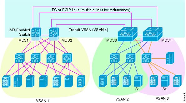
IVR is not limited to VSANs present on a common switch. Routes that traverse one or more VSANs across multiple switches can be established, if necessary, to establish proper interconnections. IVR used in conjunction with FCIP provides more efficient business continuity or disaster recovery solutions (see Figure 18-1).
Note
Figure 18-1 Traffic Continuity Using IVR and FCIP
Note
IVR Features
IVR supports the following features:
•
•
•
•
•
•
IVR Terminology
The following IVR-related terms are used in this chapter:
•
•
•
•
•
•
•
Note
•
Note
•
•
IVR Guidelines
Before configuring an IVR SAN fabric, consider the following guidelines:
•
–
–
•
•
Note
Tip
Note
Domain ID Guidelines
Prior to Cisco MDS SAN-OS Release 2.1(1a), unique domain IDs are required across inter-connected VSANs. Consider the following guidelines for unique domain IDs:
•
•
Note
Note
Transit VSAN Guidelines
Consider the following guidelines for transit VSANs:
•
–
–
•
•
Border Switch Guidelines
Before configuring border switches, consider the following guidelines:
•
•
•
•
•
IVR Configuration
To configure IVR in a SAN fabric, follow these steps:
Step 1
Step 2
Step 3
Step 4
Step 5
Step 6
Step 7
Step 8
Unique Domain ID Configuration Options
If you are not using IVR NAT, you must use unique domain IDs. You can configure unique domain IDs using one of two options:
•
•
Note
Enabling IVR
The IVR feature must be enabled in all border switches in the fabric that participate in the IVR. By default, this feature is disabled in all switches in the Cisco MDS 9000 Family. You can manually enable IVR on all required switches in the fabric or configure fabric-wide distribution of the IVR configuration ("IVR Configuration Distribution" section).
The configuration and verification commands for the IVR feature are only available when IVR is enabled on a switch. When you disable this configuration, all related configurations are automatically discarded.
To enable IVR on any participating switch, follow these steps:
Step 1
switch# config t
Enters configuration mode.
Step 2
switch(config)# ivr enable
Enables IVR on the switch.
switch(config)# no ivr enable
Disables (default) IVR on the switch.
IVR Configuration Distribution
The IVR feature uses the Cisco Fabric Services (CFS) infrastructure to enable efficient configuration management and to provide a single point of configuration for the entire fabric in the VSAN (see Chapter 5, "Using the CFS Infrastructure").
The following configurations are distributed:
•
•
•
•
•
•
Note
Database Implementation
The IVR feature uses three databases to accept and implement configurations.
•
•
•
Enabling Configuration Distribution
To enable IVR configuration distribution, follow these steps:
Locking the Fabric
The first action that modifies the database creates the pending database and locks the feature in the VSAN. Once you lock the fabric, the following situations apply:
•
•
Committing the Changes
If you commit the changes made to the active database, the configuration is committed to all the switches in the fabric. On a successful commit, the configuration change is applied throughout the fabric and the lock is released.
To commit IVR configuration changes, follow these steps:
Step 1
switch# config t
switch(config)#
Enters configuration mode.
Step 2
switch(config)# ivr commit
Commits the IVR changes.
Discarding the Changes
If you discard (abort) the changes made to the pending database, the configuration database remains unaffected and the lock is released.
To discard IVR configuration changes, follow these steps:
Step 1
switch# config t
switch(config)#
Enters configuration mode.
Step 2
switch(config)# ivr abort
Discards the IVR changes and clears the pending configuration database.
Clearing a Locked Session
If you have performed an IVR task and have forgotten to release the lock by either committing or discarding the changes, an administrator can release the lock from any switch in the fabric. If the administrator performs this task, your changes to the pending database are discarded and the fabric lock is released.
Tip
To use administrative privileges and release a locked DPVM session, use the clear ivr session command in EXEC mode.
switch# clear ivr sessionAbout IVR NAT
Prior to Cisco MDS SAN-OS Release 2.1(1a), IVR required unique domain IDs for all switches in the fabric. As of Cisco MDS SAN-OS Release 2.1(1a), you can enable IVR Network Address Translation (NAT) to allow non-unique domain IDs. This feature simplifies the deployment of IVR in an existing fabric where non-unique domain IDs might be present.
IVR NAT must be running on all border switches in the fabric IVR configuration distribution. IVR configuration distribution is supported by the CFS infrastructure (see the "IVR Configuration Distribution" section). By default, IVR NAT, and IVR configuration distribution are disabled in all switches in the Cisco MDS 9000 Family.
Note
Note
Note
IVR NAT virtualizes the switches in other VSANs by using local VSAN for the destination IDs in the Fibre Channel headers. In some Extended Link Service message types, the destinations IDs are part of the payload. In these cases, IVR NAT replaces the actual destination ID with the virtualized destination ID. IVR NAT supports destination ID replacement in the Extended Link Service messages described in Table 18-1.
If you have a message that is not recognized by IVR NAT and contains the destination ID in the payload, you cannot use IVR with NAT in your topology. You can still use IVR with unique domain IDs.
Enabling IVR NAT
The configuration and verification commands for the IVR feature are only available when IVR is enabled on a switch. When you disable this configuration, all related configurations are automatically discarded.
To configure IVR NAT, follow these steps:
Step 1
switch# config t
Enters configuration mode.
Step 2
switch(config)# ivr nat
Enables IVR NAT on the switch.
switch(config)# no ivr nat
Disables (default) IVR NAT on the switch.
About IVR Topologies
IVR must know about the topology of the IVR-enabled switches in the fabric to function properly. You can specify the topology two ways:
•
If you manually configure the IVR topology, you must ensure that the IVR topology exists on every IVR-enabled switch in the fabric. You can configure the IVR topology manually on each IVR-enabled switch or you can use CFS to distribute the configuration automatically (see the "Database Merge Guidelines" section).
If an IVR-enabled switch is removed from the network, the IVR topology database must be updated to reflect the change.
•
As of Cisco MDS SAN-OS Release 2.1(1a), you can configure IVR topology automatic mode. Automatic mode uses CFS configuration distribution to dynamically learn and maintain up-to-date information about the topology of the IVR-enabled switches in the network.
If a manually configured IVR topology database exists, automatic mode initially uses that topology information. This reduces disruption in the network by gradually migrating from a user-specified topology database to an automatically learned topology database. Then the user-configured topology entries that are not part of the network are aged out in about three minutes and new entries that are not part of user configured database are added as they are learned from the network.
Configuring IVR Topologies
This section describes how to manually configure an IVR topology or how to configure IVR topology automatic mode.
Manually Configuring the IVR Topology
You can have up to 64 VSANs (or 128 VSANs as of Cisco MDS SAN-OS Release 2.1(1a)) in an IVR topology. Specify the IVR topology using the following information:
•
•
•
Note
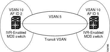
Figure 18-2 Example IVR Topology with Non-Unique VSAN IDs Using AFIDs
Note
Caution
Configuring an IVR Topology Database
Use the show wwn switch command to obtain the switch WWNs of the IVR-enabled switches.
To configure a user-defined IVR topology database, follow these steps:
View your configured IVR topology using the show ivr vsan-topology command. In the following example output, VSAN 2 is the transit VSAN between VSANs 1, 5, and 6.
switch# show ivr vsan-topologyAFID SWITCH WWN Active Cfg. VSANS--------------------------------------------------------------1 20:00:00:05:30:01:1b:c2 * no yes 1-21 20:02:00:44:22:00:4a:05 no yes 1-2,61 20:02:00:44:22:00:4a:07 no yes 2-5Total: 3 entries in active and configured IVR VSAN-TopologyCurrent Status: Inter-VSAN topology is INACTIVE
Note
Tip
Activating a Manually Configured IVR Topology
After manually configuring the IVR topology database, you must activate it.
Caution
To activate a manually configured IVR topology, follow these steps:
Step 1
switch# config t
switch(config)#
Enters configuration mode.
Step 2
switch(config)# ivr vsan-topology activate
Activates the configured IVR topology.
View your active IVR topology using the show ivr vsan-topology command.
switch# show ivr vsan-topologyAFID SWITCH WWN Active Cfg. VSANS--------------------------------------------------------------1 20:00:00:05:30:01:1b:c2 * yes yes 1-21 20:02:00:44:22:00:4a:05 yes yes 1-2,61 20:02:00:44:22:00:4a:07 yes yes 2-5Total: 3 entries in active and configured IVR VSAN-TopologyCurrent Status: Inter-VSAN topology is ACTIVELast activation time: Mon Mar 24 07:19:53 1980Configuring IVR Topology Automatic Mode
As of Cisco MDS SAN-OS Release 2.1(1a), you can configure IVR topology automatic mode.
Note
To configure IVR topology automatic mode, follow these steps:
View automatically discovered IVR topology using the show ivr vsan-topology command.
switch# show ivr vsan-topologyAFID SWITCH WWN Active Cfg. VSANS--------------------------------------------------------------1 20:00:00:05:30:01:1b:c2 * yes yes 1-21 20:02:00:44:22:00:4a:05 yes yes 1-2,61 20:02:00:44:22:00:4a:07 yes yes 2-5Total: 3 entries in active and configured IVR VSAN-TopologyCurrent Status: Inter-VSAN topology is AUTOLast activation time: Mon Mar 24 07:19:53 1980Migrating from IVR Topology Automatic Mode to Manual Mode
If you want to migrate the active IVR VSAN topology database from automatic mode to user-configured mode, first copy the active IVR VSAN topology database to the user-configured IVR VSAN topology database before switching modes. To migrate from automatic mode to manual mode, follow these steps:
Clearing the Configured IVR Topology Database
To clear the user-configured IVR VSAN topology database using, follow these steps:
Step 1
switch# config t
switch(config)#
Enters configuration mode.
Step 2
switch(config)# no ivr vsan-topology database
Clears the previously created IVR topology.
Verifying the IVR Topology
You can verify the IVR topology by using the show ivr vsan-topology command. See Example 18-1 to Example 18-3.
Example 18-1 Displays the Configured IVR VSAN Topology
switch# show ivr vsan-topologyAFID SWITCH WWN Active Cfg. VSANS--------------------------------------------------------------1 20:00:00:05:30:01:1b:c2 * yes yes 1-21 20:02:00:44:22:00:4a:05 yes yes 1-2,61 20:02:00:44:22:00:4a:07 yes yes 2-5Total: 5 entries in active and configured IVR VSAN-TopologyCurrent Status: Inter-VSAN topology is ACTIVELast activation time: Sat Mar 22 21:46:15 1980The asterisk (*) indicates the local switch.
Example 18-2 Displays the Active IVR VSAN Topology
switch# show ivr vsan-topology activeAFID SWITCH WWN Active Cfg. VSANS--------------------------------------------------------------1 20:00:00:05:30:01:1b:c2 * yes yes 1-21 20:02:00:44:22:00:4a:05 yes yes 1-2,61 20:02:00:44:22:00:4a:07 yes yes 2-5Total: 5 entries in active IVR VSAN-TopologyCurrent Status: Inter-VSAN topology is ACTIVELast activation time: Sat Mar 22 21:46:15Example 18-3 Displays the Configured IVR VSAN Topology
switch# show ivr vsan-topology configuredAFID SWITCH WWN Active Cfg. VSANS--------------------------------------------------------------1 20:00:00:05:30:01:1b:c2 * yes yes 1-21 20:02:00:44:22:00:4a:05 yes yes 1-2,61 20:02:00:44:22:00:4a:07 yes yes 2-5Total: 5 entries in configured IVR VSAN-TopologyNon-Unique VSAN IDs Using AFIDs
As of Cisco MDS SAN-OS Release 2.1(1a), you can configure more than one AFID. This feature allows more than one VSAN in the network with the same VSAN ID. Using this feature you can avoid downtime when enabling IVR between fabrics that contain VSANs with the same ID. However, for VSANs with the same ID to communicate, there must be a transit VSAN with a different VSAN ID between the source and target VSANs.
Note
Configuring the AFID Database
To configure the AFID database, follow these steps:
Verifying the AFID Database
View the contents of the AFID database using the show autonomous-fabric-id database command.
switch# show autonomous-fabric-id databaseSWITCH WWN Default-AFID--------------------------------------------------------------20:00:00:0c:91:90:3e:80 5Total: 1 entry in default AFID tableSWITCH WWN AFID VSANS--------------------------------------------------------------20:00:00:0c:91:90:3e:80 10 1,2,5-8Total: 1 entry in AFID tableAdding IVR Virtual Domain
In a remote VSAN, the IVR application does not automatically add the virtual domain to the assigned domain list. Some switches (for example, the Cisco SN5428) do not query the remote name server until the remote domain appears in the assigned domain list in the fabric. In such cases, add the IVR virtual domains in a specific VSAN(s) to the assigned domain list in that VSAN. When adding IVR domains, all IVR virtual domains that are currently present in the fabric (and any virtual domain that is created in the future) will appear in the assigned domain list for that VSAN.
Tip
Tip
To add an IVR virtual domain to a specified VSAN, follow these steps:
When you enable the IVR virtual domains, links may fail to come up due to overlapping virtual domain identifiers. If so, temporarily withdraw the overlapping virtual domain from that VSAN.
Note
Use the ivr withdraw domain command in EXEC mode to temporarily withdraw the overlapping virtual domain interfaces from the affected VSAN.
Verifying the IVR Virtual Domain Configuration
View the status of the IVR virtual domain configuration using the show ivr virtual-fcdomain-add-status command.
switch# show ivr virtual-fcdomain-add-statusIVR virtual domains are added to fcdomain list in VSANS: 1(As well as to VSANs in interoperability mode 2 or 3)Persistent FC IDs for IVR
As of Cisco MDS SAN-OS Release 2.1(2), you can configure persistent FC IDs for IVR. Persistent FC IDs across reboot improves IVR management by providing the following features:
•
•
The benefits of persistent FC IDs for IVR are as follows:
•
•
•
You can configure two types of database entries for IVR FC IDs:
•
–
–
–
–
–
•
–
–
–
–
Note
Note
Configuring Persistent FC IDs for IVR
To configure persistent FC IDs for IVR in Cisco MDS SAN-OS Release 2.1(2) and later, follow these steps:
Clearing the IVR fcdomain Database
You might want to clear the IVR fcdomain database. You can do this using the following command:
switch# clear ivr fcdomain databaseVerifying the Persistent FC ID Configuration
Verify the persistent FC ID configuration using the show ivr fcdomain database command. See Example 18-4 and Example 18-5
Example 18-4 Displays All IVR fcdomain Database Entries
switch# show ivr fcdomain database----------------------------------------------------AFID Vsan Native-AFID Native-Vsan Virtual-domain----------------------------------------------------1 2 10 11 0xc(12)21 22 20 11 0xc(12)Number of Virtual-domain entries: 2----------------------------------------------------AFID Vsan Pwwn Virtual-fcid----------------------------------------------------21 22 11:22:33:44:55:66:77:88 0x11446621 22 21:22:33:44:55:66:77:88 0x0c446621 22 21:22:33:44:55:66:78:88 0x0c4466Number of Virtual-fcid entries: 3Example 18-5 Displays the IVR fcdomain Database Entries for a Specific AFID and VSAN
switch# show ivr fcdomain database autonomous-fabric-num 21 vsan 22----------------------------------------------------AFID Vsan Native-AFID Native-Vsan Virtual-domain----------------------------------------------------21 22 20 11 0xc(12)Number of Virtual-domain entries: 1----------------------------------------------------AFID Vsan Pwwn Virtual-fcid----------------------------------------------------21 22 11:22:33:44:55:66:77:88 0x11446621 22 21:22:33:44:55:66:77:88 0x0c446621 22 21:22:33:44:55:66:78:88 0x0c4466Number of Virtual-fcid entries: 3About IVZs and IVZSs
As part of the IVR configuration, you need to configure one or more IVZs to enable cross-VSAN communication. To achieve this result, you must specify each IVZ as a set of (pWWN, VSAN) entries. Like zones, several IVZs can be configured to belong to an IVR zone. You can define several IVZSs and activate only one of the defined IVZSs.
Note
Caution
IVZs Versus Zones
Table 18-2 identifies the key differences between IVZs and zones.
Automatic IVZ Creation
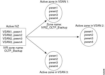
Figure 18-3 depicts an IVZ consisting of four members. To allow pwwn1 to communicate with pwwn2, they must be in the same zone in VSAN 1, as well as in VSAN 2. If they are not in the same zone, then the hard-zoning ACL entries will prohibit pwwn1 from communicating with pwwn2.
A zone corresponding to each active IVZ is automatically created in each edge VSAN specified in the active IVZ. All pWWNs in the IVZ are members of these zones in each VSAN.
Figure 18-3 Creating Zones on IVZ Activation
The zones are created automatically by the IVR process when an IVZS is activated. They are not stored in full zone set database and are lost when the switch reboots or when a new zone set is activated. The IVR feature monitors these events and adds the zones corresponding to the active IVZS configuration when a new zone set is activated. Like zone sets, IVR zone sets are also activated nondisruptively.
Note
IVZ and IVZS names are restricted to 64 alphanumeric characters.
Caution
Configuring IVZs and IVZSs
This section describes how to configure IVZs and IVZSs.
Creating and Activating IVZs and IVZSs
When you activate an IVZS, IVR automatically adds an IVZ to the regular active zone set of each edge VSAN. If a VSAN does not have an active zone set, IVR can only activate an IVZS using the force option, which causes IVR to create an active zone set called "nozoneset" and adds the IVZ to that active zone set.
Caution
Note
To create and activate IVZs and IVZSs, follow these steps:
Configuring LUNs in IVR Zoning
LUN zoning can be used between members of active IVZs. Prior to Cisco MDS SAN-OS Release 2.1(1a), you can configure the service by creating and activating LUN zones between the desired IVZ members in all relevant edge VSANs using the zoning interface. As of Cisco MDS SAN-OS Release 2.1(1a), IVR directly supports LUN zoning. For more details on the advantages of LUN zoning, see the "About LUN Zoning" section on page 19-17.
To configure LUNs in IVR zoning in Cisco MDS SAN-OS Release 2.1(1a) or later, follow these steps:
Note
Configuring the QoS Attribute
As of Cisco MDS SAN-OS Release 2.1(1a), you can configure a QoS attribute for an IVZ. To configure QoS for an IVZ, follow these steps:
Note
Verifying the QoS Attribute Configuration
Verify the QoS attribute configuration for an IVR zone using the show ivr zone command.
switch(config)# show ivr zonezone name IvrZoneattribute qos priority mediumUsing the force Option
Use the force option to activate the specified IVZS. Table 18-3 lists the various scenarios with and without the force option.
Table 18-3 IVR Scenarios with and without the force Option.
1
Deny
No active zone set
No
Failure
No
No
2
Yes
Success
Yes
No
31
Deny
Active zone set present
No/Yes
Success
Yes
No
4
Permit
No active zone set
or
Active zone set presentNo
Failure
No
No
5
Yes
Success
Yes
Yes
1 We recommend that you use the Case 3 scenario.
Caution
Clearing the IVZ Database
Note
To clear the IVZ database, use the clear ivr zone database command.
switch# clear ivr zone databaseThis command clears all configured IVZ information.
Note
Verifying IVZ and IVZS Configuration
Verify the IVZ and IVZS configurations using the show ivr zone and show ivr zoneset commands. See Example 18-6 to Example 18-14.
Example 18-6 Displays the IVZ Configuration
switch# show ivr zonezone name sample_vsan2-3pwwn 21:00:00:e0:8b:02:ca:4a vsan 3pwwn 21:00:00:20:37:c8:5c:6b vsan 2zone name ivr_qa_z_allpwwn 21:00:00:e0:8b:06:d9:1d vsan 1pwwn 21:01:00:e0:8b:2e:80:93 vsan 4pwwn 10:00:00:00:c9:2d:5a:dd vsan 1pwwn 10:00:00:00:c9:2d:5a:de vsan 2pwwn 21:00:00:20:37:5b:ce:af vsan 6pwwn 21:00:00:20:37:39:6b:dd vsan 6pwwn 22:00:00:20:37:39:6b:dd vsan 3pwwn 22:00:00:20:37:5b:ce:af vsan 3pwwn 50:06:04:82:bc:01:c3:84 vsan 5Example 18-7 Displays Information for a Specified IVZ
switch# show ivr zone name sample_vsan2-3zone name sample_vsan2-3pwwn 21:00:00:e0:8b:02:ca:4a vsan 3pwwn 21:00:00:20:37:c8:5c:6b vsan 2Example 18-8 Displays the Specified Zone in the Active IVZ
switch# show ivr zone name sample_vsan2-3 activezone name sample_vsan2-3pwwn 21:00:00:e0:8b:02:ca:4a vsan 3pwwn 21:00:00:20:37:c8:5c:6b vsan 2Example 18-9 Displays the IVZS Configuration
switch# show ivr zonesetzoneset name ivr_qa_zs_allzone name ivr_qa_z_allpwwn 21:00:00:e0:8b:06:d9:1d vsan 1pwwn 21:01:00:e0:8b:2e:80:93 vsan 4pwwn 10:00:00:00:c9:2d:5a:dd vsan 1pwwn 10:00:00:00:c9:2d:5a:de vsan 2pwwn 21:00:00:20:37:5b:ce:af vsan 6pwwn 21:00:00:20:37:39:6b:dd vsan 6pwwn 22:00:00:20:37:39:6b:dd vsan 3pwwn 22:00:00:20:37:5b:ce:af vsan 3pwwn 50:06:04:82:bc:01:c3:84 vsan 5zoneset name IVR_ZoneSet1zone name sample_vsan2-3pwwn 21:00:00:e0:8b:02:ca:4a vsan 3pwwn 21:00:00:20:37:c8:5c:6b vsan 2Example 18-10 Displays the Active IVZS Configuration
switch# show ivr zoneset activezoneset name IVR_ZoneSet1zone name sample_vsan2-3pwwn 21:00:00:e0:8b:02:ca:4a vsan 3pwwn 21:00:00:20:37:c8:5c:6b vsan 2Example 18-11 Displays the Specified IVZS Configuration
switch# show ivr zoneset name IVR_ZoneSet1zoneset name IVR_ZoneSet1zone name sample_vsan2-3pwwn 21:00:00:e0:8b:02:ca:4a vsan 3pwwn 21:00:00:20:37:c8:5c:6b vsan 2Example 18-12 Displays Brief Information for All IVZSs
switch# show ivr zoneset brief Activezoneset name IVR_ZoneSet1zone name sample_vsan2-3Example 18-13 Displays Brief Information for the Active IVZS
switch# show ivr zoneset brief Activezoneset name IVR_ZoneSet1zone name sample_vsan2-3Example 18-14 Displays Status Information for the IVZS
switch# show ivr zoneset statusZoneset Status_______________name : IVR_ZoneSet1state : activation successlast activate time : Sat Mar 22 21:38:46 1980force option : offstatus per vsan:__________________vsan status____ ______1 active2 active
Tip
Note
About IVR Service Groups
In a complex network topology, you might only have a few IVR-enabled VSANs. To reduce the amount of traffic to non-IVR-enabled VSANs, you can configure a service group that restricts the traffic to the IVR-enabled VSANs. Only one service group is allowed in a network. When a new IVR-enabled switch is added to the network, you must update the service group to include the new VSANs.
Note
Configuring IVR Service Groups
To configure an IVR service group, follow these steps:
Verifying IVR Service Group Configuration
Use the show ivr service-group database command to view the IVR service group database configuration.
switch# show ivr service-group databaseSG-ID SG-NAME AFID VSANS------------------------------------------------------------------------------1 IVR-SG1 10 1-2,6-101 IVR-SG1 11 1Total: 2 entries in service group tableIVR Interoperability
When using the IVR feature, all border switches in a given fabric must be Cisco MDS switches. However, other switches in the fabric may be non-MDS switches. For example, end devices that are members of the active IVZS may be connected to non-MDS switches. Non-MDS switches may also be present in the transit VSAN(s) or in the edge VSANs if one of the interop modes is enabled.
See the "Switch Interoperability" section on page 25-9.
Configuring IVR Using Read-Only Zoning
Read-only zoning (with or without LUNs) can be used between members of active IVR zones. To configure this service, you must create and activate read-only zones between the desired IVZ members in all relevant edge VSANs using the zoning interface.
Note
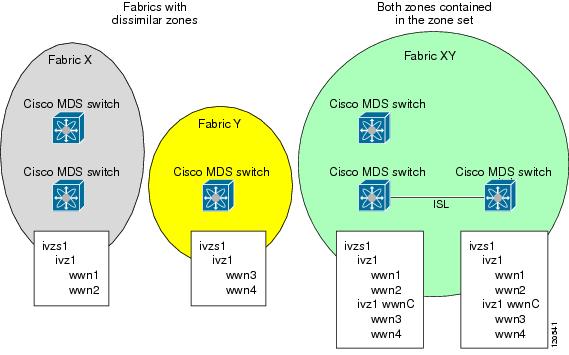
Database Merge Guidelines
A database merge refers to a union of the configuration database and static (unlearned) entries in the active database. Refer to the "CFS Merge Support" section on page 5-7 for detailed concepts.
•
–
–
Figure 18-4 Fabric Merge Consequences
•
•
–
–
–
–
–
Note
–
–
–
–
Table 18-4 describes the results of a CFS merge of two IVR-enabled fabrics under different conditions.
Caution
Configuring IVR Logging Levels
To configure the severity level for logging messages from the IVR feature, follow these steps:
Verifying Logging Level Configuration
Use the show logging level command to view the configured logging level for the IVR feature.
switch# show logging levelFacility Default Severity Current Session Severity-------- ---------------- ------------------------...ivr 5 4...0(emergencies) 1(alerts) 2(critical)3(errors) 4(warnings) 5(notifications)6(information) 7(debugging)Example Configurations
This section provides IVR configurations examples and includes the following topics:
•
Manual Topology Configuration
This section provides the configuration steps to manually configure the example illustrated in Figure 18-1.
Step 1
mds# config tEnter configuration commands, one per line. End with CNTL/Z.mds (config)# ivr enablemds (config)# exitStep 2
mds# show ivrInter-VSAN Routing is enabledInter-VSAN enabled switches---------------------------No IVR-enabled VSAN is active. Check VSAN-Topology configuration.Inter-VSAN topology status--------------------------Current Status: Inter-VSAN topology is INACTIVEInter-VSAN zoneset status-------------------------name :state : idlelast activate time :Step 3
mds# config tEnter configuration commands, one per line. End with CNTL/Z.mds (config)# ivr distributionmds (config)# exitStep 4
mds# conf tEnter configuration commands, one per line. End with CNTL/Z.mds(config)# ivr vsan-topology databasemds(config-ivr-topology-db)# autonomous-fabric-id 1 switch-wwn 20:00:00:05:40:01:1b:c2 vsan-ranges 1,4mds(config-ivr-topology-db)# autonomous-fabric-id 1 switch-wwn 20:02:00:44:22:00:4a:08 vsan-ranges 1,4mds(config-ivr-topology-db)# autonomous-fabric-id 1 switch-wwn 20:00:00:44:22:02:8a:04 vsan-ranges 2-4mds(config-ivr-topology-db)# autonomous-fabric-id 1 switch-wwn 20:00:00:44:22:40:aa:16 vsan-ranges 2-4mds(config-ivr-topology-db)# exitStep 5
Note
mds(config)# do show ivr vsan-topologyAFID SWITCH WWN Active Cfg. VSANS--------------------------------------------------------------1 20:00:00:05:40:01:1b:c2 * no yes 1,41 20:00:00:44:22:00:4a:08 no yes 1,41 20:00:00:44:22:02:8a:04 no yes 2-41 20:00:00:44:22:40:aa:16 no yes 2-4Total: 4 entries in active and configured IVR VSAN-TopologyCurrent Status: Inter-VSAN topology is INACTIVEStep 6
mds(config)# ivr vsan-topology activateStep 7
mds(config)# do show ivr vsan-topologyAFID SWITCH WWN Active Cfg. VSANS--------------------------------------------------------------1 20:00:00:05:40:01:1b:c2 * yes yes 1,41 20:00:00:44:22:00:4a:08 yes yes 1,41 20:00:00:44:22:02:8a:04 yes yes 2-41 20:00:00:44:22:40:aa:16 yes yes 2-4Total: 4 entries in active and configured IVR VSAN-TopologyCurrent Status: Inter-VSAN topology is ACTIVELast activation time: Tue May 20 23:14:59 1980Step 8
•
•
Tip
mds(config)# ivr zoneset name tape_server1_server2mds(config-ivr-zoneset)# zone name tape_server1mds(config-ivr-zoneset-zone)# member pwwn 10:02:50:45:32:20:7a:52 vsan 1mds(config-ivr-zoneset-zone)# member pwwn 10:02:66:45:00:20:89:04 vsan 2mds(config-ivr-zoneset-zone)# exitmds(config-ivr-zoneset)# zone name tape_server2mds(config-ivr-zoneset-zone)# member pwwn 10:02:50:45:32:20:7a:52 vsan 1mds(config-ivr-zoneset-zone)# member pwwn 10:00:ad:51:78:33:f9:86 vsan 3mds(config-ivr-zoneset-zone)# exitStep 9
mds(config)# do show ivr zonesetzoneset name tape_server1_server2zone name tape_server1pwwn 10:02:50:45:32:20:7a:52 vsan 1pwwn 10:02:66:45:00:20:89:04 vsan 2zone name tape_server2pwwn 10:02:50:45:32:20:7a:52 vsan 1pwwn 10:00:ad:51:78:33:f9:86 vsan 3Step 10
mds(config)# do show zoneset active vsan 1zoneset name finance_dept vsan 1zone name accounts_database vsan 1pwwn 10:00:23:11:ed:f6:23:12pwwn 10:00:56:43:11:56:fe:eezone name $default_zone$ vsan 1Step 11
mds(config)# ivr zoneset activate name tape_server1_server2zoneset activation initiated. check inter-VSAN zoneset statusmds(config)# exitStep 12
mds# show ivr zoneset activezoneset name tape_server1_server2zone name tape_server1pwwn 10:02:50:45:32:20:7a:52 vsan 1pwwn 10:02:66:45:00:20:89:04 vsan 2zone name tape_server2pwwn 10:02:50:45:32:20:7a:52 vsan 1pwwn 10:00:ad:51:78:33:f9:86 vsan 3Step 13
mds# show zoneset active vsan 1zoneset name finance_dept vsan 1zone name accounts_database vsan 1pwwn 10:00:23:11:ed:f6:23:12pwwn 10:00:56:43:11:56:fe:eezone name IVRZ_tape_server1 vsan 1pwwn 10:02:66:45:00:20:89:04pwwn 10:02:50:45:32:20:7a:52zone name IVRZ_tape_server2 vsan 1pwwn 10:02:50:45:32:20:7a:52pwwn 10:00:ad:51:78:33:f9:86zone name $default_zone$ vsan 1mds# show ivr zoneset statusZoneset Status______________name : tape_server1_server2state : activation successlast activate time : Tue May 20 23:23:01 1980force option : onstatus per vsan:__________________vsan status____ ______1 active
Auto-Topology Configuration
This section provides example configuration steps for configuring IVR auto-topology supported in Cisco SAN-OS Release 2.1(1a) and later.
Step 1
switch# config tEnter configuration commands, one per line. End with CNTL/Z.switch(config)# ivr enableswitch(config)# exitswitch#Step 2
switch# show ivrInter-VSAN Routing is enabledInter-VSAN enabled switches---------------------------No IVR-enabled VSAN is active. Check VSAN-Topology configuration.Inter-VSAN topology status--------------------------Current Status: Inter-VSAN topology is INACTIVEInter-VSAN zoneset status-------------------------name :state : idlelast activate time :Fabric distribution status-----------------------fabric distribution disabledLast Action : NoneLast Action Result : NoneLast Action Failure Reason : NoneInter-VSAN NAT mode status--------------------------FCID-NAT is disabledLicense status-----------------IVR is running based on the following license(s)ENTERPRISE_PKGStep 3
switch# config tEnter configuration commands, one per line. End with CNTL/Z.switch(config)# ivr distributionStep 4
switch(config)# ivr vsan-topology autofabric is locked for configuration. Please commit after configuration is done.Step 5
switch(config)# ivr commitswitch(config)# exitswitch#Step 6
switch# show ivr session statusLast Action : CommitLast Action Result : SuccessLast Action Failure Reason : NoneStep 7
switch# show ivr vsan-topology activeAFID SWITCH WWN Active Cfg. VSANS--------------------------------------------------------------1 20:00:00:0d:ec:08:6e:40 * yes no 1,336-3381 20:00:00:0d:ec:0c:99:40 yes no 336,339
Default Settings
Table 18-5 lists the default settings for IVR parameters.
Table 18-5 Default IVR Parameters
IVR feature
Disabled.
IVR VSANs
Not added to virtual domains.
IVR NAT
Disabled.
QoS for IVZs
Low
Configuration Distribution
Disabled.