-
Cisco MDS 9000 Family Configuration Guide, Release 2.x
-
New and Changed Information
-
Index
-
Preface
- Part 1 - Getting Started
- Part 2 - Cisco MDS SAN-OS Installation and Switch Management
- Part 3 - Switch Configuration
-
Part 4 - Fabric Configuration
-
Configuring and Managing VSANs
-
Creating Dynamic VSANs
-
Configuring Inter-VSAN Routing
-
Configuring Zones
-
Distributing Device Alias Services
-
Configuring Fibre Channel Routing Services and Protocols
-
Managing FLOGI, Name Server, FDMI, and RSCN Databases
-
Discovering SCSI Targets
-
Configuring FICON
-
Advanced Features and Concepts
-
- Part 5 - Security
- Part 6 - IP Services
- Part 7 - Intelligent Storage Services
- Part 8 - Network and Switch Monitoring
- Part 9 - Traffic Management
- Part 10 - Troubleshooting
-
 Feedback
Table Of Contents
Configuring Gigabit Ethernet Interfaces
Basic Gigabit Ethernet Configuration
Configuring Interface Descriptions
Configuring the MTU Frame Size
About VLANs for Gigabit Ethernet
Configuring the VLAN Subinterface
Verifying Gigabit Ethernet Connectivity
Gigabit Ethernet IP-ACL Guidelines
Applying IP-ACLs on Gigabit Ethernet Interfaces
Displaying Gigabit Ethernet Interface Statistics
Displaying Ethernet MAC Statistics
Displaying DMA-Bridge Statistics
Configuring Gigabit Ethernet High Availability
VRRP for iSCSI and FCIP Services
Configuring VRRP for Gigabit Ethernet Interfaces
About Ethernet PortChannel Aggregation
Configuring Ethernet PortChannels
Configuring IP Storage
Cisco MDS 9000 Family IP storage (IPS) services extend the reach of Fibre Channel SANs by using open-standard, IP-based technology. The switch connects separated SAN islands using Fibre Channel over IP (FCIP), and it allows IP hosts to access Fibre Channel storage using the iSCSI protocol.
Note
FCIP and iSCSI features are specific to the IPS module and are available in Cisco MDS 9200 Switches or Cisco MDS 9500 Directors.
The Cisco MDS 9216I switch and the 14/2 Multiprotocol Services (MPS-14/2) module also allow you to use Fibre Channel, FCIP, and iSCSI features. The MPS-14/2 module is available for use in any switch in the Cisco MDS 9200 Series or Cisco MDS 9500 Series.This chapter includes the following sections:
•
Services Modules
The IP Storage services module (IPS module) and the MPS-14/2 module allow you to use FCIP and iSCSI features. Both modules integrate seamlessly into the Cisco MDS 9000 Family, and support the full range of features available on other switching modules, including VSANs, security, and traffic management. The following types storage services modules are currently available for use in any switch in the Cisco MDS 9200 Series or in the Cisco MDS 9500 Series:
•
•
•
Gigabit Ethernet ports in these modules can be configured to support FCIP protocol, iSCSI protocol, or both protocols simultaneously.
•
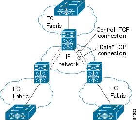
Figure 37-1 FCIP Scenarios
•
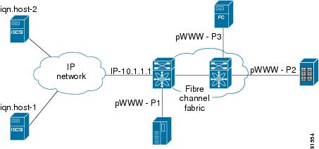
Figure 37-2 iSCSI Scenarios
Module Status Verification
After inserting the module, verify the status of the module using the show module command:
switch# show moduleMod Ports Module-Type Model Status--- ----- -------------------------------- ------------------ ------------1 0 Caching Services Module DS-X9560-SMAP ok2 8 IP Storage Services Module DS-X9308-SMIP ok <-------IPS-8 module4 16 2x1GE IPS, 14x1/2Gbps FC Module DS-X9216i-K9-SUP ok <-------MPS-14/2 module5 0 Supervisor/Fabric-1 DS-X9530-SF1-K9 active *6 0 Supervisor/Fabric-1 DS-X9530-SF1-K9 ha-standby9 4 IP Storage Services Module DS-X9304-SMIP ok <---------IPS-4 moduleMod Sw Hw World-Wide-Name(s) (WWN)--- ----------- ------ --------------------------------------------------1 2.0(1) 0.201 20:41:00:0b:fd:44:68:c0 to 20:48:00:0b:fd:44:68:c02 2.0(1) 0.201 20:41:00:0b:fd:44:68:c0 to 20:48:00:0b:fd:44:68:c04 2.0(1) 0.201 20:c1:00:05:30:00:07:1e to 20:d0:00:05:30:00:07:1e5 2.0(1) 0.0 --6 2.0(1) 0.0 --9 2.0(1) 0.1 22:01:00:05:30:00:07:1e to 22:04:00:05:30:00:07:1eMod Application Image Description Application Image Version-------- ----------------------------- -------------------------1 svc-node1 1.3(5M)1 svc-node2 1.3(5M)Mod MAC-Address(es) Serial-Num--- -------------------------------------- ----------1 00-05-30-01-49-c2 to 00-05-30-01-4a-46 JAB073907EP2 00-05-30-00-9d-d2 to 00-05-30-00-9d-de JAB064605a24 00-05-30-01-7f-32 to 00-05-30-01-7f-38 JAB081405AM5 00-05-30-00-2c-4e to 00-05-30-00-2c-52 JAB06350B1M6 00-05-30-00-19-66 to 00-05-30-00-19-6a JAB073705GL9 00-0d-bc-2f-d6-00 to 00-0d-bc-2f-d6-08 JAB080804TN* this terminal sessionIPS Module Upgrade
Caution
IPS modules use a rolling upgrade install mechanism where each module in a given switch can only be upgraded in sequence. To guarantee a stable state, each IPS module in a switch requires a 5-minute delay before the next IPS module is upgraded.
MPS-14/2 Module Upgrade
Caution
The MPS-14/2 modules have 14 Fibre Channel ports (nondisruptive upgrade) and 2 Gigabit Ethernet ports (disruptive upgrade). MPS-14/2 modules use a rolling upgrade install mechanism for the two Gigabit Ethernet ports where each module in a given switch can only be upgraded in sequence. To guarantee a stable state, each MPS-14/2 module in a switch requires a 5-minute delay before the next module is upgraded.
Supported Hardware
You can configure the FCIP and iSCSI features using one of more of the following hardware:
•
•
Note
•
Configuring Gigabit Ethernet Interfaces
Both FCIP and iSCSI rely on TCP/IP for network connectivity. On each IPS module or MPS-14/2 module, connectivity is provided in the form of Gigabit Ethernet interfaces that are appropriately configured. This section covers the steps required to configure IP for subsequent use by FCIP and iSCSI.
Note
A new port mode, called IPS, is defined for Gigabit Ethernet ports on each IPS module or MPS-14/2 module. IP storage ports are implicitly set to IPS mode, so it can only be used to perform iSCSI and FCIP storage functions. IP storage ports do not bridge Ethernet frames or route other IP packets.
Each IPS port represents a single virtual Fibre Channel host in the Fibre Channel SAN. All the iSCSI hosts connected to this IPS port are merged and multiplexed via the single Fibre Channel host.
In large scale iSCSI deployments where the Fibre Channel storage subsystems require explicit LUN access control for every host device, use of proxy-initiator mode simplifies the configuration.
Note
Tip
Basic Gigabit Ethernet Configuration
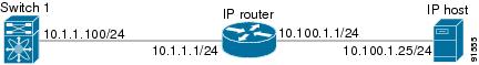
Figure 37-3 shows an example of a basic Gigabit Ethernet configuration.
Figure 37-3 Gigabit Ethernet Configuration Example
Note
To configure the Gigabit Ethernet interface for the example in Figure 37-3, follow these steps:
Configuring Interface Descriptions
See the "Interface Descriptions" section on page 11-12 for details on configuring the switchport description for any interface.
Configuring Beacon Mode
See the "Beacon Mode" section on page 11-17 for details on configuring the beacon mode for any interface.
Configuring Auto-Negotiation
By default, auto-negotiation is enabled all Gigabit Ethernet interface. You can enable or disable auto-negotiation for a specified Gigabit Ethernet interface. When auto-negotiation is enabled, the port automatically detects the speed or pause method, and duplex of incoming signals based on the link partner. You can also detect link up conditions using the auto-negotiation feature.
To configure auto-negotiation, follow these steps:
Configuring the MTU Frame Size
You can configure the interfaces on a switch to transfer large (or jumbo) frames on a port. The default IP maximum transmission unit (MTU) frame size is 1500 bytes for all Ethernet ports. By configuring jumbo frames on a port, the MTU size can be increased up to 9000 bytes.
Note
Tip
You do not need to explicitly issue the shutdown and no shutdown commands.
To configure the MTU frame size, follow these steps:
Configuring Promiscuous Mode
You can enable or disable promiscuous mode on a specific Gigabit Ethernet interface. By enabling the promiscuous mode, the Gigabit Ethernet interface receives all the packets and the software then filters and discards the packets that are not destined for that Gigabit Ethernet interface.
To configure the promiscuous mode, follow these steps:
About VLANs for Gigabit Ethernet
Virtual LANs (VLANs) create multiple virtual Layer 2 networks over a physical LAN network. VLANs provide traffic isolation, security, and broadcast control.
Gigabit Ethernet ports automatically recognize Ethernet frames with IEEE 802.1Q VLAN encapsulation. If you need to have traffic from multiple VLANs terminated on one Gigabit Ethernet port, configure subinterfaces—one for each VLAN.
Note
- The Ethernet switch port connected to the IPS module or MPS-14/2 module is configured as a trunking port.
- The encapsulation is set to 802.1Q and not ISL, which is the default.Use the VLAN ID as a subscription to the Gigabit Ethernet interface name to create the subinterface name (the <slot-number>/<port-number>.<VLAN-ID>).
Configuring the VLAN Subinterface
To configure a VLAN subinterface (VLAN ID), follow these steps:
Interface Subnet Requirements
Gigabit Ethernet interfaces (major), subinterfaces (VLAN ID), and management interfaces (mgmt 0) can be configured in the same or different subnet depending on the configuration (see Table 37-1).
Note
Configuring Static IP Routing
To configure static IP routing (see Figure 37-3) through the Gigabit Ethernet interface, follow these steps:
Displaying the IP Route Table
The show ips ip route interface command takes the Gigabit Ethernet interface as a parameter and returns the route table for the interface. See Example 37-1.
Example 37-1 Displays the IP Route Table
switch# show ips ip route interface gig 8/1Codes: C - connected, S - staticNo default gatewayC 10.1.3.0/24 is directly connected, GigabitEthernet8/1Connected (C) identifies the subnet in which the interface is configured (directly connected to the interface). Static (S) identifies the static routes that go through the router.
Verifying Gigabit Ethernet Connectivity
Once the Gigabit Ethernet interfaces are connected with valid IP addresses, verify the interface connectivity on each switch. Ping the IP host using the IP address of the host to verify that the static IP route is configured correctly.
Note
- The IP address for the destination (IP host) is correctly configured.
- The host is active (powered on).
- The IP route is configured correctly.
- The IP host has a route to get to the Gigabit Ethernet interface subnet.
- The Gigabit Ethernet interface is in the up state.Use the ping command to verify the Gigabit Ethernet connectivity (see Example 37-2). The ping command sends echo request packets out to a remote device at an IP address that you specify (see the "Using the ping Command" section on page 2-14).
Use the show interface gigabitethernet command to verify if the Gigabit Ethernet interface is up.
Example 37-2 Verifying Gigabit Ethernet Connectivity
switch# ping 10.100.1.25PING 10.100.1.25 (10.100.1.25): 56 data bytes64 bytes from 10.100.1.25: icmp_seq=0 ttl=255 time=0.1 ms64 bytes from 10.100.1.25: icmp_seq=1 ttl=255 time=0.1 ms64 bytes from 10.100.1.25: icmp_seq=2 ttl=255 time=0.1 ms--- 10.100.1.25 ping statistics ---3 packets transmitted, 3 packets received, 0% packet lossround-trip min/avg/max = 0.1/0.1/0.1 msGigabit Ethernet IP-ACL Guidelines
Tip
Follow these guidelines when configuring IP-ACLs for Gigabit Ethernet interfaces:
•
Note
•
•
–
–
–
Applying IP-ACLs on Gigabit Ethernet Interfaces
To apply an IP-ACL on an Gigabit Ethernet interface, follow these steps:
Displaying ARP Caches
You can display the ARP cache on Gigabit Ethernet interfaces.
Note
Use the show ips arp interface gigabitethernet command to display the ARP cache on the Gigabit Ethernet interfaces. This command takes the Ethernet interface as a parameter and returns the ARP cache for that interface. See Example 37-3.
Example 37-3 Displays ARP Caches
switch# show ips arp interface gigabitethernet 7/1Protocol Address Age (min) Hardware Addr Type InterfaceInternet 20.1.1.5 3 0005.3000.9db6 ARPA GigabitEthernet7/1Internet 20.1.1.10 7 0004.76eb.2ff5 ARPA GigabitEthernet7/1Internet 20.1.1.11 16 0003.47ad.21c4 ARPA GigabitEthernet7/1Internet 20.1.1.12 6 0003.4723.c4a6 ARPA GigabitEthernet7/1Internet 20.1.1.13 13 0004.76f0.ef81 ARPA GigabitEthernet7/1Internet 20.1.1.14 0 0004.76e0.2f68 ARPA GigabitEthernet7/1Internet 20.1.1.15 6 0003.47b2.494b ARPA GigabitEthernet7/1Internet 20.1.1.17 2 0003.479a.b7a3 ARPA GigabitEthernet7/1...Clearing ARP Caches
The ARP cache can be cleared in two ways: clearing just one entry or clearing all entries in the ARP cache.
Use the clear ips arp command to clear the ARP cache. See Example 37-4 and Example 37-5.
Example 37-4 Clearing One ARP Cache Entry
switch# clear ips arp address 10.2.2.2 interface gigabitethernet 8/7arp clear successfulExample 37-5 Clearing All ARP Cache Entries
switch# clear ips arp interface gigabitethernet 8/7arp clear successfulDisplaying Statistics
This section provides examples to verify Gigabit Ethernet and TCP/IP statistics on the IP storage ports.
Displaying Gigabit Ethernet Interface Statistics
Use the show interface Gigabit Ethernet command on each switch to verify that the interfaces are up and functioning as desired. See Example 37-6.
Example 37-6 Displays the Gigabit Ethernet Interface
switch# show interface gigabitethernet 8/1GigabitEthernet8/1 is up <-----------The interface is in the up state.Hardware is GigabitEthernet, address is 0005.3000.a98eInternet address is 10.1.3.1/24MTU 1500 bytes, BW 1000000 KbitPort mode is IPSSpeed is 1 GbpsBeacon is turned off5 minutes input rate 744 bits/sec, 93 bytes/sec, 1 frames/sec5 minutes output rate 0 bits/sec, 0 bytes/sec, 0 frames/sec3343 packets input, 406582 bytes0 multicast frames, 0 compressed0 input errors, 0 frame, 0 overrun 0 fifo8 packets output, 336 bytes, 0 underruns0 output errors, 0 collisions, 0 fifo0 carrier errorsExample 37-7 Displays the Gigabit Ethernet Subinterface
switch# show interface gigabitethernet 4/2.100GigabitEthernet4/2.100 is upHardware is GigabitEthernet, address is 0005.3000.abcbInternet address is 10.1.2.100/24MTU 1500 bytes5 minutes input rate 0 bits/sec, 0 bytes/sec, 0 frames/sec5 minutes output rate 0 bits/sec, 0 bytes/sec, 0 frames/sec0 packets input, 0 bytes0 multicast frames, 0 compressed0 input errors, 0 frame, 0 overrun 0 fifo1 packets output, 46 bytes, 0 underruns0 output errors, 0 collisions, 0 fifo0 carrier errorsDisplaying Ethernet MAC Statistics
The show ips stats mac interface gigabitethernet command takes the main Gigabit Ethernet interface as a parameter and returns Ethernet statistics for that interface. See Example 37-8.
Note
Example 37-8 Displays Ethernet MAC Statistics
switch# show ips stats mac interface gigabitethernet 8/1Ethernet MAC statistics for port GigabitEthernet8/1Hardware Transmit Counters237 frame 43564 bytes0 collisions, 0 late collisions, 0 excess collisions0 bad frames, 0 FCS error, 0 abort, 0 runt, 0 oversizeHardware Receive Counters427916 bytes, 3464 frames, 0 multicasts, 3275 broadcasts0 bad, 0 runt, 0 CRC error, 0 length error0 code error, 0 align error, 0 oversize errorSoftware Counters3429 received frames, 237 transmit frames0 frames soft queued, 0 current queue, 0 max queue0 dropped, 0 low memoryDisplaying DMA-Bridge Statistics
You can display direct memory access (DMA) device statistics using the show ips stats dma-bridge interface gigabitethernet command. This command takes the main Gigabit Ethernet interface as a parameter and returns DMA bridge statistics for that interface. See Example 37-9.
Note
Example 37-9 Displays DMA-Bridge Statistics
switch# show ips stats dma-bridge interface gigabitethernet 7/1Dma-bridge ASIC Statistics for port GigabitEthernet7/1Hardware Egress Counters231117 Good, 0 bad protocol, 0 bad header cksum, 0 bad FC CRCHardware Ingress Counters218255 Good, 0 protocol error, 0 header checksum error0 FC CRC error, 0 iSCSI CRC error, 0 parity errorSoftware Egress Counters231117 good frames, 0 bad header cksum, 0 bad FIFO SOP0 parity error, 0 FC CRC error, 0 timestamp expired error0 unregistered port index, 0 unknown internal type0 RDL ok, 0 RDL drop (too big), 0 RDL ttl_13656368645 idle poll count, 0 loopback, 0 FCC PQ, 0 FCC EQFlow Control: 0 [0], 0 [1], 0 [2], 0 [3]Software Ingress Counters218255 Good frames, 0 header cksum error, 0 FC CRC error0 iSCSI CRC error, 0 descriptor SOP error, 0 parity error0 frames soft queued, 0 current Q, 0 max Q, 0 low memory0 out of memory drop, 0 queue full drop0 RDL ok, 0 RDL drop (too big)Flow Control: 0 [0], 0 [1], 0 [2], 0 [3]This output shows all Fibre Channel frames that ingress or egress from the Gigabit Ethernet port.
Displaying TCP/IP Statistics
Use the show ips stats ip interface gigabitethernet to display and verify IP statistics. This command takes the main Ethernet interface as a parameter and returns the IP statistics for that interface. See Example 37-10.
Note
Example 37-10 Displays IP Statistics
switch# show ips stats ip interface gigabitethernet 4/1Internet Protocol Statistics for port GigabitEthernet4/1168 total received, 168 good, 0 error0 reassembly required, 0 reassembled ok, 0 dropped after timeout371 packets sent, 0 outgoing dropped, 0 dropped no route0 fragments created, 0 cannot fragmentUse the show ips stats tcp interface gigabitethernet to display and verify TCP statistics. This command takes the main Ethernet interface as a parameter, and shows TCP stats along with the connection list and TCP state. The detail option shows all information maintained by the interface. See Example 37-11 and Example 37-12.
Example 37-11 Displays TCP Statistics
switch# show ips stats tcp interface gigabitethernet 4/1TCP Statistics for port GigabitEthernet4/1Connection Stats0 active openings, 3 accepts0 failed attempts, 12 reset received, 3 establishedSegment stats163 received, 355 sent, 0 retransmitted0 bad segments received, 0 reset sentTCP Active ConnectionsLocal Address Remote Address State Send-Q Recv-Q0.0.0.0:3260 0.0.0.0:0 LISTEN 0 0Example 37-12 Displays Detailed TCP Statistics
switch# show ips stats tcp interface gigabitethernet 4/1 detailTCP Statistics for port GigabitEthernet4/1TCP send stats355 segments, 37760 bytes222 data, 130 ack only packets3 control (SYN/FIN/RST), 0 probes, 0 window updates0 segments retransmitted, 0 bytes0 retransmitted while on ethernet send queue, 0 packets split0 delayed acks sentTCP receive stats163 segments, 114 data packets in sequence, 6512 bytes in sequence0 predicted ack, 10 predicted data0 bad checksum, 0 multi/broadcast, 0 bad offset0 no memory drops, 0 short segments0 duplicate bytes, 0 duplicate packets0 partial duplicate bytes, 0 partial duplicate packets0 out-of-order bytes, 1 out-of-order packets0 packet after window, 0 bytes after window0 packets after close121 acks, 37764 ack bytes, 0 ack toomuch, 4 duplicate acks0 ack packets left of snd_una, 0 non-4 byte aligned packets8 window updates, 0 window probe30 pcb hash miss, 0 no port, 0 bad SYN, 0 paws dropsTCP Connection Stats0 attempts, 3 accepts, 3 established3 closed, 2 drops, 0 conn drops0 drop in retransmit timeout, 1 drop in keepalive timeout0 drop in persist drops, 0 connections drainedTCP Miscellaneous Stats115 segments timed, 121 rtt updated0 retransmit timeout, 0 persist timeout12 keepalive timeout, 11 keepalive probesTCP SACK Stats0 recovery episodes, 0 data packets, 0 data bytes0 data packets retransmitted, 0 data bytes retransmitted0 connections closed, 0 retransmit timeoutsTCP SYN Cache Stats15 entries, 3 connections completed, 0 entries timed out0 dropped due to overflow, 12 dropped due to RST0 dropped due to ICMP unreach, 0 dropped due to bucket overflow0 abort due to no memory, 0 duplicate SYN, 0 no-route SYN drop0 hash collisions, 0 retransmittedTCP Active ConnectionsLocal Address Remote Address State Send-Q Recv-Q0.0.0.0:3260 0.0.0.0:0 LISTEN 0 0Use the show ips stats icmp interface gigabitethernet to display and verify IP statistics. This command takes the main Ethernet interface as a parameter and returns the ICMP statistics for that interface. See Example 37-13.
Example 37-13 Displays ICMP Statistics
switch# show ips stats icmp interface gigabitethernet 2/1ICMP Statistics for port GigabitEthernet2/10 ICMP messages received0 ICMP messages dropped due to errorsICMP input histogram0 destination unreachable0 time exceeded0 parameter problem0 source quench0 redirect0 echo request0 echo reply0 timestamp request0 timestamp reply0 address mask request0 address mask replyICMP output histogram0 destination unreachable0 time exceeded0 parameter problem0 source quench0 redirect0 echo request0 echo reply0 timestamp request0 timestamp reply0 address mask request0 address mask replyConfiguring Gigabit Ethernet High Availability
Virtual Router Redundancy Protocol (VRRP) and Ethernet PortChannels are two Gigabit Ethernet features that provide high availability for iSCSI and FCIP services.
VRRP for iSCSI and FCIP Services
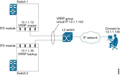
VRRP provides a redundant alternate path to the Gigabit Ethernet port for iSCSI and FCIP services. VRRP provides IP address fail over protection to an alternate Gigabit Ethernet interface so the IP address is always available (see Figure 37-4).
Figure 37-4 VRRP Scenario
In Figure 37-4, all members of the VRRP group must be IP storage Gigabit Ethernet ports. VRRP group members can be one or more of the following interfaces:
•
•
•
•
•
See the "The Virtual Router Redundancy Protocol" section on page 36-16.
Configuring VRRP for Gigabit Ethernet Interfaces
To configure VRRP for Gigabit Ethernet interfaces, follow these steps:
Note
About Ethernet PortChannel Aggregation
Ethernet PortChannels refer to the aggregation of multiple physical Gigabit Ethernet interfaces into one logical Ethernet interface to provide link redundancy and, in some cases, higher aggregated bandwidth and load balancing.
An Ethernet switch connecting to the MDS switch Gigabit Ethernet port can implement load balancing based on the IP address, IP address and UDP/TCP port number, or MAC address. Due to the load balancing scheme, the data traffic from one TCP connection is always sent out on the same physical Gigabit Ethernet port of an Ethernet PortChannel. For the traffic coming to the MDS, an ethernet switch can implement load balancing based on its IP address, its source-destination MAC address, or its IP address and port. The data traffic from one TCP connection always travels on the same physical links. To make use of both ports for the outgoing direction, multiple TCP connections are required.
All FCIP data traffic for one FCIP link is carried on one TCP connection. Consequently, the aggregated bandwidth is 1 Gbps for that FCIP link.
Note
Ethernet PortChannels can only aggregate two physical interfaces that are adjacent to each other on a given IPS module (see Figure 37-5).
Note
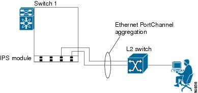
Figure 37-5 Ethernet PortChannel Scenario
In Figure 37-5, Gigabit Ethernet ports 3 and 4 in slot 9 are aggregated into an Ethernet PortChannel. Ethernet PortChannels are not supported on MPS-14/2 modules and 9216i IPS modules.
Note
Configuring Ethernet PortChannels
The PortChannel configuration specified in Chapter 13, "Configuring PortChannels" also applies to Ethernet PortChannel configurations.
To configure Ethernet PortChannels, follow these steps:
Note
- The interface already has an IP address assigned.
- The subinterfaces are configured on that interface.
- The interface already has an associated IP-ACL rule and the PortChannel does not.
Configuring CDP
The Cisco Discovery Protocol (CDP) is supported on the management Ethernet interface on the supervisor module and the Gigabit Ethernet interfaces on the IPS module or MPS-14/2 module.
See the "Configuring CDP" section on page 4-32.
IPS Module Core Dumps
IPS core dumps are different from the system's kernel core dumps for other modules. When the IPS module's operating system (OS) unexpectedly resets, it is useful to obtain a copy of the memory image (called a IPS core dump) to identify the cause of the reset. Under that condition, the IPS module sends the core dump to the supervisor module for storage. Cisco MDS switches have two levels of IPS core dumps:
•
Use the show cores command to list these files.
•
Use the system cores tftp: command to configure an external TFTP server to copy the IPS core dump (and other core dumps).
To configure IPS core dumps on the IPS module, follow these steps:
Default Settings
Table 37-2 lists the default settings for Gigabit Ethernet parameters.
Table 37-2 Default Gigabit Ethernet Parameters
IP MTU frame size
1500 bytes for all Ethernet ports
Auto-negotiation
Enabled.
Promiscuous mode
Disabled