Servicing the Cisco UCS X580p PCIe Node

This chapter contains the following topics:

Guidelines and Limitations

While handling or performing field-service procedures on the Cisco UCS X580p PCIe Node follow these general guidelines and limitations. Additional guidelines and limitations are documented throughout this document.

General Guidelines

Take note of the following general safety warnings:


Warning


IMPORTANT SAFETY INSTRUCTIONS

Before you work on any equipment, be aware of the hazards involved with electrical circuitry and be familiar with standard practices for preventing accidents. Read the installation instructions before using, installing, or connecting the system to the power source. Use the statement number at the beginning of each warning statement to locate its translation in the translated safety warnings for this device.

SAVE THESE INSTRUCTIONS


Note


You are strongly advised to read the safety instruction before using the product.

https://www.cisco.com/web/JP/techdoc/pldoc/pldoc.html

When installing the product, use the provided or designated connection cables/power cables/AC adapters.

〈製品使用における安全上注意〉

www.cisco.com/web/JP/techdoc/index.html

続ケーブル、電源コードセットACアダプタバッテリなどの部品、必添付品または

指定品をご使用ください。添付品指定品以外をご使用になると故障動作不良、火災

原因となりますまた、電源コードセットは弊社指定する製品以外機器には使用

できないためご注意ください。

Warning


Blank faceplates and cover panels serve three important functions: they reduce the risk of electric shock and fire, they contain electromagnetic interference (EMI) that might disrupt other equipment, and they direct the flow of cooling air through the chassis. Do not operate the system unless all cards, faceplates, front covers, and rear covers are in place.


Warning


To reduce risk of electric shock or fire, installation of the equipment must comply with local and national electrical codes.


Note


An instructed person is someone who has been instructed and trained by a skilled person and takes the necessary precautions when working with equipment.

A skilled person or qualified personnel is someone who has training or experience in the equipment technology and understands potential hazards when working with equipment.


Warning


Only a skilled person should be allowed to install, replace, or service this equipment. See statement 1089 for the definition of a skilled person.


Warning


Ultimate disposal of this product should be handled according to all national laws and regulations.


PCIe Node Guidelines

  • The Cisco UCS X580p PCIe Node is supported in the Cisco UCS X9508 chassis only. Do not attempt to install the PCIe node in any other UCS server chassis.

  • Each Cisco UCS X580P PCIe Node must be paired with a Cisco X9516 X-Fabric Module, and therefore, has specific configurations based on the compute node.

    While it is possible that PCIe Gen 4 and Gen 5 hardware can interoperate in the same chassis, the devices will negotiate to the slower PCIe Gen 4 speeds, which will reduce performance.

  • The Cisco UCS X580p PCIe Node supports 600W per GPU maximum.

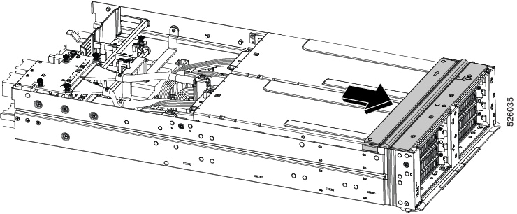
  • Hot removal or insertion of the PCIe node while the host is on is not supported. Before removing the PCIe node, you must properly decommission the M8 compute node(s) associated with the PCIe node.

    Make sure to follow the correct power off procedures as documented for your software management platform, but here is a brief example to help avoid interrupting any in-progress workloads served by the node:

    • Using a Cisco management tool, such as Cisco Intersight, gracefully power down M8 compute nodes that may have been connected to the PCIe node.

    • Ensure that all zones are deleted and all connected nodes are powered down. Doing so ensures that the GPUs are all powered off and can be safely removed and ensure no workloads are interrupted.

    • Verify that the PCIe node's Health Status LED is blinking green, which indicates that the PCIe node is safe to remove. For information about the PCIe node's LEDs, see LEDs.

Serviceable Component Locations

The following image shows the locations of serviceable components on the PCIe node.


Note


The PCIe node has a heatsink next to the rear mezzanine (MEZZ) slot. This heatsink is not serviceable.


Serviceable Component Locations, PCIe Node


Note


Items 3, 4, and 5 are shown for reference. Despite the presence of thumbscrews, none of these components are field-serviceable. Do not attempt to remove or replace them unless explicitly instructed by qualified Cisco personnel.


1

GPU Cage A, with FHFL dual-slot GPU shown

2

GPU Cage 2, with FHFL dual-slot GPU shown

3

Rear Mezzanine Slot

4

Power Entry Board

5

mLOM slot

-

-

Removing the PCIe Node Cover

To remove the cover of the Cisco UCS X580p PCIe Node, follow these steps:

Procedure


Step 1

Press and hold the button down (1).

Step 2

While holding the back end of the cover, slide it back (2), then lift if off of the of node. (3).

By sliding the cover back, you enable the front edge to clear the metal lip on the rear of the PCIe node and enable the catch pins to release from the grooves on the top of the node's sidewalls.


Replacing the PCIe Node Air Baffle

The PCIe node has an air baffle that is located between the GPU cages and the node's rear mezzanine slots. The air baffle is one of the first components you see when you remove the PCIe node's top cover.

The node's air baffle optimizes the airflow from the cold aisle in the datacenter, across the node's components, and exhausts heated air into the hot aisle of the datacenter. When the PCIe node is operating, the air baffle must be installed and the node's top cover must be installed.

To replace the PCIe node's air baffle, use the following topics:

Removing the PCIe Node Air Baffle

The PCIe node's air baffle is a formed plastic component that rests behind the GPU cages. It optimizes airflow for node cooling and ventilation by channeling intake air from the cool aisle and exhausting hot air into the hot aisle.

The air baffle is installed by two captive thumbscrews that mount into threaded standoffs.


Caution


The PCIe node air baffle must be in place, and the node's top cover must be installed for correct airflow. Do not operate the PCIe node without both components correctly installed.


Before you begin

Before attempting this procedure, gather the following tools:

  • A #2 Phillips screwdriver.

  • A T8 Torx screwdriver

Procedure


Step 1

If you have not already removed the node's top cover, do so now.

See Removing the PCIe Node Cover.

Step 2

Loosen the air baffle's screws (1).

  1. Using a T8 Torx screwdriver remove the two screws, one on each side of the node.

    Put the screws somewhere safe. You will use them to reinstall the air baffle.

  2. Using a #2 Phillips screwdriver, loosen the two captive thumbscrews on the top of the air baffle.

Step 3

Grasp the horizontal surfaces of the air baffle and slowly lift it straight up to remove it from the PCIe node (2).

Caution


Be careful when removing the air baffle! Cables are routed through it, and they might cause obstruction on the edges of the air baffle. If you feel any resistance while lifting the air baffle off of the node, check for and clear any obstruction.


Installing the PCIe Node Air Baffle

The PCIe node air baffle is required to ensure optimized air flow and ventilation across the node. You must replace the air baffle after completing any field-service tasks and before installing the node's top cover.

When the PCIe node is shipped, the air baffle is pre-installed at the factory. Use the following task to install the node's air baffle when needed.

Before you begin

Before attempting this procedure, gather a #2 Phillips screwdriver.

Procedure


Step 1

Orient the air baffle so that the captive screws are facing the front of the node.

Step 2

Notice the alignment features, which consist of threaded standoffs for thumbscrews and cutouts for the catch pins on the node (1).

Step 3

Grasp the air baffle by the horizontal edges.

Step 4

Install the air baffle.

  1. Lower the air baffle onto the node, making sure to align the air baffle's thumbscrews with their threaded standoffs on the GPU cages.

  2. When the air baffle is in place, verify that the cutouts on the bottom sides of the baffle are correctly seated in the catch pins on the sheet metal sidewalls of the node.

Step 5

If the baffle is not properly seated, repeat this process until it is.

Step 6

Secure the air baffle to the node.

  1. Using a #2 Phillips screwdriver, tighten the two captive screws on top of the air baffle (3).

  2. Using a T8 Torx screwdriver, insert and tighten the remaining two screws, one on each of the node's sidewalls (3).


Replacing the PCIe Node Front Cover

The PCIe node front cover is a rectangular metal frame that rests on top of the node's faceplate and provides the beveled surface that the top cover slides into.

The front cover accepts seven mounting screws that join to, and attach, the node's faceplate. The front cover is accessible only when the top cover is removed. The node front cover must be removed as part of removing or replacing either of the GPU cages.

Use the following tasks to replace the PCIe node front cover.

Removing the PCIe Node Front Cover

The front cover is secured to the PCIe node by seven screws.

  • Five T8 star-head screws, four across the top of the front cover and one at the top of the middle sheet metal stiffener on the node's faceplate.

  • Two T8 star-head captive thumbscrews, one on each vertical side of the chassis near the top of the node.

Before you begin

Before attempting this procedure, gather a T8 star-head screwdriver.

Procedure


Step 1

If you have not already removed the node's top cover, do so now.

See Removing the PCIe Node Cover.

Step 2

Disconnect the PCIe node.

  1. Using the screwdriver, loosen all seven screws.

    Note


    Although not required, it is a best practice to remove the five screws on the top and front before removing the two thumbscrews on the sides.

  2. Keeping the front cover level, gently slide it toward the back of the node to disconnect it from the node.

Step 3

Detach the front cover from the node.

  1. While sliding the front cover back, check each side to verify that notch on the front cover clears its catch pin on the node's side wall.

  2. When the front cover has released from the catch pin, lift the front cover up to remove it from the node.


Installing the PCIe Node Front Cover

To install the node front cover, you will slide the front cover into place, then reattach the screws.

Before you begin

Before attempting this procedure, gather a T8 star-head screwdriver.

To facilitate proper orientation, the top of the front cover has the word UP printed on it.

Procedure


Step 1

Attach the front cover to the node.

  1. Orient the front cover correctly.

    Make sure the word UP on the front cover is facing up.

  2. Note the location of the notches on each side of the front cover.

  3. Lower the front cover onto the node and make sure that the cover is level.

Step 2

Connect the PCIe node.

  1. Gently slide the front cover toward the front of the node, while checking each side to verify that the notch on the front cover engages its catch pin on the node's side walls.

  2. Using the screwdriver, tighten all seven screws, four across the top, one on each side, and one in the front.

    Note


    Although not required, it is a best practice to install the two thumbscrews on the sides before installing screws on the top and front.


Replacing GPU Cages

Each PCIe node has two GPU cages, which mount to the PCIe node sheet metal and contain the GPUs. One type of GPU cage is supported that accepts FHFL dual-slot GPUs. GPU cages rest directly on the PCIe node in two slots.

GPU cages are interchangeable, so you can install a GPU cage in either slot A or slot B. Even though GPU cages are interchangeable, it is a best practice to replace the cages in the same slots where they were originally located. Replacing the cages in the same location (cage A replaced in cage slot A and cage B replaced in cage slot B) facilitates reassembly especially related to cable routing.


Note


The PCIe node's GPU cages support PCIe Gen 5 connectivity. Cisco offers similar GPU cages for Gen 4 connectivity through a similar product, the Cisco UCS X440p PCIe Node. Gen 4 and Gen 5 GPU cages are not interchangeable, so do not attempt to reuse the GPU cages across these two different products.


PCIe cages are not offered as a spare part. If you need a new PCI cage, contact Cisco to start an RMA for the node.

To replace GPU cages, use the following tasks:

Cable Reference

GPU cages, and the GPUs themselves, use the following cables. The following table summarizes which cables are used by the GPU cages or GPUs themselves as well as where the cables are connected.

Cables

Details

MCIO, 4 per node (two per GPU cage)

Each GPU cage has two MCIO cables. One cable connects the GPU cage to the upper mezzanine card, and one cable connects the GPU cage to the lower mezzanine card.

AUX, up to 4 (one per GPU)

Each GPU has one AUX cable that supplies power to the GPU. One end of the cable connects to the GPU itself, and the other end connects to either of the AUX1 or AUX2 connectors on the node's motherboard.

CEM, 4 per node (two per GPU cage)

Each GPU cage has two cables that supply power to the cage. Both cables connect to the GPU cage at one end, and the other ends connect to the CEM1 and CEM2 connectors on the node's motherboard.

GPU Cage Population Guidelines

Each PCIe node has two GPU cages: Cage A and Cage B. GPU cage identifiers are labeled on the PCIe node so that they are visible when the GPU cages are removed.

Each cage supports a maximum of two FHFL dual-slot GPUs for a total of four GPU slots. Slot identifiers are labeled on the front panel of the node.

When removing and installing GPU cages, be aware of the following:

  • Always populate Cage A before Cage B. If only one cage needs to be populated, it must be Cage A.

  • When populating GPU cages, always do so in ascending numerical order.

    • Populate Cage A slot 1 before Cage A slot 2

    • Populate Cage B slot 3 before Cage B slot 4.

  • Any GPU cage can accept any of the supported GPUs. For example, Cage 1 is not "reserved" for only H200 GPUs.

  • Be aware of the following GPU mixing consideration: GPUs can be mixed across the node, but not within GPU Cages. For example, H200 NVL GPUs can be installed in Cage A, and RTX PRO 6000 GPUs can be installed in Cage B. But, you cannot install a mix of H200 and RTX PRO 6000 GPUs in the same cage.

  • If your deployment requires multiple types of GPUs, install the same types in the same cage.

Removing a GPU Cage

Each PCIe node contains two PCIe GPU cages of the same type. Use this procedure to remove a GPU cage.

Procedure


Step 1

Remove the PCIe node from the server.

See Removing the PCIe Node.

Step 2

Remove the top cover.

See Removing the PCIe Node Cover.

Step 3

Remove the node's air baffle.

See Removing the PCIe Node Air Baffle.

Step 4

Remove the front cover.

See Removing the PCIe Node Front Cover

Step 5

Disconnect the cables.

  1. Grasp the rubber cable retainers and unhook them from the metal tab that secures them.

    When the cable retainers are unhooked, cables will become unbundled. You will find it helpful to flatten the retainers so that they lie flat on the motherboard to prevent obstruction or snagging on other parts.

  2. Grasp the AUX cables and disconnect them from the AUX1 and AUX2 connectors on the node motherboard.

  3. Disconnect the MCIO cables from the rear mezzanine (MEZZ) connector.

    Note


    MCIO cable connectors are stacked vertically on the rear mezz slot. If you're removing both GPU cages at the same time, you'll find it helpful to disconnect the top cable(s) first. Doing so allows easier access to the bottom cables.

  4. Disconnect the power cables from the node's CEM1 and CEM2 motherboard connectors.

Step 6

When MCIO and power cables are disconnected, detach the cages.

  1. Using a #2 Phillips screwdriver, remove the captive screws that secure the cages to the PCIe node's base assembly.

  2. When the thumbscrews are removed, grasp the cages and lift them off of the PCIe node.

    Caution


    If you feel any resistance while removing the cages, reseat the cage and verify that all screws are loose and check for obstructions, such as cables or cable retainers that might be snagged on other components. Proceed when the resistance is no longer present.


Installing a GPU Cage

Use this procedure to install a GPU cage onto the PCIe node.

Before you begin

Before attempting this procedure, gather a #2 Phillips screwdriver.

Procedure


Step 1

Orient the GPU cage with the PCIe node so that the MCIO cables are facing the rear mezzanine module.

Step 2

Attach the GPU cage to the PCIe node.

  1. Before lowering the GPU cage onto the node, observe the two guide holes on the cage and their respective guide pins on the PCIe module and the thumbscrews on the cage and their screw holes on the node (1).

  2. Lower the GPU cage onto the PCIe module (2), making sure that the guide holes on the cage align with the guide pins on the node, and the thumbscrews on the cage align with the screw holes on the node.

    Caution


    While installing the GPU cage, make sure that the cables are not pinched between the GPU cage and the node.

  3. Using a #2 Phillips screwdriver, tighten the captive thumbscrews to secure the GPU cage to the node.

  4. Connect the MCIO cables to the rear mezzanine (MEZZ) connector.

  5. Connect the power cables to the node's CEM1 and CEM2 motherboard connectors.

    Cables connect directly behind their cage, and cable are labeled to identify which cables connect to which plug on the motherboard.

  6. Connect the AUX cables to the AUX1 and AUX2 connectors on the node motherboard.


Replacing a GPU Card

Supported GPU cards are contained in the GPU cage during normal operation. For more information, see GPU Cage Options.

The PCIe node supports only full height, full length (FHFL) dual-slot GPUs. For more information, see Supported GPUs.

To replace a GPU card, use the following tasks:

GPU Replacement Guidelines and Limitations

Be aware of the following guidelines and limitations for replacing FHFL dual-slot GPUs.

  • For installing GPUs into a GPU cage

    • It is a best practice to populate slots in ascending order, for example, slot 1 before slot 2 in the same GPU cage. For information about how slots are numbered in each GPU cage, see Slot Numbering.

    • Completely populate each GPU cage before starting to populate another.

  • Cisco offers Cisco PCIe blanks (UCSX-PCIF-GPU=) that fill unused GPU slots. If your PCIe node is not fully configured with GPUs, you must install the appropriate number of blanks. For PCIe nodes that are less than fully configured with GPUs, do not operate the PCIe node without a GPU filler blank.

  • For NVIDIA H200 NVL GPUs, it is possible that existing GPUs have a legacy straight extender bracket that is currently incompatible with the GPU cages. In this case, Cisco offers an enhanced extender bracket (EXT-X580P-GPU-N=) to provide optimal physical support for the GPU.

    You must replace the legacy extender bracket with the Cisco enhanced extender bracket. Bracket replacement must be completed before installing, or reinstalling, the H200 NVL GPU. For more information, see Replacing a Legacy GPU Extender Bracket

Replacing a Legacy GPU Extender Bracket

All Cisco-provided GPUs have the correct GPU bracket installed. However, some deployments might use GPUs that were acquired from other vendors than Cisco.

For GPUs acquired from other sources, it is possible that the NVIDIA H200 NVL GPUs are assembled with a legacy straight extender bracket. This straight bracket must be replaced to use H200 NVL GPUs with the PCIe node.

To obtain an enhanced extender bracket (Cisco PID: EXT-X580P-GPU-N=) as the supported replacement part, contact Cisco and order the enhanced extender bracket by PID.

After receiving the enhanced extender bracket, use the following tasks to replace the legacy bracket with the new bracket.

The new bracket must be installed onto the H200 NVL GPU before the GPU is installed into the PCIe node's GPU cage.

Removing the Legacy Extender Bracket

For NVIDIA H200 NVL GPUs only, this procedure enables the GPU to properly fit the GPU cages. For more information, see GPU Replacement Guidelines and Limitations.

Use the following task to remove the legacy straight extender bracket so that you can replace it with the supported Cisco enhanced extender bracket.

Before you begin

Before attempting this procedure, gather a T15 star-head screwdriver.

Procedure

Step 1

Remove the existing NVIDIA H200 NVL GPU.

See Removing a FHFL GPU.

Step 2

Using the screwdriver, remove the two screws that secure the legacy straight extender bracket.

Step 3

Detach the bracket from the GPU.


What to do next

Connect the Cisco replacement bracket. See Installing the Enhanced Extender Bracket.

Installing the Enhanced Extender Bracket

For NVIDIA H200 NVL GPUs only, this procedure enables the GPU to properly fit the PCIe node cages. For more information, see GPU Replacement Guidelines and Limitations.

Use the following task to install the Cisco enhanced extender bracket before installing an H200 NVL GPU into the PCI node's GPU cages.

Before you begin

Before attempting this procedure, gather a T15 star-head screwdriver.

To obtain an enhanced extender bracket (Cisco PID: EXT-X580P-GPU-N=), contact Cisco and order the enhanced extender bracket by PID.

Procedure

Step 1

If you have not already removed the existing H200 NVL GPU, remove it now.

See Removing a FHFL GPU.

Step 2

Attach the Cisco enhanced extender bracket to the GPU.

Step 3

Using the screwdriver, reinsert the two screws that you previously removed.

Step 4

Reinstall the GPU.

See Installing a FHFL GPU.

Removing a FHFL GPU

Full height, full length (FHFL) dual-slot GPUs are supported in either GPU cage. Each GPU cage has two PCIe sockets, each of which can accept one GPU for a maximum of two GPUs in each cage.

Use this task to remove a FHFL GPU.

Before you begin

Before attempting this procedure, gather a #2 Phillips and a T8 star-head screwdriver.

Procedure


Step 1

If you have not already done so remove the GPU cage from the PCIe node.

See Removing a GPU Cage.

Step 2

Grasp the rubber cable retainer and unhook it so that the GPU cables are unbundled (1).

Step 3

Using the T8 screwdriver remove the securing screws that hold the GPU in the slot (2).

Step 4

Disconnect the GPU AUX power cable from the GPU.

Step 5

Using the #2 Phillips screwdriver, loosen the thumbscrews at the front of the GPU cage, which is the end opposite the cables (3).

Step 6

When the Phillips-head screws are loosened, swing the hinged door open so that the GPU can slide out of the slot (1).

Note


If you're installing a GPU for the first time, GPU filler blanks will be present. They must be removed (2).

Step 7

Grasp the GPU, and holding it level, pull it out so that it disconnects from the PCIe socket.

Step 8

Slide the GPU out until it clears the slot in the cage.


What to do next

Reinsert an FHFL GPU. See Installing a FHFL GPU.

Installing a FHFL GPU

Full height, full length (FHFL) dual-slot GPUs install horizontally into the GPU cage so that the GPU's connector seats into the PCIe socket inside the GPU cage.

GPU cages have standard PCIe alignment features, such as a slot in the rear wall that accepts a tab on the GPU, and a horizontal notch on the front wall that accepts the edge of the GPU's extender bracket.

When installing the first GPU, install it in the lowest numbered slot in the GPU cage, slot 1 in GPU cage A or slot 3 in GPU cage B.

Use the following procedure to install a full height full length GPU into GPU cage.

Before you begin

Review the GPU Replacement Guidelines and Limitations. Before attempting this procedure, gather a #2 Phillips and a T8 star-head screwdriver.

Procedure


Step 1

Align the GPU with the slot so that the GPU's golden fingers will meet the PCIe socket.

Step 2

Holding the GPU level, align the front edge of the extender bracket with the notch on the front wall of the GPU cage (1).

Step 3

Slide the GPU into the slot (2), making sure that the tab on the GPU lines up with the correct slot in the rear wall (1).

Step 4

When you feel the connector on the GPU meet the PCIe socket, press the GPU firmly into place to install it.

Step 5

Attach the GPU power cable to the node motherboard.

  1. Route the GPU power cable through the cage and connect it to the GPU.

    Note


    The GPU power cable must be routed behind the corner of the GPU cage to prevent obstruction.

  2. Using the T8 star-head screwdriver, reinsert the screw to secure the GPU into the slot.

  3. Connect the GPU power cable to the AUX1 or AUX2 connector on the motherboard.

    It is a best practice to connect the GPU to the corresponding AUX connector, for example, the GPU in slot 1 should be connected to the AUX1 connector, and the GPU in slot 2 should be connected to the AUX2 connector.

  4. Using the T8 screwdriver, install the securing screw making sure to tighten the screw to a range of 4 to 6 in lbs. of torque.

    Caution


    Do not overtighten! This screw is small and susceptible to shearing or stripping if overtightened. Do not exceed the documented torque specs.

Step 6

(Optional) To install a second GPU:

  1. Align the GPU and slide into place until the GPU's connector is seated into the PCIe socket.

  2. Route the GPU cable through the GPU cage and behind the front corner of the cage.

  3. Connect the GPU power cable to the other AUX connector on the motherboard.

  4. Using the T8 screwdriver, install the securing screw making sure to tighten the screw to a range of 4 to 6 in lbs. of torque.

    Caution


    Do not overtighten! This screw is small and susceptible to shearing or stripping if overtightened. Do not exceed the documented torque specs.

Step 7

Complete the GPU installation.

  1. Verify that the securing screw is installed for each GPU to hold them into the PCIe slot.

  2. Grasp the rubber cable retainers and reconnect them.

  3. Swing the hinged doors closed.

  4. Using the #2 Phillips screwdriver, tighten each of the thumbscrews to secure the GPU(s) into the slot(s).


What to do next

Install the GPU cage. See Installing a GPU Cage.

Installing the PCIe Node Cover

Use this task to install the PCIe node's top cover.

Procedure


Step 1

Align the cutouts on the top cover's sidewalls with the guide pins on the PCIe node's sidewalls (1).

Step 2

Lower and install the cover at an angle so that the cutouts on the rear of the catch the guide pins on the inside walls of the node (2).

Step 3

When the top cover is flush with the PCIe node, keep the top cover flat, and slide it forward until the release button clicks.

Note


Make sure that the front edge of the top cover slides under the metal edge of the node front cover. If you feel resistance, these two edges might be making contact instead of sitting on top of each other.