Recycling the PCB Assemblies
The Cisco UCS X580p PCIe Node has multiple different PCB assemblies (PCBAs), which consist of the PCB motherboard plus any components mounted on it.
For compliance with local e-waste and recycling laws, use the following procedures to disassemble the PCBAs.
Recycling the GPU Cage PCBA
Use the following task to disassemble the GPU cage for recycling.
Before you begin
 Note |
For Recyclers Only! This procedure is not a standard field-service option. This procedure is for recyclers who will be reclaiming the electronics and sheet metal for proper disposal to comply with local eco design and e-waste regulations. |
To remove a GPU cage PCBA, the node must be removed from the chassis.
You will find it helpful to gather a #2 Phillips screwdriver before beginning this procedure.
Procedure
|
Step 1 |
Remove the node's top cover. Go to Removing the PCIe Node Cover. |
|
Step 2 |
Remove the node's air baffle. |
|
Step 3 |
Remove the node's front panel. |
|
Step 4 |
If you have not already removed the GPU cages, remove them now. Go to Removing a GPU Cage. |
|
Step 5 |
If necessary, remove the NVIDIA NVLink GPU interconnect. |
|
Step 6 |
Remove the GPU from the cage as documented in Removing a GPU Cage. |
|
Step 7 |
Remove the PCB from the cage.
|
|
Step 8 |
Dispose of the PCB, components, and sheet metal in compliance with relevant e-waste and recycling laws. |
Recycling the Node PCBA
Each Cisco UCS X580p PCIe Node has a PCBA (motherboard) that is connected to sheet metal. You must disconnect the PCBA from the chassis sheet metal to recycle the PCBA. You will need to disassemble and remove additional parts to gain access to the PCBA.
You will need to recycle the PCBA for each PCIe node.
Use the following procedure to recycle the Cisco UCS X580p PCIe Node's motherboard.
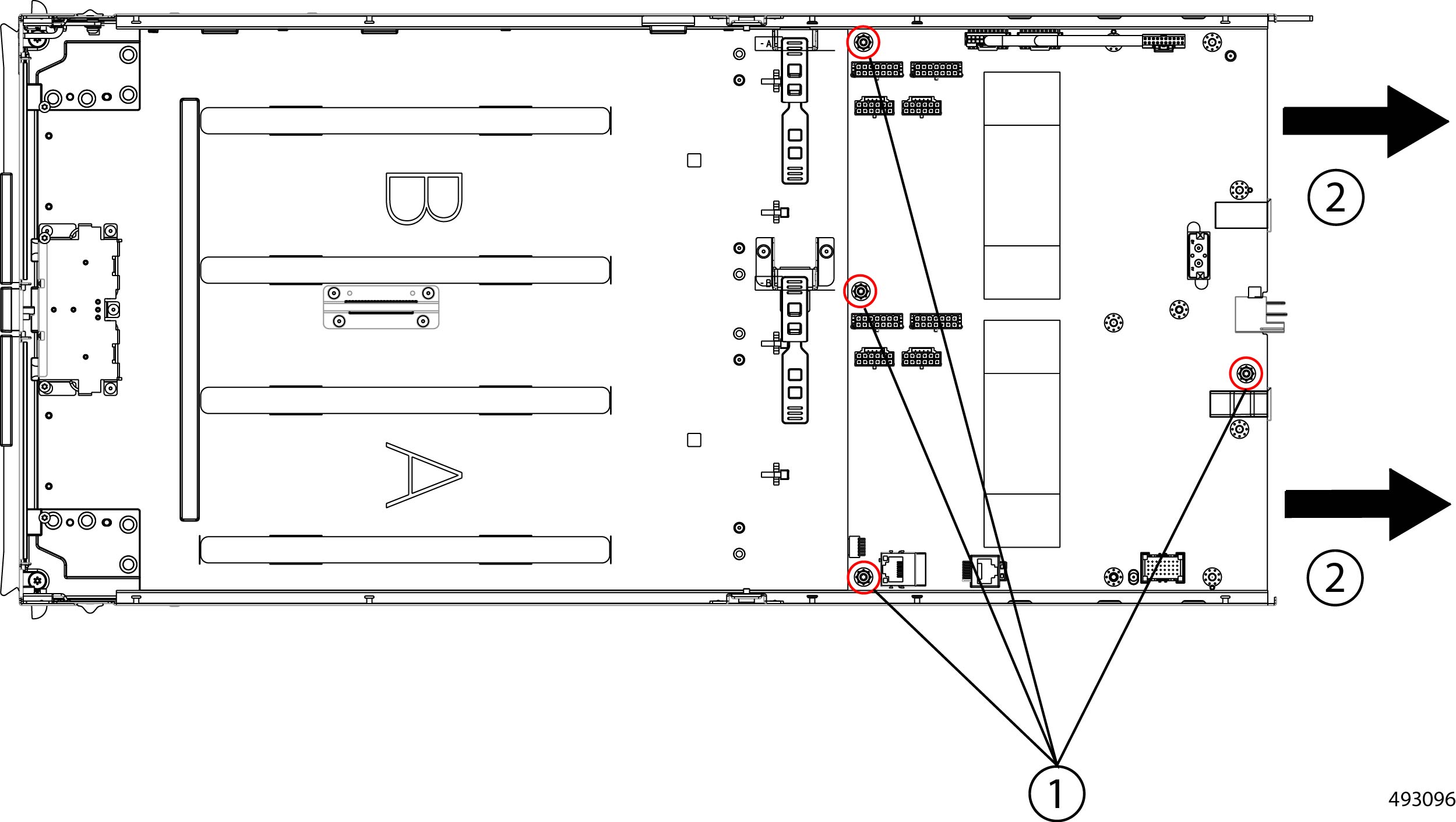
Note |
The following illustrations focus on the rear of the node, which is where the PCB is located. In these illustrations, dashed lines indicate the locations of fasteners present on the node, but not visible in the illustration. |
Before you begin
Note |
For Recyclers Only! This procedure is not a standard field-service option. This procedure is for recyclers who will be reclaiming the electronics and sheet metal for proper disposal to comply with local eco design and e-waste regulations. |
To remove the node's printed circuit board assembly (PCBA) which is the main PCB plus components mounted on it, the node must be removed from the chassis.
You will find it helpful to gather a #2 Phillips, T8 Torx, and T10 Torx screwdriver for this procedure.
The node's PCB is located at the rear of the node. You will find it helpful to remove the GPU cages before attempting this procedure. When the GPU cages are removed, you will have ample space to work on the node's PCB.
Procedure
|
Step 1 |
Remove the node's top cover. Go to Removing the PCIe Node Cover. |
||
|
Step 2 |
If you have not already removed the GPU cages, remove them now. Go to Removing a GPU Cage. |
||
|
Step 3 |
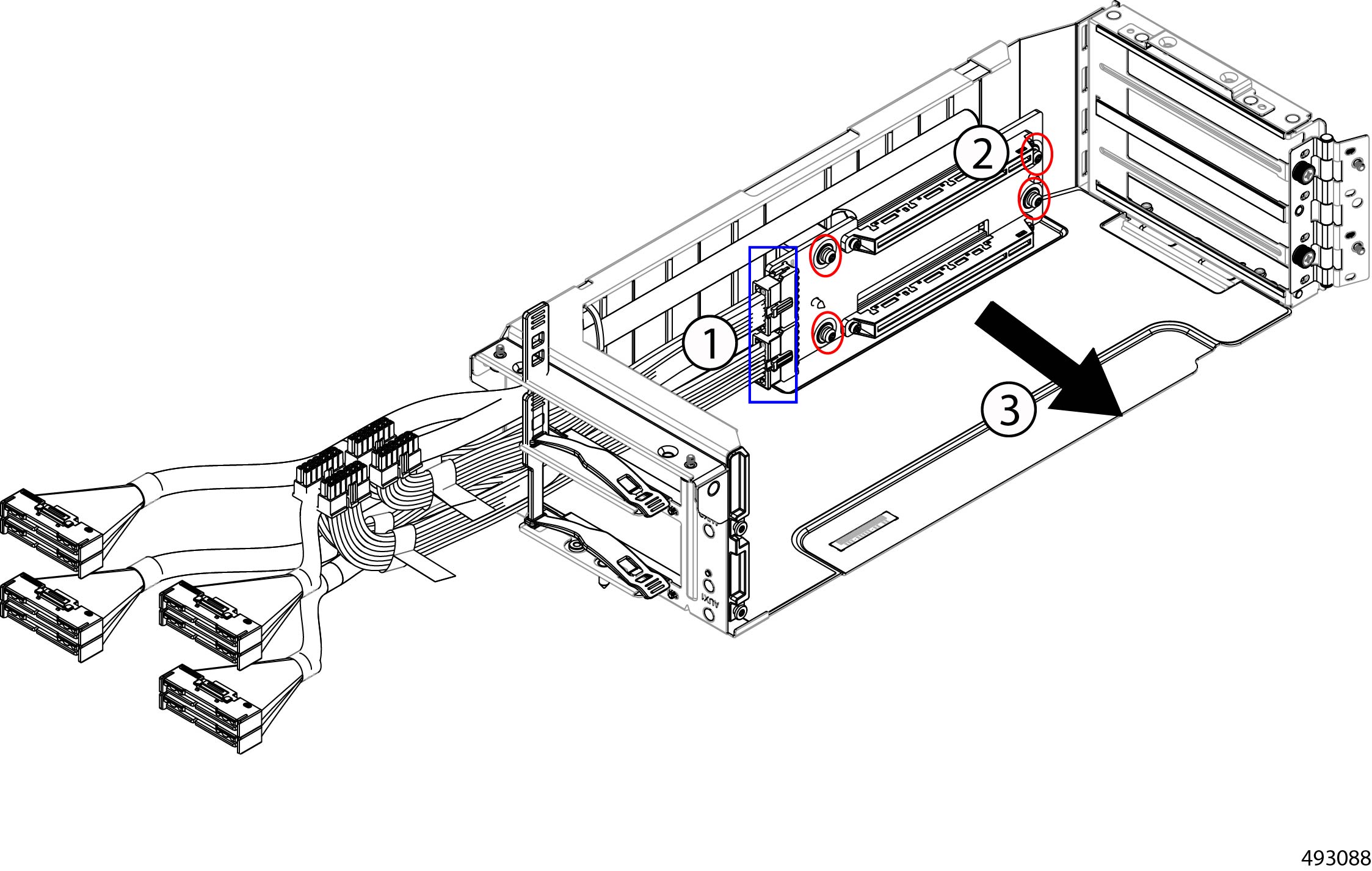
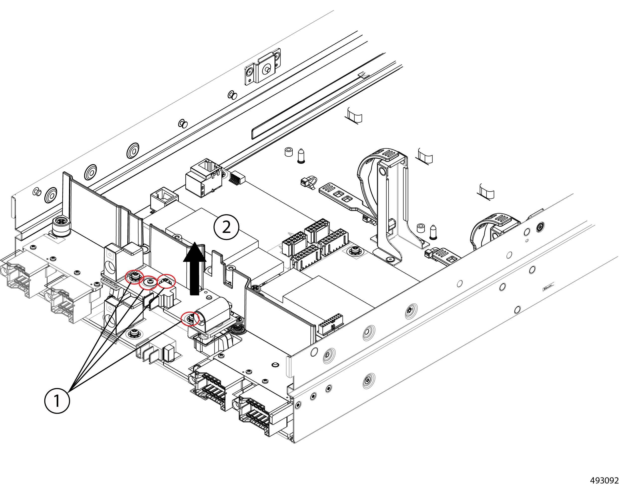
Begin disconnecting the node PCB.
|
||
|
Step 4 |
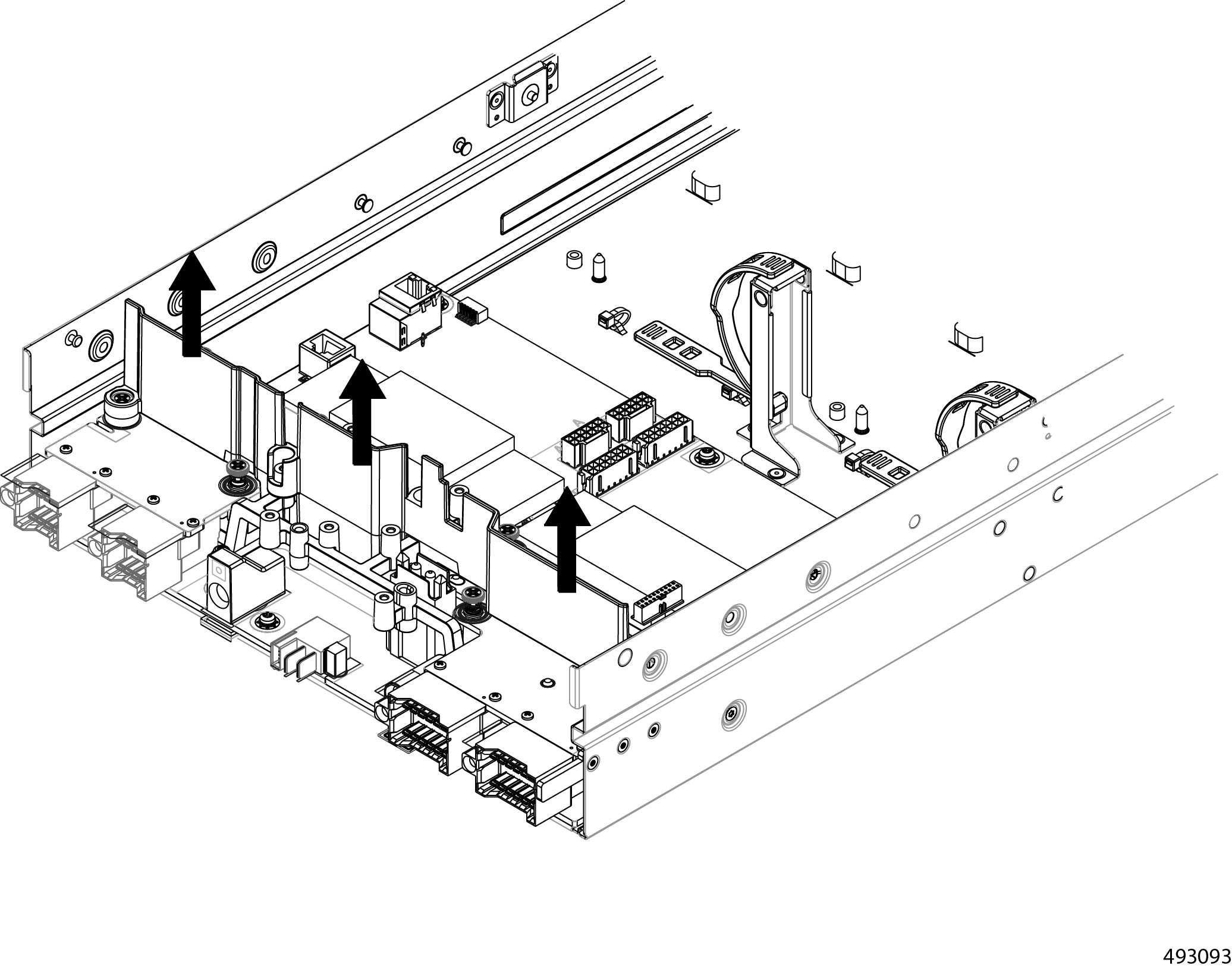
Remove the upper rear mezzanine card.
|
||
|
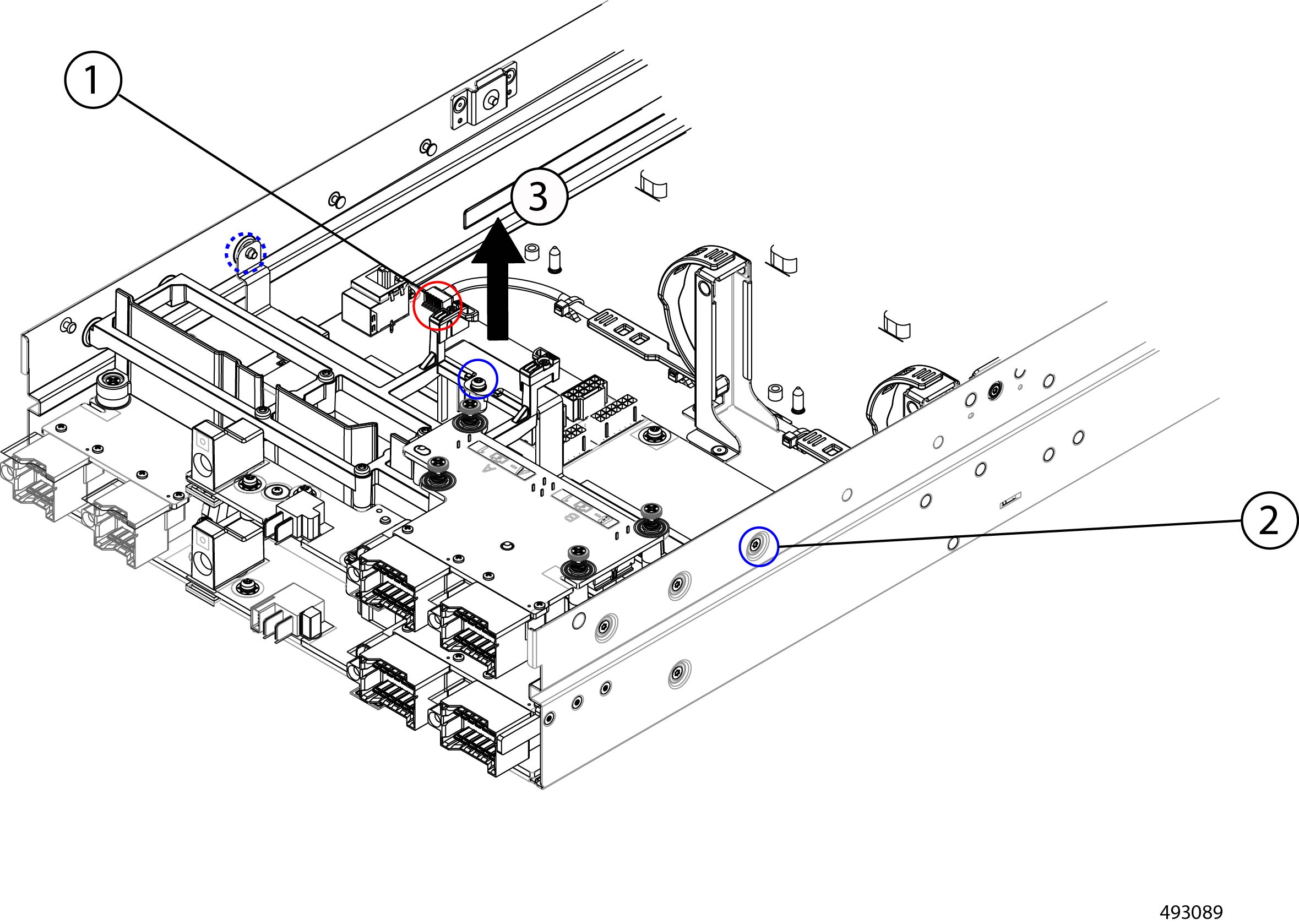
Step 5 |
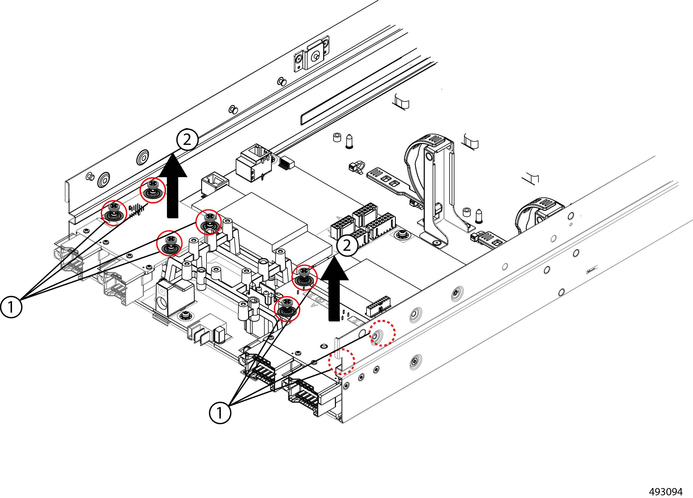
Remove the upper support frame.
|
||
|
Step 6 |
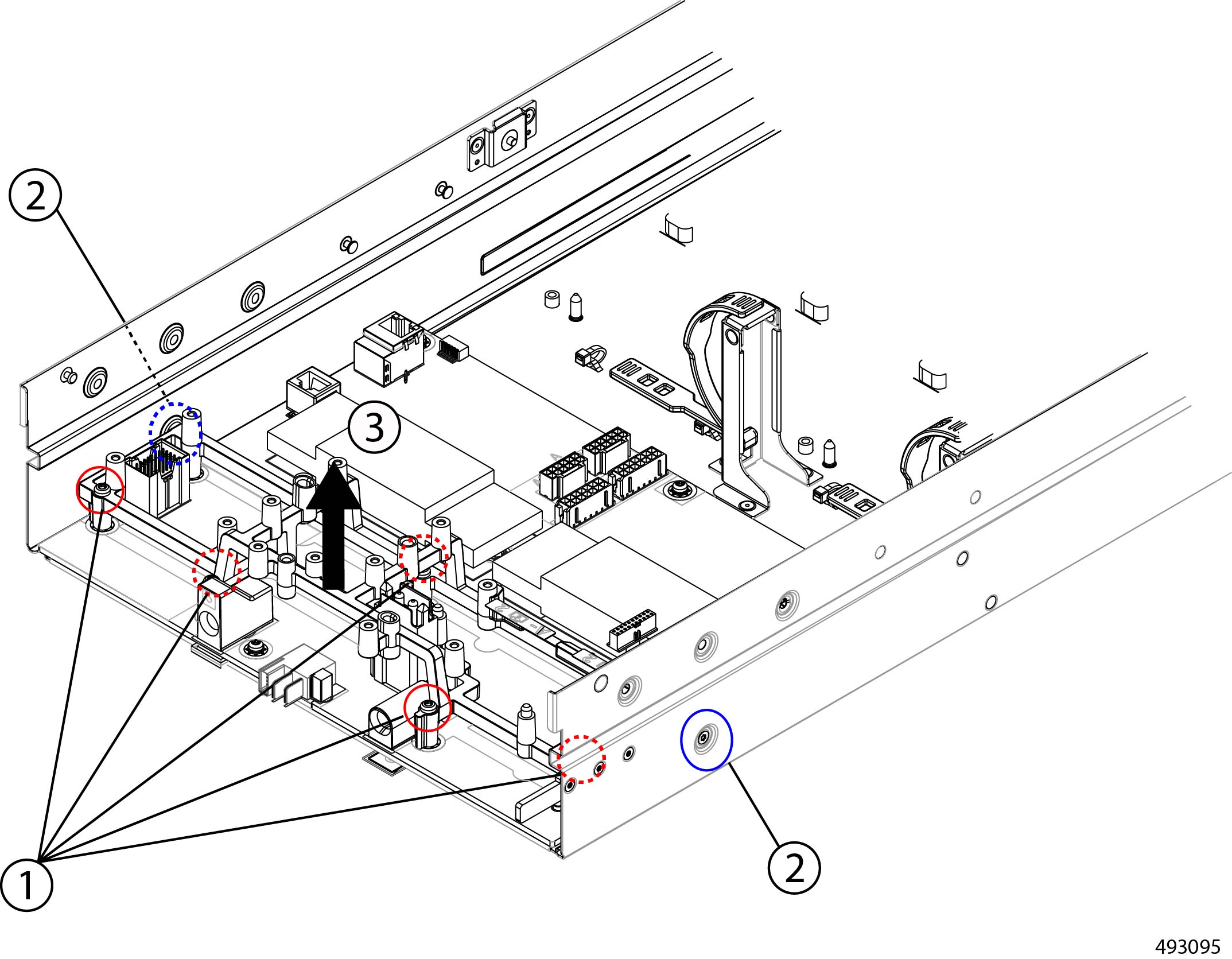
Remove the node power card.
|
||
|
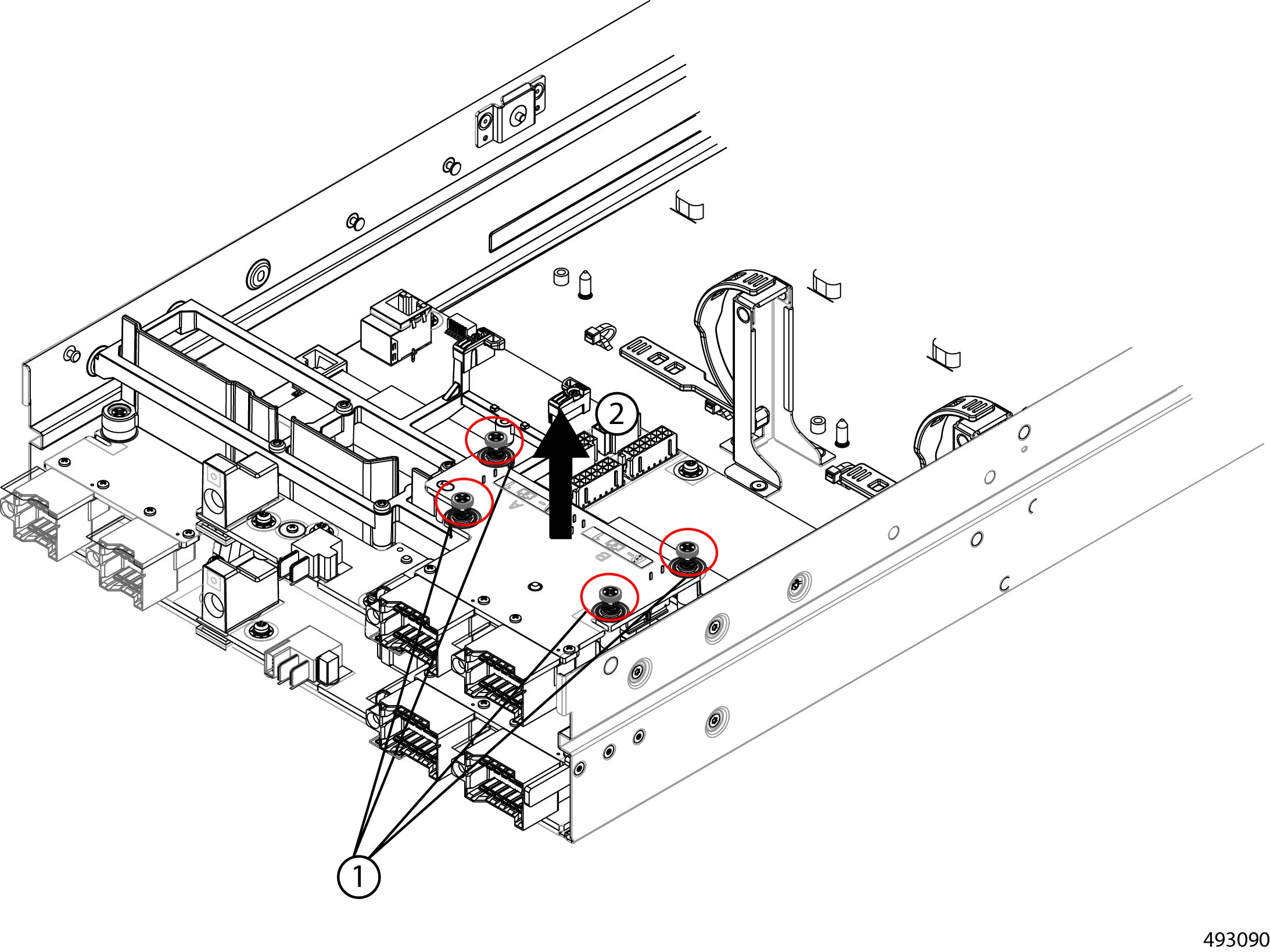
Step 7 |
Grasp the node's air blocker and remove it.
|
||
|
Step 8 |
Remove both of the lower cards.
|
||
|
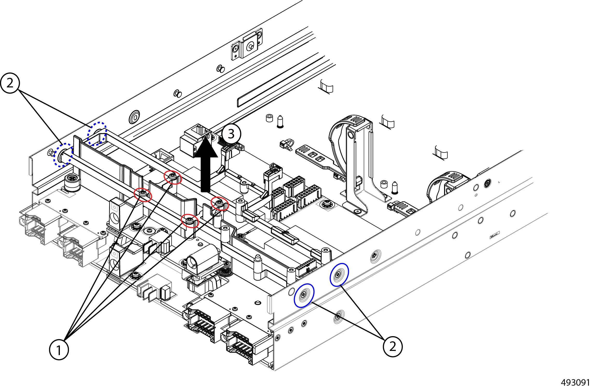
Step 9 |
Remove the lower support frame.
|
||
|
Step 10 |
Detach the node's PCB from the sheet metal tray.
|
||
|
Step 11 |
Dispose of the PCB, components, and sheet metal in compliance with relevant e-waste and recycling laws. |
 Feedback