Overview
The Cisco UCS X580p PCIe Node (UCSX-580P) is the second generation PCIe node that is part of the Cisco UCS X-Fabric system.
The PCIe node pairs with Cisco UCS X-Series M8 compute nodes and Cisco UCS X9516 X-Fabric Modules to support robust workloads that require GPU processing power. The node is designed to work with its related hardware to simplify adding, removing, or upgrading GPUs on compute nodes.
The PCIe node supports PCIe connectivity for a variety of GPUs.
-
GPUs: Four x16 FHFL (full-height, full length) dual slot PCIe cards, zero, one, or two GPUs per GPU cage.

Note
Each PCIe node supports GPUs through two GPU cages. Each PCIe node can be configured with different types of GPUs, but each GPU cage must be configured with the same type of GPU. For example, a PCIe node can support NVIDIA H200 GPUs and NVIDIA L40S GPUs, but each type must be installed in the same GPU cage. For supported GPUs, see Supported GPUs.
-
Host connection between the PCIe mezzanine (MEZZ) and the PCIe node is supported through a PCIe Gen 5 (2 x16) connector in the rear MEZZ slot.
-
GPU cage option, a maximum of two GPU cages is supported in each PCIe node. Each GPU cage supports up to two FHFL dual-slot GPUs.
Front Panel
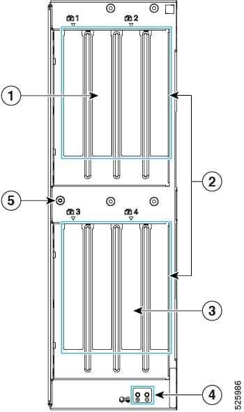
The Cisco UCS X580p PCIe Node is a single PCIe node that occupies two slots in the Cisco UCS X-Series server chassis. Each node is front loading, so it is inserted into, and removed from, the front of the Cisco UCS X9508 chassis.
The following image shows the PCIe node front panel.
|
1 |
PCIe node slots 1 and 2 |
2 |
PCIe node Ejector handles, 2 |
|
3 |
PCIe node slots 3 and 4 |
4 |
PCIe Node Status LEDs. See LEDs. |
|
5 |
Mounting Hole for additional physical features. |
- |
Node Identification
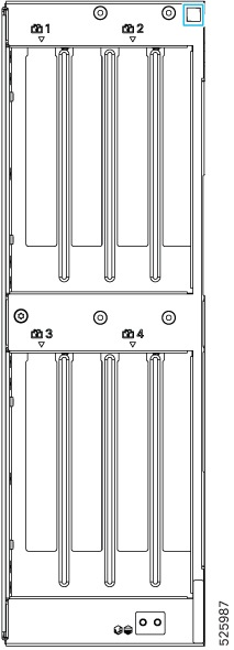
Each Cisco UCS X580p PCIe Node (UCSX-580P) features a product identification QR code at the upper right corner of the node.
-
The Cisco product identifier (PID) or virtual identifier (VID)
-
The product serial number
The node identification QR code applies to the entire PCIe node, not the individual GPUs installed in it.
You will find it helpful to scan the QR code so that the information is available if you need to contact Cisco personnel.
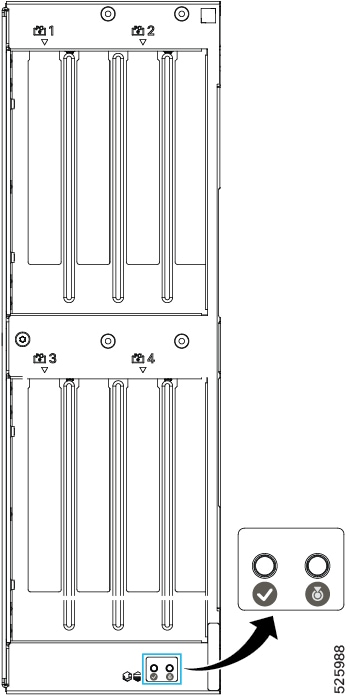
LEDs
The PCIe node front panel has the following LEDs.
|
LED |
Color |
Description |
|---|---|---|
|
PCIe Node Status |
Off |
PCIe node is not powered on/initialized. |
|
Solid Green |
Host is receiving power or the zone is active. |
|
|
Blinking Green (1 Hz) |
Host is powered off. You can safely remove the PCIe node. |
|
|
Solid Amber |
Warning or Fault condition exists, such as a configuration or system or device inventory problem. |
|
|
Blinking Amber (1 Hz) |
Severe fault, such as an insufficient power condition. |
|
|
PCIe Node ID/Locator LED
|
Off |
Locator not enabled. |
|
Blinking Blue (1 Hz) |
Locates a selected PCIe node—If the LED is not blinking, the PCIe node is not selected. You can activate the LED in UCS Intersight, which enables toggling the LED on and off. |
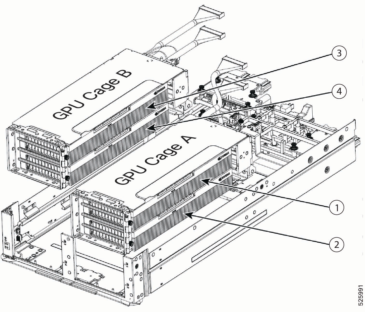
GPU Cage Options
Each PCIe node contains one type of GPU cage that accepts a maximum of two FHFL dual-slot GPUs through two x16 FHFL dual-slot PCIe connectors.
Each GPU cage mounts directly to the PCIe node's sheet metal. GPU cages are identified by their position as either A or B when mounted on the PCIe node. The node has labels, A or B, on the PCIe node under each GPU cage that identify the cages' locations.
Power and signaling are supported by cables that connect each GPU cage to the PCIe node rear mezzanine PCBA.
If your PCIe node is not fully populated, the empty GPU cage must be installed, and the GPU cage itself must have PCIe slot blanks installed when no GPUs are present. For example, if you have a PCIe node with two GPUs in Cage A, but no GPUs in Cage B, Cage B must contain two Cisco PCIe blanks, and it must be installed on the PCIe node even though Cage B is empty.
Slot Numbering
GPU cages and GPU slots have specific identifiers that determine their locations in the PCIe node.
-
For hardware, slot numbering consists of GPU_cage_Identifier/Slot. So, for example, A/1 indicates GPU cage A, slot 1.
-
For Cisco management software, such as Cisco Intersight Managed Mode (IMM), the slot numbering consists of Cage [identifier]-Slot [number]. So, for example, CageA-SLOT1 indicates GPU cage A, slot 1.
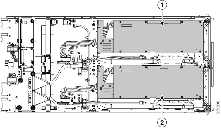
GPU Cage Numbering
|
1 |
GPU cage A GPU cage A is controlled by CPU1 on the Cisco UCS M8 compute node paired with the PCIe node |
2 |
GPU Cage B GPU cage B is controlled by CPU2 on the Cisco UCS M8 compute node paired with the PCIe node |
GPU Slot Numbering
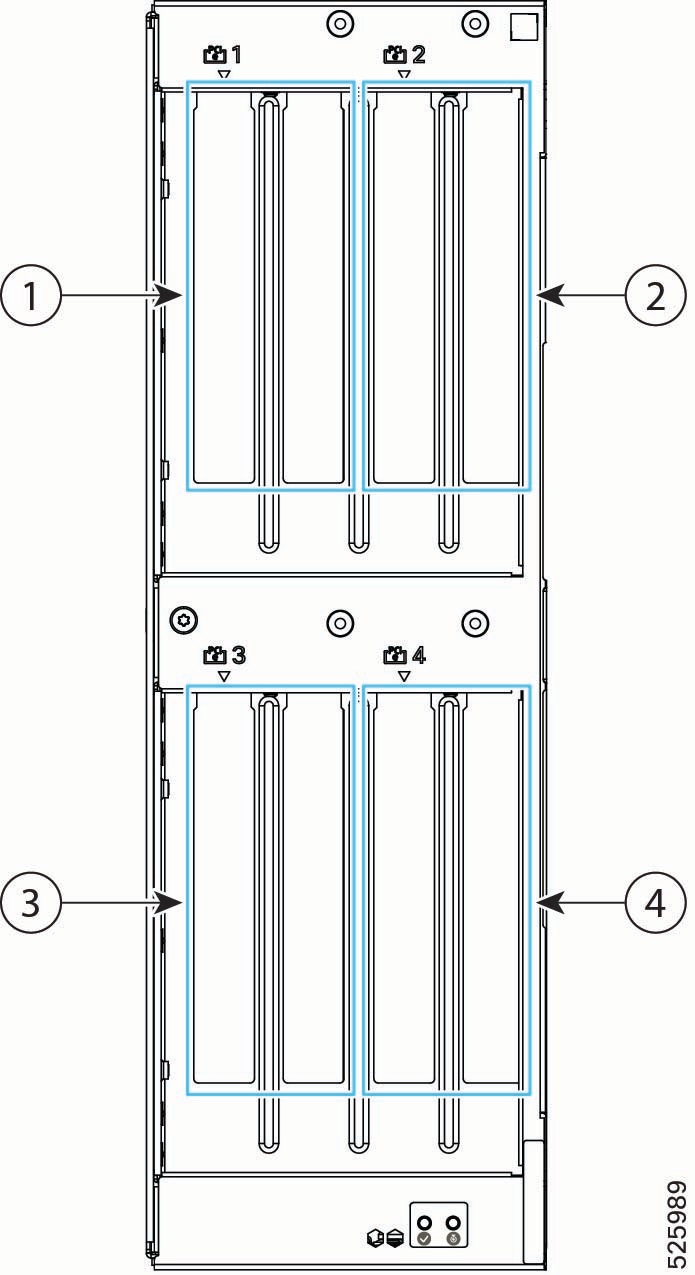
Note |
PCIe slot numbers are labeled onto the front of each X580p PCIe Node. |
|
1 |
Slot 1 for FHFL dual-slot GPU GPU cage A (which contains slots 1 and 2) is controlled by CPU1 on the Cisco UCS M8 compute node paired with the PCIe node |
2 |
Slot 2 for FHFL dual-slot GPU |
|
3 |
Slot 3 for FHFL dual-slot GPU.
GPU cage B (which contains slots 3 and 4) is controlled by CPU2 on the Cisco UCS M8 compute node paired with the PCIe node |
4 |
Slot 4 for FHFL dual-slot GPU. |
Supported GPUs
The following table shows the models and form factors of GPU supported by the Cisco UCS X580p PCIe Node. When the system is initially ordered, GPUs are installed at the factory, but additional GPUs can be ordered as spares as your deployment scales out. When additional GPUs are ordered, each GPU listed in the following table includes a power cable.
Any GPU cage can accept all of the supported GPUs. For example, Cage A is not "reserved" for only H200 GPUs.
However, be aware of the following GPU mixing consideration: GPUs can be mixed across the node, but not within GPU Cages. For example, H200 NVL GPUs can be installed in Cage A, and RTX PRO 6000 GPUs can be installed in Cage B. However, you cannot install a mix of H200 and RTX PRO 6000 GPUs in the same cage.
|
GPU |
Cisco PID |
|---|---|
|
NVIDIA L40S FHFL PCIe Gen 4 350W, x16 lanes (64 Gbps bidirectional), 48 GB memory |
UCSX-GPU-L40S= |
|
NVIDIA H200 NVL Dual Slot, FHFL PCIe Gen 5 600W, x16, 5x 8, or 4x 16 lanes, 141 GB HBM3e memory Two-Way NVLink Bridge for point-to-point GPU Interconnect support |
UCSX-GPU-H200-NVL= |
|
NVIDIA RTX PRO 6000 FHFL PCIe Gen 5 600W, x16 lanes, 141 GB memory |
UCSX-GPU-RTXP6000= |
Supported Network Adapters
Network adapters provide logical connections, such as signaling and data, for the PCIe nodes.
It is important to understand that supported network adapters are not physically installed on the Cisco UCS X580p PCIe Node, but they are required for GPU-to-GPU communication across the nodes. Instead, the network adapters are installed in the UCS X9516 X Fabric Modules (XFMs) that are present in the same Cisco UCS X9508 chassis that contains the PCIe nodes. For more information about the Cisco UCS X9516 XFM, which accepts the network adapters, see X Fabric Modules in the Cisco UCS X9508 Chassis Installation and Service Guide.
The following network adapters are required for end-to-end communication between the PCIe Nodes and the rest of the network.
|
Supported Adapter |
Cisco PID |
|---|---|
|
NVIDIA ConnectX-7 Network Adapter, PCIe Gen 5 HHHL, 1x400 Gbps QSFP port, 66W Maximum of two per Cisco UCS X9516 X Fabric Module (XFM) |
UCSX-P-N7S400GFO |
|
NVIDIA ConnectX-7 Network Adapter, PCIe Gen 5 HHHL, 2x200 Gbps QSFP port, 66W Maximum of two per Cisco UCS X9516 X Fabric Module (XFM) |
UCSX-P-N7D200GFO |
Required Hardware
The Cisco UCS X580p PCIe Node is part of an integrated system to provide GPU acceleration for Cisco UCS M8 compute nodes. For a complete system, the PCIe node requires the following hardware components.
-
An X-Series server chassis, such as the Cisco UCS X9508 Server Chassis, that contains the paired compute and PCIe Nodes and the Cisco X-Fabric Modules. For more information, go to the Cisco UCS X9508 Server Chassis Installation Guide.
-
Two Cisco UCS X9516 X-Fabric PCIe Gen 5 Switch Modules (UCSX-FS-9516) for the Cisco UCS X9508 Chassis to connect Cisco UCS M8 compute nodes to the Cisco UCS X580p PCIe Node in the X-Series Server chassis. For more information, go to the Cisco UCS X9508 Server Chassis Installation Guide.
-
Cisco UCS Compute Nodes that pair with the Cisco UCS X580p PCIe Node, such as the following:
-
Cisco UCS X210c M8 Compute Node with Intel® Xeon® 6 processors. For more information, go to the Cisco UCS X210c M8 Compute Node Installation and Service Guide.
-
Cisco UCS X215c M8 Compute Node with AMD® EPYC® processors. For more information, go to the Cisco UCS X215c M8 Compute Node Installation and Service Guide.
-
Cisco UCS X210c M7 Compute Node with Fifth Generation Intel® Xeon® Scalable Processors processors. For more information, go to the Cisco UCS X210c M7 Compute Node Installation and Service Guide.
Note
Although the Cisco UCS X210c M7 Compute Node offers an option with Fourth Generation Xeon® processors, this version is not supported with the Cisco UCS X580p PCIe Node.
-
-
Cisco UCS PCIe Gen 5 Mezz Card for X Fabric (UCSX-V5-PCIME), which is a rear mezzanine card required on each paired UCS M8 compute node.
-
The Cisco UCS X580p PCIe Node itself, up to two per Cisco UCS X9508 chassis, to pair with the M8 compute nodes.
-
GPU Cages, which are designed for full height, full length (FHFL) dual-slot GPUs. GPU cages are part of each PCIe Node. For more information, see GPU Cage Options.
-
GPUs, which provide the GPU processing offload and acceleration. For more information, see Supported GPUs.
 Feedback